Loading ...
Loading ...
Loading ...
Installation Instructions
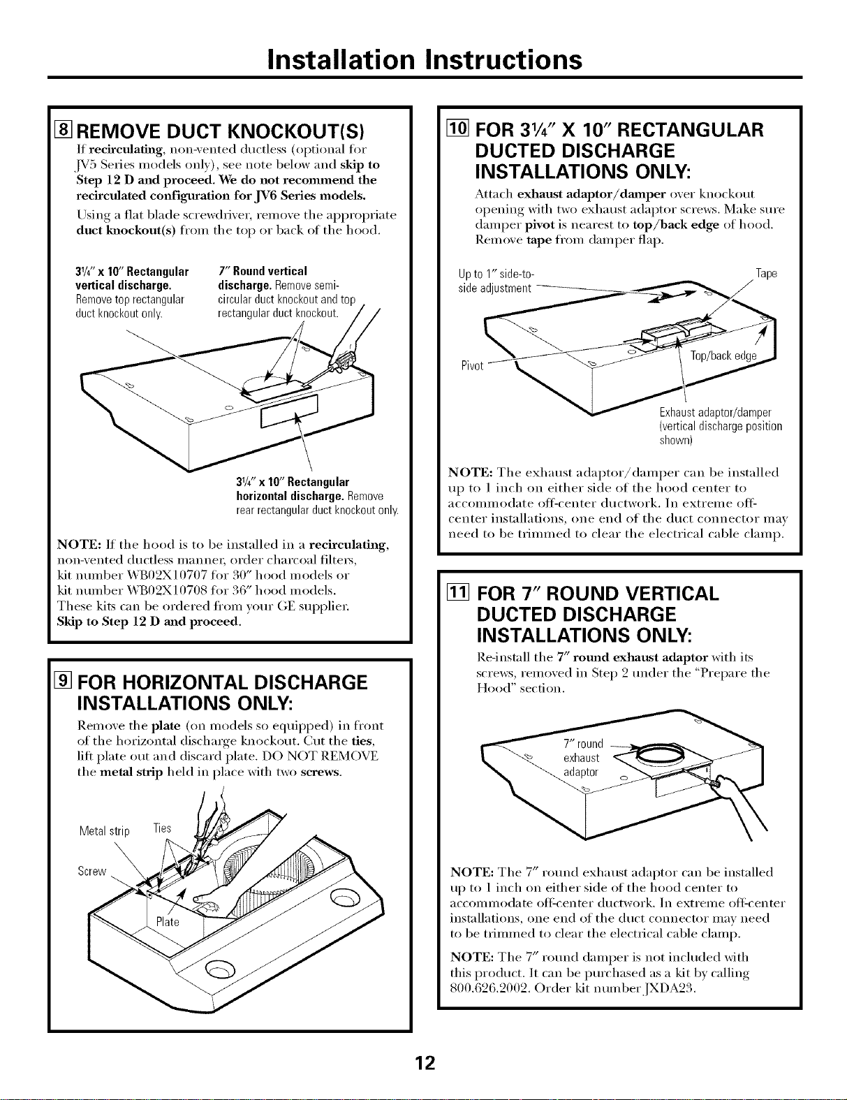
[] REMOVE DUCT KNOCKOUT(S)
If recirctdath_g, non-vented ductless (Ol_tional for
,IV5 Series models only), see uote below and skip to
Step 12 D and proceed. We do not recommend the
recirculated configuration for JV6 Series models.
Using a fiat blade screwdriver; remove the ai_i_ropriate
duct lmockout(s) fi'om the top or back of the hood.
3'/4"x I0" Rectangular
vertical discharge•
Removetop rectangular
ductknockoutonly.
7" Roundvertical
discharge, Removesemi-
circularduct knockoutandtop
rectangularductknockout.
3'/4"x 10" Rectangular
horizontal discharge• Remove
rear rectangular duct knockout only.
NOTE: If the hood is to be installed in a recirculating,
non-vented ductless manne_; order charcoal filters,
kit nmnber WB02X10707 fin" 30" hood models or
kit ntlillbeF WB02X10708 fin" 36" hood models.
These kits can be ordered ti'om yore" GE sui_plie_:
Skip to Step 12 D mid proceed.
[] FOR HORIZONTAL DISCHARGE
INSTALLATIONS ONLY:
Remove the plate (on models so equiI)ped ) in fl'ont
of the horizontal discharge knockout. Cut the ties,
lift plate out and discard plate. DO NOT REMOVE
the metaJ strip held in place with two screws.
Metalstrip Ties
Screw
[]
FOR 31/4" X 10" RECTANGULAR
DUCTED DISCHARGE
INSTALLATIONS ONLY:
Mtach exhaust adaptor/da_aper over knockout
opening with two exhaust adaptor screws. Make sure
damper pivot is nearest to top/back edge of hood.
Remove tape ti'om damper flap.
Upto 1" side-to- Tape
sideadjustment
Pivot
Exhaustadaptor/damper
(verticaldischargeposition
shown)
NOTE: The exhaust adai)tor/damper can be installed
up to 1 inch on either side of the hood center to
aCCOlillilo(late off=center ductwork. ]n extreme off =
center installations, one end of the duct connector may
need to be trimmed to clear the electrical cable clamp.
[] FOR 7" ROUND VERTICAL
DUCTED DISCHARGE
INSTALLATIONS ONLY:
Re-install the 7" round exhaust adaptor with its
screws, removed in Step 2 trader the "Prepare the
Hood" section.
NOTE: The 7" rotmd exhaust adaptor can be installed
up to 1 inch on either side of the hood center to
aCCOllllllodate oItcenter dtlctwork. In exti'ellle oItLcenter
instnllations, one end of the duct connector may need
to be trimmed to clear the electrical cable clamp.
NOTE: The 7" r(mnd damper is not included with
this i_roduct. It can be i_m'chased as a kit b) calling
800.626.2002. Order kit nmnber,]'X[ A2..
12
Loading ...
Loading ...
Loading ...