
SafetyInstructions& Operator'sManual for
LAWNTRACTOR
SERIES0
f
Models
LT195420(7800206)
CLT195420 (7800313)
LT23460(7800207)
CLT23460(7800315)
LT24520 (7800212)
CLT24520(7800317)
SLT23460 (7800342)
SLT24520 (7800343)
CSLT23460(7800344)
CSLT24520(7800345)
SLT23460FC (7800316)
SLT24520FC (7800318)
J
NOTE:Specifications are correctat time of printing and are subjectto changewithout notice.
* Actual sustainedengine power will likely be lower dueto operating limitations and environmentalfactors. Please refer to 'EnginePower Rating Information' for
further details.
SNAPPERMcoooooo.o_.,_o_o_,
Manual No.7102556 (Rev. '-', 4/17/2008)
TP lO0-5396---TC-N

Thankyoufor purchasing this quality-built Snapper product. We are pleasedthat you've placedyour confidencein the Snapper
brand. When operatedand maintained according to the instructions in this manual,your Snapper mower will provide many
years of dependableservice.
Thismanualcontainssafety information to makeyou awareof the hazardsand risks associatedwith mowers and howto
avoid them. BecauseSnapper does not necessarily know all the applications this mower could be usedfor, it is important that
you readand understand these instructions. Keepthis manualnear the mower for convenient reference.
Thismowerrequiresfinal assemblybeforeuse. Referto the Assembly section of this manualfor instructions on final
assembly procedures. Follow the instructions completely.
Where to Find Us
You never haveto lookfar to find Briggs & Stratton support and servicefor your mower. Consultyour Yellow Pages.There are
over 30,000 Briggs & Stratton authorized service dealersworldwide who provide quality service. You canalso contact Snapper
Customer Service at 1-800-317-7833, or on the Internet at www.snapper.com.
Mower
Model Number
Serial Number
Engine
Model
Type
Trim
DatePurchased
IIIIIIIII
It is very important that you registeryour purchasewith Snapperto ensurewarranty coverage.Pleasemailyour product
registration cardto:
Snapper at P.O.Box 1379, McDonough, Georgia 30253.
SNAPPERis a trademarkof
Briggs& StrattonPower ProductsGroup,LLC
Jefferson,WI, USA.
Briggs& StrattonYard Power ProductsGroup
Copyright© 2008, Briggs& StrattonCorporation
Milwaukee, WI, USA. All RightsReserved.
TableofContents
D_
€1D
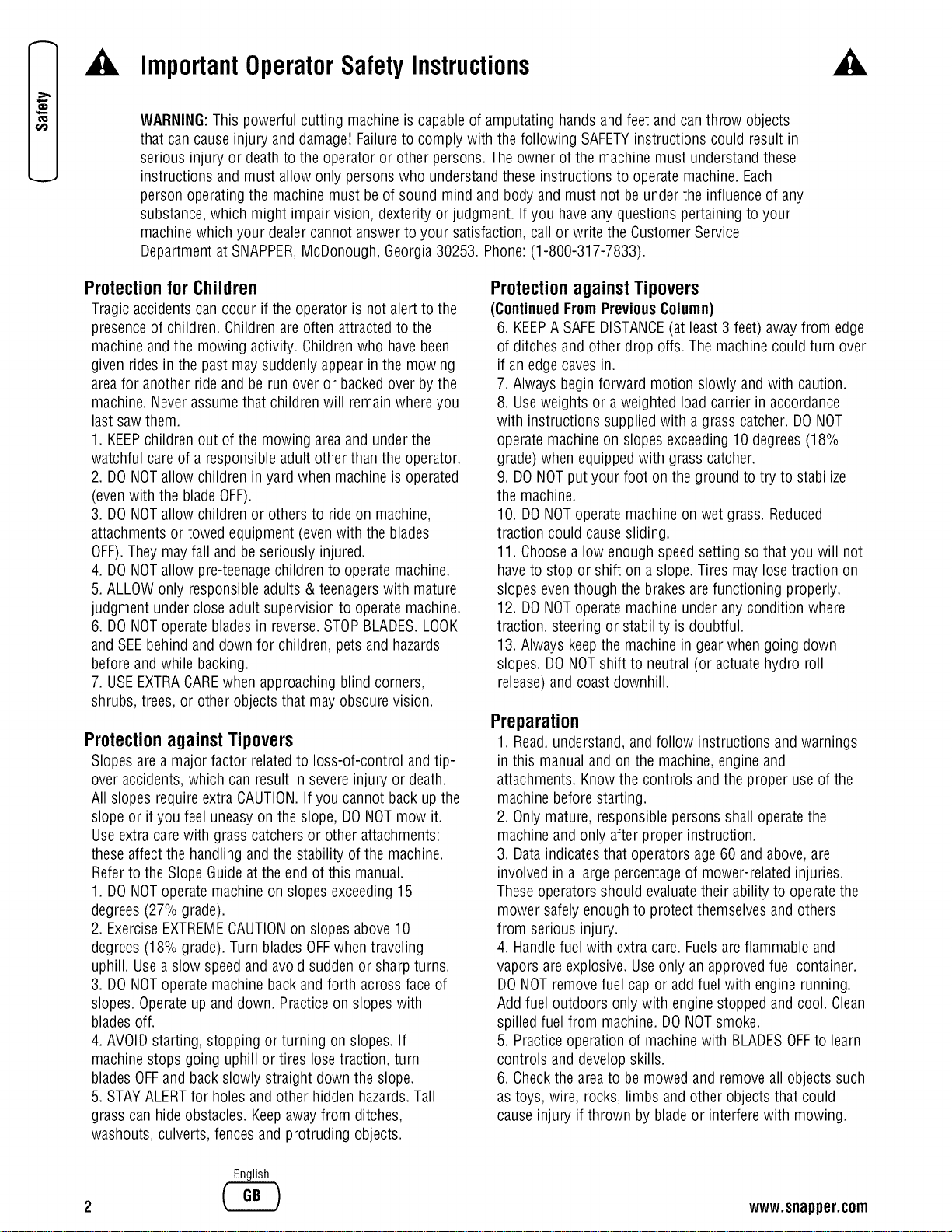
Operator Safety .................................. 2
Important OperatorSafety Instructions ............................. 2
International Pictorials.......................................... 5
Assembly ...................................... 6
Parts Bag- Contents ........................................... 6
Installing the Seat ............................................. 7
Assembling the SteeringWheel................................... 7
MaintenanceFreeBattery........................................ 8
IMPORTANT!BeforeYou Start Mowing ............................ 9
FeaturesandControls.............................. 11
Operation ...................................... 12
Attachments.................................................. 12
Using Controls................................................ 12
Driving and Stopping the Unit .................................... 13
Mowing ..................................................... 16
Engine Operation.............................................. 18
Tips ........................................................ 19
Maintenance.................................... 20
MaintenanceSchedule.......................................... 20
GeneralRecommendations ...................................... 21
Inspection ................................................... 21
Adjustments.................................................. 22
MaintenanceFreeBattery........................................ 26
Lubrication................................................... 27
Mower DeckMaintenance....................................... 28
Misc........................................................ 38
Storage ..................................................... 39
Troubleshooting.................................. 40
Specifications ................................... 42
SlopeGuide .................................... 43
Warranties ..................................... 45
GeneralWarranty.............................................. 45
WARNING
Batteryposts, terminals and relatedaccessoriescontain
lead and lead compounds, chemicals known to the Stateof
Californiato cause cancer and birth defects or other
reproductiveharm. Wash handsafter handling.
WARNING
Engineexhaust, some of its constituents, and certain
vehicle components contain or emit chemicals known to
the State of California to causecancer or other reproductive
harm.
English
¢'D
3
o"
0
0
'ID
0
.,q
0
CD
0
0
--t
CD
0
r.fJ
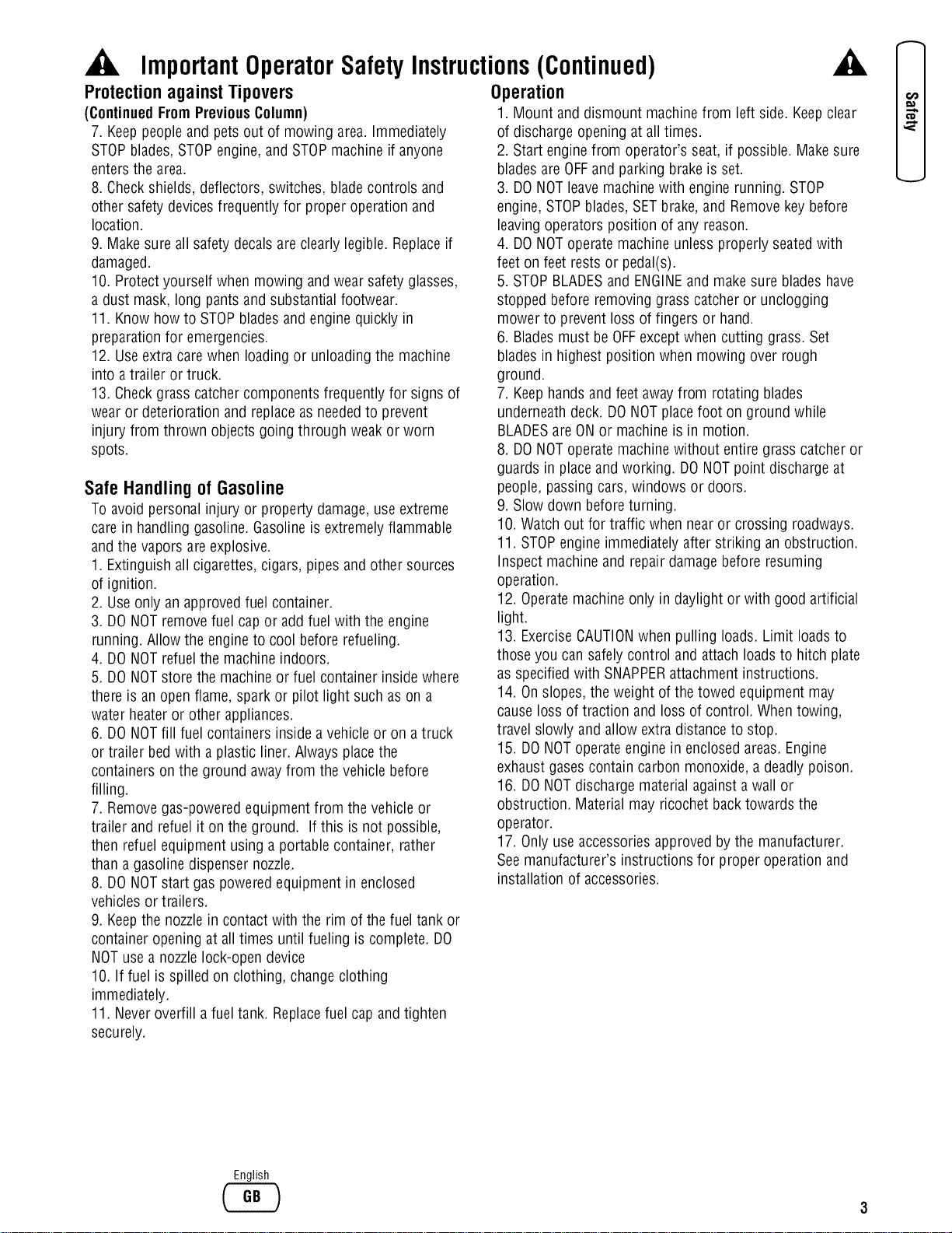
ImportantOperatorSafetyInstructions
,&
WARNING:This powerful cutting machine is capableof amputating hands and feet and can throw objects
that cancause injury and damage! Failureto comply with the following SAFETYinstructions could result in
serious injury or deathto the operator or other persons. Theowner of the machine must understandthese
instructions and must allow only persons who understandtheseinstructions to operatemachine. Each
person operating the machine must be of sound mind and body and must not be underthe influenceof any
substance,which might impair vision, dexterity or judgment. If you haveany questions pertainingto your
machine which your dealercannot answerto your satisfaction, call or write the Customer Service
Department at SNAPPER,McDonough,Georgia30253. Phone:(1-800-317-7833).
Protection for Children
Tragic accidents canoccur if the operator is not alertto the
presenceof children. Children are often attracted to the
machine andthe mowing activity. Childrenwho havebeen
given rides in the past may suddenly appear in the mowing
areafor another ride and be run over or backedover by the
machine.Never assumethat children will remain whereyou
last saw them.
1. KEEPchildren out of the mowing area and under the
watchful careof a responsible adult other than the operator.
2. DONOTallow children in yard when machine is operated
(evenwith the bladeOFF).
3. DONOTallow children or others to ride on machine,
attachmentsor towed equipment (evenwith the blades
OFF).Theymay fall and be seriously injured.
4. DONOTallow pre-teenagechildren to operate machine.
5.ALLOW only responsible adults & teenagerswith mature
judgment under close adult supervision to operate machine.
6. DONOToperatebladesin reverse.STOPBLADES.LOOK
and SEEbehind and down for children, pets and hazards
beforeand while backing.
7. USEEXTRACAREwhen approaching blind corners,
shrubs, trees, or other objects that may obscure vision.
Protection against Tipovers
Slopesare a major factor relatedto loss-of-control and tip-
overaccidents, which can result in severe injury or death.
All slopes require extra CAUTION.If you cannot back up the
slopeor if you feel uneasyon the slope, DONOTmow it.
Useextra care with grass catchers or other attachments;
these affect the handling and the stability of the machine.
Referto the Slope Guideat the end of this manual.
1. DONOToperatemachine on slopes exceeding15
degrees(27% grade).
2. ExerciseEXTREMECAUTIONon slopes above10
degrees(18% grade).Turn bladesOFFwhen traveling
uphill. Usea slow speedand avoidsudden or sharp turns.
3. DONOToperatemachine back and forth acrossface of
slopes.Operateup and down. Practiceon slopes with
bladesoff.
4. AVOID starting, stopping or turning on slopes. If
machine stops going uphill or tires losetraction, turn
bladesOFFand back slowly straight down the slope.
5. STAYALERTfor holesand other hidden hazards.Tall
grass can hide obstacles. Keepawayfrom ditches,
washouts, culverts, fencesand protruding objects.
Protection against Tipovers
(ContinuedFromPreviousColumn)
6. KEEPA SAFEDISTANCE(at least 3 feet) away from edge
of ditches and other drop offs. Themachine could turn over
if an edge cavesin.
7. Alwaysbegin forward motion slowly and with caution.
8. Useweights or a weighted load carrier in accordance
with instructions supplied with a grass catcher. DONOT
operate machine on slopes exceeding10 degrees(18%
grade) when equippedwith grass catcher.
9. DONOTput your foot on the ground to try to stabilize
the machine.
10. DONOToperatemachine on wet grass. Reduced
traction could causesliding.
11. Choosea low enough speedsetting so that you will not
haveto stop or shift on a slope. Tires may lose traction on
slopes eventhough the brakes are functioning properly.
12. DONOToperatemachine under any condition where
traction, steering or stability is doubtful.
13. Always keepthe machine in gear when going down
slopes. DONOTshift to neutral (or actuatehydro roll
release)and coastdownhill.
Preparation
1. Read,understand, and follow instructions and warnings
in this manualand on the machine, engine and
attachments. Know the controls and the proper use of the
machine beforestarting.
2. Onlymature, responsible persons shall operatethe
machineand only after proper instruction.
3. Dataindicates that operators age 60 and above,are
involved in a large percentageof mower-related injuries.
These operators should evaluatetheir ability to operatethe
mower safely enough to protect themselvesand others
from serious injury.
4. Handlefuel with extra care. Fuelsareflammable and
vapors are explosive. Useonly an approvedfuel container.
DONOTremovefuel capor addfuel with engine running.
Add fuel outdoors only with engine stopped and cool. Clean
spilled fuel from machine. DONOTsmoke.
5. Practiceoperation of machinewith BLADESOFFto learn
controls and developskills.
6. Checkthe areato be mowed and removeall objects such
as toys, wire, rocks, limbs and other objects that could
cause injury if thrown by bladeor interfere with mowing.
English
www.snapper.com
,A
ImportantOperatorSafetyInstructions(Continued)
Protection againstTipovers
(ContinuedFromPreviousColumn)
7. Keeppeople and pets out of mowing area.Immediately
STOPblades,STOPengine, and STOPmachine if anyone
entersthe area.
8. Checkshields, deflectors, switches, blade controls and
other safety devicesfrequently for proper operation and
location.
9. Make sure all safety decals are clearly legible. Replaceif
damaged.
10. Protectyourself when mowing andwear safety glasses,
a dust mask, long pants and substantial footwear.
11. Know how to STOPbladesand engine quickly in
preparationfor emergencies.
12. Useextra carewhen loading or unloading the machine
into a trailer or truck.
13. Checkgrass catchercomponents frequently for signs of
wear or deterioration and replaceas neededto prevent
injury from thrown objects going through weak or worn
spots.
Safe Handling of Gasoline
To avoid personal injury or property damage,use extreme
carein handling gasoline.Gasolineis extremelyflammable
andthe vapors are explosive.
1. Extinguish all cigarettes, cigars, pipes and other sources
of ignition.
2. Useonly an approvedfuel container.
3. DONOTremove fuel cap or add fuel with the engine
running. Allow the engineto cool before refueling.
4. DONOTrefuelthe machine indoors.
5. DONOTstore the machineor fuel container inside where
there is an open flame, spark or pilot light such as on a
water heateror other appliances.
6. DONOTfill fuel containers inside a vehicle or on atruck
or trailer bed with aplastic liner. Always placethe
containerson the ground away from the vehicle before
filling.
7. Removegas-poweredequipment from the vehicle or
trailer and refuelit on the ground. If this is not possible,
then refuelequipment using a portablecontainer, rather
than a gasolinedispenser nozzle.
8. DONOTstart gas poweredequipment in enclosed
vehicles or trailers.
9. Keepthe nozzlein contact with the rim of the fuel tank or
container opening at all times until fueling is complete. DO
NOTusea nozzle lock-open device
10. If fuel is spilled on clothing, change clothing
immediately.
11. Neveroverfill a fueltank. Replacefuel cap andtighten
securely.
Operation
1. Mount and dismount machine from left side. Keepclear
of discharge opening at all times.
2. Start engine from operator's seat, if possible. Makesure
bladesare OFFand parking brakeis set.
3. DONOTleavemachinewith engine running. STOP
engine, STOPblades, SETbrake, and Removekey before
leavingoperators position of any reason.
4. DONOToperatemachine unless properly seatedwith
feet on feet rests or pedal(s).
5. STOPBLADESand ENGINEand makesure bladeshave
stopped before removing grass catcher or unclogging
mower to prevent loss of fingers or hand.
6. Bladesmust be OFFexceptwhen cutting grass. Set
bladesin highest position when mowing over rough
ground.
7. Keephandsand feet awayfrom rotating blades
underneathdeck. DONOTplacefoot on ground while
BLADESareONor machine is in motion.
8. DONOToperatemachine without entire grass catcher or
guards in placeand working. DONOTpoint discharge at
people,passing cars, windows or doors.
9. Slow down beforeturning.
10. Watchout for traffic when near or crossing roadways.
11. STOPengine immediately after striking an obstruction.
Inspect machine and repair damagebefore resuming
operation.
12. Operatemachine only in daylight or with good artificial
light.
13. ExerciseCAUTIONwhen pulling loads. Limit loadsto
those you can safelycontrol and attach loadsto hitch plate
as specified with SNAPPERattachment instructions.
14. Onslopes, the weight of the towed equipment may
cause loss of traction and loss of control. When towing,
travel slowly and allow extra distanceto stop.
15. DONOToperateengine in enclosedareas. Engine
exhaust gasescontain carbon monoxide, a deadly poison.
16. DONOTdischarge material against a wall or
obstruction. Material may ricochet back towards the
operator.
17. Onlyuse accessoriesapprovedby the manufacturer.
See manufacturer's instructions for proper operation and
installation of accessories.
English
ImportantOperatorSafetyInstructions(Continued)
Towing
1.Tow only with a machine that hasa hitch designedfor
towing. DONOTattachtowed equipment exceptat the hitch
point.
2. Follow the manufacturer's recommendationfor weight
limits for towed equipment and towing on slopes.
3. DONOTallow children or others on towed equipment.
4. On slopes,the weight of the towed equipment may cause
loss of traction and loss of control.
5.Travel slowly and allow extra distanceto stop.
Maintenance
1. DONOTstore machineor fuel container inside where
fumes may reachan open flame, spark or pilot light such as
in a water heater,furnace, clothes dryer or other gas
appliance.Allow engine to cool before storing machine in
an enclosure.Store fuel container out of the reachof
children in a well ventilated, unoccupied building.
2. Keepengine free of grass, leavesor excess greaseto
reducefire hazardand engineoverheating.
3.When draining fuel tank, drain fuel into an approved
container outdoors and away from open flame.
4. Checkbrakesfrequently; adjust, repair or replaceas
needed.
5. Keepall bolts, nuts and screws properly tight. Checkthat
all cotter pins are in proper position.
A
Maintenance
(ContinuedFromPreviousColumn)
6. Alwaysprovide adequateventilation when running
engine. Exhaustgasescontain carbon monoxide, an
odorless and deadly poison.
7. Disconnect negative(black) cablefrom battery before
performing maintenanceor service. Cranking enginecould
cause injury.
8. DONOTwork under machinewithout safety blocks.
9. Serviceengine and makeadjustments only when engine
is stopped. Removespark plug wire(s) from spark plug(s)
and securewire(s) away from spark plug(s).
10. DONOTchangeengine governor speedsettings or
overspeed engine.
11. Lubricate machine at intervals specified in manualto
prevent controls from binding.
12. Mower bladesare sharp and can cut. Wrap the blades
or wear heavy leathergloves and useCAUTIONwhen
handling them.
13. DONOTtest for spark by grounding spark plug next to
spark plug hole; spark plug could ignite gas exitingengine.
14. Havemachine serviced by an authorized SNAPPER
dealer at least once ayear and havethe dealerinstall any
newsafety devices.
15. Maintain or replacesafetyand instruction labelsas
necessary.
16. Use only genuine SNAPPERreplacementparts to
assure that original standards are maintained.
English
www.snapper.com
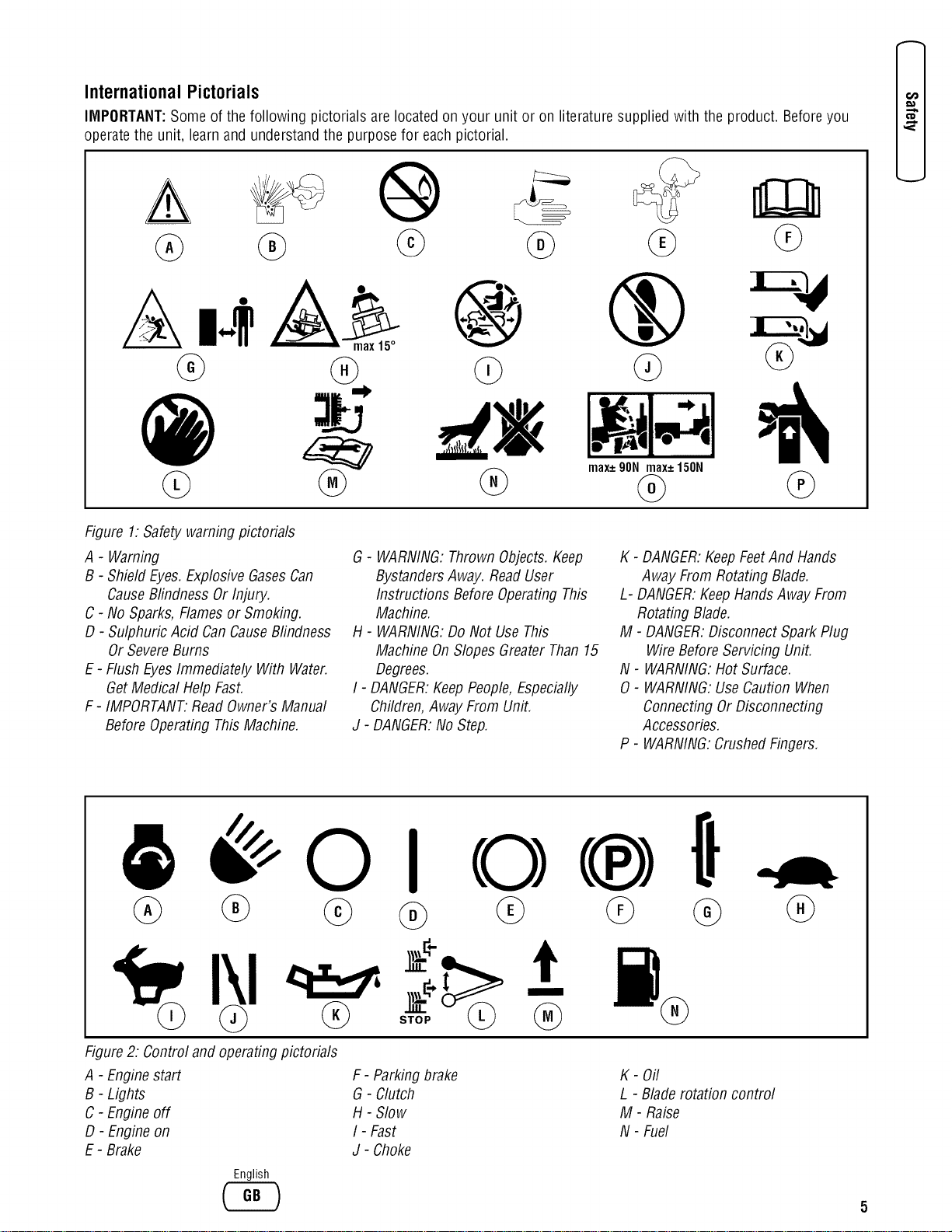
International Pictorials
IMPORTANT:Some of the following pictorials are located on your unit or on literature supplied with the product. Beforeyou
operatethe unit, learn and understand the purpose for eachpictorial.
@
14,_ max15°
@ @
max+90Nmax+150N
Figure 1:Safety warningpictorials
A - Warning
B - Shield Eyes.Explosive GasesCan
CauseBlindness Or Injury.
C - No Sparks,Flamesor Smoking.
D - Sulphuric Acid CanCauseBlindness
OrSevereBums
E - Flush EyesImmediately With Water.
GetMedical HelpFast.
F- IMPORTANT.ReadOwner'sManual
BeforeOperating ThisMachine.
G- WARNING:Thrown Objects.Keep
BystandersAway. ReadUser
Instructions Before OperatingThis
Machine.
H - WARNING:DoNot Use This
Machine OnSlopes GreaterThan15
Degrees.
I - DANGER:KeepPeople,Especially
Children,Away From Unit.
J - DANGER:No Step.
K - DANGER:KeepFeetAnd Hands
Away From Rotating Blade.
L- DANGER:KeepHandsAway From
Rotating Blade.
M - DANGER:Disconnect SparkPlug
WireBeforeServicing Unit.
N - WARNING:Hot Surface.
0 - WARNING:UseCaution When
Connecting Or Disconnecting
Accessories.
P - WARNING:CrushedFingers.
D3
€1D
8 0 I
@ @
Figure2: Control and operatingpictorials
A - Enginestart
B- Lights
C - Engineoff
D - Engine on
E- Brake
F- Parkingbrake
G- Clutch
H - Slow
I - Fast
J - Choke
K- Oil
L - Blade rotation control
M- Raise
N - Fuel
English
@
E
€_
Assembly
Readand follow theassemblyand adjustment
instructionsfor yourmower.
Allfastenersare inthe parts bag. Do notdiscard
anypartsor material untilthe unit
isassembled.
NOTE:In this instruction book, left and right describe the
location of a part with the operator on the seat.
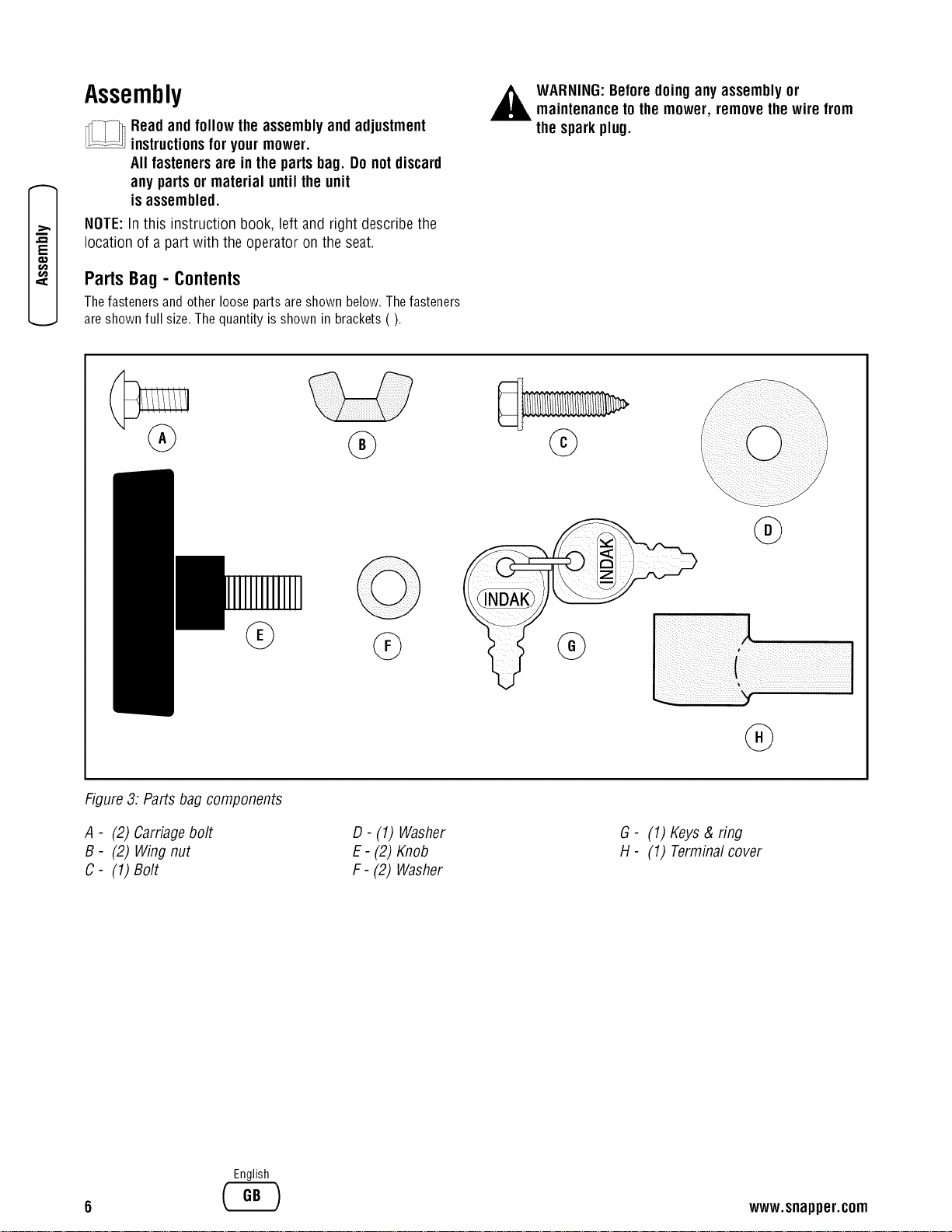
Parts Bag - Contents
Thefasteners and other loose parts areshown below. Thefasteners
areshown full size. The quantity is shown in brackets ().
,_ WARNING:Beforedoinganyassemblyor
maintenanceto themower, removethe wire from
the sparkplug.
@
G
Figure3: Parts bag components
A - (2) Carriagebolt
B - (2) Wingnut
C- (1) Bolt
D- (1) Washer
E- (2) Knob
F- (2) Washer
G- (1) Keys& ring
H- (1) Terminal cover
English
www.snapper.com
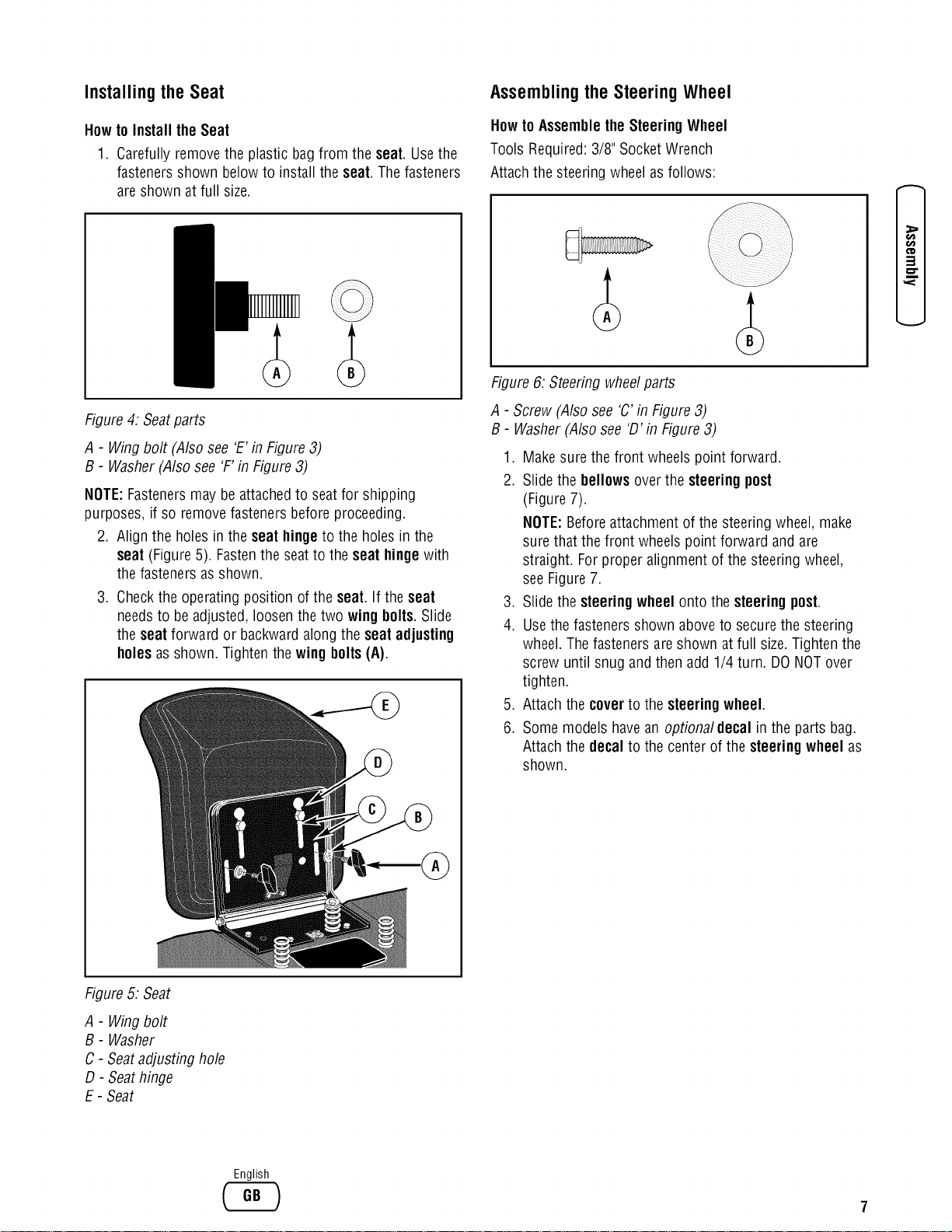
Installing the Seat
Howto Install the Seat
1. Carefully removethe plastic bagfrom the seat. Usethe
fasteners shown belowto install the seat. Thefasteners
are shown at full size.
Assemblingthe SteeringWheel
Howto AssembletheSteeringWheel
Tools Required:3/8" SocketWrench
Attachthe steering wheel asfollows:
t_
t_
3
o"
Figure4: Seatparts
A - Wingbolt (Also see 'E'in Figure3)
B - Washer(Also see 'F'in Figure 3)
NOTE:Fastenersmay be attachedto seat for shipping
purposes, if so remove fasteners before proceeding.
2. Align the holes inthe seat hinge to the holes in the
seat (Figure 5). Fastenthe seat to the seat hingewith
the fasteners asshown.
3. Checkthe operating position of the seat. If the seat
needsto be adjusted,loosen the two wing bolls.Slide
the seat forward or backwardalong the seat adjusting
holesas shown. Tighten the wingbolts(A).
Figure 6: Steering wheelparts
A - Screw (Also see 'C' in Figure3)
B- Washer (Also see 'D' in Figure3)
1. Make sure the front wheels point forward.
2. Slide the bellows overthe steering post
(Figure7).
NOTE:Beforeattachment of the steering wheel, make
surethat the front wheels point forward and are
straight. Forproper alignment of the steering wheel,
seeFigure7.
3. Slide the steeringwheel onto the steeringpost.
4. Usethe fasteners shown aboveto secure the steering
wheel. Thefasteners are shown at full size.Tighten the
screw until snug and then add 1/4 turn. DONOTover
tighten.
5. Attach the coverto the steeringwheel.
6. Some models havean optional decal in the parts bag.
Attach the decal to the center of the steeringwheel as
shown.
Figure5: Seat
A - Wingbolt
B - Washer
C - Seatadjusting hole
D- Seathinge
E - Seat
English
E
G
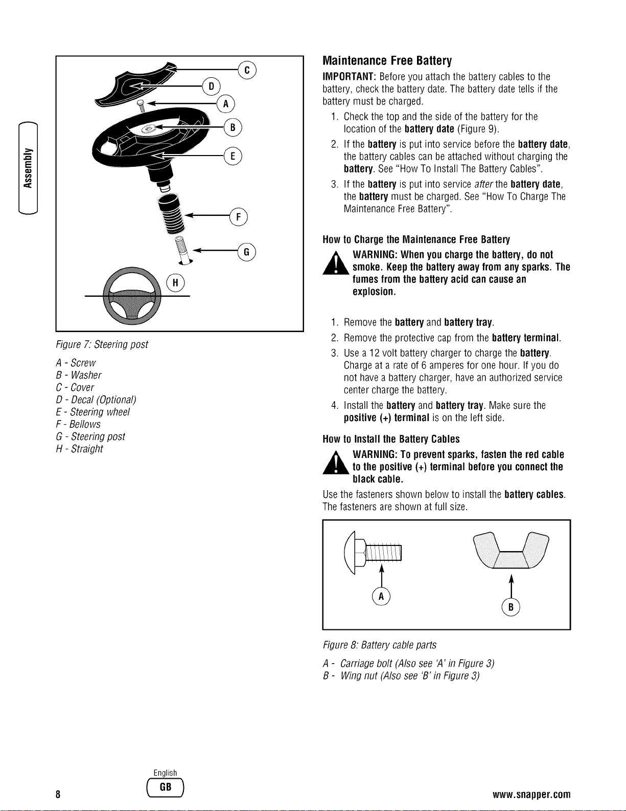
Figure 7. Steeringpost
A - Screw
B - Washer
C - Cover
D- Decal (Optional)
E- Steering wheel
F- Bellows
G - Steeringpost
H- Straight
MaintenanceFreeBattery
IMPORTANT:Beforeyou attachthe batterycables to the
battery, checkthe battery date.The battery datetells if the
battery must be charged.
1. Checkthe top and the side of the batteryfor the
location of the battery date (Figure9).
2. If the batteryis put into service beforethe batterydate,
the battery cables can be attachedwithout charging the
battery.See"How To Install The BatteryCables".
3. If the batteryis put into serviceafterthe batterydate,
the batterymust be charged. See"How To ChargeThe
MaintenanceFreeBattery".
Howto ChargetheMaintenanceFree Battery
,_ WARNING:Whenyou chargethe battery,do not
smoke. Keepthebatteryaway from anysparks.The
fumesfrom the batteryacid cancausean
explosion.
1. Removethe batteryand batterytray.
2. Removethe protective cap from the batteryterminal.
3. Use a 12 volt battery chargerto chargethe battery.
Chargeat a rate of 6 amperesfor one hour. If you do
not havea battery charger, havean authorized service
center chargethe battery.
4. Install the batteryandbatterytray. Make surethe
positive (+) terminal is on the left side.
Howto Install the BatteryCables
WARNING:To preventsparks,fastenthered cable
to the positive(+) terminal beforeyou connectthe
blackcable.
Usethe fasteners shown belowto install the batterycables.
Thefasteners are shown at full size.
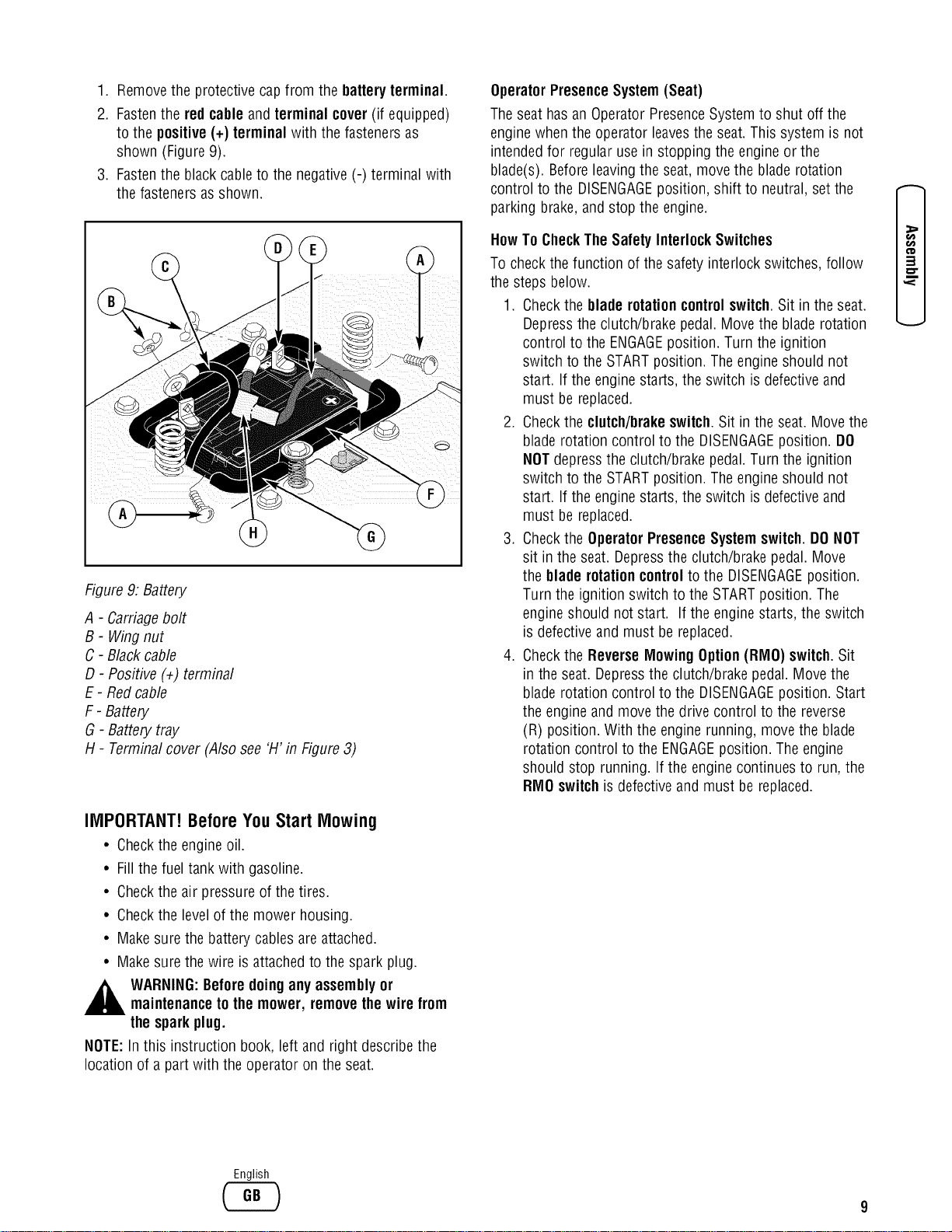
Figure8: Batterycableparts
A - Carriagebolt (Also see 'A' in Figure3)
B- Wing nut (Also see 'B'in Figure 3)
English
www.snapper.com
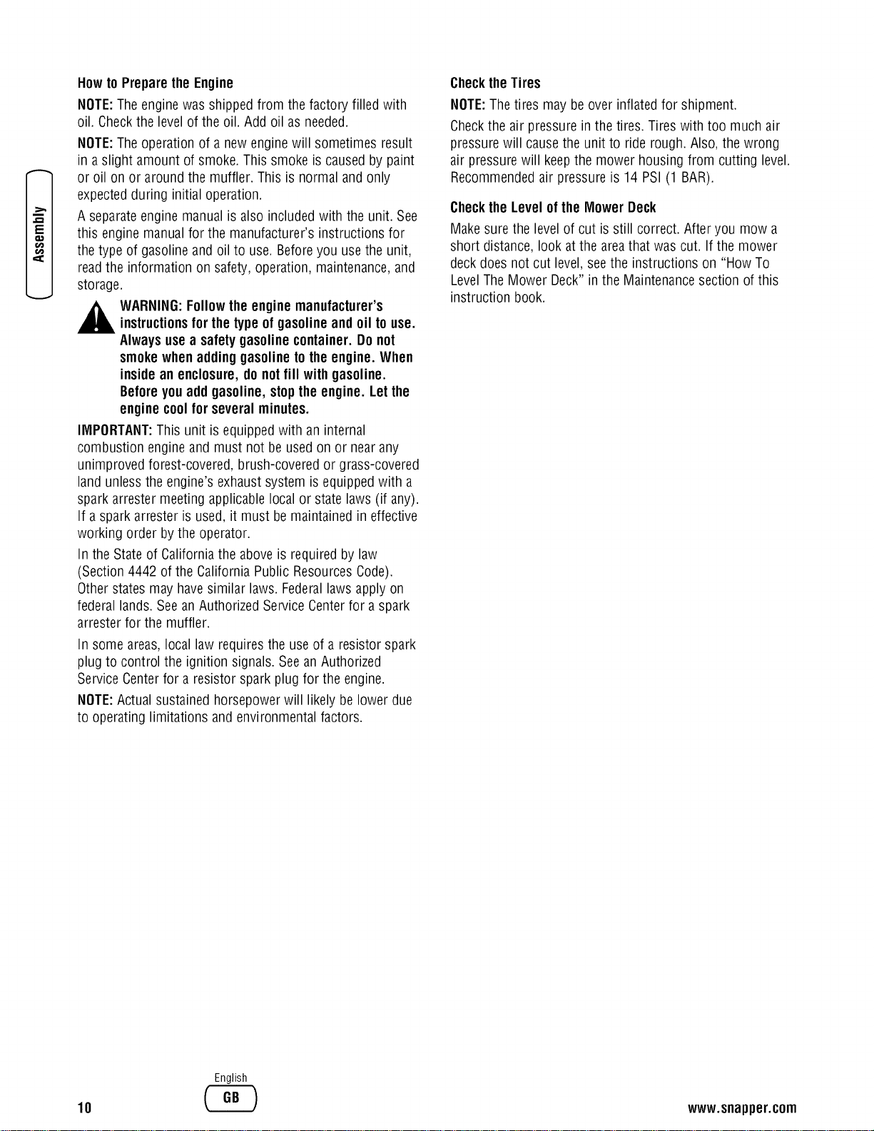
1. Removethe protective capfrom the batteryterminal.
2. Fastenthe red cable and terminal cover(if equipped)
to the positive(+) terminal with the fasteners as
shown (Figure9).
3. Fastenthe blackcableto the negative(-) terminal with
the fasteners asshown.
Figure 9: Battery
A - Carriagebolt
B - Wingnut
C - Blackcable
D - Positive (÷) terminal
E - Redcable
F- Battery
G - Battery tray
H - Terminalcover (Also see 'H' in Figure 3)
IMPORTANT!BeforeYouStart Mowing
• Checkthe engineoil.
• Fill the fuel tank with gasoline.
• Checkthe air pressure of the tires.
• Checkthe levelof the mower housing.
• Make sure the battery cables areattached,
• Make surethe wire is attachedto the spark plug.
,_ WARNING:Beforedoing anyassemblyor
maintenanceto themower, removethe wire from
thesparkplug.
NOTE:In this instruction book, left and right describe the
location of a part with the operator on the seat.
OperatorPresenceSystem(Seat)
Theseat has an Operator PresenceSystemto shut off the
engine whenthe operator leavesthe seat.This system is not
intendedfor regular use in stopping the engine or the
blade(s). Beforeleavingthe seat, movethe blade rotation
control to the DISENGAGEposition, shift to neutral, set the
parking brake,and stop the engine.
HowTo CheckThe Safety InterlockSwitches
To checkthe function of the safety interlock switches, follow
the steps below.
1. Checkthe bladerotation controlswitch. Sit in the seat.
Depressthe clutch/brake pedal.Move the blade rotation
control to the ENGAGEposition. Turn the ignition
switch to the STARTposition. The engine should not
start. If the engine starts, the switch is defective and
must be replaced.
2. Checkthe clutch/brakeswitch.Sit in the seat. Movethe
blade rotation control to the DISENGAGEposition. DO
NOTdepressthe clutch/brake pedal.Turn the ignition
switch to the STARTposition. The engine should not
start. If the engine starts, the switch is defective and
must be replaced.
3. Checkthe OperatorPresence System switch.DONOT
sit in the seat. Depressthe clutch!brake pedal.Move
the blade rotation controlto the DISENGAGEposition.
Turn the ignition switch to the STARTposition. The
engine should not start. If the engine starts, the switch
is defective and must be replaced.
4. Checkthe ReverseMlowingOption(RIVlO)switch.Sit
in the seat. Depressthe clutch/brake pedal. Move the
blade rotation control to the DISENGAGEposition. Start
the engine and move the drive control to the reverse
(R) position. With the engine running, move the blade
rotation control to the ENGAGEposition. The engine
should stop running. If the engine continues to run, the
RIVlOswitch is defective and must be replaced.
O0
3
o"
English
E
€_
Howto Preparethe Engine
NOTE:Theenginewas shipped from the factory filled with
oil. Checkthe level of the oil. Add oil as needed.
NOTE:Theoperation of a newengine will sometimes result
in a slight amount of smoke. This smoke is causedby paint
or oil on or around the muffler. This is normal and only
expectedduring initial operation.
A separateengine manual is also included with the unit. See
this engine manual for the manufacturer's instructions for
the type of gasolineand oil to use. Beforeyou usethe unit,
read the information on safety, operation, maintenance,and
storage.
,_ WARNING:Followthe enginemanufacturer's
instructionsfor thetype ofgasolineand oil touse.
Alwaysusea safety gasolinecontainer. Do not
smokewhenaddinggasolinetothe engine.When
insidean enclosure,do notfill with gasoline.
Beforeyouadd gasoline, stopthe engine. Letthe
enginecoolfor several minutes.
IMPORTANT:This unit is equippedwith an internal
combustion engine and must not be used on or nearany
unimproved forest-covered, brush-coveredor grass-covered
land unlessthe engine'sexhaust system is equippedwith a
spark arrester meeting applicablelocal or state laws (if any).
If a spark arrester is used, it must be maintained in effective
working order bythe operator.
In the State of Californiathe aboveis required by law
(Section 4442 of the California Public ResourcesCode).
Otherstates may havesimilar laws. Federallaws apply on
federal lands. Seean Authorized Service Centerfor a spark
arrester for the muffler.
In some areas,local law requiresthe useof a resistor spark
plug to control the ignition signals. Seean Authorized
Service Centerfor a resistor spark plug for the engine.
NOTE:Actual sustained horsepowerwill likely be lower due
to operating limitations and environmentalfactors.
ChecktheTires
NOTE:The tires may be over inflated for shipment.
Checkthe air pressure in the tires. Tires with too much air
pressure will cause the unit to riderough. Also, the wrong
air pressure will keepthe mower housing from cutting level.
Recommendedair pressure is 14 PSI(1 BAR).
Checkthe Level ofthe MowerDeck
Make sure the levelof cut is still correct. After you mow a
short distance, look atthe areathat was cut. If the mower
deck does not cut level, seethe instructions on "HowTo
LevelThe Mower Deck" inthe Maintenancesection of this
instruction book.
10
English
www.snapper.com
FeaturesandControls
\
/
0
0
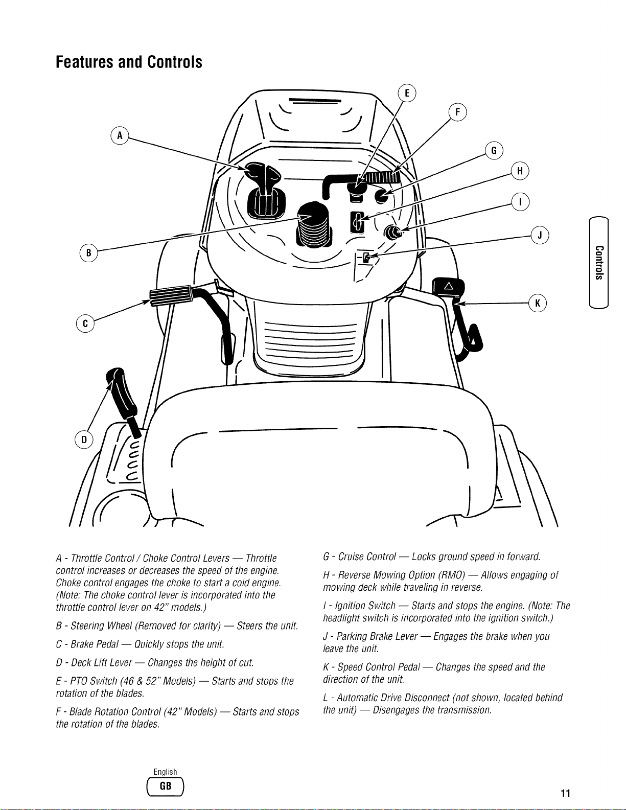
A - ThrottleControl/Choke Control Levers -- Throttle
control increasesor decreasesthe speedof the engine.
Chokecontrol engagesthechoke to start a cold engine.
(Note: Thechoke control lever is incorporated into the
throttle control lever on 42" models.)
B - Steering Wheel(Removedfor clarity) -- Steers the unit.
C - BrakePedal-- Quicklystops the unit.
D - Deck Lift Lever-- Changesthe height of cut.
E - PTOSwitch (46 & 52" Models) -- Starts and stops the
rotation of the blades.
F - BladeRotation Control (42" Models) -- Starts and stops
the rotation of the blades.
G- Cruise Control -- Locks ground speed in forward.
H- ReverseMowing Option (RMO) -- Allows engaging of
mowing deck whiletraveling in reverse.
I - Ignition Switch -- Starts and stops theengine. (Note: The
headlight switch is incorporated into the ignition switch.)
J - ParkingBrakeLever -- Engagesthebrake whenyou
leavethe unit.
K - SpeedControl Pedal-- Changesthe speedand the
direction of the unit.
L - Automatic Drive Disconnect (not shown, locatedbehind
theunit) -- Disengagesthetransmission.
English
11
Operation
Attachments
This unit can use many different attachments.
For all pull-behind attachments or trailers, the maximum
gross weight is 250 pounds. Grossweight is the weight of
the attachment or trailer and any load that might be on or in
it.
Do not operateon a slopethat is greater than 10 degrees
when using a pull-behind attachmentor trailer. We have
included a slope guide in this bookto helpyou determine the
slope on which you will be operating your unit. Neverallow
someone to stand or ride on or in an attachmentor trailer.
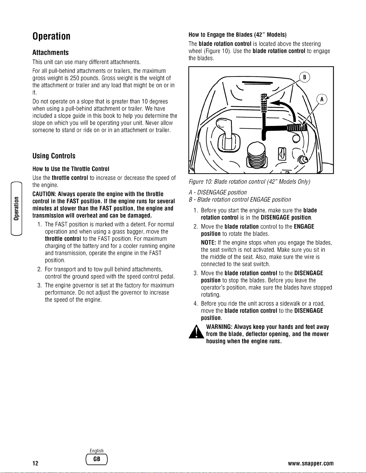
Howto Engagethe Blades(42" Models)
Theblade rotationcontrolis located abovethe steering
wheel (Figure10). Usethe blade rotationcontrolto engage
the blades.
I
I=
O
.B
z..,
o.
Using Controls
Howto UsetheThrottleControl
Usethe throttle controlto increaseor decreasethe speedof
the engine.
CAUTION:Alwaysoperatethe enginewith the throttle
controlin the FASTposition.If the enginerunsfor several
minutesat slowerthanthe FASTposition,the engine and
transmissionwill overheatand canbe damaged.
1. TheFASTposition is markedwith a detent. For normal
operation and when using a grass bagger, move the
throttlecontrolto the FASTposition. For maximum
charging of the battery and for a cooler runningengine
and transmission, operatethe engine in the FAST
position.
2. Fortransport and to tow pull behind attachments,
control the ground speedwith the speedcontrol pedal.
3. Theengine governor is set at the factory for maximum
performance. Donot adjust the governor to increase
the speedof the engine.
Figure 10:Bladerotation control (42" Models Only)
A - DISENGAGEposition
B - Bladerotation control ENGAGEposition
.
2.
.
.
Beforeyou start the engine, makesure the blade
rotationcontrolis in the DISENGAGEposition.
Move the blade rotationcontrol to the ENGAGE
positionto rotatethe blades.
NOTE:If the engine stops when you engagethe blades,
the seat switch is not activated.Make sure you sit in
the middle of the seat.Also, make surethe wire is
connectedto the seat switch.
Move the blade rotationcontrolto the DISENGAGE
positionto stop the blades. Beforeyou leavethe
operator's position, makesure the bladeshavestopped
rotating.
Beforeyou ride the unit across a sidewalkor a road,
move the blade rotationcontrolto the DISENGAGE
position.
WARNING:Alwayskeepyourhandsandfeet away
from the blade, deflectoropening,and the mower
housingwhen the engineruns.
12
English
www.snapper.com
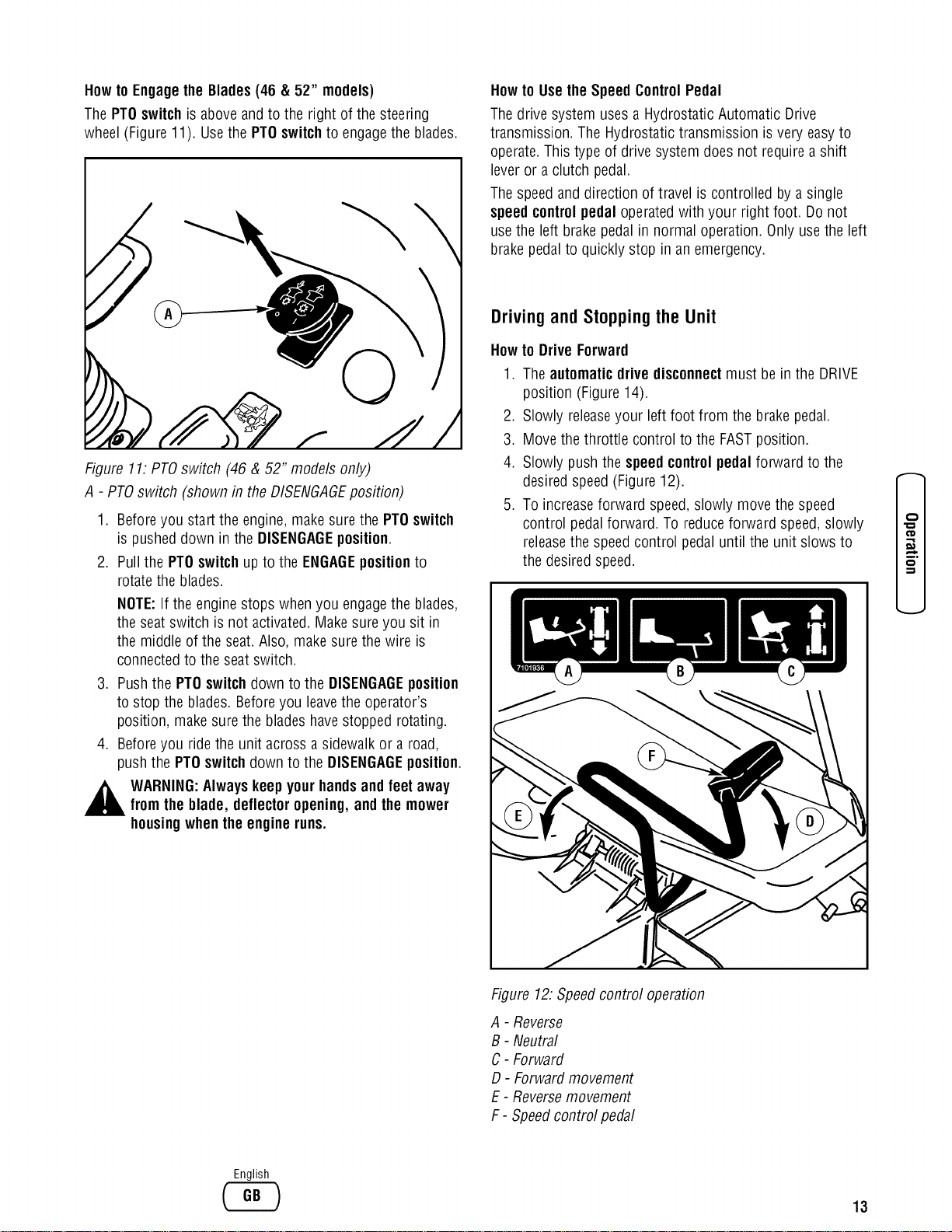
Howto Engagethe Blades(46 & 52" models)
The PTOswitchis aboveand to the right of the steering
wheel (Figure11). Usethe PTOswitchto engagethe blades.
©
\
Figure 11.PTOswitch (46 & 52" models only)
A - PTOswitch (shown in the DISENGAGEposition)
.
2.
.
.
Beforeyou start the engine,make sure the PTOswitch
is pusheddown inthe DISENGAGEposition.
Pullthe PTOswitchup to the ENGAGEpositionto
rotatethe blades.
NOTE:If the engine stops when you engagethe blades,
the seat switch is not activated. Makesure you sit in
the middle of the seat.Also, make surethe wire is
connectedto the seat switch.
Pushthe PTOswitchdown to the DISENGAGEposition
to stop the blades. Beforeyou leavethe operator's
position, make surethe bladeshavestopped rotating.
Beforeyou ride the unit across a sidewalk or a road,
push the PTOswitchdown to the DISENGAGEposition.
WARNING:Always keepyourhandsandfeet away
fromthe blade, deflectoropening,and the mower
housingwhenthe engineruns.
Howto Use the SpeedControlPedal
Thedrive system uses a Hydrostatic Automatic Drive
transmission. The Hydrostatic transmission is very easyto
operate.This type of drive system does not require a shift
lever or a clutch pedal.
Thespeedand direction of travel is controlled by a single
speedcontrolpedal operatedwith your right foot. Do not
usethe left brakepedal in normal operation. Only usethe left
brake pedalto quickly stop in an emergency.
Driving and Stopping the Unit
Howto Drive Forward
1. Theautomaticdrive disconnectmust be in the DRIVE
position (Figure14).
2. Slowly releaseyour leftfoot from the brakepedal.
3. Movethe throttle control to the FASTposition.
4. Slowly push the speedcontrolpedal forward to the
desired speed(Figure12).
5. To increaseforward speed,slowly move the speed
control pedalforward. To reduceforward speed,slowly
releasethe speed control pedal until the unit slows to
the desired speed.
o
Figure 12:Speedcontrol operation
A - Reverse
B - Neutral
C- Forward
D- Forward movement
E - Reversemovement
F - Speedcontrol pedal
English
13
e--
O
.B
€_
a,.,
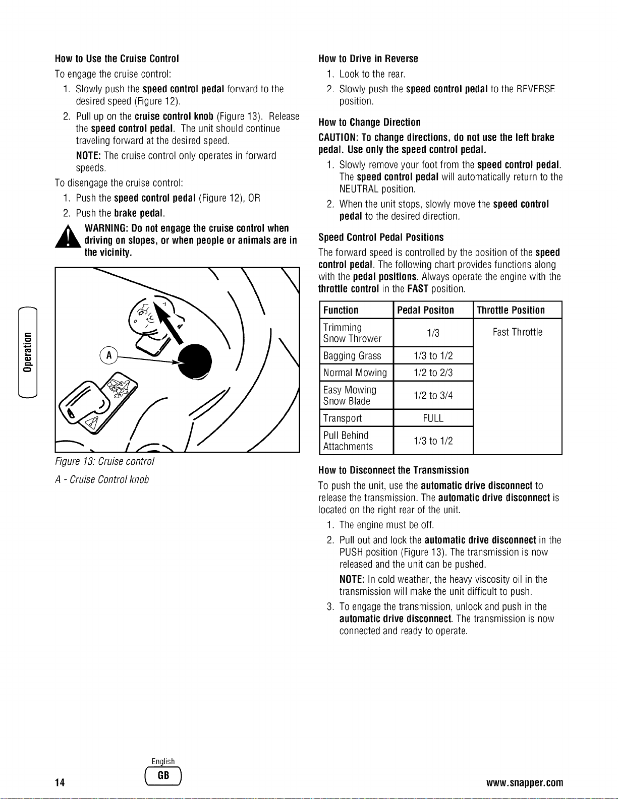
Howto Usethe CruiseControl
To engagethe cruise control:
1. Slowly push the speedcontrolpedal forward to the
desired speed(Figure12).
2. Pull up on the cruisecontrolknob(Figure13). Release
the speedcontrolpedal. Theunit should continue
traveling forward at the desiredspeed.
NOTE:The cruise control only operatesin forward
speeds.
To disengagethe cruise control:
1. Pushthe speedcontrolpedal (Figure12), OR
2. Pushthe brakepedal.
,_ WARNING:Do notengagethe cruisecontrolwhen
drivingon slopes,or whenpeopleor animalsare in
thevicinity.
\
Figure 13:Cruisecontrol
A - Cruise Control knob
Howto Drive in Reverse
1. Look to the rear.
2. Slowly push the speedcontrolpedal to the REVERSE
position.
Howto ChangeDirection
CAUTION:To changedirections,do not usetheleft brake
pedal. Useonlythespeed controlpedal.
1. Slowly removeyour foot from the speed controlpedal.
Thespeedcontrolpedal will automatically returnto the
NEUTRALposition.
2. Whenthe unit stops, slowly move the speed control
pedal to the desired direction.
SpeedControlPedal Positions
Theforward speedis controlled by the position of the speed
controlpedal. Thefollowing chart provides functions along
with the pedal positions.Always operatethe engine with the
throttlecontrolin the FASTposition.
Function
Trimming
Snow Thrower
Bagging Grass
Normal Mowing
EasyMowing
Snow Blade
Transport
Pull Behind
Attachments
Pedal Positon
1/3
1/3 to 1/2
1/2 to 2/3
1/2 to 3/4
FULL
1/3 to 1/2
ThrottlePosition
FastThrottle
Howto DisconnecttheTransmission
To push the unit, usethe automaticdrivedisconnectto
releasethe transmission. Theautomaticdrive disconnectis
locatedon the right rear of the unit.
1. Theengine must be off.
2. Pull out and lockthe automaticdrivedisconnectinthe
PUSHposition (Figure13). Thetransmission is now
releasedandthe unit can be pushed.
NOTE:In cold weather, the heavyviscosity oil in the
transmission will makethe unit difficult to push.
3. To engagethe transmission, unlock and push in the
automaticdrivedisconnect.The transmission is now
connectedand readyto operate.
14
English
www.snapper.com
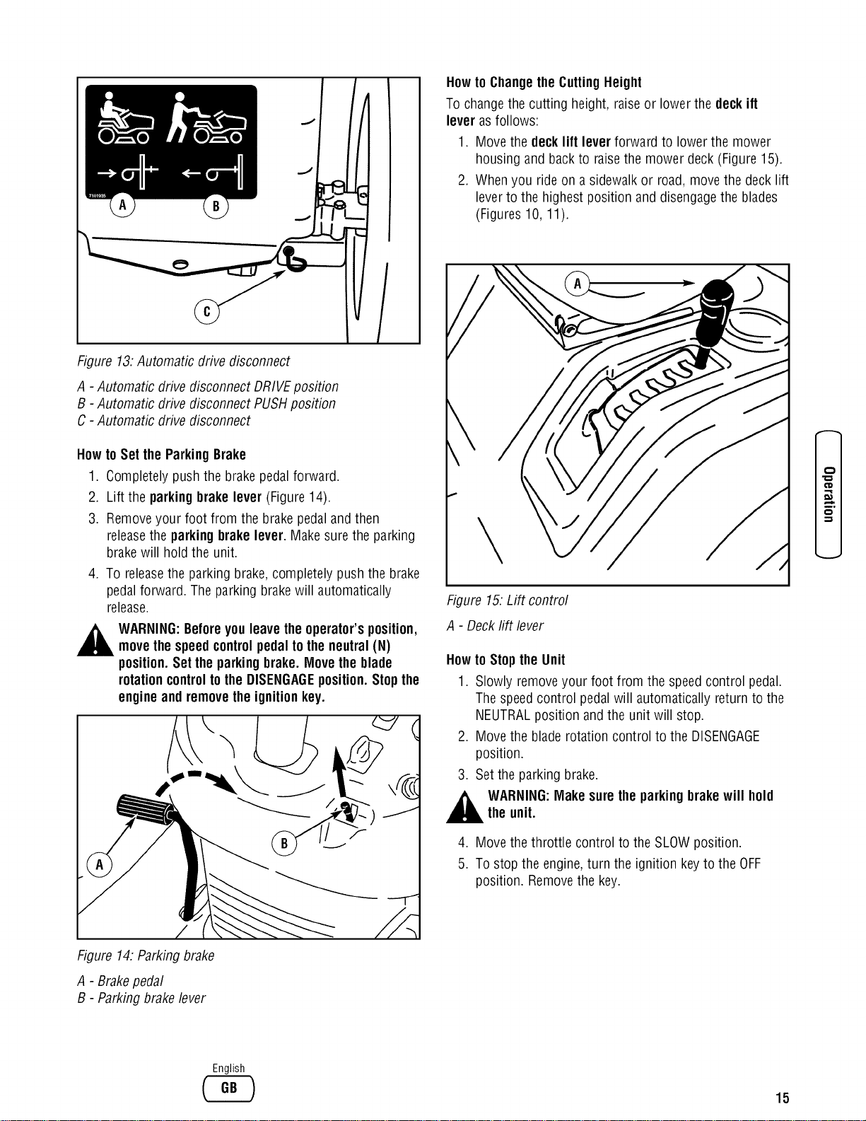
Figure 13.Automatic drive disconnect
A - Automatic drive disconnect DRIVEposition
B - Automatic drive disconnect PUSHposition
C - Automatic drive disconnect
How to Set the Parking Brake
1. Completely push the brakepedal forward.
2. Lift the parking brake lever (Figure14).
3. Removeyour foot from the brakepedal and then
releasethe parking brake lever. Make surethe parking
brakewill hold the unit.
4. To releasethe parking brake,completely push the brake
pedal forward. The parking brakewill automatically
release.
WARNING:Beforeyou leavethe operator'sposition,
movethespeedcontrolpedaltothe neutral(N)
position.Set theparkingbrake. Movethe blade
rotationcontroltothe DISENGAGEposition.Stopthe
engineand removethe ignitionkey.
Howto Changethe CuttingHeight
To changethe cutting height, raiseor lower the deck ift
lever as follows:
1. Move the deck lift lever forward to lower the mower
housing and backto raisethe mower deck (Figure 15).
2. Whenyou ride on a sidewalk or road,move the deck lift
leverto the highest position and disengagethe blades
(Figures 10, 11).
Figure 15.Lift control
A - Deckrift lever
Howto Stopthe Unit
1. Slowly removeyour foot from the speedcontrol pedal.
Thespeedcontrol pedalwill automatically return to the
NEUTRALposition and the unit will stop.
2. Move the bladerotationcontrol to the DISENGAGE
position.
3. Setthe parking brake.
,_ WARNING:Make sure theparking brakewill holdthe unit.
4. Move the throttle control to the SLOWposition.
5. To stop the engine,turn the ignition key to the OFF
position. Removethe key.
-.,z
o
-,,z
Figure 14.Parkingbrake
A - Brakepedal
B - Parkingbrake lever
English
15
0
.B
€_
x.,..
Row toTransportthe Unit
Totransport the unit, follow the steps below.
1. Disengagethe blades.
2. Raisethe deck lift leverto the highest position.
3. Move the throttle control to the FASTposition.
4. Slowly push the speedcontrol pedalforward to the
desired speed.
Mowing
Howto Operate the MowerDeck
,_ WARNING:The deflectoris a safety device. Donotremovethedeflector.The deflectorforcesthe
dischargedmaterial towardthe ground.Always
keepthedeflectorin the downposition.If the
deflectorisdamaged, replacethe deflectorwith an
originalequipmentpart froman authorizedservice
center.
1. Start the engine.
2. Releasethe parking brake.
3. Move the deck lift leverto a height of cut position. In
high or thick grass, cutthe grass in the highest
position first and then lower the mower deck to a lower
position.
CAUTION:Do notoperatewith the mowerdeckin the
LEVELADJUSTMENTposition.If youoperatein the LEVEL
ADJUSTMENTposition,the mowerdeckand bladescanbe
damaged.
4. Move the throttle control to the SLOWposition.
5. Engagethe blades.
6. Move the throttle control to the FASTposition.
7. Slowly push the speedcontrol pedalto the desired
speed.
NOTE:When you mow in heavygrass or mow with a
grass bagger,use a slow forward speed.
8. Make sure the levelof cut set at the factory is still
correct. After you mow a short distance, look at the
areathat was cut. If the mower deck does not cut level,
seethe instructions on "How To LevelThe Mower
Deck"in the Maintenancesection.
WARNING:Forbetter controlofthe unit, always
select a safe speed.
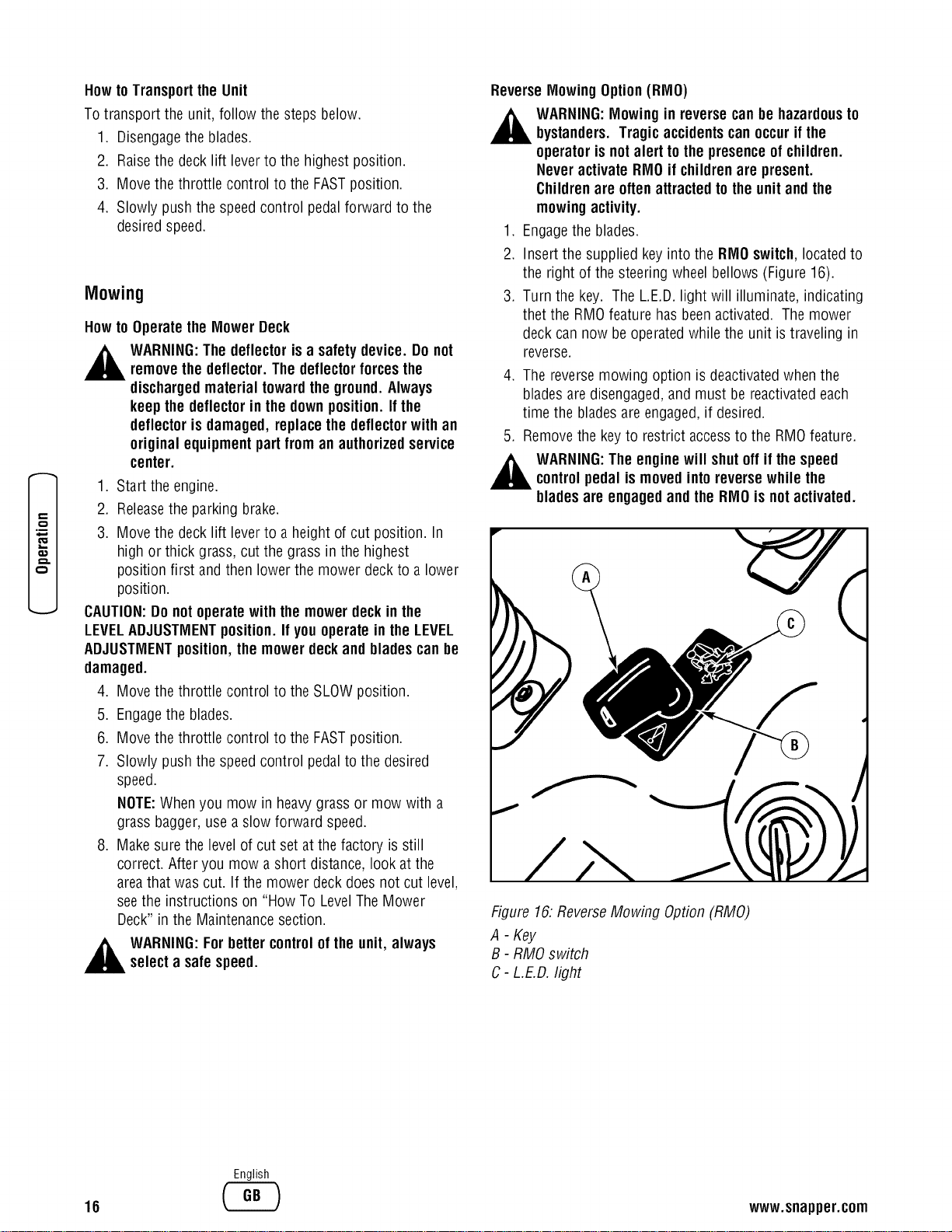
ReverseMowingOption(RMO)
WARNING:Mowingin reversecanbe hazardousto
bystanders.Tragic accidentscanoccurif the
operatoris notalert tothe presenceofchildren.
Neveractivate RIVIOif childrenare present.
Childrenare oftenattractedtothe unitand the
mowingactivity.
1. Engagethe blades.
2. Insert the supplied key into the RMOswitch,locatedto
the right of the steering wheel bellows (Figure 16).
3. Turn the key. The L.E.D.light will illuminate, indicating
thet the RMOfeature hasbeen activated. The mower
deck can now be operatedwhile the unit is traveling in
reverse.
,
,
The reversemowing option is deactivatedwhen the
bladesare disengaged,and must be reactivatedeach
time the bladesare engaged,if desired.
Removethe key to restrict accessto the RMOfeature.
WARNING:The enginewill shutoff if thespeed
controlpedal ismovedintoreversewhile the
bladesare engagedand the RMO isnot activated.
Figure 16:ReverseMowing Option (RMO)
A - Key
B - RMOswitch
C- L.E.D.light
16
English
www.snapper.com
Howto Operate the Unit on Hills
WARNING:Donot ride upor downslopesthatare
too steepto backstraightup. Never ride theunit
acrossa slope. See the "Slope Guide" in the back
ofthis bookfor informationon howto checkslopes.
1. Control the speedonly with the speed control pedal. Do
not usethe brake pedalon a hill.
2. To help prevent an accident, slowly move the speed
control pedal.Avoid suddenturns or changesin speed.
3. To reduceforward speedwhen going down a hill,
slowly releasethe speedcontrol pedal until the unit
slows to the desired speed.
Howto Stopon a Hill
1. Avoid stopping on a hill. If you must quickly stop in an
emergency, removeyour right foot from the speed
control pedaland quickly depress the left brakepedal.
2. Setthe parking brake.
3. Beforeyou dismount from the seat, move the throttle
control to SLOWposition, move the blade rotation
control to the DISENGAGEDposition, turn off the
engine and set the parking brake.
Howto Start Operationona Hill
1. Start the engine.
2. Move the bladerotation control to the ENGAGED
position.
3. Move the throttle control to the FASTposition.
4. Depressthe brake pedaland releasethe parking brake.
Asyou releasethe parking brake, pushthe speed
control pedalto the desiredspeed.
,_ WARNING:Slowlypushthe speedcontrolpedal as
you release the parkingbrake.The parkingbrake
mustbe disengagedbeforethespeed controlpedal
isable to engagethe transmission.
"o
-,z
=,1
o
-,,z
English
17
0
.B
€_
EngineOperation
BeforeStartingthe Engine
Checkthe Oil
NOTE:Theenginewas shipped from the factory filled with
oil. Checkthe level of the oil. Add oil as needed.Seethe
engine manufacturer's instructions for the type of gasoline
and oil to use.
1. Make sure the unit is level.
NOTE:Do not checkthe levelof the oil while the engine
runs.
2. Checkthe oil. Followthe procedurein the engine
manufacturer's instructions.
3. If necessary,add oil until the oil reachesthe FULLmark
on the dipstick. The quantity of oil neededfrom ADD to
FULL is shown on the dipstick. Donot add too much
oil.
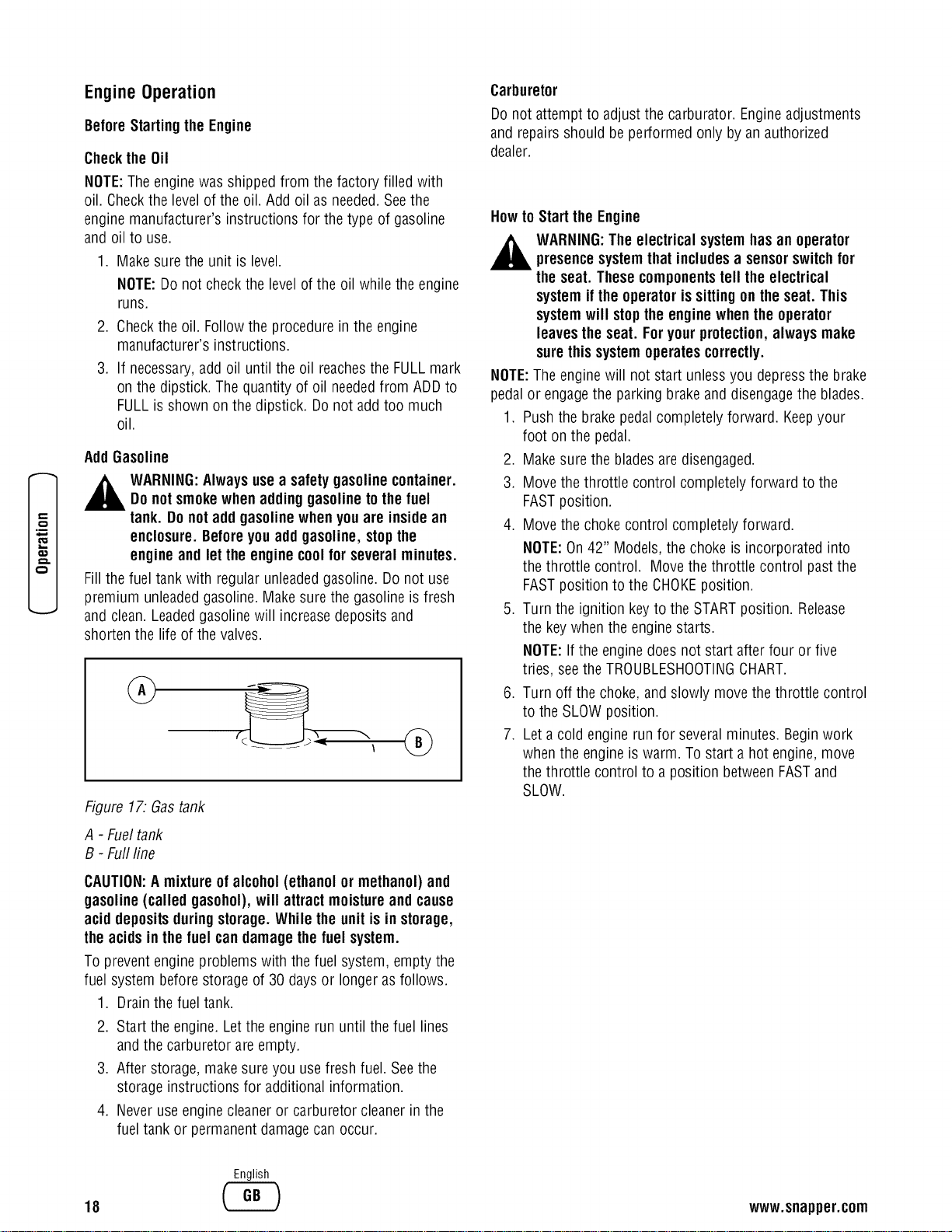
AddGasoline
,_ WARNING:Alwaysusea safety gasolinecontainer.
Donot smokewhen addinggasolinetothe fuel
tank. Do notadd gasolinewhenyouare insidean
enclosure.Beforeyouadd gasoline, stopthe
engineand let the enginecoolfor several minutes.
Fillthe fuel tank with regular unleadedgasoline. Do not use
premium unleadedgasoline. Makesure the gasoline is fresh
and clean. Leadedgasolinewill increasedeposits and
shorten the life of the valves.
Figure 17.Gastank
A - Fueltank
B - Fullfine
CAUTION:A mixtureofalcohol(ethanol or methanol)and
gasoline(called gasohol),will attractmoistureand cause
acid depositsduringstorage.While the unitis in storage,
theacids in the fuel can damagethefuel system.
To prevent engine problems with the fuel system, empty the
fuel system before storage of 30 daysor longer as follows.
1. Drainthe fuel tank.
2. Start the engine. Letthe engine run until the fuel lines
and the carburetor are empty.
3. After storage, makesure you use fresh fuel. Seethe
storage instructions for additional information.
4. Never useengine cleaneror carburetor cleanerin the
fuel tank or permanent damagecan occur.
Carburetor
Donot attempt to adjust the carburator. Engineadjustments
and repairsshould be performed only by an authorized
dealer.
Howto Startthe Engine
,_ WARNING:The electrical systemhasan operator
presencesystemthat includesa sensorswitchfor
the seat. These componentstell theelectrical
system ifthe operatorissittingon the seat. This
systemwill stopthe enginewhenthe operator
leavestheseat. Foryourprotection,always make
sure this systemoperatescorrectly.
NOTE:The enginewill not start unless you depress the brake
pedal or engagethe parking brake and disengagethe blades.
1. Push the brakepedal completely forward. Keepyour
foot on the pedal.
2. Make surethe bladesare disengaged.
3. Move the throttle control completely forward to the
FASTposition.
4. Move the choke control completely forward.
NOTE:On42" Models,the choke is incorporated into
the throttle control. Move the throttle control past the
FASTposition to the CHOKEposition.
5. Turn the ignition key to the STARTposition. Release
the key whenthe engine starts.
NOTE:If the engine does not start after four or five
tries, seethe TROUBLESHOOTINGCHART.
6. Turn off the choke, and slowly move the throttle control
to the SLOW position.
7. Let a cold engine run for several minutes. Beginwork
when the engine is warm. To start a hot engine,move
the throttle control to a position betweenFASTand
SLOW.
18
English
www.snapper.com
Tips
OperatingTips
1. Checkthe blade rotation control or the PTOclutch for
correct adjustment. Forthe bladesto disengage
correctly, the adjustment must be correct.
2. Beforeyou usethe unit, check the oil in the engine and
add oil if necessary.
3. If the engine will not start, first make surethe wire is
attachedto the spark plug.
4. Make sure all the belts are inside all the belt guides.
Seethe instructions on how to removeand install the
motion drive and mower drive belts.
5. Beforeyou makean inspection, adjustment (exceptfor
the carburetor), or repair, make surethe wire from the
spark plug is disconnected.
6. For longer life of the battery on electric start models,
chargethe batteryevery three months.
7. Usethe speedcontrol pedalto changethe ground
speed, not the throttle control.
8. Belt noise canoccur when the blade is engaged.This
noise is normal and does not affect the operationof the
unit.
Mowingand BaggingTips
1. Fora lawn to look better, checkthe cutting level of the
mower deck. See"How To LevelThe Mower Deck" in
the Maintenancesection.
2. Forthe mower deck to cut level, make sure the tires
havethe correct amount of air pressure.
3. Everytime you usethe unit, checkthe blade. If the
blade is bent or damaged, immediately replacethe
blade.Also, make surethe nut for the blade is tight.
4. Keepthe bladessharpened.Worn bladeswill causethe
ends of the grass to turn brown.
5. Do not cut or bag grass that is wet. Wet grass will not
discharge correctly. Letthe grass dry beforecutting.
6. Usethe left side of the mower deck to trim nearan
object.
7. Dischargethe cut grass onto the mowed area.The
result is a more evendischarge of cut grass.
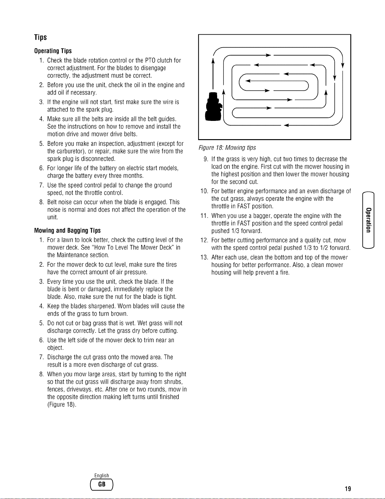
8. Whenyou mow large areas,start by turning to the right
so that the cut grass will discharge away from shrubs,
fences, driveways,etc. After one or two rounds, mow in
the opposite direction making left turns until finished
(Figure 18).
f
J
Figure 18:Mowing tips
9. If the grass is very high, cut two times to decreasethe
load on the engine. Firstcut with the mower housing in
the highest position and then lower the mower housing
for the second cut.
10. For better engine performance and an evendischarge of
the cut grass, alwaysoperatethe engine with the
throttle in FASTposition.
11. Whenyou usea bagger,operatethe engine with the
throttle in FASTposition andthe speedcontrol pedal
pushed 1/3 forward.
12. For better cutting performance and a quality cut, mow
with the speedcontrol pedal pushed 1/3 to 1/2 forward.
13. After eachuse, cleanthe bottom and top of the mower
housing for better performance. Also, a cleanmower
housing will help prevent a fire.
-.,z
o
-,,z
English
19
,E
Maintenance
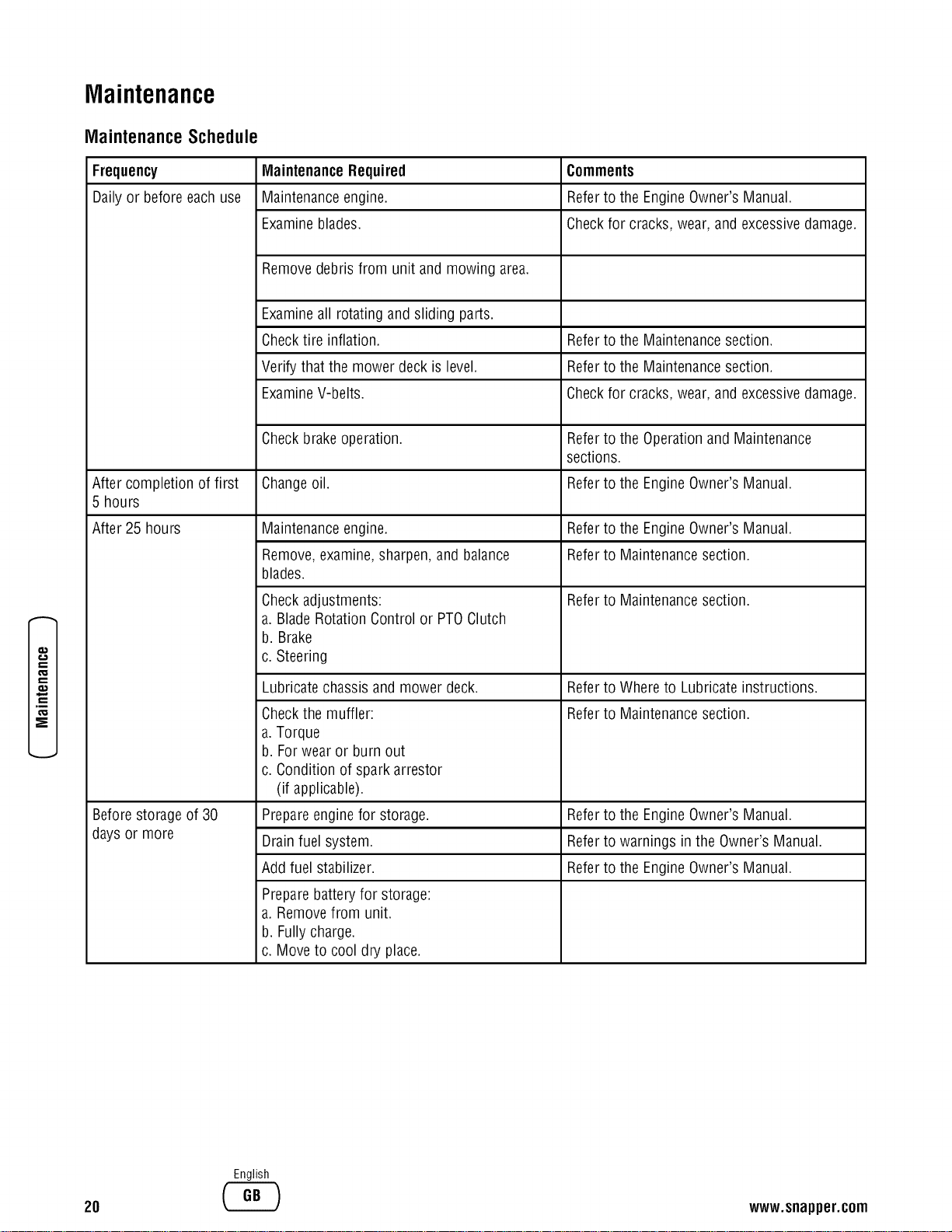
MaintenanceSchedule
Frequency MaintenanceRequired Comments
Dailyor before eachuse Maintenanceengine. Referto the EngineOwner's Manual.
Examineblades. Checkfor cracks, wear, and excessivedamage.
Removedebris from unit and mowing area.
Examineall rotating and sliding parts.
Checktire inflation. Referto the Maintenancesection.
Verify that the mower deck is level. Referto the Maintenancesection.
ExamineV-belts. Checkfor cracks, wear, and excessivedamage.
Checkbrakeoperation. Referto the Operationand Maintenance
sections.
After completion of first Changeoil. Referto the EngineOwner's Manual.
5 hours
After 25 hours Referto the EngineOwner's Manual.
Referto Maintenancesection.
Referto Maintenancesection.
Referto Whereto Lubricate instructions.
Referto Maintenancesection.
Maintenanceengine.
Remove,examine,sharpen, and balance
blades.
Checkadjustments:
a. Blade RotationControl or PTOClutch
b. Brake
c. Steering
Lubricate chassis and mower deck.
Checkthe muffler:
a.Torque
b. Forwear or burn out
c. Condition of spark arrestor
(if applicable).
Prepareengine for storage.
Drain fuel system.
Add fuel stabilizer.
Prepare batteryfor storage:
a. Removefrom unit.
b. Fullycharge.
c. Move to cool dry place.
Beforestorage of 30 Referto the EngineOwner's Manual.
days or more Referto warnings in the Owner's Manual.
Referto the EngineOwner's Manual.
20
English
www.snapper.com
GeneralRecommendations
1. Theowner's responsibility is to maintain this product.
This will extendthe life of the product and is also
necessaryto maintainwarrantycoverage.
2. Checkthe sparkplug, drive brake, lubricate the unit,
and cleanthe air filter oncea year.
3. Checkthe fasteners. Make sure all fasteners are tight.
4. Follow the Maintenancesection to keepthe unit in good
operating condition.
,_ WARNING:Beforeyou make an inspection,
adjustment,or repair to the unit, disconnectthe
wire tothe sparkplug. Removethewire from the
sparkplug to prevent theengine from starting by
accident.
NOTE:Torque is measuredin foot pounds (metric Nm). This
measurement describeshow tight a nut or bolt must be.The
torque is measuredwith atorque wrench.
Inspection
Howto Checkthe Muffler
Checkthe muffler every50 hours. Makesurethe muffler is
correctly mounted and is not loose. If the muffler is worn or
burnt, replacewith a new muffler. A worn muffler is a fire
hazardand can also damagethe engine.
If you mount a spark arrester to the muffler, also checkthe
spark attester when you checkthe muffler. If the spark
attester isworn or damaged,replaceit with a newspark
attester. Seeyour nearestauthorized service centerfor a
spark attester.
InspectBlade
WARNING:Beforeyouinspectorremovetheblade,
disconnectthewiretothesparkplug. Ifthebladehits
an object,stoptheengine.Checktheunitfor
damage.The bladehassharpedges.Whenyouhold
theblade, useglovesor clothmaterialtoprotectyour
hands.
If you keepthe bladesharp and inspectthe bladefor
damage,the bladewill cut better and be more safe to
operate. Frequentlycheckthe blade for excessivewear,
cracks, or other damage. Frequentlycheck the nut that holds
the blade. Keepthe nut tight. If the bladehits an object, stop
the engine. Disconnectthe wire to the spark plug. Seeif the
blade is bentor damaged. Checkthe blade adapterfor
damage. Beforeyou operatethe unit, replacedamagedparts
with original equipment parts. Seethe authorized service
center in your area.Everythree years, havean authorized
service person inspectthe bladeor replacethe old bladewith
an original equipment part.
Howto Removeand Install the Blade
1. Removethe mower housing. Seethe instructions on
"How To RemoveThe Mower Housing".
2. Use a pieceof wood to keepthe bladefrom rotating.
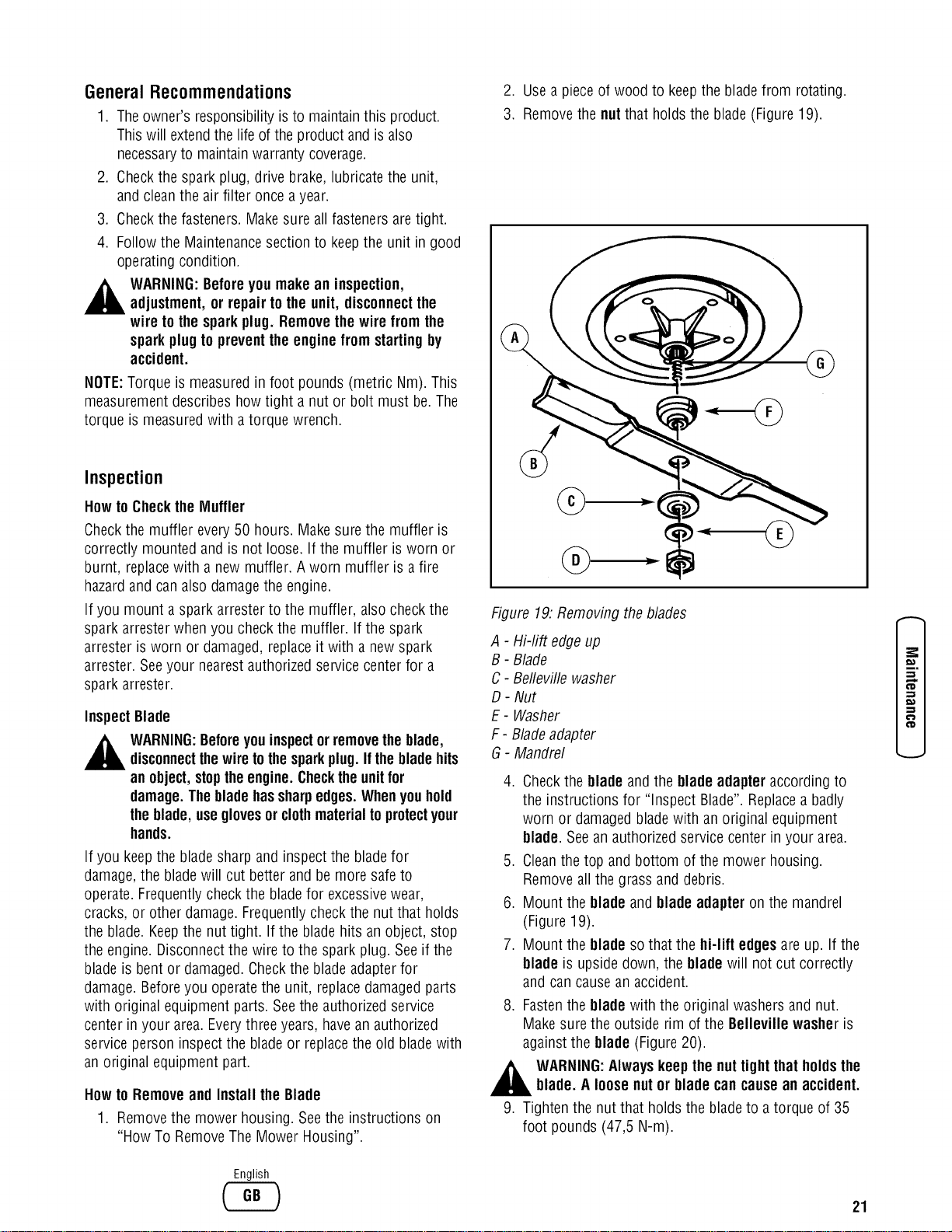
3. Removethe nutthat holdsthe blade(Figure19).
@
Figure 19:Removing theblades
A - Hi-lift edgeup
B - Blade
C- Bellevillewasher
D- Nut
E- Washer
F - Bladeadapter
G- Mandrel
.
.
6.
7.
,
.
Checkthe blade and the blade adapteraccording to
the instructions for "Inspect Blade". Replacea badly
worn or damagedbladewith an original equipment
blade. Seean authorized service center in your area.
Cleanthe top and bottom of the mower housing.
Removeall the grass and debris.
Mount the blade and bladeadapteron the mandrel
(Figure 19).
Mount the blade sothat the hi-lift edgesare up. If the
blade is upside down, the bladewill not cut correctly
and can causean accident.
Fastenthe blade with the original washers and nut.
Make surethe outside rim of the Belleville washer is
against the blade (Figure20).
WARNING:Alwayskeepthe nuttightthat holdsthe
blade. A loosenutor blade cancauseanaccident.
Tighten the nut that holds the bladeto a torque of 35
foot pounds (47,5 N-m).
CD
English
21
.E
_E
10. Install the mower deck.See"How To Install The Mower
Deck".
.
A newblade will cut better than a badlyworn blade.
Everythree years, havean authorizedservice person
inspect the blade or replacethe old blade with an
original equipment blade.
S
I
D. ©
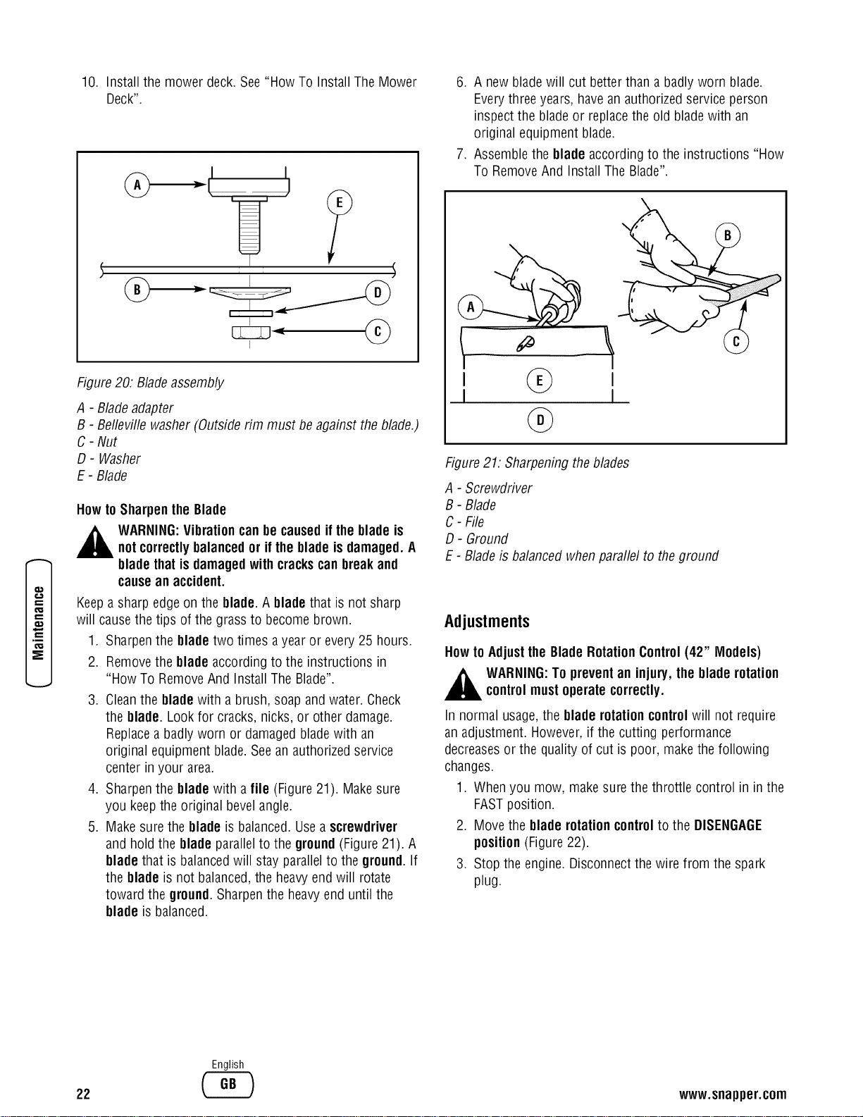
Figure20. Bladeassembly
A - Bladeadapter
7. Assemblethe blade according to the instructions "How
To RemoveAnd Install The Blade".
B - Belleville washer(Outside nm must be against the blade.)
C - Nut
D- Washer
E - Blade
How to Sharpenthe Blade
,_ WARNING:Vibrationcanbe causedif the bladeis
notcorrectlybalancedor if the bladeis damaged.A
bladethatis damagedwith crackscanbreakand
causeanaccident.
Figure21: Sharpening theblades
A - Screwdriver
B - Blade
C- File
D- Ground
E - Blade is balancedwhenparallel to the ground
Keepa sharp edge on the blade. A bladethat is not sharp
will causethe tips of the grass to become brown.
1. Sharpenthe bladetwo times ayear or every 25 hours.
2. Removethe bladeaccording to the instructions in
"How To RemoveAnd Install The Blade".
3. Cleanthe blade with a brush, soap and water. Check
the blade. Lookfor cracks, nicks, or other damage.
Replacea badly worn or damagedbladewith an
original equipment blade.Seean authorized service
center in your area.
4. Sharpenthe bladewith a file (Figure21). Makesure
you keepthe original bevelangle.
5. Make surethe blade is balanced. Usea screwdriver
and hold the blade parallelto the ground (Figure 21). A
bladethat is balancedwill stay parallelto the ground.If
the blade is not balanced,the heavyend will rotate
toward the ground. Sharpenthe heavyend until the
blade is balanced.
Adjustments
Howto Adjustthe BladeRotationControl(42" Models)
,_ WARNING:To preventan injury, the blade rotation
controlmustoperatecorrectly.
In normal usage,the bladerotationcontrolwill not require
an adjustment. However,if the cutting performance
decreasesor the quality of cut is poor, makethe following
changes.
1. Whenyou mow, makesure the throttle control in in the
FASTposition.
2. Move the blade rotationcontrolto the DISENGAGE
position(Figure22).
3. Stop the engine. Disconnectthe wire from the spark
plug.
22
English
www.snapper.com
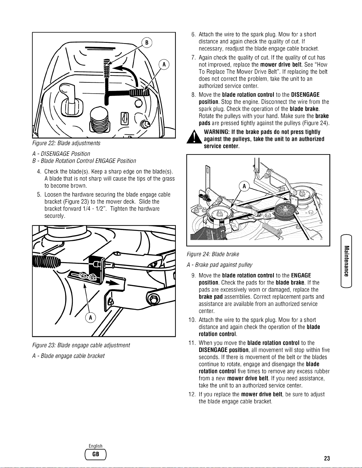
Figure22: Bladeadjustments
A - DISENGAGEPosition
B - BladeRotation Control ENGAGEPosition
4. Checkthe blade(s). Keepa sharp edge on the blade(s).
A bladethat is not sharpwill causethe tips ofthe grass
to become brown.
5. Loosenthe hardwaresecuring the bladeengagecable
bracket (Figure23) to the mower deck. Slide the
bracketforward 1/4 - 1/2". Tighten the hardware
securely.
Figure23. Bladeengagecableadjustment
A - Bladeengagecablebracket
.
.
.
Attach thewire to the spark plug. Mow for a short
distance and again checkthe quality of cut. If
necessary,readjust the blade engagecable bracket.
Again checkthe quality of cut. If the quality of cut has
not improved, replacethe mower drive belt. See"How
To ReplaceThe Mower Drive Belt". If replacingthe belt
does not correct the problem, take the unit to an
authorized servicecenter.
Move the blade rotationcontrolto the DISENGAGE
position. Stop the engine. Disconnectthe wire from the
spark plug. Checkthe operationof the blade brake.
Rotatethe pulleys with your hand. Makesure the brake
pads are pressed tightly against the pulleys (Figure24).
WARNING:If the brake pads donot press tightly
againstthe pulleys,take the unittoan authorized
service center.
Figure24. Bladebrake
A - Brakepad againstpulley
. Move the blade rotationcontrolto the ENGAGE
position. Checkthe padsfor the blade brake.If the
pads areexcessively worn or damaged,replacethe
brake pad assemblies.Correct replacementparts and
assistanceare availablefrom an authorized service
center.
10.
11.
Attach thewire to the spark plug. Mow for a short
distance and again checkthe operation of the blade
rotationcontrol.
Whenyou move the blade rotationcontrolto the
DISENGAGEposition,all movement will stop within five
seconds. If there is movement of the belt or the blades
continue to rotate,engageand disengagethe blade
rotationcontrolfive times to removeany excess rubber
from a new mowerdrive belt. Ifyou needassistance,
take the unit to an authorized service center.
12. If you replacethe mowerdrivebelt, be sure to adjust
the blade engagecablebracket.
CD
-q
':D
English
23
,E
E
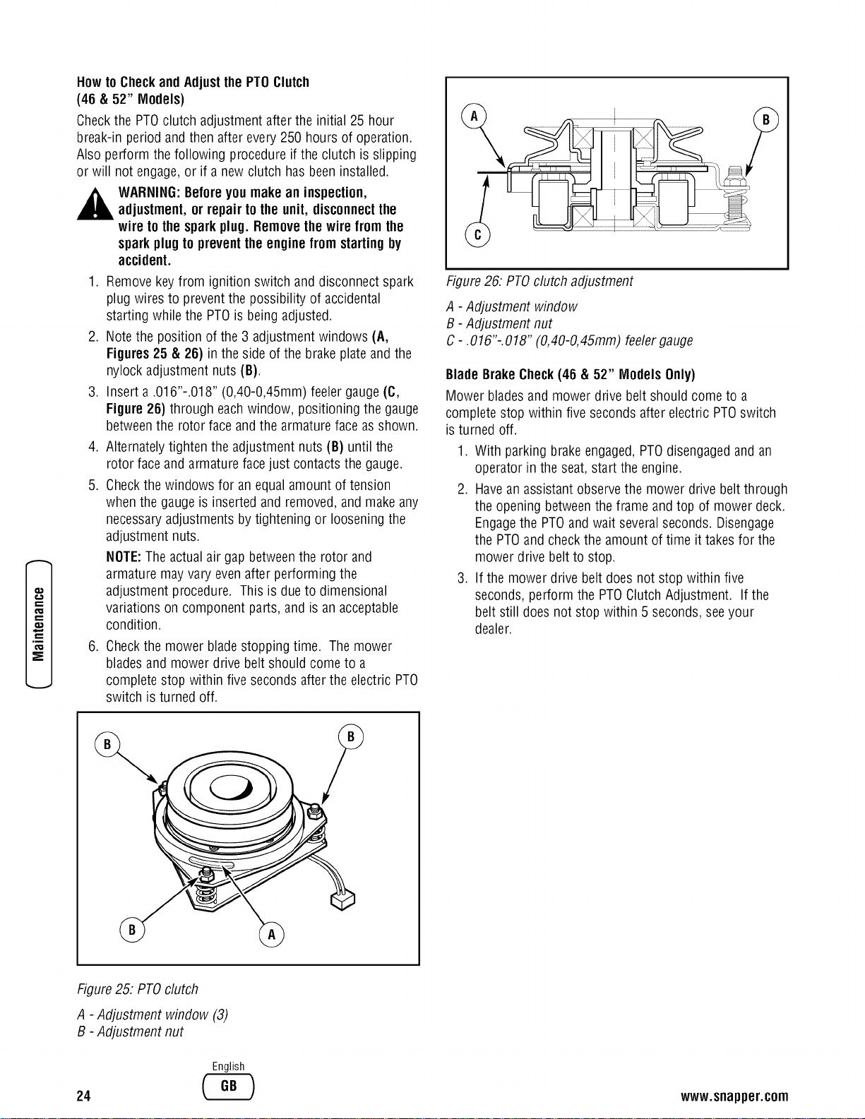
Howto Checkand Adjustthe PTOClutch
(46 & 52" Models)
Checkthe PTOclutch adjustment after the initial 25 hour
break-in period and then after every 250 hours of operation.
Also perform the following procedure if the clutch is slipping
or will not engage,or if a new clutch has beeninstalled.
,_ WARNING:Beforeyou make an inspection,
adjustment,or repair to the unit, disconnectthe
wire tothe sparkplug. Removethewire from the
sparkplug to preventtheengine fromstarting by
accident.
1. Removekey from ignition switch and disconnect spark
plug wires to preventthe possibility of accidental
starting while the PTOis being adjusted.
2. Note the position of the 3 adjustment windows (A,
Figures25 & 26) in the side of the brakeplate and the
nylock adjustment nuts (B}.
3. Insert a.016"-.018" (0,40-0,45mm) feelergauge (C,
Figure 26) through eachwindow, positioning the gauge
betweenthe rotor face andthe armaturefaceasshown.
4. Alternatelytighten the adjustment nuts (B) until the
rotor face and armature face just contactsthe gauge.
5. Checkthe windows for an equal amount of tension
when the gauge is inserted and removed,and make any
necessaryadjustments by tightening or loosening the
adjustment nuts.
NOTE:The actualair gap betweenthe rotor and
armature mayvary evenafter performing the
adjustment procedure. This is due to dimensional
variations on component parts, and is an acceptable
condition.
6. Checkthe mower bladestopping time. Themower
bladesand mower drive belt should come to a
complete stop within five seconds after the electric PTO
switch is turned off.
Figure26: PTOclutch adjustment
A - Adjustment window
B - Adjustment nut
C-. 016"-.018" (0,40-0,45mm) feelergauge
BladeBrakeCheck(46 & 52" Models Only)
Mower bladesand mower drive belt should come to a
complete stop within five seconds after electric PTOswitch
is turned off.
1. With parking brakeengaged,PTOdisengagedand an
operator in the seat,start the engine.
2. Havean assistant observethe mower drive belt through
the opening betweenthe frame and top of mower deck.
Engagethe PTOand wait severalseconds. Disengage
the PTOand checkthe amount of time ittakes for the
mower drive belt to stop.
3. If the mowerdrive belt doesnot stop within five
seconds, perform the PTOClutchAdjustment. If the
belt still does not stop within 5 seconds, seeyour
dealer.
Figure25: PTOclutch
A - Adjustment window (3)
B - Adjustment nut
24
English
www.snapper.com
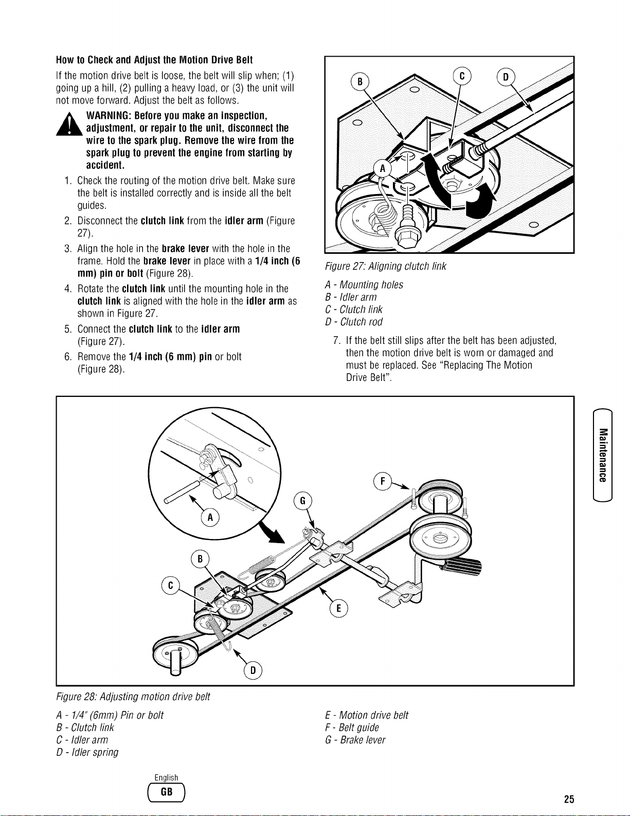
Howto Checkand Adjustthe MotionDriveBelt
If the motion drive belt is loose, the belt will slip when; (1)
going up a hill, (2) pulling a heavyload, or (3) the unit will
not move forward. Adjust the belt asfollows.
,_ WARNING:Beforeyou make an inspection,
adjustment,or repair to the unit, disconnectthe
wire tothe sparkplug. Removethewire from the
sparkplug to preventtheengine fromstarting by
accident.
1. Checkthe routing of the motion drive belt. Makesure
the belt is installed correctly and is inside all the belt
guides.
2. Disconnectthe clutchlinkfrom the idler arm (Figure
27).
3. Align the holein the brake lever with the hole in the
frame. Hold the brake lever in placewith a 1/4 inch (6
mm} pinor bolt (Figure28).
4. Rotatethe clutchlink until the mounting hole in the
clutchlink is aligned with the hole in the idler arm as
shown in Figure27.
5. Connectthe clutchlink to the idler arm
(Figure 27).
6. Removethe 1/4 inch (6 mm) pin or bolt
(Figure 28).
Figure27: Aligning clutch link
A - Mounting holes
B - Idler arm
C- Clutchlink
D- Clutch rod
.
If the belt still slips after the belt has beenadjusted,
thenthe motion drive belt is worn or damagedand
must be replaced.See "Replacing The Motion
Drive Belt".
¢'D
Figure28: Adjusting motion drive belt
A - 1/4"(6mm) Pin or bolt
B - Clutchlink
C - Idler arm
D - Idler spring
English
E - Motion drive belt
F - Beltguide
G- Brakelever
25
,E
_E
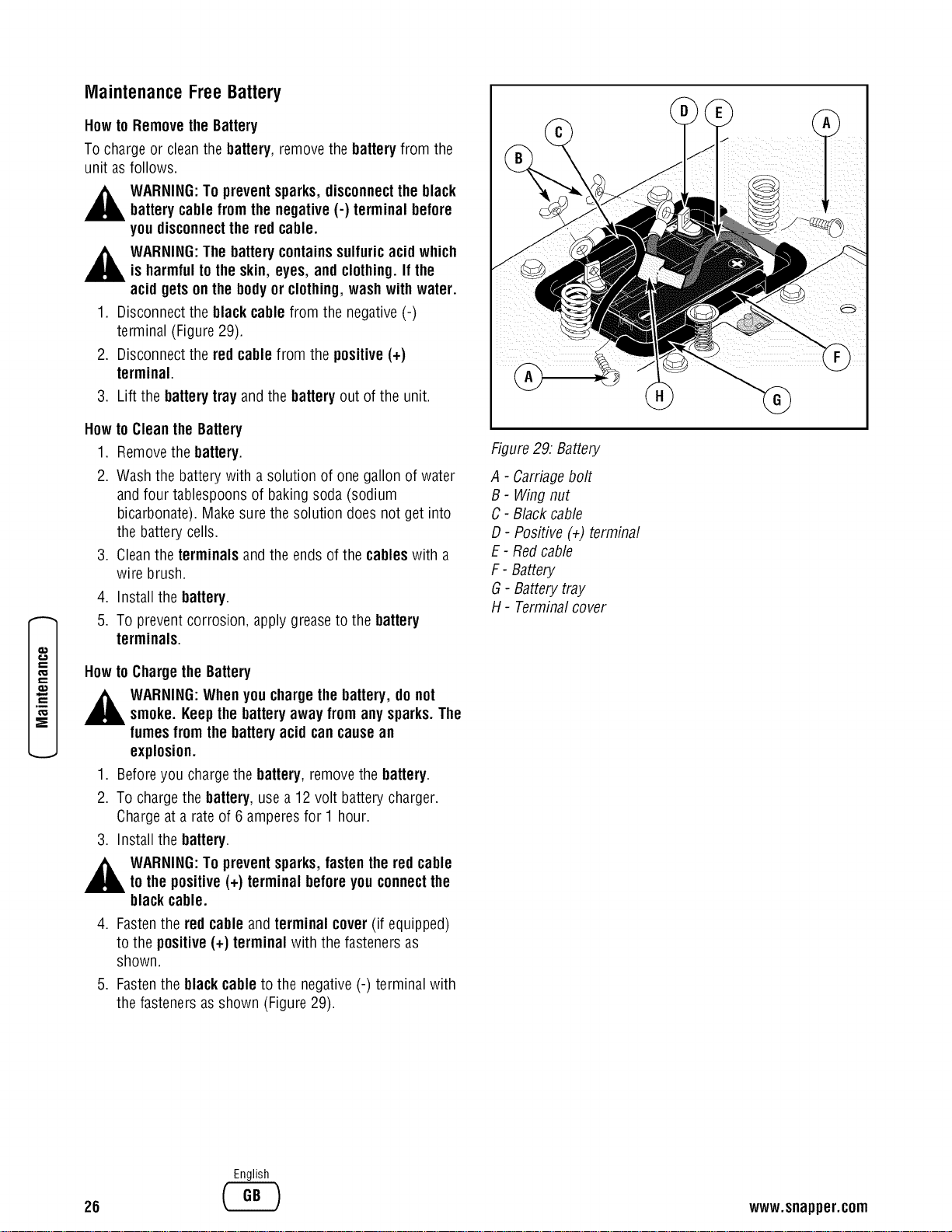
MaintenanceFreeBattery
Howto Removethe Battery
To chargeor cleanthe battery, removethe batteryfrom the
unit asfollows.
,_ WARNING:To prevent sparks,disconnectthe black
batterycablefrom the negative(-) terminal before
you disconnectthe red cable.
WARNING:The batterycontainssulfuricacid which
is harmfultothe skin, eyes, and clothing.If the
acid getsonthe bodyor clothing,washwith water.
1. Disconnectthe blackcable from the negative(-)
terminal (Figure29).
2. Disconnectthe red cablefrom the positive(+)
terminal.
3. Liftthe batterytray and thebatteryout of theunit,
How
1.
2.
.
4.
5,
to Cleanthe Battery
Removethe battery.
Wash the battery with a solution of one gallon of water
and four tablespoons of baking soda (sodium
bicarbonate). Make surethe solution does not get into
the battery cells,
Cleanthe terminals and the ends of the cableswith a
wire brush.
Install the battery.
To prevent corrosion, apply greaseto the battery
terminals.
Howto Chargethe Battery
,_ WARNING:Whenyou chargethe battery,do not
smoke. Keepthe batteryaway from anysparks.The
fumesfrom the batteryacid cancausean
explosion.
.
2.
Beforeyou chargethe battery,removethe battery.
To chargethe battery,usea 12 volt batterycharger.
Chargeata rateof 6 amperesfor 1 hour.
3. Install the battery.
,_ WARNING:To preventsparks,fastenthered cable
to the positive(+) terminal beforeyouconnectthe
blackcable.
4. Fastenthe red cable and terminal cover(if equipped)
to the positive(+) terminal with the fasteners as
shown.
5. Fastenthe black cableto the negative (-) terminal with
the fasteners asshown (Figure 29).
Figure29: Battery
A - Carriagebolt
B - Wing nut
C- Black cable
D- Positive (+1)terminal
E - Redcable
F- Battery
G- Battery tray
H- Terminalcover
26
English
www.snapper.com
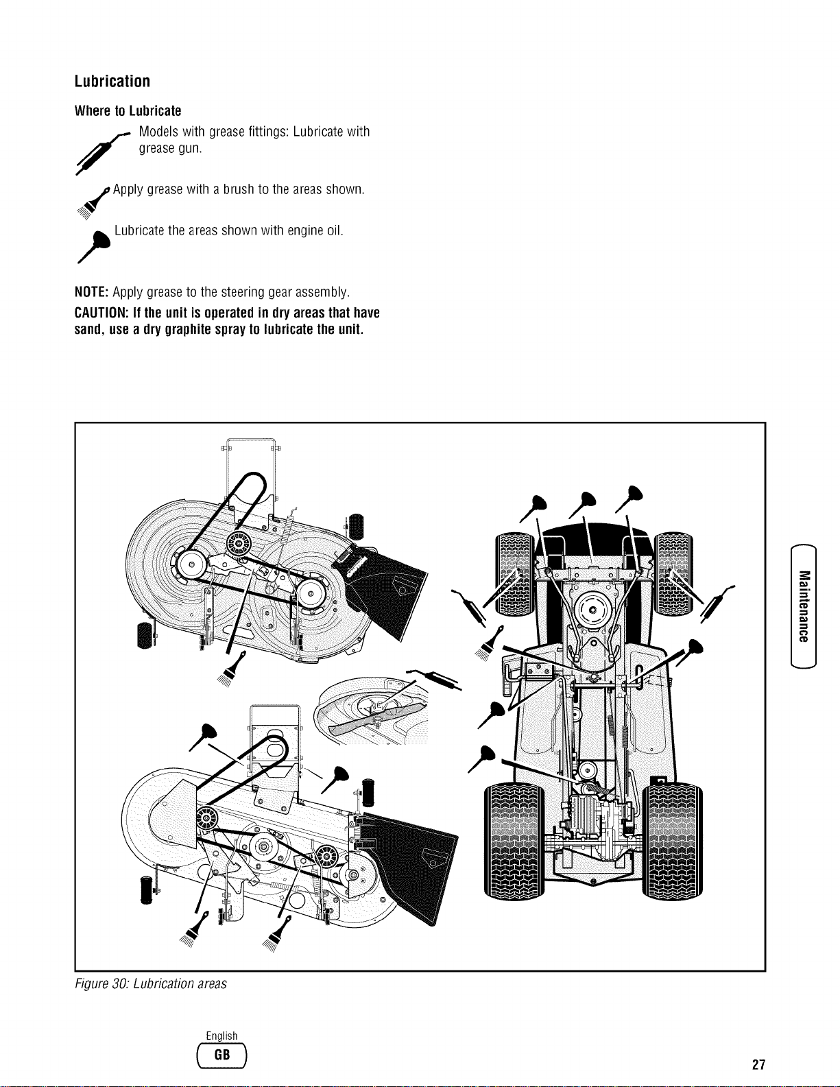
Lubrication
Whereto Lubricate
Models with greasefittings: Lubricatewith
f greasegun.
%%_Apply greasewith a brushto the areasshown.
,,_ Lubricatethe areasshown with engineoil.
NOTE:Apply greaseto the steering gear assembly.
CAUTION:If theunit is operatedin dry areasthat have
sand,usea dry graphitesprayto lubricatetheunit.
¢D
€'D
Figure30. Lubrication areas
English
27
.E
_E
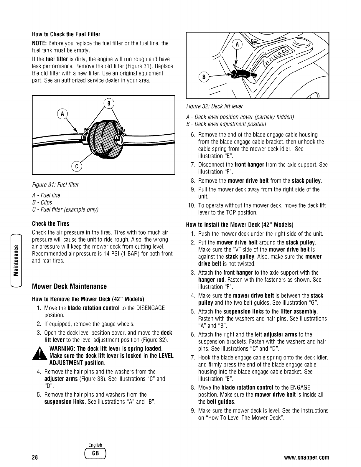
Howto Checkthe Fuel Filter
NOTE:Beforeyou replacethe fuel filter or the fuel line, the
fuel tank must be empty.
If the fuel filter is dirty, the engine will run rough and have
less performance. Removethe old filter (Figure31). Replace
the old filter with a new filter. Usean original equipment
part. Seean authorizedservice dealerin your area.
Figure31: Fuelfilter
A - Fuelline
B- Clips
C - Fuelfilter (example only)
ChecktheTires
Checkthe air pressure in the tires. Tires with too much air
pressure will causethe unit to ride rough. Also, thewrong
air pressure will keepthe mower deck from cutting level.
Recommendedair pressure is 14 PSI(1 BAR)for both front
and reartires.
MowerDeckMaintenance
Howto Removethe Mower Deck(42" Models)
1. Move the blade rotationcontrolto the DISENGAGE
position.
2. If equipped, removethe gaugewheels.
3. Openthe deck levelposition cover, and move the deck
lift lever to the leveladjustment position (Figure32).
,_ WARNING:The decklift lever isspringloaded.Makesure the decklift lever is lockedin the LEVEL
ADJUSTMENTposition.
4. Removethe hair pins and the washersfrom the
adjusterarms (Figure33). See illustrations "C" and
_D _"
5. Removethe hair pins and washers from the
suspensionlinks. Seeillustrations "A" and "B".
Figure32: Deckrift lever
A - Decklevelposition cover (partially hidden)
B - Deckleveladjustment position
6. Removethe end of the bladeengage cablehousing
from the bladeengagecable bracket,then unhook the
cablespring from the mower deck idler. See
illustration "E".
7. Disconnectthe fronthangerfrom the axlesupport. See
illustration "F".
8. Removethe mowerdrive belt from thestackpulley.
9. Pull the mower deck awayfrom the right side of the
unit.
10. To operatewithout the mower deck, move the deck lift
leverto the TOPposition.
Howto Install the Mower Deck(42" Models)
1. Push the mower deck under the right side of the unit.
2. Put the mower drivebelt around the stack pulley.
Make surethe "V" side of the mower drivebelt is
against the stackpulley.Also, makesure the mower
drivebelt isnot twisted.
3. Attachthe fronthangerto the axlesupport with the
hangerrod. Fastenwith the fasteners as shown. See
illustration "F".
4. Make sure the mowerdrive belt is betweenthe stack
pulley and the two belt guides. Seeillustration "G".
5. Attach thesuspensionlinks to the lifter assembly.
Fastenwith thewashers and hair pins. Seeillustrations
"A" and "B".
6. Attach the right and the left adjusterarmsto the
suspension brackets.Fastenwith the washers and hair
pins. Seeillustrations "C" and "D".
7. Hook the blade engagecablespring onto the deck idler,
and firmly press the end of the bladeengagecable
housing into the blade engagecablebracket. See
illustration "E".
8. Move the blade rotationcontrolto the ENGAGE
position. Make surethe mowerdrive belt is inside all
the belt guides.
9. Make sure the mower deck is level.Seethe instructions
on "How To LevelThe Mower Deck".
28
English
www.snapper.com
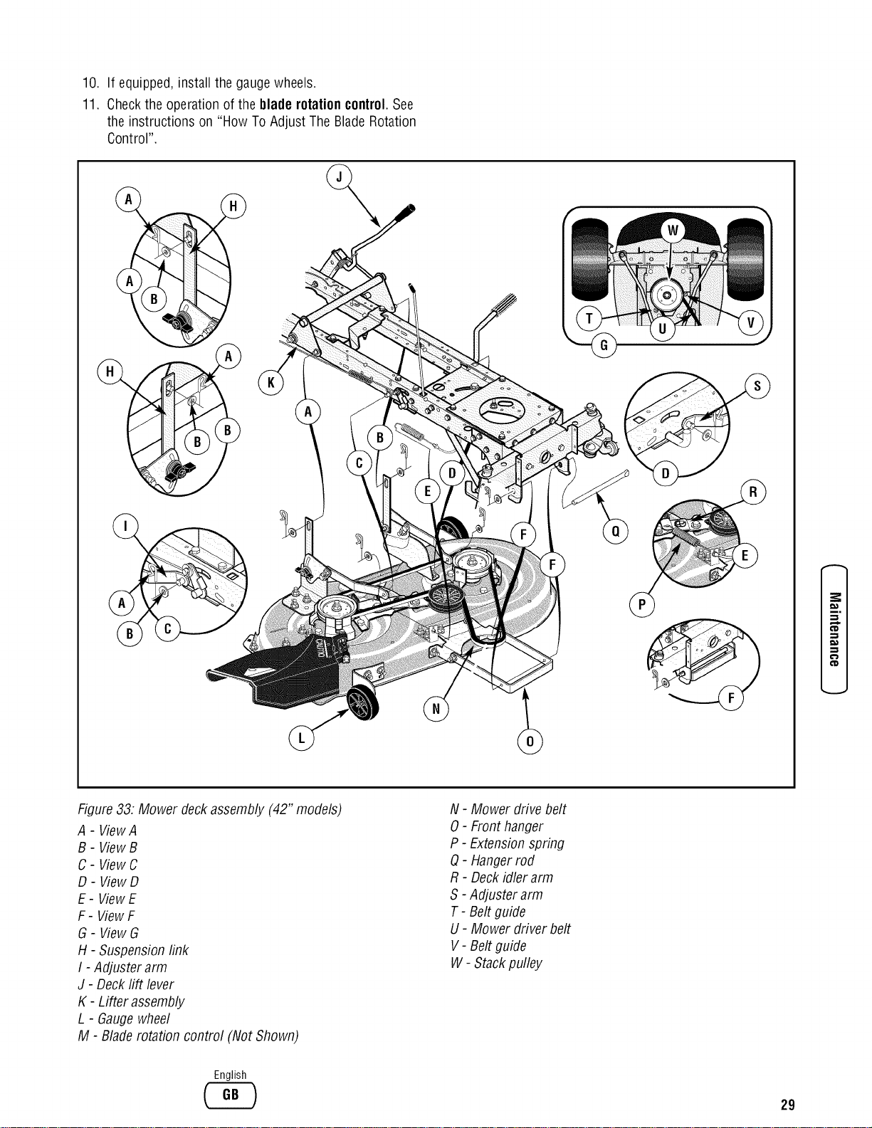
10.
11.
If equipped, install the gaugewheels.
Checkthe operationof the blade rotationcontrol.See
the instructions on "How To Adjust The BladeRotation
Control".
¢D
€ID
Figure33: Mower deckassembly (42" models)
A - ViewA
B- ViewB
C- ViewC
D- ViewD
E- ViewE
F- ViewF
G- ViewG
H - Suspension link
I - Adjuster arm
J - Decklift lever
K - Lifter assembly
L - Gaugewheel
M - Blade rotation control (Not Shown)
N- Mower drive belt
0 - Front hanger
P - Extensionspring
Q- Hangerrod
R- Deckidler arm
S- Adjuster arm
T- Belt guide
U- Mower driver belt
V - Beltguide
W - Stackpulley
English
29
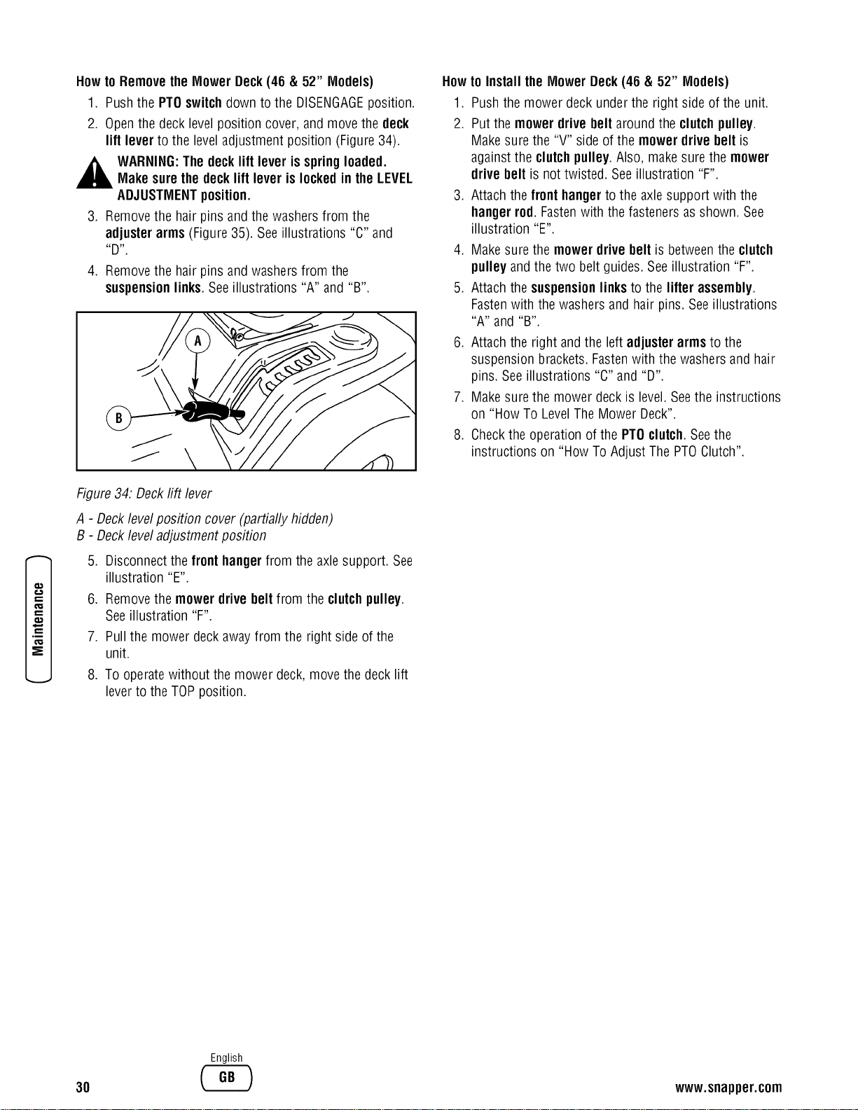
Howto Removethe Mower Deck(46 & 52" Models)
1. Pushthe PTOswitchdown to the DISENGAGEposition.
2. Openthe deck levelposition cover, and movethe deck
lift lever to the leveladjustment position (Figure34).
WARNING:The decklift lever isspringloaded.
Makesure the decklift lever is lockedin the LEVEL
ADJUSTMENTposition.
3. Removethe hair pins and the washersfrom the
adjuster arms (Figure35). See illustrations "C" and
_D _"
4. Removethe hair pins and washers from the
suspensionlinks. Seeillustrations "A" and "B".
Howto Install the Mower Deck(46 & 52" Models)
1. Push the mower deck under the right side of the unit.
2. Put the mower drivebelt around the clutchpulley.
Make surethe "V" side of the mower drivebelt is
against the clutchpulley.Also, make surethe mower
drivebelt isnot twisted. Seeillustration"F".
3. Attachthe fronthangerto the axlesupport with the
hangerrod. Fastenwith the fasteners as shown. See
illustration "E".
4. Make sure the mower drive belt is betweenthe clutch
pulley and the two belt guides, Seeillustration "F".
5. Attach thesuspensionlinksto the lifter assembly.
Fastenwith thewashers and hair pins. Seeillustrations
"A" and "B".
6. Attach the right and the left adjuster arms to the
suspension brackets.Fastenwith the washersand hair
pins. Seeillustrations "C" and "D".
7. Make surethe mower deck is level.Seethe instructions
on "How To LevelThe Mower Deck".
8. Checkthe operation of the PTOclutch.Seethe
instructions on "How To Adjust The PTOClutch".
e-
e-
e"
,E
o_
Figure34. Decktiff lever
A - Decklevelposition cover (partially hidden)
B - Deckleveladjustment position
5. Disconnectthe front hangerfrom the axlesupport. See
illustration "E".
6. Removethe mower drivebelt from the clutchpulley.
Seeillustration "F".
7. Pull the mower deck awayfrom the right side of the
unit.
8. To operatewithout the mower deck, move the deck lift
leverto the TOPposition.
30
English
www.snapper.com
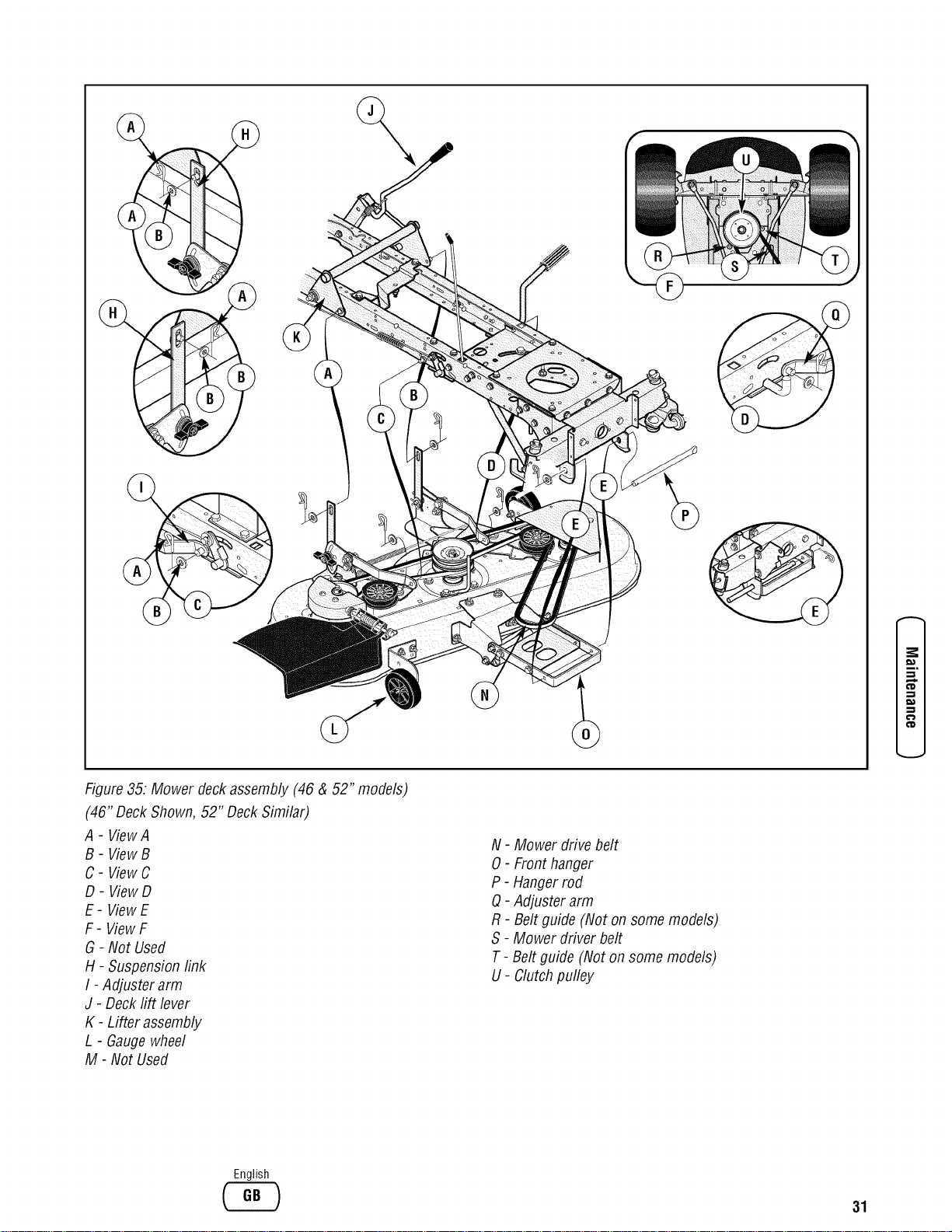
Figure35: Mower deckassembly (46 & 52" models)
(46" DeckShown, 52" DeckSimilar)
A - ViewA
B- ViewB
C- ViewC
D- ViewD
E- ViewE
F- ViewF
G - Not Used
H - Suspension link
I - Adjuster arm
J - Decklift lever
K - Lifter assembly
L - Gaugewheel
M - Not Used
N- Mower drive belt
0 - Front hanger
P - Hangerrod
Q- Adjuster arm
R- Belt guide (Not on some models)
S - Mower driver belt
T- Belt guide (Not on some models)
U- Clutch pulley
(D
English
31
f..._
.E
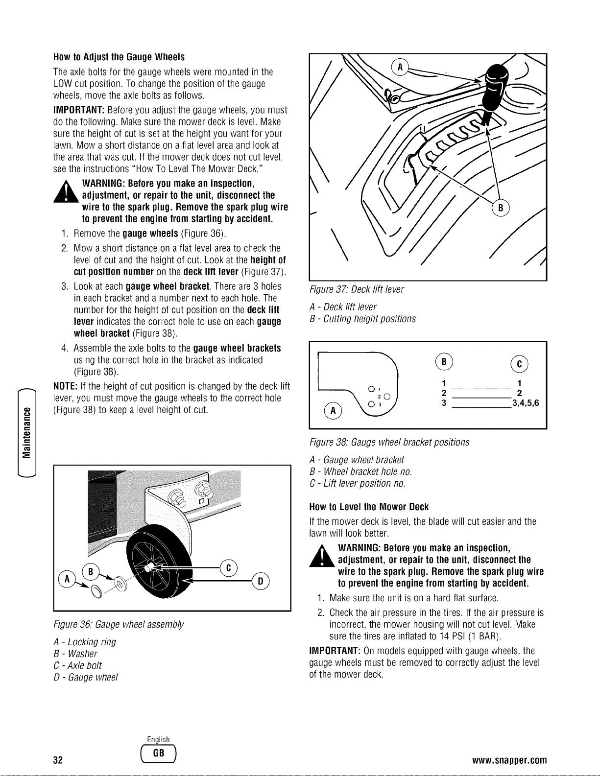
Row to Adjust the GaugeWheels
Theaxle bolts for the gauge wheels were mounted in the
LOWcut position. To changethe position of the gauge
wheels, move the axlebolts as follows.
IMPORTANT:Beforeyou adjust the gaugewheels,you must
do the following. Make surethe mower deck is level. Make
sure the height of cut is set at the heightyou want for your
lawn. Mow a short distance on a flat levelareaand look at
the areathat was cut. If the mower deck does not cut level,
seethe instructions "How To LevelTheMower Deck."
WARNING:Beforeyou make an inspection,
adjustment,or repair to the unit, disconnectthe
wire tothe sparkplug. Removethespark plugwire
to preventthe enginefrom startingbyaccident.
1. Removethe gauge wheels (Figure36).
2. Mow a short distanceon a flat level areato check the
level of cut and the height of cut. Lookat the height of
cutposition numberon the decklift lever (Figure37).
3. Look at eachgauge wheel bracket.Thereare 3 holes
in eachbracket and a number next to eachhole. The
number for the height of cut position on the decklift
lever indicatesthe correct hole to useon eachgauge
wheel bracket(Figure38).
4. Assemblethe axle bolts to the gauge wheel brackets
using the correct hole in the bracket as indicated
(Figure 38).
NOTE:If the height of cut position is changedby the deck lift
lever, you must move the gauge wheels to the correct hole
(Figure38) to keepa levelheight of cut.
©
@
Figure36: Gaugewheelassembly
A - Locking ring
B - Washer
C - Axle bolt
D - Gauge wheel
Figure37: Decktiff lever
A - Deckrift lever
B - Cutting height positions
1
2
3
©
1
2
3,4,5,6
Figure38: Gaugewheelbracketpositions
A - Gaugewheelbracket
B - Wheelbrackethole no.
C- Lift leverposition no.
Howto Level the MowerDeck
If the mower deck is level,the bladewill cut easierandthe
lawn will look better.
WARNING:Beforeyou makean inspection,
adjustment,or repair to the unit, disconnectthe
wire tothe sparkplug. Removethesparkplug wire
to preventthe enginefrom startingbyaccident.
1. Make sure the unit is on a hard flat surface.
2. Checkthe air pressure in the tires. If the air pressure is
incorrect, the mower housing will not cut level. Make
sure the tires are inflated to 14 PSI (1 BAR).
IMPORTANT:Onmodels equipped with gauge wheels,the
gaugewheels must be removed to correctly adjust the level
of the mower deck.
32
English
www.snapper.com
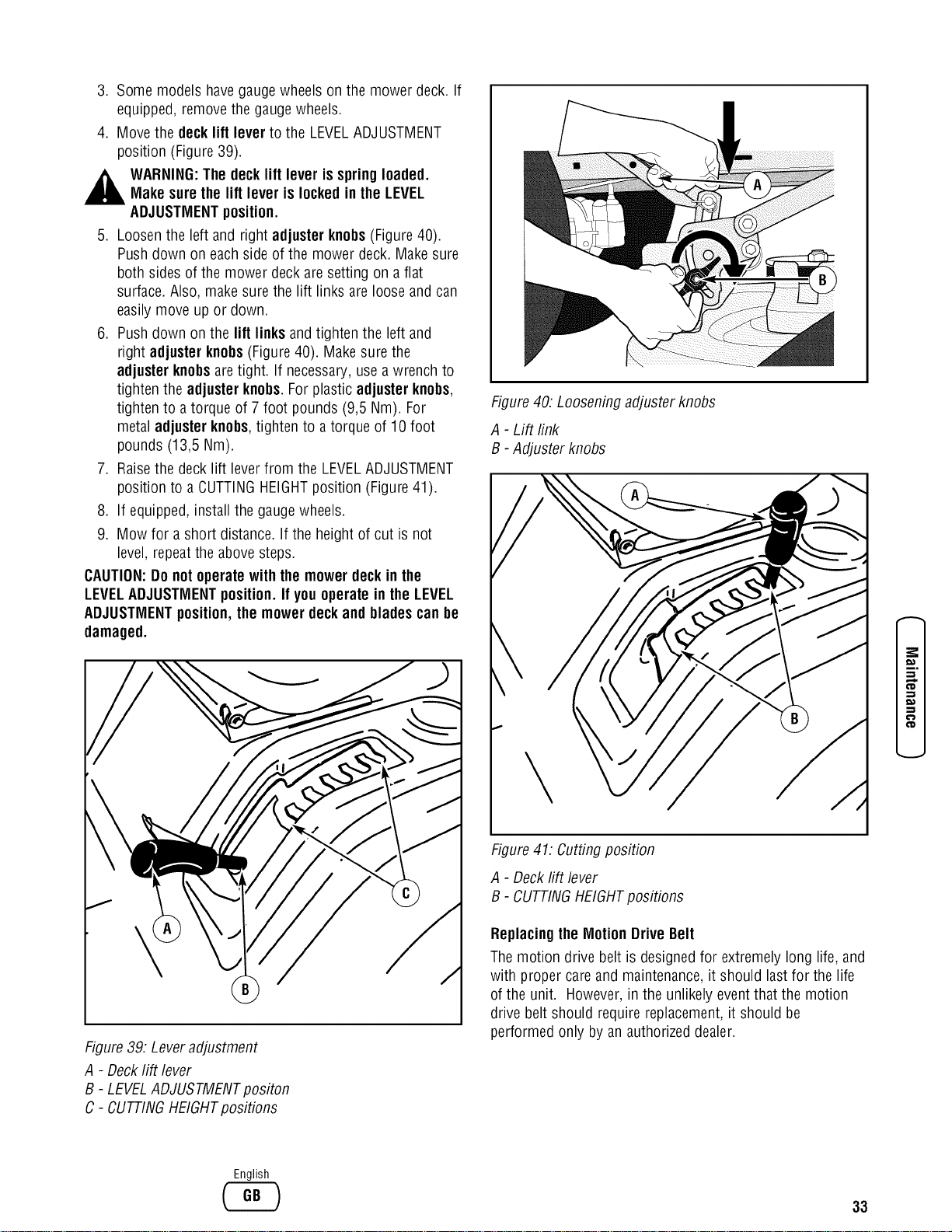
3. Some models havegauge wheels on the mower deck. If
equipped, removethe gauge wheels.
4. Move the decklift lever to the LEVELADJUSTMENT
position (Figure39).
,_ WARNING:The decklift lever isspringloaded.Makesure the lift lever is lockedinthe LEVEL
ADJUSTMENTposition.
5. Loosenthe left and right adjuster knobs(Figure40).
Pushdown on eachside of the mowerdeck. Makesure
both sides of the mower deck are setting on a flat
surface. Also, make surethe lift links are loose and can
easily move up or down.
6. Pushdown on the lift links and tighten the left and
right adjusterknobs(Figure40). Make sure the
adjusterknobsaretight. If necessary,usea wrench to
tighten the adjusterknobs.For plastic adjusterknobs,
tighten to a torque of 7 foot pounds (9,5 Nm). For
metal adjusterknobs,tighten to a torque of 10 foot
pounds (13,5 Nm).
7. Raisethe deck lift leverfrom the LEVELADJUSTMENT
position to a CUTTINGHEIGHTposition (Figure41).
8. If equipped, install the gaugewheels.
9. Mow for a short distance. If the height of cut is not
level, repeatthe abovesteps.
CAUTION:Do notoperatewith the mowerdeckin the
LEVELADJUSTMENTposition.If youoperatein the LEVEL
ADJUSTMENTposition,the mowerdeckand bladescanbe
damaged.
Figure39: Leveradjustment
A - Decklift lever
B - LEVELADJUSTMENTpositon
C - CUTTINGHEIGHTpositions
Figure40: Looseningadjuster knobs
A - Lift rink
B - Adjuster knobs
Figure41: Cutting position
A - Deckrift lever
B - CUTTINGHEIGHTpositions
Replacingthe MotionDriveBelt
Themotion drive belt is designedfor extremely long life, and
with proper care and maintenance,it should last for the life
of the unit. However,in the unlikely eventthat the motion
drive belt should require replacement,it should be
performed only by an authorizeddealer.
,-,z
English
33
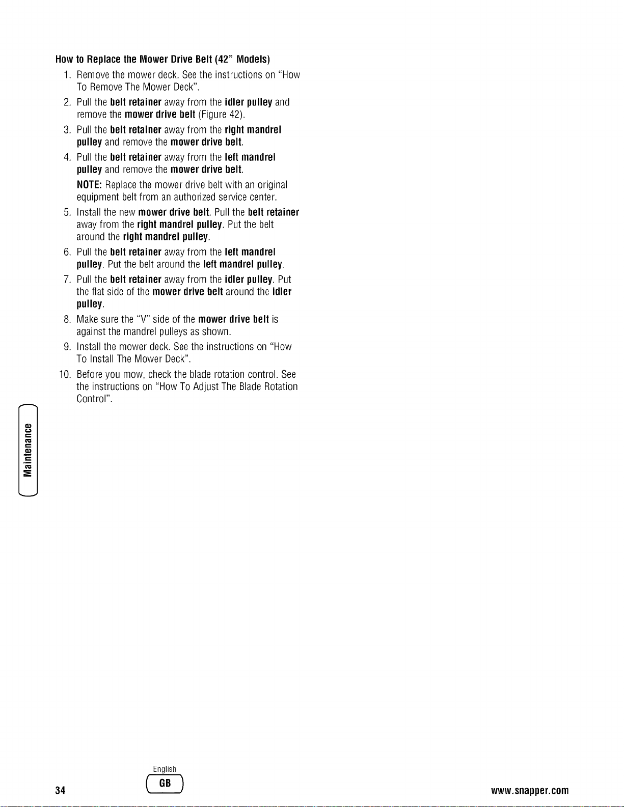
e-
e-
e"
,E
o=
E
Howto Replacethe Mower DriveBelt(42" Models)
1. Removethe mower deck. Seethe instructions on "How
To RemoveThe Mower Deck".
2. Pull the belt retainer awayfrom the idler pulley and
removethe mower drivebelt (Figure 42).
3. Pull the belt retainer awayfrom the right mandrel
pulley and remove the mower drivebelt.
4. Pull the belt retainer awayfrom the leftmandrel
pulley and remove the mower drivebelt.
NOTE:Replacethe mower drive belt with an original
equipment beltfrom an authorized service center.
5. Install the newmower drivebelt. Pull the belt retainer
awayfrom the rightmandrel pulley.Put the belt
around the right mandrel pulley.
6. Pull the belt retainer awayfrom the leftmandrel
pulley. Putthe belt around the left mandrel pulley.
7. Pull the belt retainer awayfrom the idler pulley. Put
the flat side of the mower drivebelt around the idler
pulley.
8. Make sure the "V" side of the mower drivebelt is
against the mandrel pulleys as shown.
9. Install the mower deck.Seethe instructions on "How
To Install The Mower Deck".
10. Beforeyou mow, checkthe blade rotation control. See
the instructions on "How To Adjust The BladeRotation
Control".
34
English
www.snapper.com
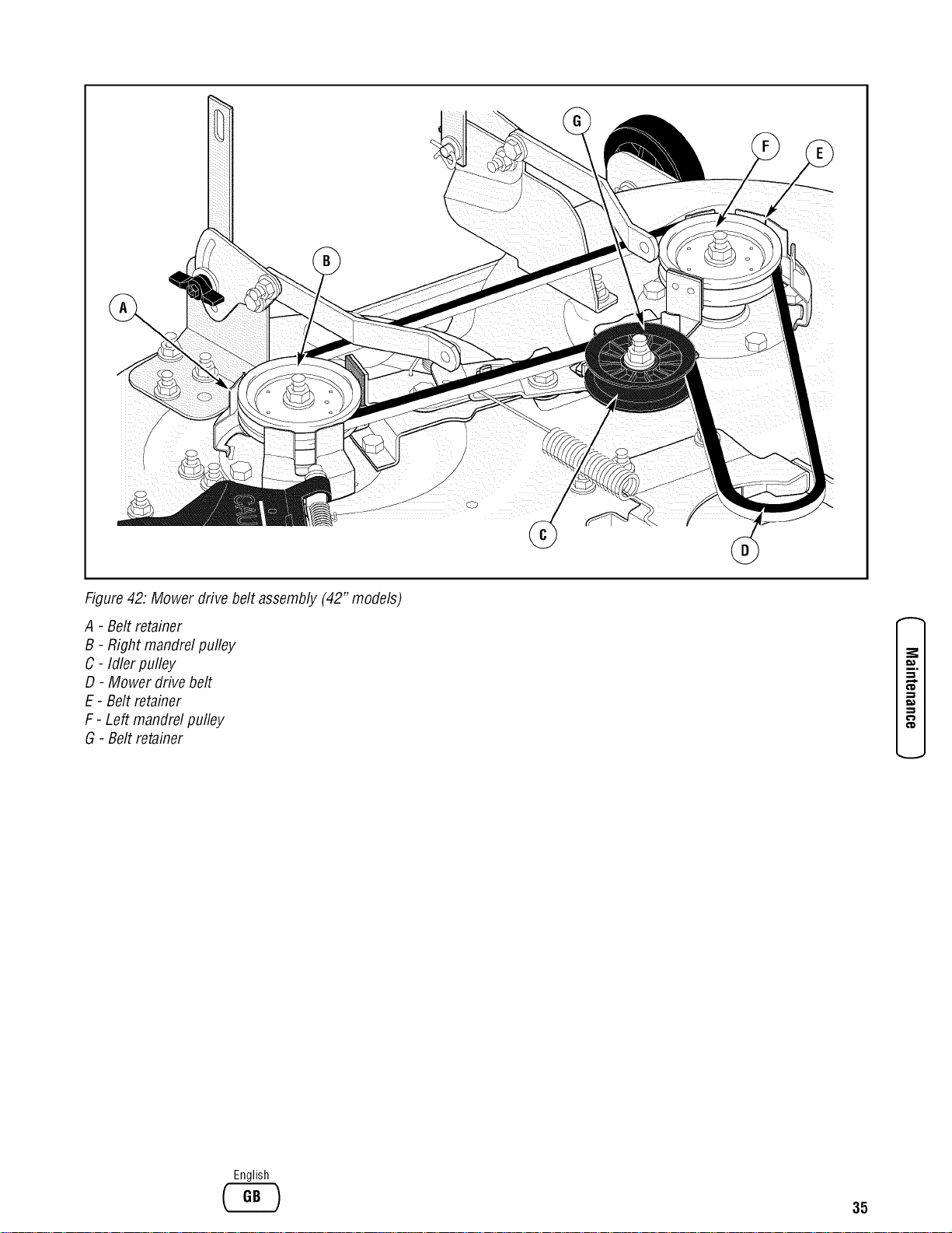
Figure42: Mower drive belt assembly (42" models)
A - Belt retainer
B- Right mandrel pulley
C - Idler pulley
D - Mower drive belt
E - Belt retainer
F - Left mandrel pulley
G - Belt retainer
(D
English
35

e-
e-
e"
,E
o=
Howto Replacethe Primary MowerDrive Belt
(46 & 52" Models)
1. Removethe mower deck. Seethe instructions on "How
To RemoveThe Mower Deck".
2. Removethe threescrews from the left pulley cover.
Removethe pulley cover (Figure43).
3. To remove the primary mower drive belt from the left
mandrel pulley, slidethe primarymower drivebelt
betweenthe left mandrelpulley and the belt guides,
4. Pull the belt retainer awayfrom the idler pulley.
Removethe primarymower drivebelt from the idler
pulley.
5. Removethe primarymower drivebelt from the stack
pulley.
NOTE:Replacethe primary mower drive belt with an
original equipment beltfrom an authorizedservice
center.
6. Install anew primary mowerdrive belt. Putthe belt
around the stackpulley. Makesure the primary mower
drivebelt isinsideof the belt guide.
7. Pull the belt retainer awayfrom the idler pulley. Put
the flat side of the primary mowerdrive belt around
the idler pulley.
8. Make sure the "V" side of the primarymower drive
belt isagainstthe mandrelpulleys asshown.
9. Make sure the primarymower drivebelt is insideall
the belt guides.
10. Assemblethe left pulley cover.
11. Install the mower deck.Seethe instructions on "How
To Install The Mower Deck".
12. Beforeyou mow, checkthe PTOclutch. Seethe
instructions on "How To Adjust The PTOclutch".
Howto Replacethe Secondary MowerDriveBelt
(46 & 52" Models)
1. Removethe mower deck.Seethe instructions on "How
To RemoveTheMower Deck".
2. Removethe primary mower drive belt from the slack
pulley (Figure43).
3. Removethetwo screws from the right pulley cover.
Removethe pulley cover.
4. Pull the idler pulley away from the secondary mower
drive belt. Removethe belt from the idler pulley.
5. Removethe secondary mower drive belt from the right
mandrel pulley.
6. Removethe secondarymower drivebelt from the
stackpulley.
NOTE:Replacethe secondarymower drive belt with an
original equipment belt from an authorizedservice
center.
7. Install a newsecondarymower drivebelt. Putthe belt
around the bottom of the stackpulley. Make surethe
secondarymower drivebelt isinsidethe belt guide
next to the stackpulley.
8. Put the secondarymower drivebelt around the right
mandrel pulley.
9. Pull the idler pulley toward the front. Installthe flat
side of the secondarymowerdrive belt against the
idler pulley.
10. Make surethe "V" side of the secondarymowerdrive
belt is around the right mandrel pulley.
11. Assemblethe right pulleycover.
12. Put the primary mowerdrivebelt around the stack
pulley.
13. Install the mower deck.Seethe instructions on "How
To Install The Mower Deck".
14. Beforeyou mow, checkthe PTOclutch. Seethe
instructions on "How To Adjust The PTOclutch".
36
English
www.snapper.com
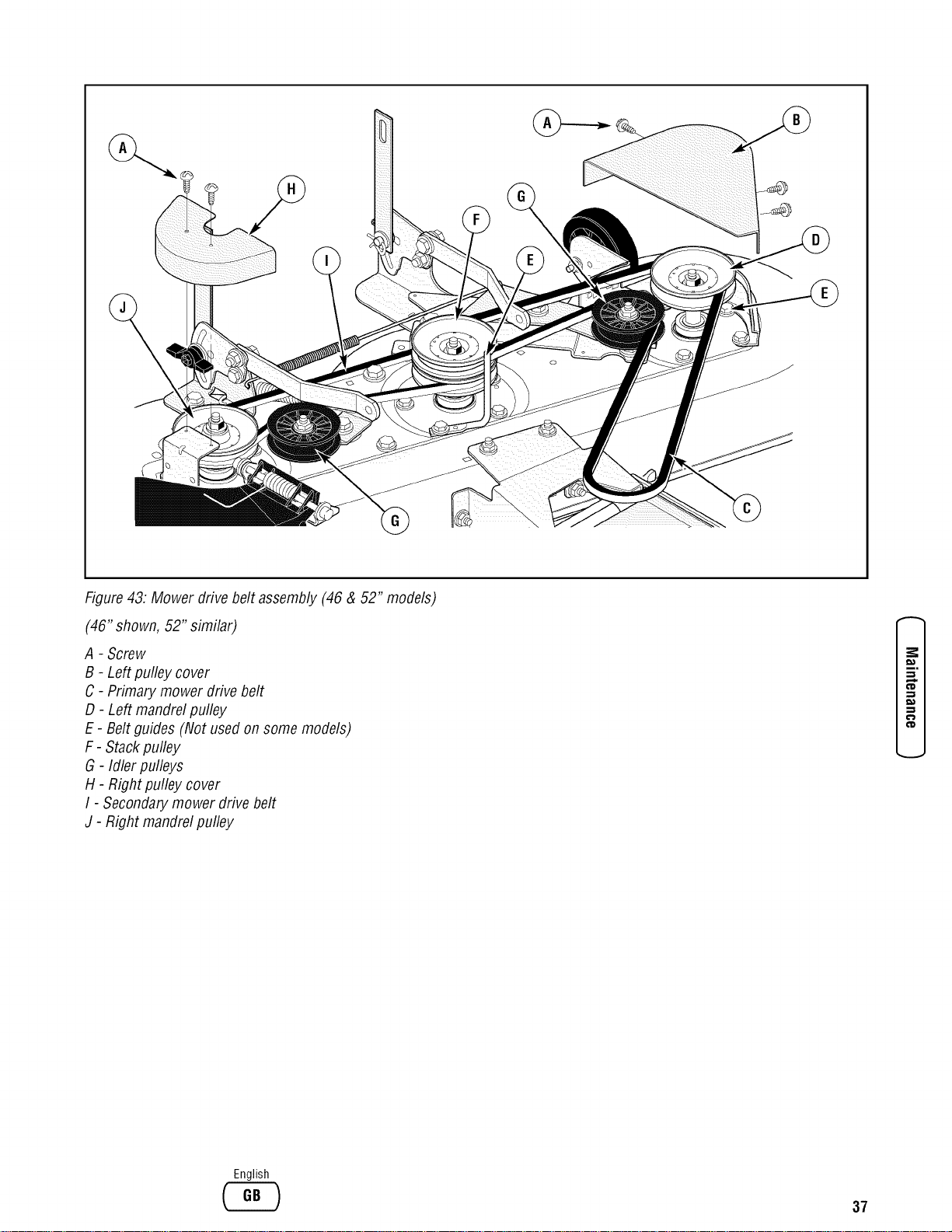
%
Figure43. Mower drive belt assembly (46 & 52" models)
(46" shown, 52" similar)
A - Screw
B - Left pulley cover
C - Primary mower drive belt
D - Left mandrelpulley
E - Belt guides (Not usedon some models)
F - Stackpulley
G - Idler pulleys
H - Right pulley cover
I - Secondarymower drive belt
J - Right mandrel pulley
(D
English
37
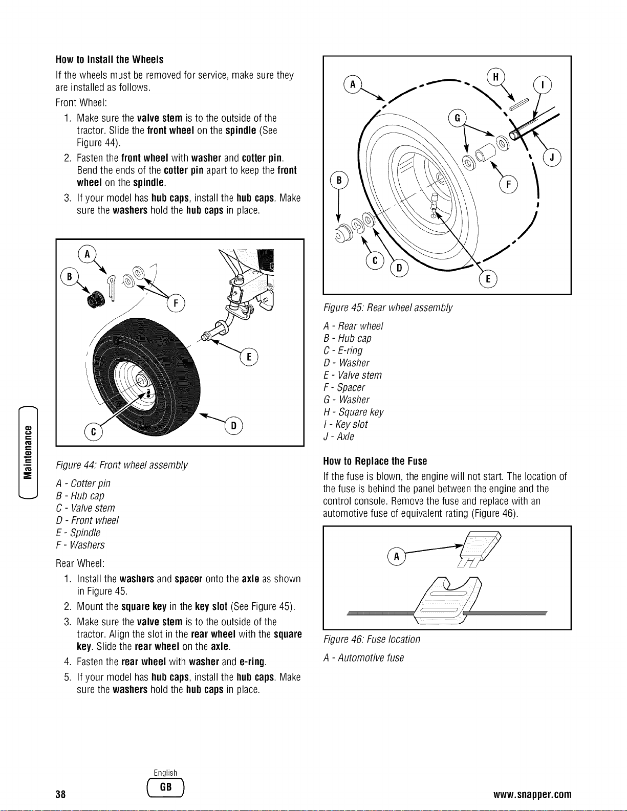
€
,E
How to Install the Wheels
If the wheels must be removedfor service, make sure they
are installed as follows.
Front Wheel:
1. Make sure thevalve stem is to the outside of the
tractor. Slide the frontwheel on the spindle(See
Figure44).
2. Fastenthe frontwheel with washer and cotterpin.
Bendthe endsof the cotterpinapart to keepthefront
wheel on the spindle.
3. If your model has hubcaps, installthe hubcaps. Make
sure the washershold the hubcapsin place.
Figure44. Front wheelassembly
A - Cotterpin
B - Hub cap
C - Valvestem
D - Front wheel
E- Spindle
F- Washers
RearWheel:
1. Install the washers and spacer onto the axle asshown
in Figure45.
2. Mount the square key in the key slot (See Figure45).
3. Make sure thevalve stem is to the outside of the
tractor. Align the slot in the rear wheel with the square
key. Slide the rear wheel on the axle.
4. Fastenthe rear wheel with washerand e-ring.
5. If your model has hubcaps, install the hubcaps. Make
sure the washershold the hubcapsin place.
Figure45: Rearwheelassembly
A - Rearwheel
B - Hubcap
C- E-ring
D- Washer
E - Valvestem
F- Spacer
G- Washer
H- Square key
I - Keyslot
J - Axle
Howto Replacethe Fuse
If the fuse is blown, the engine will not start. The location of
the fuse is behind the panel betweenthe engine and the
control console. Removethe fuse and replacewith an
automotive fuse of equivalent rating (Figure46).
Figure46: Fuselocation
A - Automotive fuse
38
English
www.snapper.com
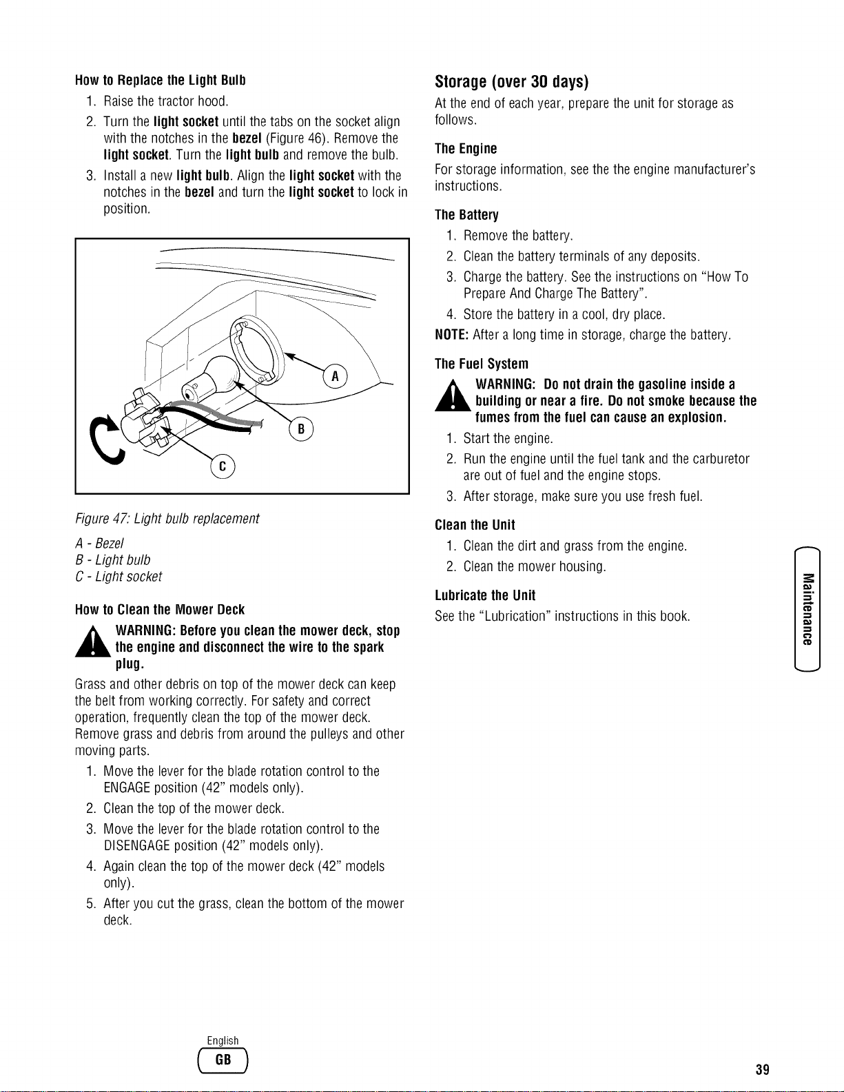
Howto Replacethe Light Bulb
1. Raisethe tractor hood.
2. Turn the light socket until the tabs on the socket align
with the notches in the bezel (Figure46). Removethe
light socket.Turn the light bulband removethe bulb.
3. Install anew light bulb.Align the light socket with the
notches in the bezeland turn the light socket to lock in
position.
Figure47. Light bulb replacement
A - Bezel
B - Light bulb
C - Light socket
Howto Cleanthe MowerDeck
WARNING:Beforeyou clean themower deck, stop
the engineand disconnectthewire tothe spark
plug.
Grassand other debris on top of the mower deck can keep
the belt from working correctly. Forsafety and correct
operation, frequently cleanthetop of the mower deck.
Removegrass and debrisfrom around the pulleys and other
moving parts.
1. Move the leverfor the bladerotation control to the
ENGAGEposition (42" models only).
2. Cleanthe top of the mower deck.
3. Move the leverfor the blade rotation control to the
DISENGAGEposition (42" models only).
4. Again cleanthe top of the mowerdeck (42" models
only).
5. After you cut the grass, cleanthe bottom of the mower
deck.
Storage(over 30 days)
At the end of eachyear, preparethe unit for storage as
follows.
The Engine
Forstorage information, seethe the engine manufacturer's
instructions.
The Battery
1. Removethe battery.
2. Cleanthe batteryterminals of any deposits.
3. Chargethe battery. Seethe instructions on "HowTo
PrepareAnd ChargeThe Battery".
4. Store the battery in a cool, dry place.
NOTE:After a long time in storage, chargethe battery.
The FuelSystem
,_ WARNING: Do notdrain the gasolineinsidea
buildingor near a fire. Donot smokebecausethe
fumesfrom thefuel cancausean explosion.
1. Start the engine.
2. Runthe engine until the fuel tank and the carburetor
are out of fuel and the engine stops.
3. After storage, makesure you usefresh fuel.
Cleanthe Unit
1. Cleanthe dirt and grass from the engine.
2. Cleanthe mower housing.
Lubricatethe Unit
Seethe "Lubrication" instructions inthis book.
,,,..i
¢D
¢D
English
39
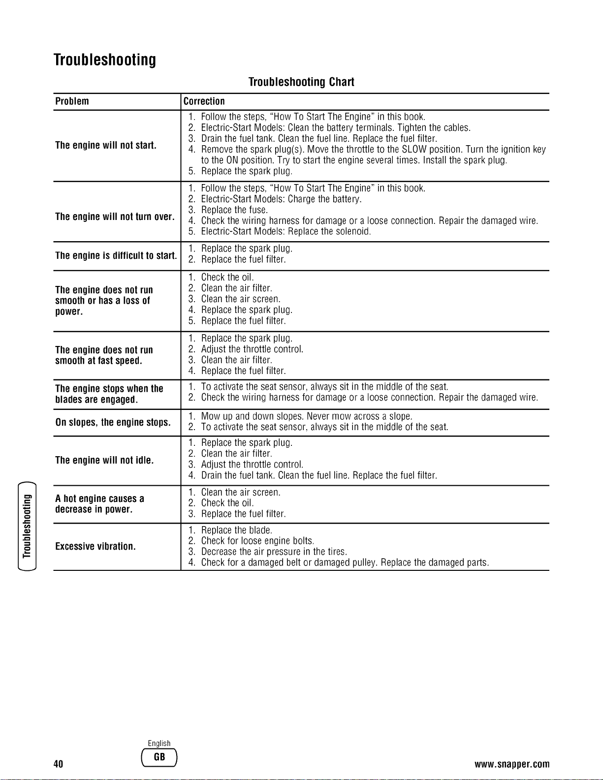
o
o
Troubleshooting
TroubleshootingChart
Problem Correction
The enginewill notstart.
The enginewill notturnover.
1. Follow the steps, "How To Start The Engine" in this book.
2. Electric-Start Models: Cleanthe batteryterminals. Tighten the cables.
3. Drain the fueltank. Cleanthe fuel line. Replacethe fuel filter.
4. Removethe spark plug(s). Move the throttle to the SLOWposition. Turn the ignition key
to the ON position. Try to start the engine severaltimes. Installthe sparkplug.
5. Replacethe spark plug.
1. Follow the steps, "How To Start The Engine" in this book.
2. Electric-Start Models: Chargethe battery.
3. Replacethe fuse.
4. Checkthe wiring harnessfor damageor a looseconnection. Repairthe damagedwire.
5. Electric-Start Models: Replacethe solenoid.
1. Replacethe spark plug.
The engineis difficulttostart. 2. Replacethe fuel filter.
The enginedoesnot run
smoothor hasa lossof
power.
The enginedoesnot run
smoothat fast speed.
The enginestopswhen the
blades are engaged.
Onslopes,the enginestops.
The enginewill not idle.
Ahot enginecausesa
decreasein power.
Excessivevibration.
1. Checkthe oil.
2. Cleanthe air filter.
3. Cleanthe air screen.
4. Replacethe spark plug.
5. Replacethe fuel filter.
1. Replacethe spark plug.
2. Adjust thethrottle control.
3. Cleanthe air filter.
4. Replacethefuel filter.
1. To activatethe seat sensor, always sit in the middle of the seat.
2. Checkthe wiring harnessfor damageor a looseconnection. Repairthe damagedwire.
.
2.
1.
2.
3.
4.
Mow up and down slopes. Nevermow across a slope.
To activatethe seat sensor, always sit in the middle of the seat.
Replacethe spark plug.
Cleanthe air filter.
Adjust the throttle control.
Drain the fueltank. Cleanthe fuel line. Replacethe fuel filter.
1. Cleanthe air screen.
2. Checkthe oil.
3. Replacethefuel filter.
1. Replacethe blade.
2. Checkfor looseengine bolts.
3. Decreasethe air pressure in thetires.
4. Checkfor a damagedbelt or damagedpulley. Replacethe damagedparts.
40
English
www.snapper.com
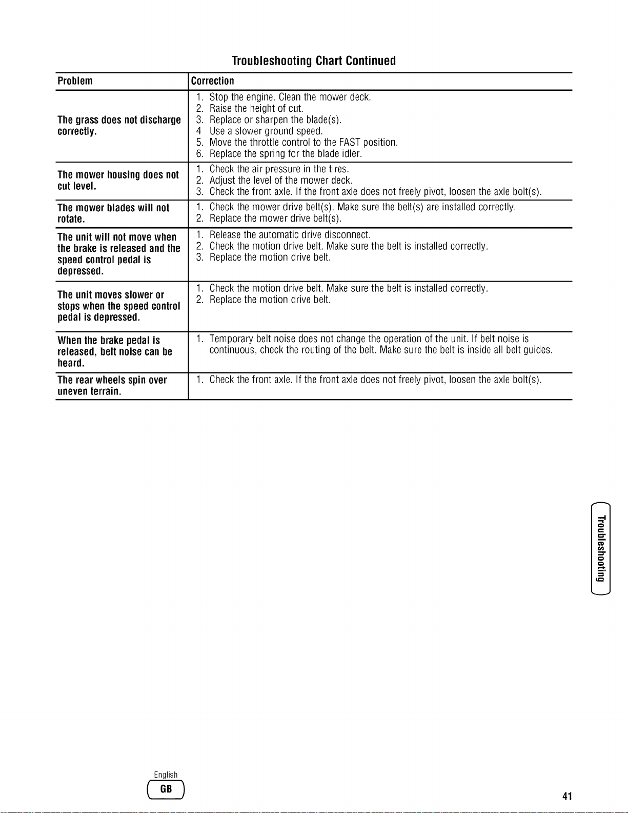
Problem Correction
The grassdoesnotdischarge
correctly.
The mowerhousingdoes not
cutlevel.
The mowerbladeswill not
rotate.
The unitwill notmovewhen
the brake is releasedand the
speedcontrolpedal is
depressed.
The unitmovessloweror
stopswhen thespeed control
pedal isdepressed.
Troubleshooting Chart Continued
1. Stop the engine.Cleanthe mower deck.
2. Raisethe heightof cut.
3. Replaceor sharpenthe blade(s).
4 Use a slower ground speed.
5. Move the throttle control to the FASTposition.
6. Replacethe spring for the bladeidler.
1. Checkthe airpressure in the tires.
2. Adjust the levelof the mower deck.
3. Checkthe front axle. If the front axledoes not freely pivot, loosenthe axle bolt(s).
1. Checkthe mower drive belt(s). Makesure the belt(s) are installed correctly.
2. Replacethe mower drive belt(s).
1. Releasethe automatic drive disconnect.
2. Checkthe motion drive belt. Make surethe belt is installed correctly.
3. Replacethe motion drive belt.
1. Checkthe motion drive belt. Make surethe belt is installed correctly.
2. Replacethe motion drive belt.
Whenthe brake pedal is 1. Temporary belt noise doesnot changethe operation of the unit. If belt noise is
released, belt noisecanbe continuous, checkthe routing of the belt. Make sure the belt is insideall belt guides.
heard.
The rear wheels spinover 1. Checkthe front axle. If the front axledoes not freely pivot, loosenthe axle bolt(s).
uneventerrain.
o
o
o
English
41

Specifications
Product Specifications
LT195420
CLT195420
LT23460
CLT23460
SLT23460
CSLT23460
SLT23460FC
LT24520
CLT24520
SLT24520
CSLT24520
SLT24520FC
Deck Size(inches)
Height of Cut (inches)
Transmission Type
Ground Speed - Fwd/Rev(mph)
Engine Power (hp)
Engine Displacement(cc)
FuelTankCapacity (gal)
42
1.5-4.0
Hydro
0-5.6/0-3.5
19.5
5O8
2.2
46
1.5- 4.0
Hydro
0-5.6/0-3.5
23.0
721
2.2
52
1.5- 4.0
Hydro
0-5.6/0-3.5
24.0
721
2.2
o
,m
t_
,R
t..#
c_
42
English
www.snapper.com
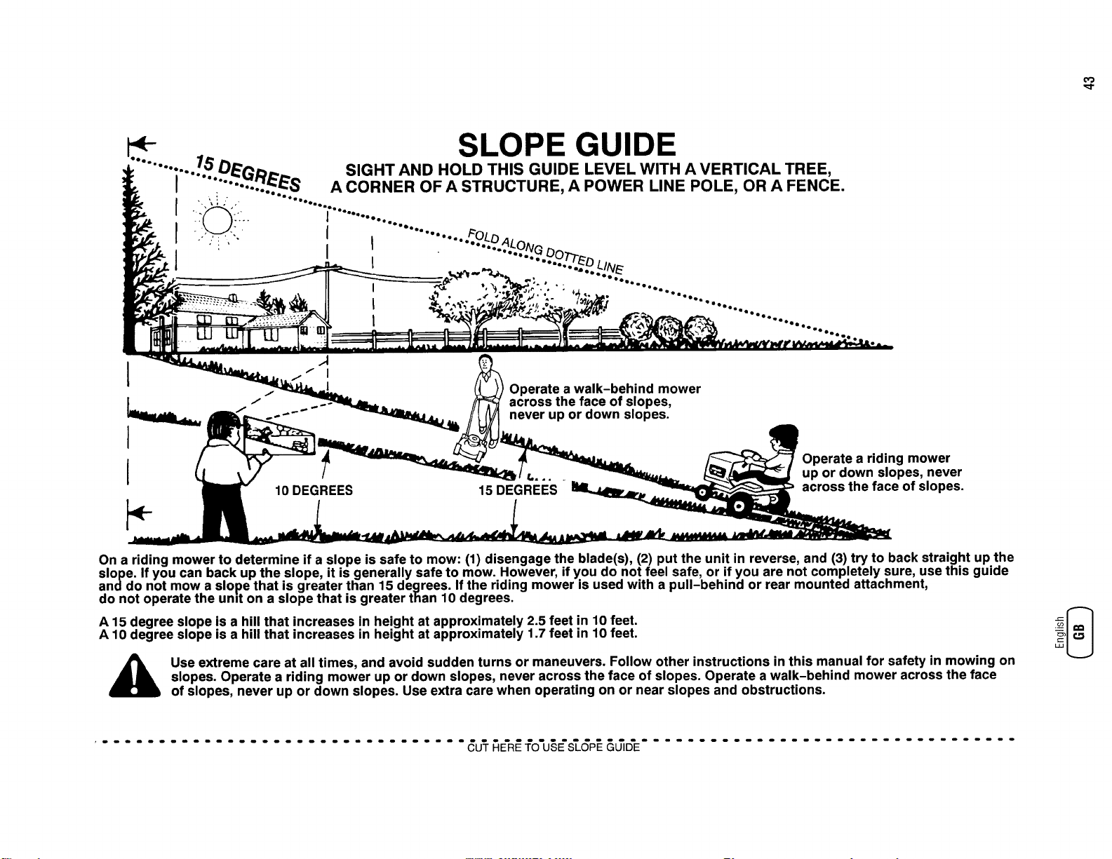
4- SLOPE GUIDE
........ :..../.b" DE_D_... SIGHT AND HOLD THIS GUIDE LEVEL WITH A VERTICAL TREE,
I ".... -'..'.._S A CORNER OF A STRUCTURE, A POWER LINE POLE, OR A FENCE.
j ........................
...... .....................
!
I
I
Operate a walk-behind mower
across the face of slopes,
never up or down slopes.
10 DEGREES 15 DEGREES
Operate a riding mower
up or down slopes, never
across the face of slopes.
On a riding mower to determine if a slope is safe to mow: (1) disengage the blade(s), (2) put the unit in reverse, and (3) try to back straight up the
slope. If you can back up the slope, it is generally safe to mow. However, if you do not feel safe, or if you are not completely sure, use this guide
anddo not mow a slope that is greater than 15 degrees. If the riding mower is used with a pull-behind or rear mounted attachment,
do not operate the und on a slope that is greater than 10 degrees.
A 15 degree slope is a hill that increases in height at approximately 2.5 feet in 10 feet.
A 10 degree slope is a hill that increases in height at approximately 1.7 feet in 10 feet.
Use extreme care at all times, and avoid sudden turns or maneuvers. Follow other instructions in this manual for safety in mowing on
slopes. Operate a riding mower up or down slopes, never across the face of slopes. Operate a walk-behind mower across the face
of slopes, never up or down slopes. Use extra care when operating on or near slopes and obstructions.
=3
................................. _U'T_E'R_fO'U§E'_GP__&_D'E.................................

Notes
44
English
www.snapper.com
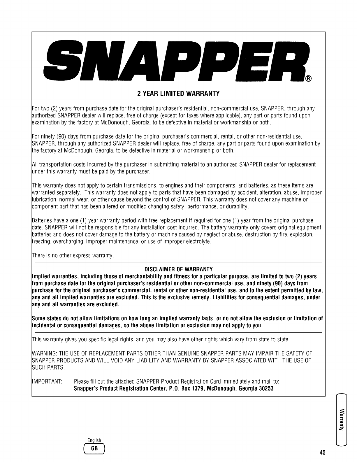
2 YEAR LIMITED WARRANTY
Fortwo (2) years from purchasedatefor the original purchaser's residential,non-commercial use, SNAPPER,through any
authorizedSNAPPERdealerwill replace,free of charge (exceptfor taxes where applicable), any part or parts found upon
_xaminationby the factory at McDonough, Georgia,to be defective in material or workmanship or both.
Forninety (90) days from purchasedatefor the original purchaser's commercial, rental,or other non-residential use,
SNAPPER,through any authorizedSNAPPERdealerwill replace,free of charge, any part or parts found upon examination by
Lhefactory at McDonough,Georgia,to bedefectivein material or workmanship or both.
&ll transportation costs incurred by the purchaser in submitting material to an authorized SNAPPERdealer for replacement
underthis warranty must be paid bythe purchaser.
This warranty does not apply to certain transmissions, to engines and their components, and batteries, asthese items are
_varrantedseparately. This warranty does not apply to parts that have beendamagedby accident, alteration, abuse, improper
lubrication, normal wear, or other cause beyondthe control of SNAPPER.This warranty does not cover any machine or
3omponent part that has beenalteredor modified changing safety,performance, or durability.
Batterieshavea one (1) year warranty period with free replacementif required for one (1) year from the original purchase
date.SNAPPERwill not be responsiblefor anyinstallation cost incurred. Thebattery warranty only covers original equipment
batteriesand does not cover damageto the battery or machine caused by neglect or abuse, destruction by fire, explosion,
freezing,overcharging, improper maintenance,or use of improper electrolyte.
Thereis no other expresswarranty.
DISCLAIMEROFWARRANTY
Implied warranties, includingthoseof merchantabilityand fitnessfor a particularpurpose,are limited to two(2) years
frompurchasedatefor the originalpurchaser'sresidential or othernon-commercialuse, and ninety(90) daysfrom
purchasefor the originalpurchaser'scommercial,rental or othernon-residentialuse, and tothe extentpermittedbylaw,
anyandall impliedwarrantiesare excluded.This isthe exclusiveremedy. Liabilitiesfor consequentialdamages, under
anyandall warranties are excluded.
Somestates donot allow limitations onhow longan implied warrantylasts, or do notallow the exclusionor limitation of
incidentalor consequentialdamages,sothe abovelimitation or exclusionmay notapplyto you.
This warranty gives you specific legal rights, and you mayalso haveother rights which vary from stateto state.
WARNING:THEUSEOFREPLACEMENTPARTSOTHERTHANGENUINESNAPPERPARTSMAY IMPAIRTHE SAFETYOF
SNAPPERPRODUCTSAND WILL VOIDANY LIABILITYANDWARRANTYBYSNAPPERASSOCIATEDWITH THE USEOF
SUCHPARTS.
IMPORTANT:
Pleasefill out the attachedSNAPPERProduct Registration Cardimmediately and mail to:
Snapper's ProductRegistrationCenter, P.O. Box1379, McDonough,Georgia30253
English
45

LAWNTRACTOR
SERIES0
EnginePower RatingInformation:The gross power rating for individual gasengine models is labeled in accordancewith
SAE(Societyof Automotive Engineers)codeJ1940 (Small Engine Power& Torque Rating Procedure),and rating
performancehas been obtainedand corrected in accordancewith SAEJ1995 (Revision 2002-05). Torque valuesare derived
at3060 RPM;horsepower values are derived at 3600 RPM.Actual gross engine power will be lower and is affectedby,
amongother things, ambient operating conditions and engine-to-enginevariability. Givenboth the wide arrayof products on
which engines are placedand the variety of environmental issuesapplicableto operating the equipment,the gasengine will
not developthe ratedgross power when used in a given pieceof power equipment(actual"on-site"or net power). This
differenceis due to a variety of factors including, but not limited to, accessories(air cleaner, exhaust, charging, cooling,
carburetor, fuel pump, etc.), application limitations, ambient operating conditions (temperature, humidity, altitude), and
engine-to-enginevariability. Dueto manufacturing and capacity limitations, Briggs & Stratton may substitute an engine of
higher ratedpower for this Seriesengine.
_J_LDJ_EJ_ SnapperProducts
535 MlaconStreet
IVlcDonough,GA30253
1-800-317-7833

