Loading ...
Loading ...
Loading ...
SYSTEM CONFIGURATION
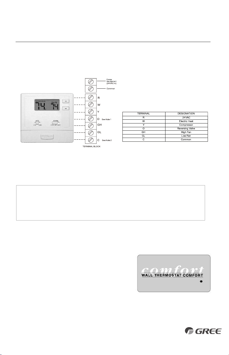
Fig. 23 – Wall Thermostat
Control Panel Label
(Part# 62261101)
NOTE: For thermostats that have only one fan speed output (on or auto), the fan speed
is determined by how the terminal connector is wired. If Low fan is desired, wire the
G output from the thermostat to GL on the unit’s terminal block. If Hi fan is desired, wire
the G output from the thermostat to GH on the unit’s terminal block.
WALL THERMOSTAT INSTALLATION (CON’T)
7. Connect thermostat wire to the ETAC II thermostat connection terminals per wire diagram (see
Fig.
22).
8. Carefully re-attach thermostat terminal block on unit.
9. Locate configuration dip switches above thermostat
terminal connections. Set switch #2 "UP" for Wall
Thermostat Mode (see Fig. 17).
10.
Install thermostat escutcheon label over touchpad
control panel (see Fig. 23). Included in I/O packet.
11.
Mount, wire and configure wall thermostat
per instructions provided by the manufacturer.
12.
Restore power to unit and verify wall thermostat operation.
NOTES:
1. Use terminal “O” for heat pump connection only.
2. Terminal “C” (common) is typically only required
for digital thermostats.
NOTES:
Any illegal input combinations will be captured as thermostat
wiring failures and will light the STATUS LED indicator on main
board (see Intelligent Self-Checking Control section).
Fig. 22 – Wiring Connections
1918
Loading ...
Loading ...
Loading ...