Loading ...
Loading ...
Loading ...
Maintenance
Owner’s Manual for 60 Hz Air-Cooled Generators 29
3. Remove spark plug(s) and inspect. Install new
plug(s) if existing plug(s) is worn or if reuse is ques
-
tionable.
4. Clean plug(s) by scraping or washing with a wire
brush and commercial solvent. Do not blast plug(s)
to clean.
NOTE: Clean spark plug in emergency situations only.
Otherwise, replace spark plug.
5. See Figure 4-6. Inspect spark plug gap using a
wire feeler gauge. Replace spark plug if gap is out
of specification. See
General Information.
Figure 4-6. Spark Plug Gap Measurement
NOTE: New spark plugs should have spark plug gap
checked prior to installation.
6. Install spark plug(s), and tighten to 18.4 ft-lbs (25
Nm).
7. Press AUTO button to return unit to AUTO mode.
Valve Clearance Adjustment
IMPORTANT NOTE: Contact an IASD for service
assistance. Correct valve clearance is essential for
prolonging the life of the engine. Excludes units
equipped with hydraulic lifters. See Engine.
Inspect valve clearance after first 25 hours of operation,
then after 400 hour intervals. Adjust if necessary.
Checking Valve Clearance
NOTE: Engine should be cool before checking valve
clearance. Adjustment is not needed if valve clearance is
within dimensions provided in Engine.
Proceed as follows to check valve clearance.
1. Close fuel valve and disconnect battery to avoid
accidental startup.
2. Remove spark plug wire(s), and position wire(s)
away from plug(s).
3. Remove spark plug(s).
4. Remove the four screws attaching the valve cover.
Remove and discard gasket. (Repeat for second
cylinder, if equipped.)
5. Verify piston is at top dead center (TDC) of its com-
pression stroke (both valves closed). To move pis-
ton to TDC, remove intake baffle at the front of the
engine to access the flywheel nut. Use a large
socket and socket wrench to rotate flywheel nut
clockwise, which will rotate the crankshaft. Watch
piston through spark plug hole. Piston will move up
and down. Piston is at TDC when at its highest
point of travel.
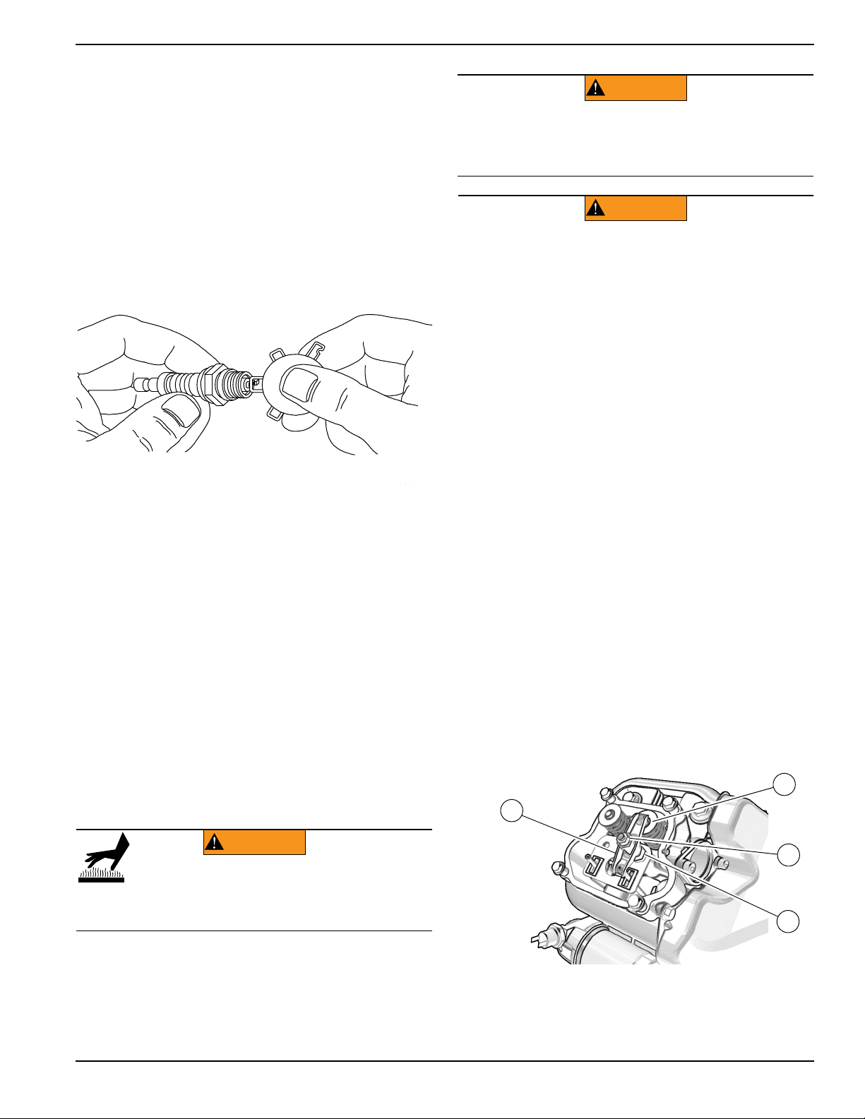
6. See Figure 4-7 or Figure 4-8. Inspect valve clear-
ance between each rocker arm (E) and valve stem
(F) with a feeler gauge.
.
Figure 4-7. Valve Clearance Adjustment (10 kW)
000211
000211
WARNING
Risk of Burn. Allow the engine to cool before
performing the following procedure. Failure to
do so could result in serious injury.
(000560)
(000130)
WARNING
Accidental Start-up. Disconnect the negative battery
cable, then the positive battery cable when working
on unit. Failure to do so could result in death
or serious injury.
(000141)
WARNING
Accidental start-up. Disconnect spark plug wires when
working on unit. Failure to do so could result in death
or serious injury.
001812
C
D
F
E
Loading ...
Loading ...
Loading ...