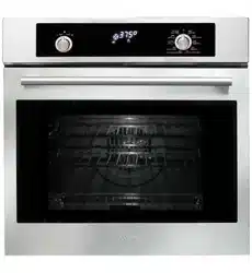
INSTRUCTION MANUAL
FOR 60 SERIES BUILT-IN
OVEN 600SPYKT
GB
1
SAFETY INSTRUCTIONS 2
INSTALLATION OF THE OVEN 4
Electricals 4
Respect for the environment 5
Connection to the electrical power
mains
7
INSTRUCTIONS FOR USE 8
The first time you use the oven 8
Oven Racks 8
Removable Guides 8
COOKING FUNCTIONS 9
ELECTRONIC CONTROL 11
Power-up 11
Programming time functions 11
Setting the time of day 11
Setting the minute minder 12
Setting an oven function manually 13
Setting an automatic oven function 13
Oven functions 14
Eco-Bake 15
Defrost 15
Pyrolyse (Self-Clean) 15
Door lock for children safety (pyro) 16
Commands lock for children safety
(non pyro)
16
Buzzer volume 16
Failure declarations and error codes 16
DOOR LOCKING SYSTEM
18
CLEANING AND MAINTENANCE 19
Self-cleaning cycle (pyrolytic
cycles)
19
Removing the “FULL GLASS”
panoramic door
20
How to remove the inner glass of
the “FULL GLASS” panoramic door
21
Replacement of the oven light 23
GUIDANCE TEMPERATURE AN
TIME SCHEDULE FOR COOKING
24
TABLE OF CONTENTS
IMPORTANT
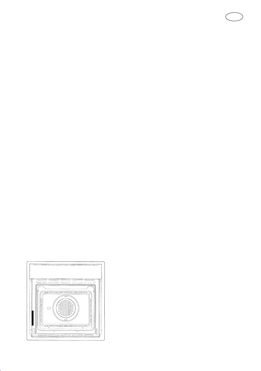
The oven’s data plate is accessible even with the oven
fully installed. The plate is visible simply by opening
the door. Always quote the details from it to identify
the appliance when ordering spare parts.

GB
2
SAFETY INSTRUCTIONS
- Do not disassemble any parts prior to having disconnected the oven from the
mains.
- Do not use the appliance if any part is broken (for example a glass). Disconnect it
from the mains and call service.
- Before using the oven, it is recommended to make it operate at noload at the maximum
temperature for an hour to eliminate the insulating material odour.
- In all models, leave the door closed when the grill is used.
- The cooling fan may remain in operation so long as the oven is hot, even after it has
been switched off.
- During the use the appliance becomes very hot; don’t touch the heating elements
inside the oven.
- During the oven operation, the front is heated as well; consequently keep children
clear of the oven, especially during self-cleaning.
- Parents and adults should pay particular attention when using the product in presence
of children.
- Children should be overseen so as to ensure that they don’t play with the equipment.
- Keep children under age 8 away, unless constantly supervised.
- This appliance is not intended for use by persons (including children over age 8) with
reduced physical sensory or mental capabilities, or lack of experience and knowledge,
unless they have been given supervision or instruction concerning use of the appliance
by a person responsable for their safety.
- Children may not perform cleaning and maintenance unsupervised.
- In order to avoid damage to the oven enamel coat, do not cover the oven muffle sole
with any item (e.g. aluminum foil, pans and the likes).
- Do not use harsh abrasive cleaners or sharp metal scrapers to clean the oven door
glass since they can scratch the surface, which may result in shattering of the glass.
- Abrasive detergents and steam cleaning equipment should not be used for cleaning.
- Before performing self-cleaning, take out all accessories (grills, dishes, pans) to avoid
damaging them, remove large cooking residues and then close the door, ensuring that
it is closed properly.
- The oven is cool and power to the oven has been turned off before removing the door.
Failure to do so could result in electrical shock or burns.
- The appliance must not be installed behind a decorative door in order to avoid
overheating.
- WARNING: Ensure that the appliance is switched off before replacing the lamp to
avoid the possibility of electric shock.
GB
3
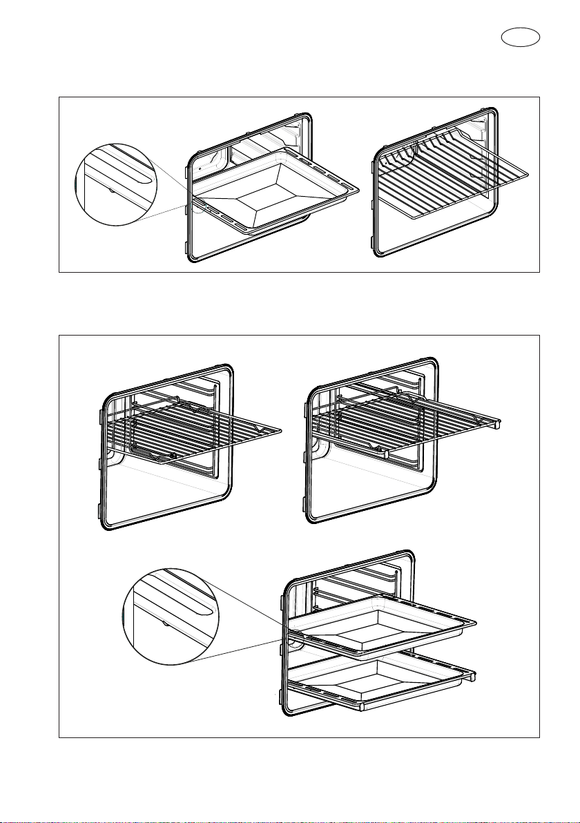
Refer to the figures below for the correct placement of the grills
EMBOSSED GUIDES
REMOVABLE GUIDES

GB
4
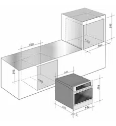
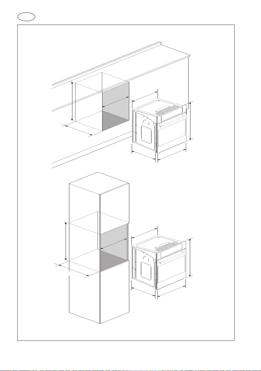
INSTALLATION OF THE OVEN
To install the oven into the kitchen a cutout should be made in accordance with the
dimensions shown in figure.
The apparatus is to be fastened to the top by means of the two screws provided in the
kit through the holes made on the oven uprights.
The cabinet in which the apparatus is installed shall be open on the back side to ensure
a sufficient air circulation and prevent overheating.
Leave a gap of at least 200 cm2 (see Fig. 1) for air circulation if the oven is installed in a
column; this is not necessary if the oven is installed under the work top.
WARNING
As the apparatus is to be fitted in your kitchen furniture, make
sure that all surfaces in contact with the oven can resist a
temperature of approx 90°C.
Electricals
- Absorbed power:
oven top element:........................................... 1200+1000W 230V - 1200+1000W 240V
oven bottom element: .................................... 1100W 230V - 1100W 240V
round element (hot air): .................................. 2300W 230V - 2300W 240V
(on some models)
roasting jack motor: ....................................... 4 W (on some models)
lamp: .............................................................. 25 W
hot air fan motor:............................................ 25 W
cooling fan motor:........................................... 25 W
- Maximum absorbed power: (see data plate).
- Supply voltage: (see data plate).
NOTE
This appliance is in compliance with following European directives:
2006/95/CE (LVD), 2004/108/CE (EMC), 2011/65/CE (RoHS),
2012/19/UE (WEEE), 2002/40/CE.
GB
5
Respect for the environment
The documentation for this appliance is printed on paper bleached without
chlorine or recycled paper to contribute to protecting the environment.
The packaging was designed to prevent damage to the environment; they
are ecological products that can be recovered or recycled.
Recycling the packing saves raw materials and reduces the volume of
industrial and domestic waste.
THE PACKING MATERIAL is 100% recyclable and marked with the recycling symbol.
Dispose of in conformity with local law. The packing material (plastic bags, polystyrene
parts, etc.) must be kept out of the reach of children because it is potentially dangerous.
THIS APPLIANCE is marked in conformity with European Directive 2012/96/UE, Waste
Electrical and Electronic Equipment (WEEE). By making sure that this product is disposed
of correctly, the user contributes to preventing potential negative consequences for the
environment and health.
THE SYMBOL on the product or accompanying documentation indicates
that this product must not be treated as domestic waste but must be
delivered to a suitable collection point for the recycling of electrical and
electronic equipment.
GB
6
535
21
594
594
540
560
560
595
535
21
594
594
540
560
595
560
Dimensions are in millimeters
GB
7
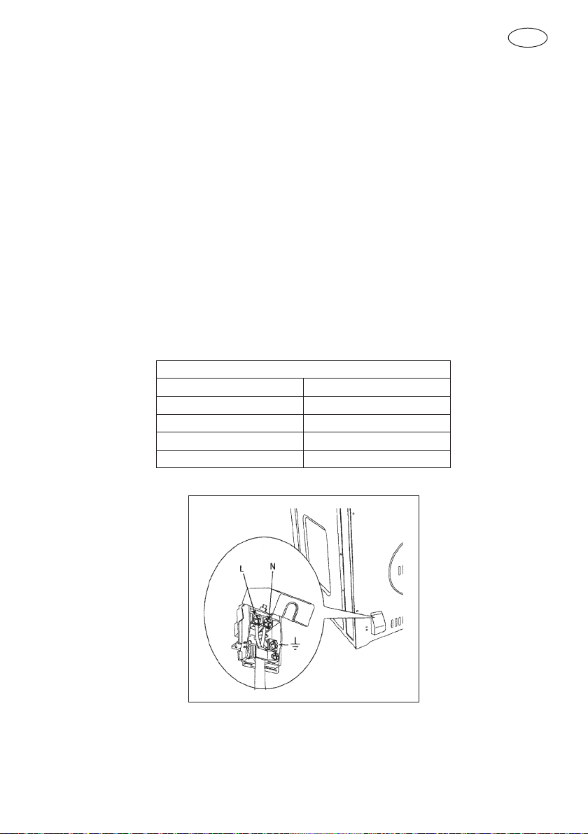
Connection to the electrical power mains
WARNING
This apparatus must be earthed.
The oven is only for domestic use.
The feed voltage and the absorbed power are as indicated on the data plate attached to
the left-hand side upright, which can be seen when the oven door is open.
Connecting must be carried out by qualified personnel and in accordance with the
regulations currently in force.
The manufacturer can not be held responsible for any damages to persons or objects
caused by failure to observe these instructions.
If the supply cord is damaged, it must be replaced by the manufacturer, its service agent
or similarly qualified persons in order to avoid a hazard.
The oven must be connected to the mains through a multipole circuit breaker with
a contact-to-contact gap of at least 3 mm, making sure that the earth wire is not
disconnected. For connecting use a flexible cable remembering to make it long enough
to allow the oven to be removed from its housing unit when maintenance work is
required.
CABLE TYPES AND MINIMAL DIAMETERS
SASO
H05RR-F 3x1,5 mm
2
H05RR-F 3x2,5 mm
2
H05VV-F 3x1,5 mm
2
H05VV-F 3x2,5 mm
2
H05RN-F 3x1,5 mm
2
H05RN-F 3x2,5 mm
2
H05V2V2-F 3x1,5 mm
2
H05V2V2-F 3x2,5 mm
2
GB
8
INSTRUCTIONS FOR USE
The first time you use the oven
Clean the oven thoroughly with soapy water and rinse well. Operate the oven for about
30 minutes at maximum temperature to burn off all traces of grease which might
otherwise create unpleasant smells when cooking.
Oven Racks
WARNING
Never use aluminum foil to cover the oven racks or to line the
oven. It can cause damage to the oven liner if heat is trapped
under the foil.
WARNING
Make sure you do not force it to avoid damage to the enamel.
The oven has rack guides at four levels. Rack positions are numbered from the bottom
rack guide (#1) to the top (#4).
Check cooking charts for best rack positions to use when cooking.
Always be sure to position the oven racks before turning on the oven. Make sure that the
racks are level once they are in position.
The racks are designed to stop when pulled forward to their limit.
Removable Guides
NOTE
Always remove the removable guides before oven self-
cleaning.
To remove the lateral frames from smooth-walled ovens, proceed as shown in the figure.
GB
9
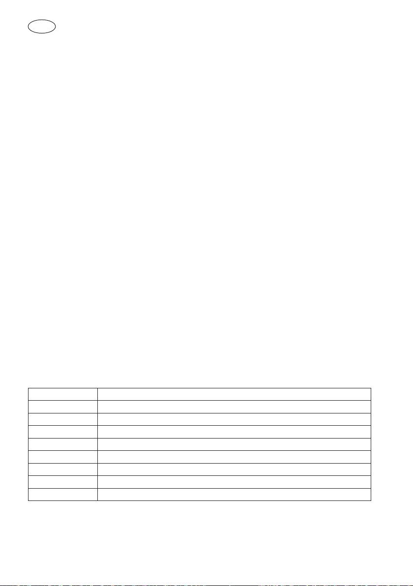
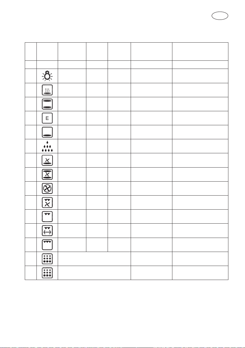
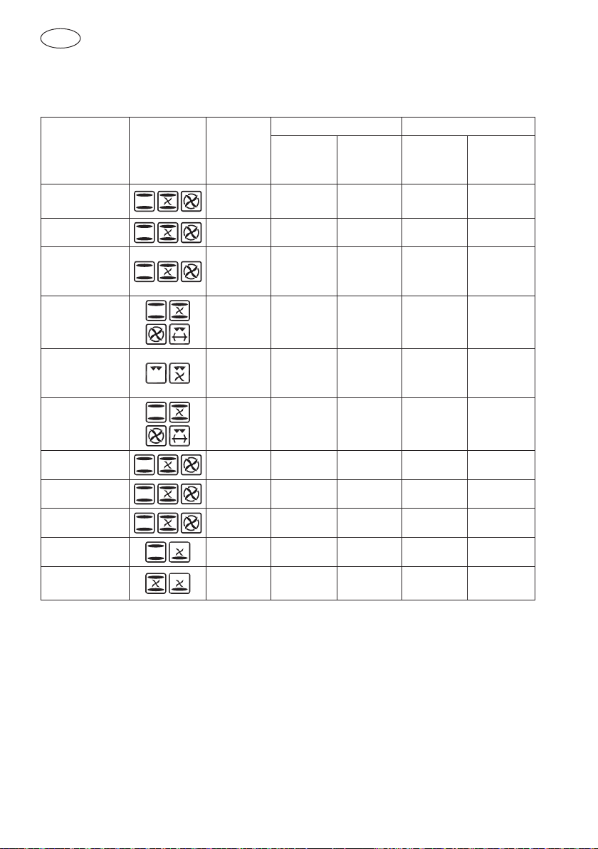
COOKING FUNCTIONS
Each type of oven is provided for various cooking systems. A system can be selected
by bringing the pointer of knob to the relating symbol. The Fig. 8 shows the controls
available on the different oven models.
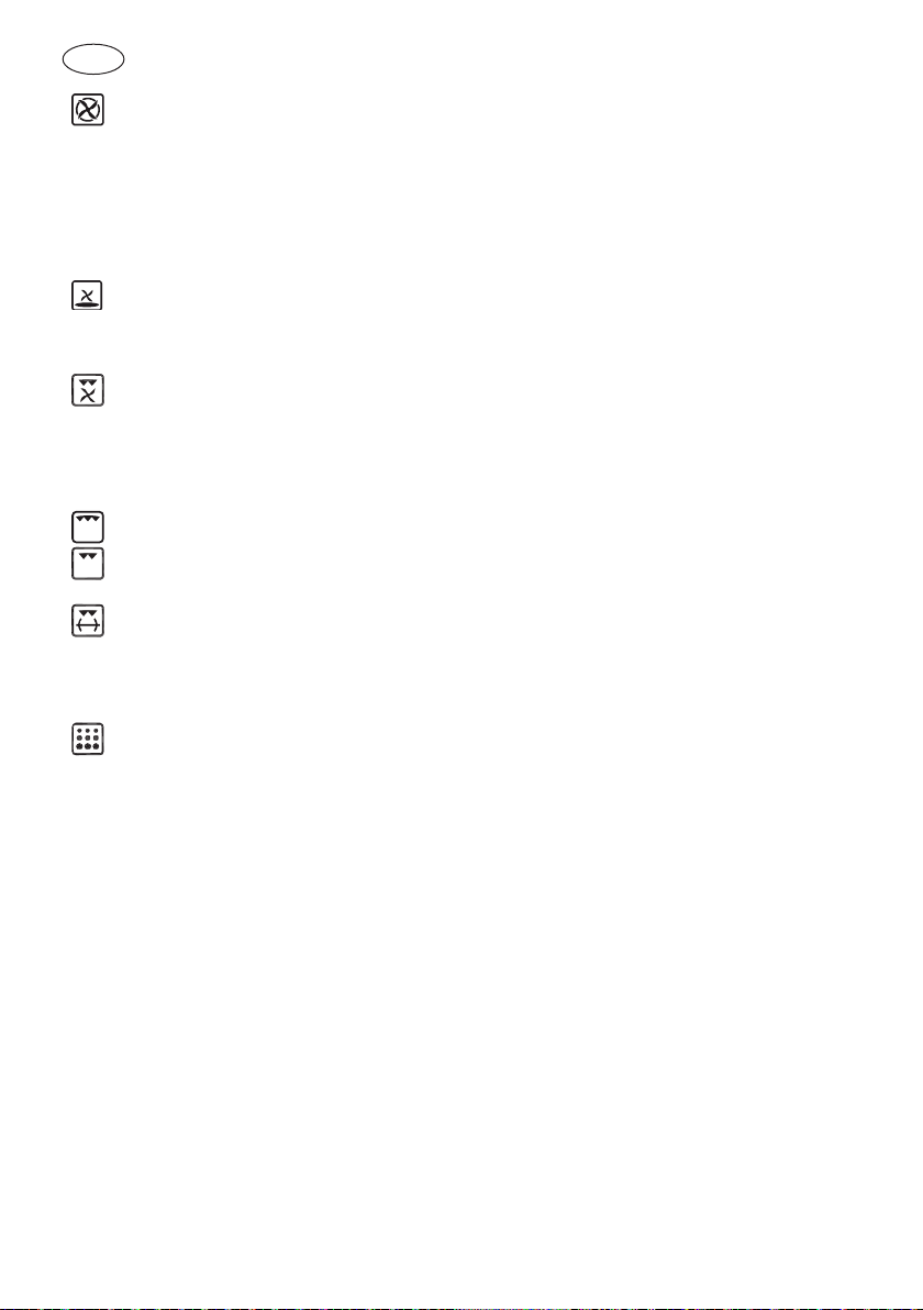
Icon Mode Description Used for…
0 All the cooking modes are OFF and
the oven heating elements are OFF.
---
The light is on only. ---
In this mode only the internal oven
convection fan is ON i.e. there is no
oven heating
This mode is used to defrost
deepfrozen food.
In this mode only the smaller bottom
heating element is on.
This mode is used to keep foods
warm.
In this mode both upper (top)
and lower (bottom) oven heating
elements are used to heat the oven
air. However, no fan is used to
circulate the heat.
This is the traditional mode of
cooking on one shelf. Therefore only
one rack can be used when selecting
the Bake mode. Ideal for Appetizers,
Biscuits, Coffee Cakes and Cookies.
This mode is intended to save energy.
In particular the oven cooling fan
works only when needed e.g. when
the oven is hot and the electronics
require cooling.
Ideal for frozen or precooked food,
and small portions-mealsThe preheat
time is very short and cooking tends
to be slower.It is not recommended
for heavy loads e.g. large portions or
big meal preparation.
Only the lower (bottom) oven heating
element is activated.
Used to complete cooking.
The Convection Roast mode uses
the upper (top) oven heating element,
the lower (bottom) heating element
and the convection fan inside the
oven.
Ideal for the roasting of whole
chickens or turkey and pizza.It can
also be used for baking-cooking
Appetizers, Biscuits, Coffee Cakes
and Cookies on one or more levels.
GB
10
The Convection Bake mode uses
the circular or third heating element
hidden behind the baffle at the
back wall of the oven. The heat is
circulated throughout the oven by
the convection fan.
Consequently different foods can be
cooked simultaneously (maximum
three levels) and is suitable for
preparing a complete dinner (small
portions). Mixing of flavours is
avoided and an important energy
saving is obtained.
The Convection Down mode uses
the lower (Bottom) heating element
and internal fan.
Useful for soufflés, pizzas and pastry
dishes.
suitable for preparing a complete
dinner (small portions). Mixing of
flavours is avoided and an important
energy saving is obtained.
Ideal for steak, hamburgers, chicken
quarters or chicken breasts.
The Grill mode uses intense heat
radiated from the upper (top) heating
element.
Ideal for preparing toast, browning
and grilling.
If the spit device is fitted it is also
used with the spit motor.
If the spit motor is fitted the spit
roasting of a whole chicken or turkey
is possible.
The standard time is 1.30 h and can
be changed. (see page 16)
PYRO or self-cleaning mode. Here
the oven is automatically cleaned by
burning-off cooking residues at high
temperature (about 475 °C) from 1h
to 3h. During the self-cleaning cycle
all fumes produced are filtered and
then expelled to ambient.
GB
11
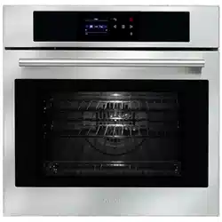
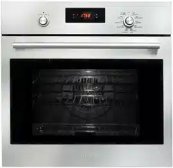
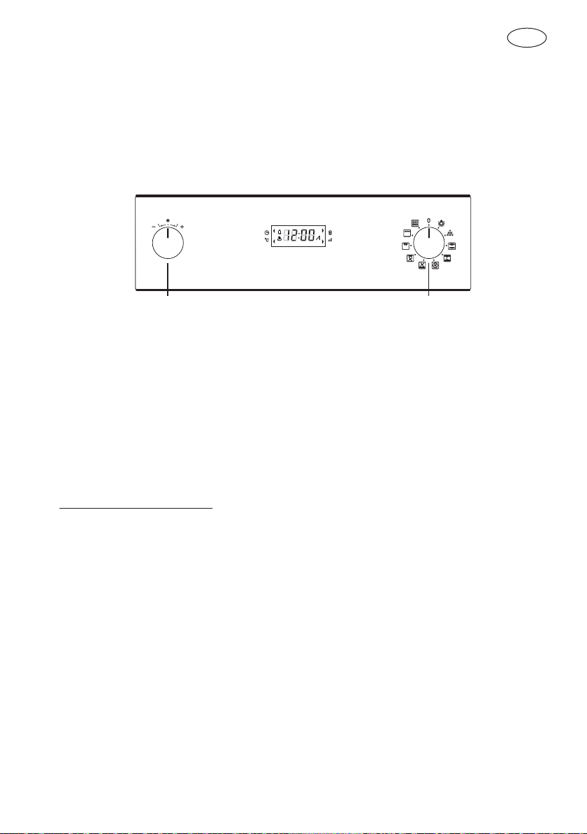
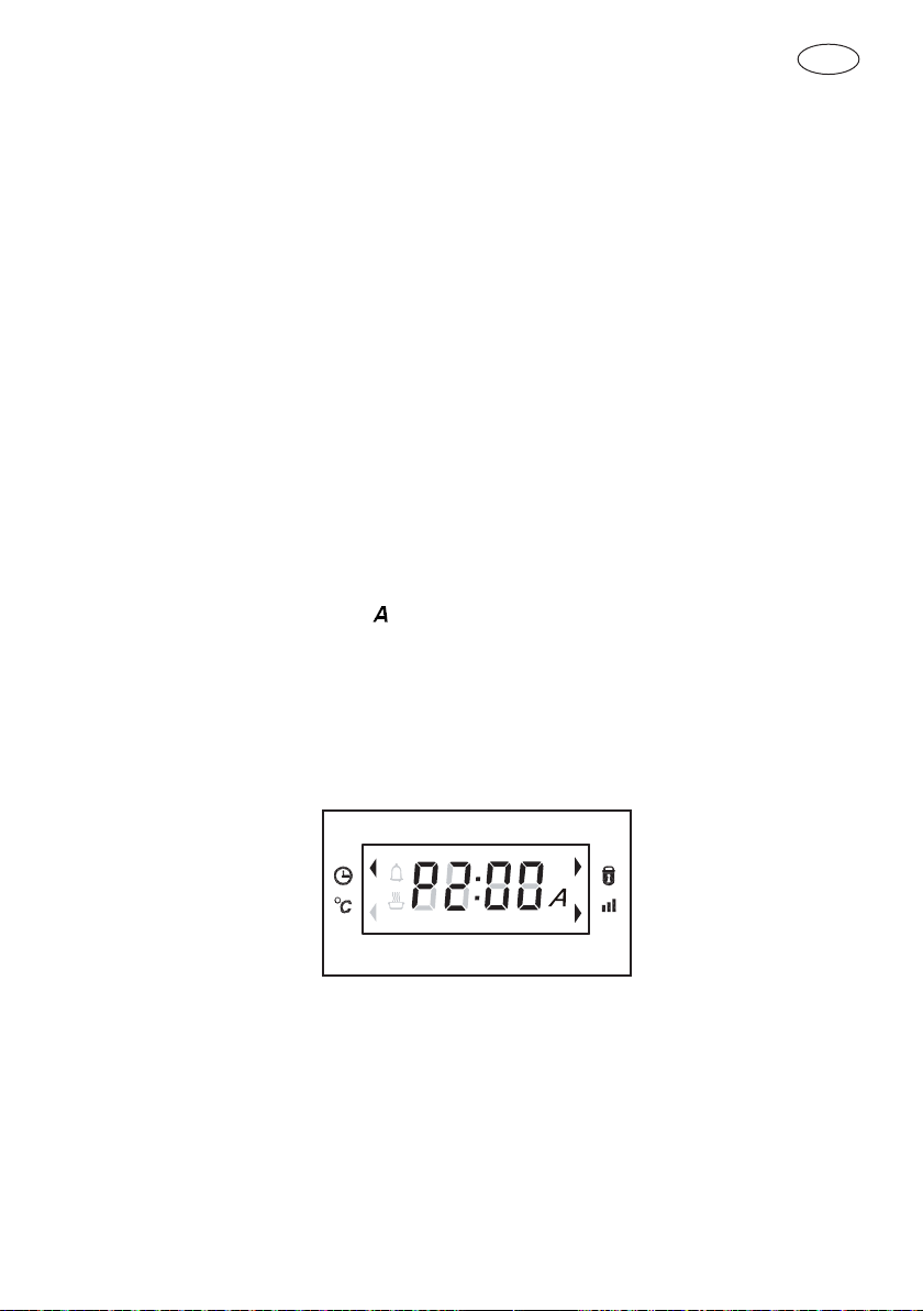
ELECTRONIC CONTROL
Control panel description (“EXTRA SMALL”)
The oven control panel is made with one display and two knobs.
- Time & Temperature display.
- Time & Temperature knob (Push & Shuttle).
- Mode (oven functions) knob.
TEMP & TIME MODE
The push & shuttle knob is mainly for clock or temperature setting and automatic time
functions programming. Select the desired item by pushing the knob.
Power-up
At every power-up, in pyrolytic ovens, the latch mechanism runs an automatic self-test:
the oven door locks and unlocks. This operation takes about half a minute. The lock led
turns on and flash while the action is in progress, it remains steadily displayed when the
door is fully locked, it’s off when the door has been unlocked.
Do not try to open the door until the lock led disappears.
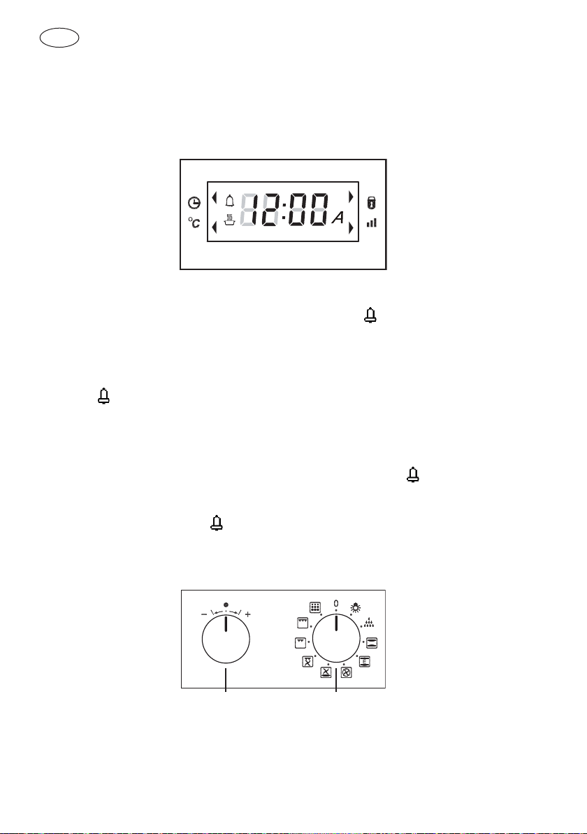
Programming time functions
At every power-up, the control shows the time of day blinking, set at 12:00 as the
initial value. The time increases every minute. The only possible action is the “Clock
Regulation”, all other oven operations are inhibited.
In general, turn the Temp/Time selector left or right in order to edit the values and
modify them by steps; hold the knob on the left or right to fasten the decrease/increase
operations.
Setting the time of day
The time of day is always displayed in the 24 hours format. Hours and minutes are set
separately. In order to set the time of day, mode selector must be in ZERO position, the
-/+ knob acts on the time of day by default.
GB
12
- Turn the selector left/right, the hours flash.
- Modify the flashing hours value turning the selector left/right.
- Push the Temp&Time selector to switch back and forth between hours and minutes.
- Modify the flashing minutes turning left/right.
- After a few seconds the whole time of day value starts flashing: wait until the new time
of day is steady.
Push the knob to toggle between the time of day and the minute minder and check
the set values. The clock is selected by default while the
symbol appears when the
minute minder is displayed.
Setting the minute minder
When the symbol is displayed, turn the knob left/right in order to set the timer value.
The standard value is 30 minutes, it’s possible to modify it in the range between 0 and
240 minutes.
This timer has no influence on the oven activities and can be set also when the oven
is off. The time of day is displayed with priority in any case, the symbol shows the
minute minder is active.
When the time expires, the symbol flashes and the buzzer sounds a warning
sequence (two short beeps repeated every 3 seconds) to recall the user attention. Push
the knob to stop it.
The buzzer stops in any case after a time-out.
TEMP & TIME
MODE

GB
13
Setting an oven function manually
Turn the mode knob into the desired position, the clock display shows On for a few
seconds. The oven will work for a maximum time (12hours). Depending on the oven
model, the number and type of available functions can be different.
If the selected function works using any heating elements, the
symbol is displayed
(it doesn’t appear in light and defrost position).
Turn the Temp & Time selector and set the desired oven temperature. The control
offers a PRESET temperature per every cooking mode or a full range between MIN and
MAX to be adjusted by hand. Check the value on the display after having selected the
temperature.
The temperature appears on the clock display for about 5 seconds when the Time &
Temp selector is pushed or when a new function has just been selected.
As soon as the oven starts, the preheat led (indicated by the bars) on the left side of the
clock display starts flashing and becomes steadily on when the preheat ends.
Turn the mode selector to ZERO (OFF) position to stop any activity, the display will show
OFF for a few seconds.
Setting an automatic oven function
After having selected a function as described before, the control can be programmed
in order to set timed cooking activities. The time program remains active even if the
function is changed (exception: pyrolyse). The following possibilities are available:
1 Timed cooking setting the cooking time (duration).
2 Timed cookitng setting the end of cooking time (stop time).
3 Delayed cooking setting duration and stop time.
Push the knob in order to toggle between cooking duration (cook time) and end of
cooking time (stop time): the words “dur” or “End” are displayed respectively.
Turn the knob left/right to edit the duration or the stop time when the proper word is
displayed:
1. When the word dur is displayed, the control shows 30’ as the standard cooking
duration. Turn the knob left/right in order to set the actually desired cooking time in a
range between 0 and 240 minutes. The display will flash dur
and its value alternatively
for a few seconds then it will show the time of day, the pot symbol and the
letter
to indicate that a timed cooking is active. The end of cooking time is updated
automatically.
2. When the word End is displayed, the control shows the current time as the initial stop
time. In order to set the actually desired end of cooking time in a 24 hours range:
GB
14
- Turn the knob left/right, the hours flash.
- Modify the flashing hours value turning the knob left/right.
- Push the knob to switch back and forth between hours and minutes or wait a few
seconds until the minutes flash.
- Modify the flashing minutes value the knob left/right.
- Wait until the new End of Cooking time value stops flashing.
The display will flash End and its value alternatively for a few seconds then it will show
the time of day, the
symbol and the letter to indicate that a timed cooking is
active. The cooking duration is updated automatically.
3. Repeat the same operations of point 1 then push the knob until End appears. the
control shows the “current time + cooking time” as the initial stop time. It’s not
possible to lower the end of cooking time below this value. In order to set the actually
desired end of cooking time in a 24 hours range:
- Turn the knob left/right, the hours flash.
- Modify the flashing hours value turning the knob left/right.
- Push the knob to switch back and forth between hours and minutes or wait a few
seconds until the minutes flash.
- Modify the flashing minutes value turning the knob left/right.
- Wait until the new End of Cooking time value stops flashing.
The display will flash End and its value alternatively for a few seconds then it will
show the time of day and the letter to indicate that a delayed cooking has been
programmed. As soon as the delay time expires, the oven starts and works for the
programmed cooking time.The
symbol is displayed.
At the end of any timed activity the control shuts down the oven, the buzzer sounds
a warning sequence (two short beeps repeated every 3 seconds) to recall the user
attention, for a maximum time and makes the time related icons (
, ) flash on the
display. Push the knob to silent the buzzer and reset the warning message.
Turn the mode selector to ZERO (OFF) position before reusing the oven.
Oven functions
The control can manage many cooking functions, here below described, their number
and availability depends on the oven model. The temperature range is between 50°C
and 250°C for most functions. Preset temperatures are mainly 190°C for convection
modes, 210°C for thermal modes and 230°C for grilling functions.
Exceptions are Eco-Bake (preset=190°C), Pyrolyse (fixed 475°C), and low temperature
modes (Light, Defrost, Keep Warm).
GB
15
Eco-Bake
This function is defined in order to obtain a consistent energy saving. The cooling fan is
initially off and turns on only when the inner parts temperature gets high. Cooking might
be a little bit slower than the standard Bake, especially when the oven is heavily loaded.
Defrost
This function is used to defrost frozen food in a short time. It doesn’t heat up the oven,
only the convection fan works. The temperature display shows dEF to indicate that this
special mode is active.
Pyrolyse (Self-Clean)
Turn the mode knob in the proper position to start a cleaning cycle. The temperature
display show the writing 475°.
The clean time can be set according to the same rules of the automatic functions, and
therefore the pyrolitic cycle can be delayed.
The maximum allowed clean time is 3 hours, the minimum 1 hour. The standard time
is 1h:30min, the clock display shows P1:30. At the end of the self-cleaning activity the
display shows P--- steady and
flashing. The writings on the display disappear when
the mode selector is placed in the ZERO position. The door remains locked until the
oven temperature drops below the safety threshold, at this time the control unlocks the
door.
The cooling fan starts as soon as the function is selected and turns to its higher speed
when the inner parts get hot. The oven temperature is automatically set to 475°C in
order to perfectly clean the cavity.
The control also locks immediately the door in order to guarantee the user safety, given
that the temperature inside gets very hot. A lock led (yellow) beside the temperature
display shows the status of the latch mechanism at any time:
- Door unlocked, lock led off.
- Door locked, lock led always on.
- Latch moving, transition in progress, lock led flashing.
To reuse the oven after a pyrolyse, turn the mode selector to ZERO (OFF) position.
GB
16
Door lock for children safety (pyro)
This is an additional safety functions available only in pyrolityc ovens. The door latch
mechanism that is managed automatically during pyrolyse can be actuated manually by
the user in order to lock the oven door and prevent children from having free access to
the oven.
Hold the Time&Temp knob for about 3 seconds to lock/unlock the door manually.
Commands lock for children safety (non pyro)
This is an additional safety functions available only in non pyrolityc ovens. Hold the
Time&Temp knob for about 3 seconds to lock the control panel commands and prevent
children from turning on the oven freely. Both knobs are disabled.
Buzzer volume
The buzzer volume can be set turning the Time&Temp knob left/right when the control
is in light mode. At any detents the buzzer sounds a double beep, selecting the volume
out of three available levels. The buzzer must always be silent between 22:00 and 8:00.
Failure declarations and error codes
The control is continuously checking the status of the system. If an abnormal condition
is detected for more than 1 minute, a failure occurs:
- The heaters and the other loads are disabled.
- The display shows a “E” letter followed by a numeric code that depends on the kind
of failure.
- The control emits an acoustic warning signal.
To reset a failure declaration, first remove the cause of the failure then turn the selector
to (ZERO) OFF.
Error code table.
Error Description
E1 Temperature sensor broken.
E2 Temperature sensor shorted.
E4 Temperature sensor circuit failure.
E8 Latch time-out overflow.
E16 Free.
E32 Free.
E64 Mode selector disconnected. Cannot be reset.
OTHER Sum of error codes simultaneously detected.
GB
17
Cooking mode table with preset, minimum, maximum temperatures (°C) and
nominal power (Watt)
N° MODE
PRESE
(°C)
TMIN
(°C)
TMAX
(°C)
HEATING
ELEMENTS (W)
NAME
0
0
ZERO
1
## ## ## LIGHT
2
80 50 100 400 KEEP WARM
3
210 50 250 2200 BAKE
4
210 50 250 2200 ECO-BAKE
5
210 50 250 1200 LOWER BAKE
6
## ## ## DEFROST
7
190 50 250 1200
LOWER
CONVECTION BAKE
8
190 50 250 2200 CONVECTION ROAST
9
190 50 250 2300 CONVECTION BAKE
10
230 50 250 2000 CONVECTION GRILL
11
230 50 250 2000 GRILL
12
230 50 250 2000 GRILL + TURNSPIT
13
230 50 250 3000 SUPER GRILL
14
475 2400 PYRO (THERMAL)
15
475 2400 PYRO
GB
18
DOOR LOCKING SYSTEM
Automatic door locking during pyrolytic cycle
For safety reasons, the door is locked automatically as soon as self-clean mode is
selected (both standard, both eco clean). The door is also unlocked automatically when
the clean time has expired but only after the temperature has fallen below the safety
threshold.
NOTE
It is not possible to exclude the door locking device during self-
cleaning i.e. manually unlock the door since the self-cleaning
mode has the highest priority and overrides all other selections.
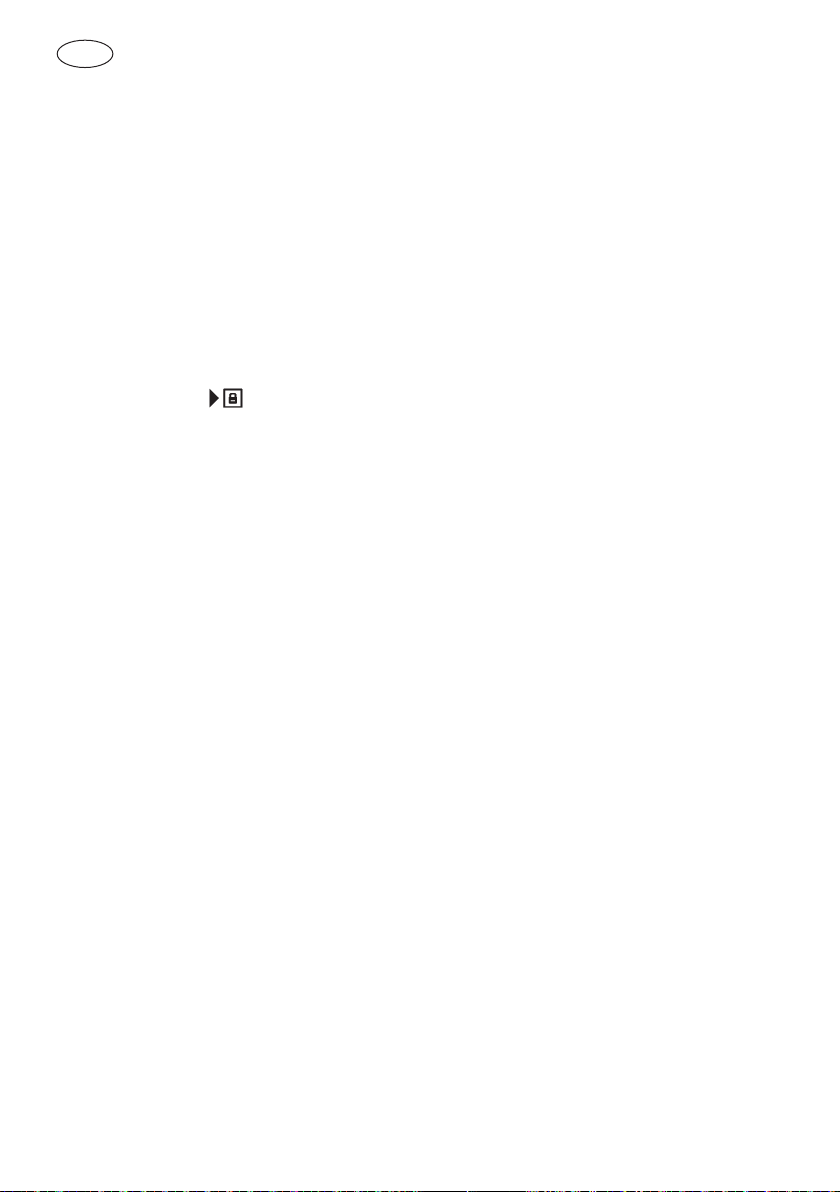
The lock symbol ( ) on the display is:
ON
When the door is fully locked
OFF
When the door is fully unlocked
FLASHING
When the latch mechanism is moving. (After self clean the sym
bol will flash until the temperature will be safe and the door
unlocked).
Oven lights
They turn on during all cooking activities but they are always disabled in self-clean.

GB
19
CLEANING AND MAINTENANCE
Prior to taking any action for cleaning, make sure the apparatus is cut-out from the
mains.
It is recommended that the oven interior be frequently cleaned. In particular, it should be
cleaned every time the grill is used to prevent excessive fouling of the oven interior that
may generate fumes or odours during subsequent cooking. Abrasive detergents and
steam cleaning equipment should not be used for cleaning.
WARNING
Do not use harsh abrasive cleaners or sharp metal scrapers to
clean the oven door glass since they can scratch the surface,
which may result in shattering of the glass.
Ovens provided with the hot air system are less subject to dirt inside.
Self-cleaning cycle (pyrolytic cycles)
Although it is not necessary to perform the cleaning operation each time the oven has
been used, do not let the oven get too dirty.
Before performing self-cleaning, take out all accessories (grills, dishes, pans) to avoid
damaging them, remove large cooking residues and then close the door,
ensuring that it is closed properly.
NOTE
Usually self-cleaning requires 2.30 to 3 hours according to the
amount of residue to be removed.
WARNING
Ensure that the door is in the closed position before the self-
cleaning cycle starts, otherwise automatic door locking will
not be completed. See paragraphs that follows.
When the cycle is finished and the oven has COOLED COMPLETELY, remove the
burned-off residues of the self-cleaning cycle with a damp cloth.
GB
20
Removing the “FULL GLASS” panoramic door
WARNING
Make sure that:
• The oven is cool and power to the oven has been turned off
before removing the door. Failure to do so could result in
electrical shock or burns.
• The oven door is heavy and fragile. Use both hands to
remove the oven door. The door front is glass. Handle care-
fully to avoid breakage.
• Grasp only the sides of the oven door. Do not grasp the
handle as it may swing in your hand and cause damage or
injury.
• Failure to grasp the oven door firmly and properly could
result in personal injury or product damage.
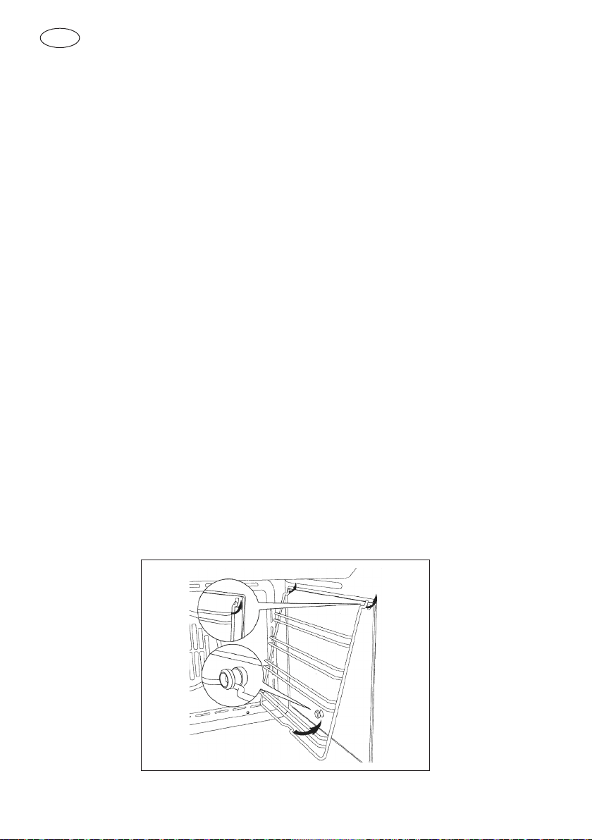
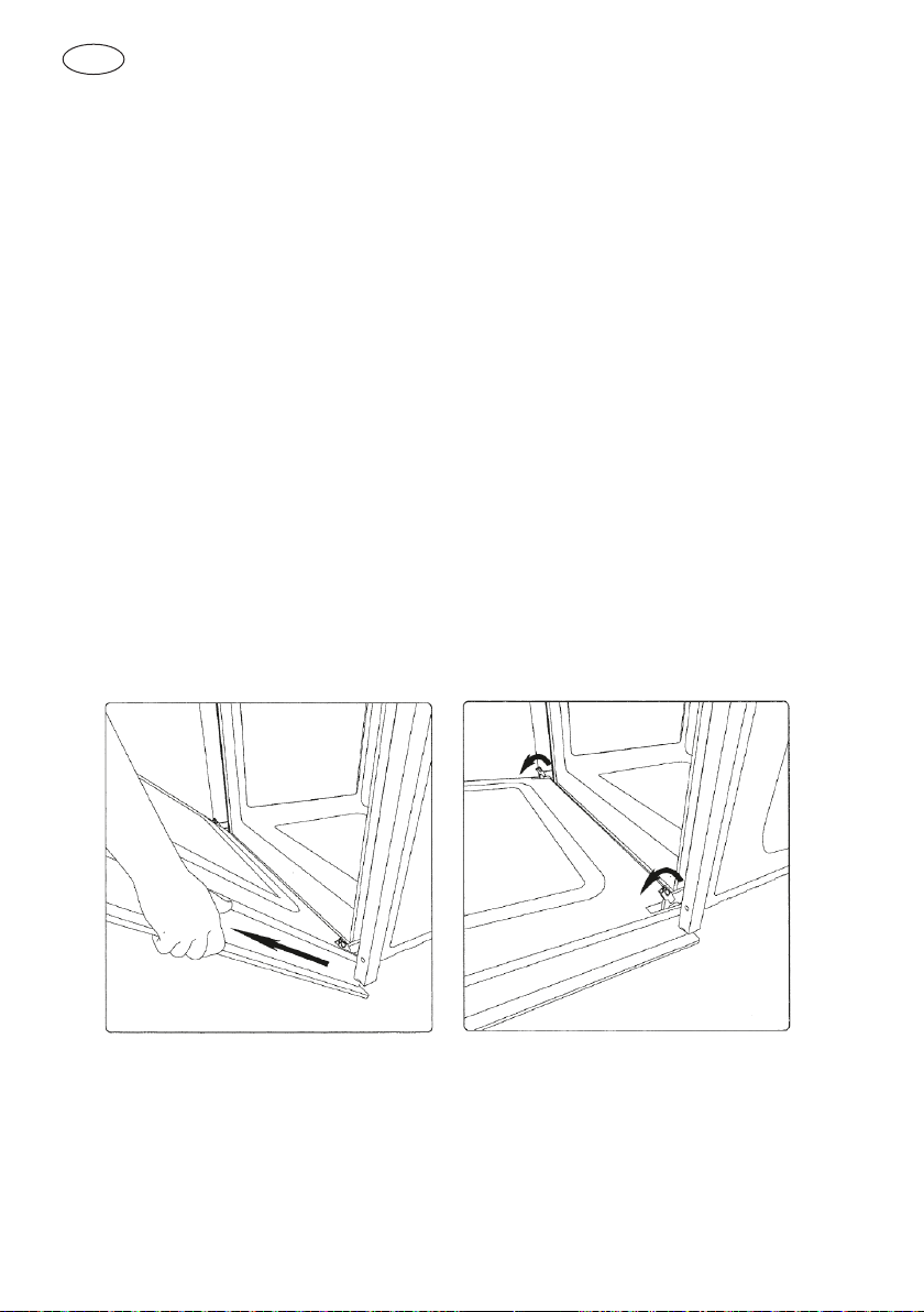
Removing the oven door
The oven door can be removed quickly and easily. To do so, proceed as follows:
- Open the door fully.
- Lift the two levers shown below.
- Close the door as far as the first stop (caused by the raised levers).
- Lift the door upwards and outwards to remove it fromits mountings.
To replace fit the door, fit the hinges in their mountings and lower the two levers
GB
21
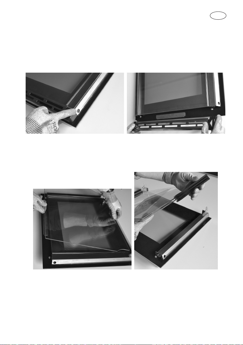
How to remove the inner glass of the “FULL GLASS” panoramic door
1. Wear protective gloves.
2. Place the door on a flat horizontal surface face down on a soft cloth to avoid scratching
the visible part.
3. Simultaneously press the keys of the two side covers, removing the upper strip.
4. Slide out the internal glass as shown below. Remove the second and third panes of
glass (middle panes) for cleaning sliding out the rubber strip.
GB
22
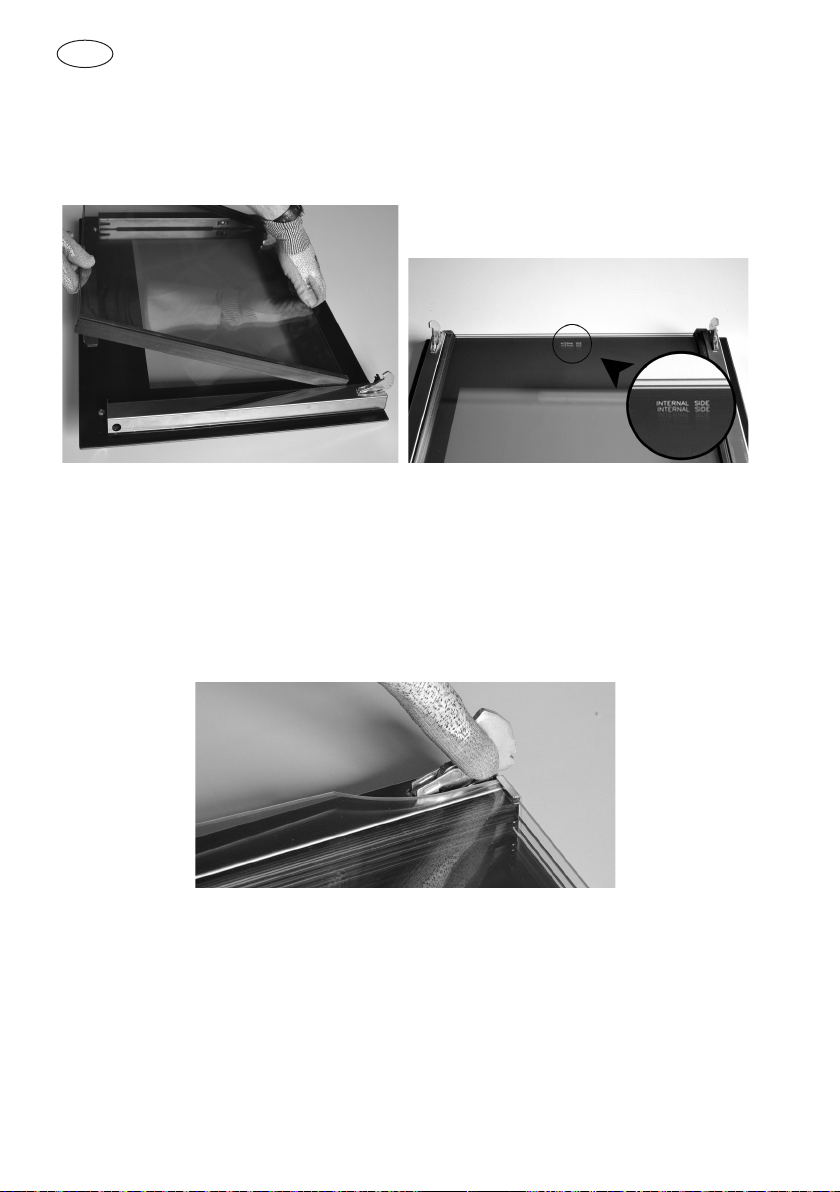
5. Replace the middle panes after cleaning in reverse order, checking that they are
oriented so the words INTERNAL SIDE are properly legible.
NOTE: a slight gap between the middle panes and the side supports is normal
because it allows for the heat expansion of the glass.
6. Place the pack of three glass panes between the two uprights and replace the top
strip.
GB
23
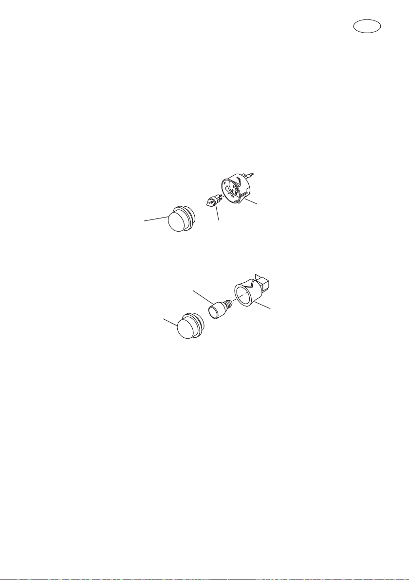
Replacement of the oven light
WARNING
Make sure that:
• The oven and lights are cool and power to the oven has been
turned off before replacing the light bulb(s). Failure to do so
could result in electrical shock or burns.
• The lenses must be in place when using the oven.
• The lenses serve to protect the light bulb from breaking.
• The lenses are made of glass. Handle carefully to avoid
breakage. Broken glass could cause an injury.
1
3
2
(230V - 25W G9)
1
3
(230V - 15 or 25W)
2
1 Turn off power at the main power supply (fuse or breaker box).
2 Remove the lens (1) by unscrewing it.
3 Remove the light bulb (2) from its socket (3).
4 Replace the bulb (2) with a new one. Avoid touching the bulb with fingers, as oils from
hands can damage the bulb when it becomes hot.
5 Use one with the same Volt and Watt (see figure).
6 Screw the lens (1) back on.
7 Turn power back on at the main power supply (fuse or breaker box).
GB
24
GUIDANCE TEMPERATURE AN TIME SCHEDULE
FOR COOKING
FOOD Mode
Rack
position
(from the
bottom)
Traditional cooking system Hot-air cooking system
Temperature
°C
Cooking
time in
minutes
Temperature
°C
Cooking
time in
minutes
Poork,calf (roast)
etc.
2nd 200 ÷ 225 100 ÷ 150 175 ÷ 180 90 ÷ 120
Filett, Roastbeef
2nd 240 ÷ 250 40 ÷ 50 210 ÷ 225 20 ÷ 30
Poultry (goose,
duck, turkey,
chicken) whole (4)
1st 190 ÷ 240 150 ÷ 180
180 ÷ 225 60 ÷ 75
Chicken
2nd 225 ÷ 250 30 ÷ 45 210 ÷ 225 45 ÷ 60
Hamburger,Chops
of Lamb, Chicken
thighs
3th 200 ÷ 220
10 ÷ 20
for each
side
180 ÷ 190
10 ÷ 15
for each side
Game (4)
1st 210 ÷ 230 80 ÷ 100 250 45 ÷ 60
Fish
1st 180 ÷ 190 35 ÷ 45 175 ÷ 180 35 ÷ 45
Cakes
1st 170 ÷ 200 40÷ 80 150 ÷ 170 35 ÷ 70
Biscuits
2nd 225 10 ÷ 20 170 ÷ 180 10 ÷ 15
Pizza
2nd 210 ÷ 240 15÷ 20 200 ÷ 210 10 ÷ 12
Pizza Multilevel
2nd & 3th
or 2nd & 4th
200 ÷ 210 15 ÷ 20
Warning for hot-air cooking - Position of pans:
- For cooking on 1 plane make use on 2nd holder from the bottom
- For cooking on 2 planes make use of 2nd - 4th holders from the bottom
- For cooking on 3 planes make use of 2nd - 3th and 4th holders from the bottom
- (4) The time depends of poultry dimension, (40 ÷ 45 mins for kg).
IMPORTANT: The cooking times are considered with oven preheated.

2.006.50.0 ed. 05-2016

Warranty Card
Eurolinx Pty Limited A.B.N. 50 001 473 347
trading as ILVE (“ILVE”)
Oce:
48-50 Moore Street, Leichhardt N.S.W 2040
Post:
Locked Bag 3000, Annandale, N.S.W 2038
P: 1300 856 411
WARRANTY REGISTRATION
Your ongoing satisfaction with your ILVE
product is important to us. We ask that you
complete the enclosed Warranty Registration
Card and return it to us so that we have a
record of the ILVE products you purchased.
Alternatively you can register on line (see
registration card for details)
PRIVACY
ILVE respects your privacy and is committed
to handling your personal information
in accordance with the National Privacy
Principles and the Privacy Act 1988 (Cth). A
copy of the ILVE Privacy Policy is available at
www.ilve.com.au. ILVE will not disclose any
personal information set out in the Warranty
Registration Card (“Personal Information”)
without your consent unless required by:
1. law;
2. any ILVE related company;
3. any service provider which provide services
to ILVE or assist ILVE in providing services
(including repair and warranty services) to
customers. Our purpose in collecting the
Personal Information is
to keep a record of the ILVE product
purchased by you, in order to provide a
better warranty service to you in the unlikely
event that there is a problem with your ILVE
product. ILVE may contact you at any one
or more of the address, email address or
telephone numbers set out in the Warranty
Registration Card. Please contact ILVE on
1300 694 583 should you not wish to be
contacted by ILVE.
WARRANTY
1. Warranty
ILVE warrants that each ILVE product will
remain, for a period of twenty four (24)
months computed from the date of purchase
of the ILVE product, free from defects
arising in the manufacture of the ILVE
product (“Warranty”). Except for consumer
guarantees set out in the Competition
and Consumer Act 2010 (Cth) (“Act”), ILVE
does not make any further warranties or
representations in relation to ILVE products.
2. What is not Covered by the Warranty.
The Warranty does not apply if an ILVE
product is defective by a factor other than a
defect arising in the manufacture of the ILVE
product, including but not limited to:
ilve.com.au
(a) damage through misuse (including failure
to maintain, service or use with proper care),
neglect, accident or ordinary wear and
tear (including deterioration of parts and
accessories and glass breakage);
(b) use for purpose for which the ILVE product
was not sold or designed;
(c) use or installation which is not in
accordance with any specied instructions for
use or installation;
(d) use or operation after a defect has
occurred or been discovered;
(e) damage through freight, transportation or
handling in transit (other than when ILVE is
responsible);
(f ) damage through exposure to chemicals,
dusts, residues, excessive voltage, heat,
atmospheric conditions or other forces or
environmental factors outside the control or
ILVE;
(g) repair, modication or tampering by the
purchaser or any person other than ILVE, an
employee of ILVE or an authorised ILVE service
contractor;
(h) use of parts, components or accessories
which have not been supplied or specically
approved by ILVE.
(i) damage to surface coatings caused by
cleaning or maintenance using products not
recommended in the ILVE product handbook
provided to the purchaser upon purchase of
the ILVE product;
(j) damage to the base of an electric oven due
to items having been placed on the base of
the oven cavity or covering the base, such as
aluminium foil (this impedes the transfer of
heat from the element to the oven cavity and
can result in irreparable damage); or
(k) damages, dents or other cosmetic
imperfections not aecting the performance
of the ILVE in respect of an ILVE product
purchased as a “factory second” or from
display.
The Warranty does not extend to light globes
used in ILVE products.
Customers must retain proof of purchase in
order to be eligible to make a warranty claim in
respect of an ILVE product.
6. Claiming under the Warranty
Customers will bear the cost of claiming
under this Warranty unless ILVE determines
the expenses are reasonable, in which case
the customer must claim those expenses by
providing written evidence of each expense to
ILVE at the address on the Warranty
Registration Card.
3. Domestic Use
Each ILVE product is made for domestic use.
This Warranty may not extend to ILVE products
used for commercial purposes; under those
circumstances the warranty period is limited to 3
month.
4. Time for Claim under the Warranty
You must make any claim under this Warranty
within twenty eight (28) days after the occurrence
of an event which gives rise to a claim pursuant
to the Warranty, by booking a service call on the
telephone number below.
5. Proof of Purchase
Customers must retain proof of purchase in order
to be eligible to make a warranty claim in respect
of an ILVE product.
6. Claiming under the Warranty
Customers will bear the cost of claiming under this
Warranty unless ILVE determines the expenses
are reasonable, in which case the customer
must claim those expenses by providing written
evidence of each expense to ILVE at the address
on the Warranty Registration Card.
7. Statutory Rights
(a) These terms and conditions do not a ect your
statutory rights.
(b) The limitations on the Warranty set out in this
document do not exclude or limit the application
of the
consumer guarantees set out in the Act or any
other
equivalent or corresponding legislation in the
relevant
jurisdiction where to do so would:
(i) contravene the law of the relevant jurisdiction;
or
(ii) cause any part of the Warranty to be void.
(c) ILVE excludes indirect or consequential loss
of any kind (including, without limitation, loss of
use of the
ILVE product) and (other than expressly provided
for in these terms and conditions) subject to all
terms,
conditions and warranties implied by custom,
the general law, the Act or other statute.
IMPORTANT!
All warranty service calls must be booked via
the customer care department. The team can
be contacted on 1 300 85 64 11 option 1 or
customercare@eurolinx.com.au
Service is delivered through a network of
Service Agents. If the Appliance is located
outside our normal Service Area of our agents
you, t he Customer will need to bear the cost
of travel outside that area.
If you are unable to provide proof of purchase,
the fault is not covered under warranty
or the product is found to be working to
specication you may be required to bear the
full cost of the service visit
01072016
Warranty Card continued
ilve.com.au
4ILVE Operating Manual
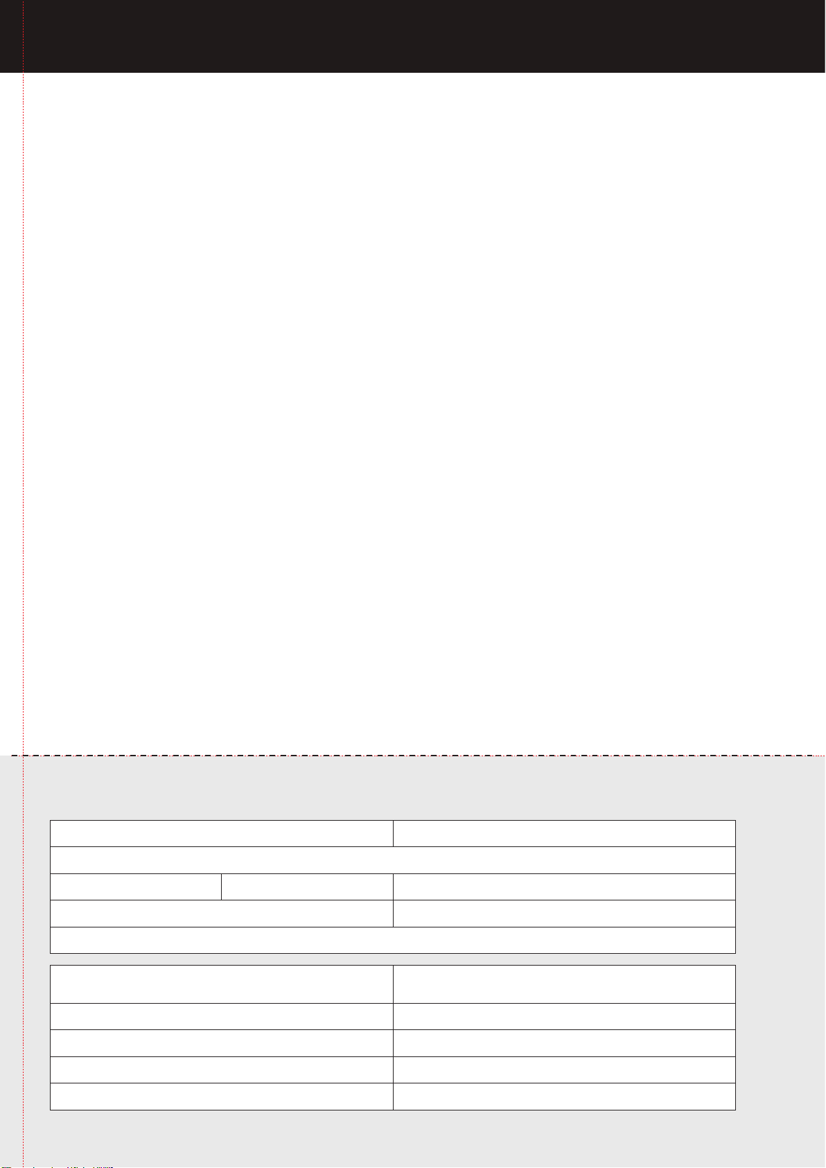
Please complete and send to ILVE at: REPLY PAID 83617
LEICHHARDT NSW 2040
Last Name: First Name:
Address:
State: Postcode: Email:
Home Phone: Mobile:
Purchase Date: / /
(Please attach proof of purchase to validate warranty)
MODEL NUMBER
SERIAL NUMBER
(if you cannot locate the serial number please call ILVE on 1300 85 64 11)
1
2
3
4
WARRANTY REGISTRATION CARD
01012013
01072016
Warranty Card tear off

Australia National Telephone Number 1300 MYILVE (694 583) New Zealand Telephone Number 0508 458 369
ILVE showrooms are open daily from 9am-5pm and Saturdays 10am-4pm
ilve.com.au
NSW & ACT (Head Ofce)
48-50 Moore Street
Leichhardt
F 02 8569 4699
VIC & SA
1211 Toorak Road
Camberwell
F 03 9809 2155
QLD
1/42 Cavendish Road
Coorparoo
F 07 3397 0850
WA & NT
Unit 10/55 Howe Street
Osborne Park
F 08 9201 9188
TAS (Crisp Ikin)
3 Pear Avenue
Derwent Park, 7009
P 03 6272 7386
New Zealand
PO Box 11.160
Sockburn Christchurch
F 03 344 5906