
INDOOR COOKING
Induction Range
KRI
Installation Manual
EN
©2020 Hestan Commercial Corporation
SAFETY DEFINITIONS
THIS INDICATES THAT DEATH OR SERIOUS INJURY MAY OCCUR
AS A RESULT OF NOT OBSERVING THIS WARNING.
THIS INDICATES THAT MINOR OR MODERATE INJURY MAY
OCCUR AS A RESULT OF NOT OBSERVING THIS WARNING.
THIS INDICATES THAT DAMAGE TO THE APPLIANCE OR
PROPERTY MAY OCCUR AS A RESULT OF NOT OBSERVING THIS
WARNING.
READ THESE INSTRUCTIONS CAREFULLY AND COMPLETELY BEFORE
INSTALLING OR USING YOUR APPLIANCE TO REDUCE THE RISK OF FIRE,
BURN HAZARD, OR OTHER INJURY. KEEP THIS MANUAL FOR FUTURE
REFERENCE.
CAUTION
NOTICE
Do not store or use gasoline or other flammable vapors and liquids in the vicinity of
this or any other appliance.
Installation and service must be performed by a qualified installer, service agency.
DO NOT REPAIR, REPLACE OR REMOVE ANY PART OF THE APPLIANCE UNLESS
SPECIFICALLY RECOMMENDED IN THE MANUAL. IMPROPER INSTALLATION,
SERVICE OR MAINTENANCE CAN CAUSE INJURY OR PROPERTY DAMAGE. REFER
TO THIS MANUAL FOR GUIDANCE. ALL OTHER SERVICING SHOULD BE DONE BY A
QUALIFIED TECHNICIAN.
IF THE INFORMATION IN THIS MANUAL IS NOT FOLLOWED EXACTLY,
A FIRE OR EXPLOSION MAY RESULT CAUSING PROPERTY DAMAGE,
PERSONAL INJURY, OR DEATH.
INSTALLER: LEAVE THIS MANUAL WITH THE OWNER OF THE APPLIANCE.
HOMEOWNER: RETAIN THIS MANUAL FOR FUTURE REFERENCE.
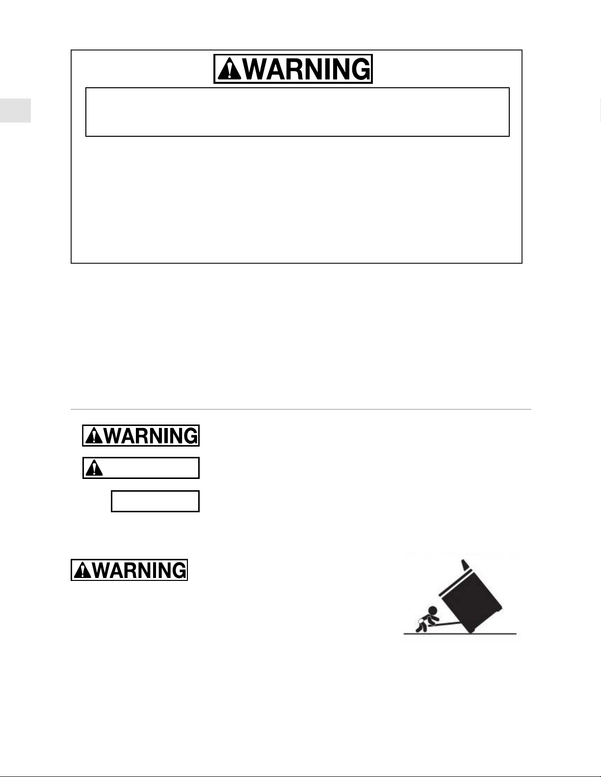
TIP OVER HAZARDTIP OVER HAZARD
A child or adult can tip over a range and be killed.
Check installation of the anti-tip device per the Installation Manual.
Do not operate the range without this device in place.
Check engagement of anti-tip device if range is moved, such as when cleaning behind the unit.
To check engagement, carefully tip the range forward while pulling from the rear of the unit. The
range should not move more that 1 inch [2.5cm].
Failure to follow these instructions can result in death or serious burns to children and adults.
To reduce the risk of burns, do not move this appliance while hot.
EN
©2021 Hestan Commercial Corporation
1
When properly cared for, your Hestan appliance will provide safe, reliable service for many years.
When using this appliance, basic safety practices must be followed as outlined below.
IMPORTANT: Save these instructions for the local Utility Inspector’s use.
INSTALLER: Please leave these Installation Instructions with the owner.
OWNER: Please retain these Installation Instructions for future reference.
This range is NOT designed for installation in manufactured (mobile) homes or recreational park
trailers. Do NOT install this range outdoors.
SAFETY PRECAUTIONS - BEFORE YOU BEGIN
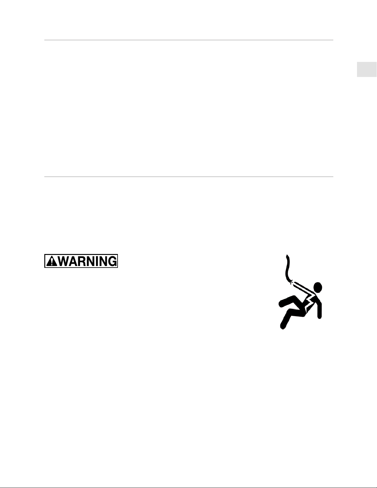
ELECTRICAL SHOCK HAZARDELECTRICAL SHOCK HAZARD
Disconnect power before installing or servicing appliance. Before turning
power ON, be sure all controls are in the OFF position. Failure to do so can
result in electrical shock or death.
ELECTRICAL GROUNDINGELECTRICAL GROUNDING
This appliance must be grounded. Grounding reduces the risk of electric
shock in the event of a short circuit. Read the ELECTRICAL CONNECTIONS
section of this manual for complete instructions.
This appliance is equipped with a 4-prong grounding plug for your protection against shock hazard
and should be directly plugged into a properly grounded receptacle. Do not cut or remove the
grounding prong from this plug.
• DO NOT ground to a gas pipe.
• DO NOT use an extension cord with this appliance.
• DO NOT have a fuse in the NEUTRAL or GROUNDING circuit. A fuse in the NEUTRAL or
GROUNDING circuit could result in an electrical shock.
ELECTRICAL SUPPLYELECTRICAL SUPPLY
The appliance must be on its own dedicated circuit - 240 VAC, Single Phase, 60 Hz, with a current
rating as shown in the model number listing on pg. 2. Have the installer show you where the
electric circuit breaker is located so you know how to shut off the power to this appliance. It is the
responsibility of the user to have the appliance connected by a licensed electrician in accordance
with all local codes, or in the absence of local codes, in accordance with the National Electrical Code.
Read the ELECTRICAL CONNECTIONS section of this manual for complete details.
TABLE OF CONTENTS
1 SAFETY PRECAUTIONS - BEFORE YOU BEGIN
2 MODEL NUMBERS
2 RATING LABEL
3 REGULATORY / CODE REQUIREMENTS
3 LOCATION AND INSTALLATION / VENTILATION
9 BACKGUARD AND ACCESSORIES
10 INSTALLATION OF ANTI-TIP DEVICE
11 ELECTRICAL CONNECTIONS
13 FINAL SETUP
14 SERVICE
14 APPENDIX
EN
©2021 Hestan Commercial Corporation
2
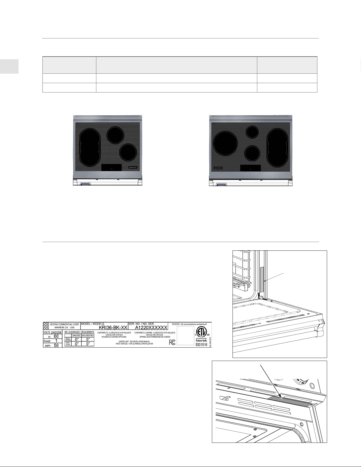
RATING
LABEL
MODEL NUMBERS
RATING LABEL
The rating label contains important information about your Hestan
appliance such as the model and serial number, electrical rating, and
the minimum installation clearances.
The rating label is located in one of two places, as shown in the
figures on this page.
If service is necessary, contact Hestan Customer Care with the
model and serial number information shown on the label.
RANGE MODELSRANGE MODELS
MODEL NO.MODEL NO. DESCRIPTIONDESCRIPTION
CIRCUIT BREAKER CIRCUIT BREAKER
REQUIREDREQUIRED
KRI30 30” INDUCTION RANGE WITH 4 ELEMENTS 50 Amp
KRI36 36” INDUCTION RANGE WITH 5 ELEMENTS 50 Amp
KRI36KRI36KRI30KRI30
RATING LABEL
KRI36 rating label shownKRI36 rating label shown

EN
©2021 Hestan Commercial Corporation
3
REGULATORY / CODE REQUIREMENTS
Installation of this cooking appliance must be made in accordance with local codes, or in the absence
of local codes with the National Electrical Code.
This appliance must be electrically grounded in accordance with local codes or in the absence of local
codes with the National Electrical Code
ANSI/NFPA 70
, or Canadian Electrical code
CSA C22.1
.
This appliance complies with part 18 of the FCC Rules. This equipment generates, uses and can
radiate radio frequency energy and, if not installed and used in accordance with the instructions,
may cause harmful interference to radio communications. However, there is no guarantee that
interference will not occur in a particular installation. If this equipment does cause harmful
interference to radio or television reception, which can be determined by turning the equipment
off and on, the user is encouraged to try to correct the interference by one or more of the following
measures:
• Reorient or relocate the receiving antennae.
• Increase the distance between the equipment and receiver.
• Connect the equipment into an outlet or a circuit different from that to which the receiver is
connected.
• Consult the dealer or an experienced radio/TV technician for help.
Persons who have heart pacemakers or other electronic implants should discuss with their doctor or
the manufacturer of the implant as to whether this device is sufficiently safe from interference.
LOCATION AND INSTALLATION / VENTILATION
UNPACKING AND PLACEMENTUNPACKING AND PLACEMENT
Remove the outer carton and packing materials from the shipping pallet. Do not remove the plastic
film covering the stainless-steel surfaces. This film protects the finish from scratches until the
appliance is installed in its final position.
Use extra caution with the ceramic glass top. It can crack or shatter if not handled with care. Move
the unit gently to avoid dropping or jarring the unit excessively which may damage the ceramic glass.
The unit is very heavy and should be handled with care. Use proper safety equipment, such as gloves,
and at least 2 persons to move the appliance into position to avoid injury and to avoid damage to the
floor or the appliance itself.
DO NOT USE A HAND TRUCK OR DOLLY ON THE FRONT OR REAR OF
THE RANGE. HANDLE AND MOVE FROM THE SIDES ONLY.
Do not lift or carry the appliance by the oven door or handle. This could
damage the door hinges.
NOTICE
EN
©2021 Hestan Commercial Corporation
4
LOCATION AND INSTALLATION / VENTILATION
(CONTINUED)
The range is held onto the pallet with 4 large shipping bolts on both sides. Remove these bolts and
then move the range to the floor with the help of 2 persons.
PREPARATION PREPARATION
Before moving the range, protect any finished flooring and secure the oven door(s) closed to prevent
damage.
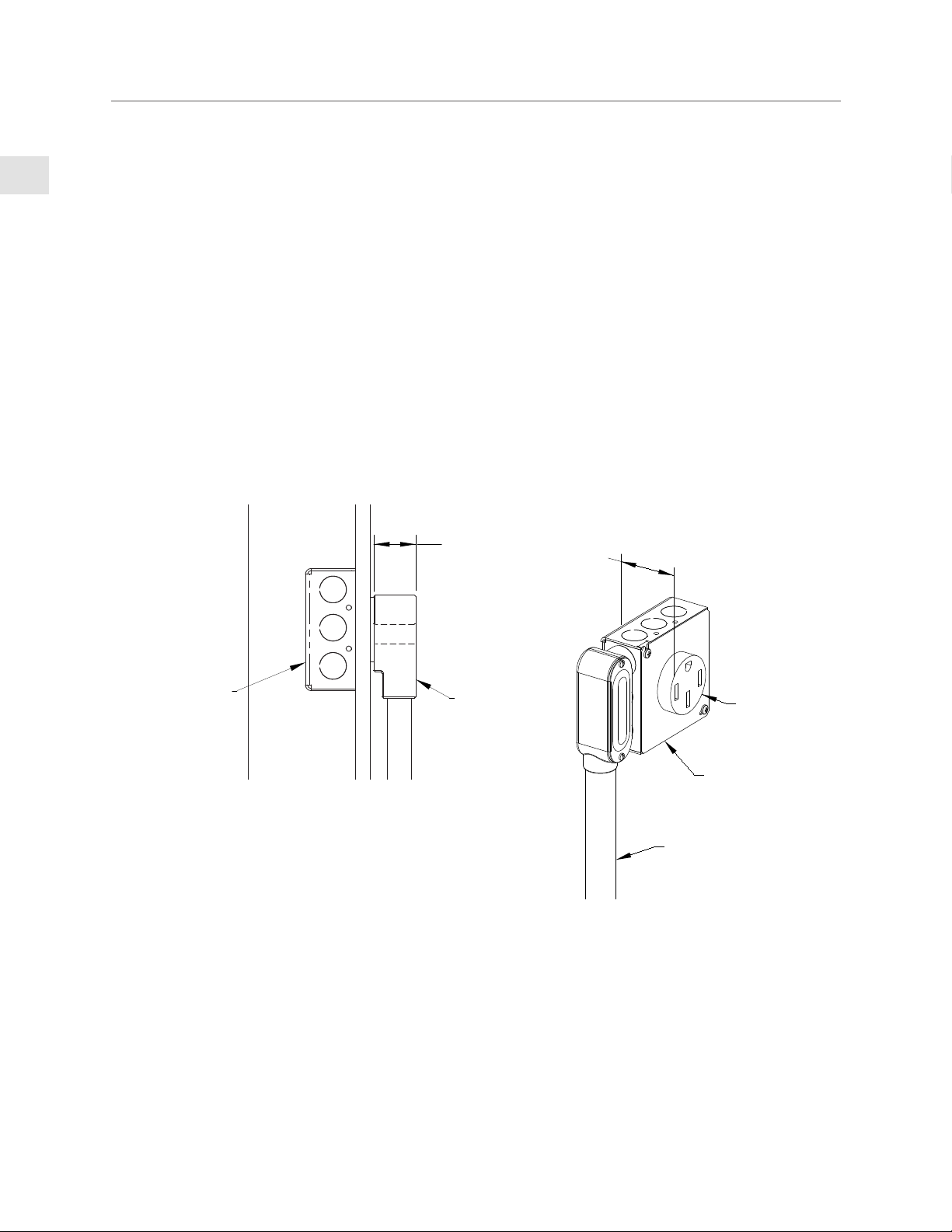
ELECTRICAL SUPPLY CLEARANCESELECTRICAL SUPPLY CLEARANCES
If not already in place, install the power receptacle / junction box as shown in the Installation
Clearances on the following pages. Any openings in the wall or floor behind the appliance must be
sealed.
The range is designed to be installed nearly flush to the rear wall*. It may be necessary to reposition
the power receptacle / junction box in order to accommodate the range when pushed back against
the wall.
Wall-mounted junction box may protrude no more than 2-3/8” [6.1 cm] from wall and still allow the
back of the range to be nearly flush to rear wall.
* Unless installed in an island with no rear wall.
1-5/16"
[3.3 cm]
POWER
CORD
JUNCTION BOX
INSIDE WALL
CABINETRYCABINETRY
To eliminate the risk of burns or fire by reaching over heated surface units, cabinet storage space
located above the surface units should be avoided. If cabinet storage is to be provided, the risk can
be reduced by installing the required vent hood that projects horizontally a minimum of 5” [12.7 cm]
beyond the bottom of the cabinets.
2"
[5.1 cm]
RECEPTACLE
NEMA 14-50
JUNCTION
BOX
CONDUIT

EN
©2021 Hestan Commercial Corporation
5
OVEN DOOR REMOVAL OVEN DOOR REMOVAL
If you have a very narrow door opening to your kitchen, the oven door(s) can be removed. REMOVE
ONLY IF ABSOLUTELY NECESSARY. Door removal should only be done by a certified installer or
service technician. Be sure the oven has completely cooled and the electrical power is off. Failure
to do so may result in electric shock or burn injury. Use caution when removing the door, it is very
heavy. Be careful to disconnect the wire inside the door.
1. Open oven door completely.
2. Locate cover near hinge to access wire connector inside. Using small needle-nose pliers and a
small flat-blade screwdriver, disconnect the wires inside the door. [ A ]
3. At each hinge location, swing the hinge clip forward until it stops. A screwdriver may be needed
to do this. [ B ]
4. Gently close the oven door until it stops against the hinge clips, or approximately 30° from the
closed position. Hold on firmly to both sides of the door (not the handle) and pull the door
straight up off the hinges. Ask an assistant to help direct the wires out of the bottom of the door
so it does not hang up on anything. Place the oven door in a safe location until needed. NEVER
release the hinge clips and try to close the hinges. Doing so will snap the hinges closed with
great force which could cause injury. [ C & D ]
COVER PLATE
AND SCREW
HINGE CLIP
A
B
Hinge
clip
C
F
G
H
LOCATION AND INSTALLATION/VENTILATION
(CONTINUED)
RE-INSTALL OVEN DOORRE-INSTALL OVEN DOOR
1. Hold the door firmly on both sides (NOT FROM THE HANDLE) at approximately 30° from the
closed position and insert the hinges into the slots in the oven. The bottom edge of each hinge
has a notch which must seat inside the slot opening. DO NOT FORCE OR BEND OR TWIST
THE DOOR! [ E & F ]
2. Slowly open the door all the way. Swing the hinge clips away from you until completely inside
the slot opening and fully seated. A screwdriver may help you do this. [ G ]
3. Re-attach the wire connector and assure it is securely inside the door. Re-install the cover. [ H ]
4. Gently close the oven door to check for smooth operation.
EN
©2021 Hestan Commercial Corporation
6
LOCATION AND INSTALLATION/VENTILATION
(CONTINUED)
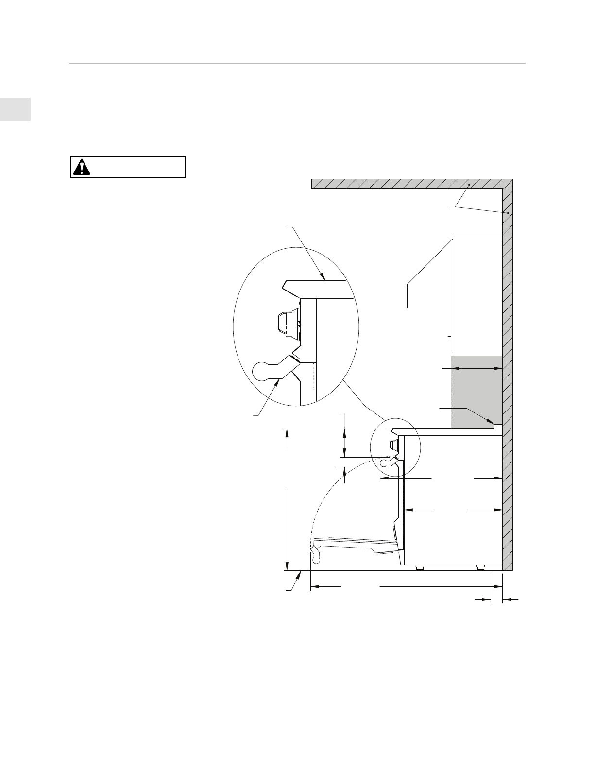
LEVELINGLEVELING
The range must be level. Raise or lower the range to the desired height by adjusting the leveling legs
under the range. The legs can be turned by hand. It may be necessary to use a lever or other lifting
device to assist in temporarily raising the unit to turn the legs. Do not lift or lever from the front or
back, only from the sides.
The appliance top must
be level with or higher
than the adjacent
countertop surfaces.
Failure to adjust the
height may expose the
adjacent cabinets to
excessive heat which may
damage the cabinets or
countertop.
CAUTION
35-3/4 - 37-1/4”
[90.8 - 94.6]
TO COOKING
SURFACE
APPLIANCE TOP /
COOKING SURFACE
HANDLE
END CAP
COMBUSTIBLE
MATERIALS
30-13/16”
[78.3]
24-11/16”
[62.7]
13” [33]
2-5/8”
[6.7]
MAX.
ISLAND TRIM
BACKGUARD
SHOWN
MAX.
RECESS
DEPTH
FINISHED
FLOOR
48-5/16”
[122.7]
3”
[7.6]
DIMENSIONS IN BRACKETS [ ] ARE IN CM.
LOCATION OF GAS AND
ELECTRICAL ON FLOOR
INSTALLATION CLEARANCES - ALL BACKGUARDS
SIDE VIEW
5-7/8”
[14.9]
VENT
HOOD
EN
©2021 Hestan Commercial Corporation
7
LOCATION AND INSTALLATION/VENTILATION
(CONTINUED)
E
W
V
18" [45.7]
MIN.
7"
[17.8]
11"
[27.9]
2-1/2"
[6.4]
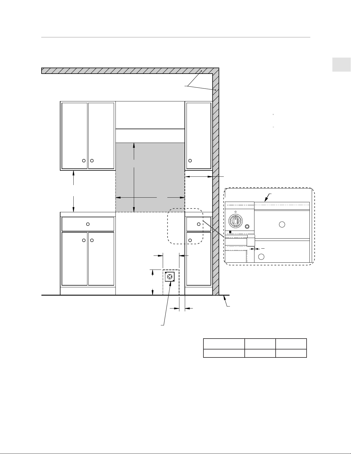
INSTALLATION CLEARANCES 30” - ALL BACKGUARDS
COMBUSTIBLE
MATERIALS
VENT HOOD
DIMENSIONS IN
BRACKETS [ ] ARE
IN CM.
FRONT VIEW
COUNTERTOP
FULL OVERLAY
DRAWER FACE
FULL OVERLAY
CABINET DOOR FACE
ELECTRICAL
SUPPLY
LOCATION
FINISHED
FLOOR
1
8
"
[3.2 mm]
ZERO CLEARANCE
ALLOWED TO NEAREST
COMBUSTIBLE SIDE
SURFACE
RANGE MODEL
W
V (MIN)
KRI30 30” [76.2] 30” [76.2]
NOTES:
• SHADED AREAS INDICATE WHERE COMBUSTIBLE MATERIALS ARE NOT ALLOWED.
• APPLIANCE TOP MUST BE LEVEL OR HIGHER THAN THE ADJACENT COUNTERTOP SURFACES.
• “E” IS ELECTRICAL SUPPLY ZONE.
• “W” IS APPLIANCE OPENING.
NOTE: HANDLE END CAPS PROTRUDE 1/8” BEYOND EACH SIDE OF THE RANGE. ALLOWANCE MAY BE
NEEDED FOR ADJACENT DRAWERS OR CABINETRY.
• “V” IS MIN. CLEARANCE TO VENTILATION HOOD.

EN
©2021 Hestan Commercial Corporation
8
LOCATION AND INSTALLATION/VENTILATION
(CONTINUED)
W
V
E
VENT HOOD
COMBUSTIBLE
MATERIALS
2-1/2”
[6.4]
6”
[15.2]
5”
[12.7]
FINISHED
FLOOR
DIMENSIONS IN
BRACKETS [ ] ARE
IN CM.
19”
[48.3]
[24.1]
ELECTRICAL
SUPPLY
LOCATION
18” [45.7]
MIN.
9-1/2”
COUNTERTOP
FULL OVERLAY
DRAWER FACE
FULL OVERLAY
CABINET DOOR FACE
INSTALLATION CLEARANCES 36” - ALL BACKGUARDS
FRONT VIEW
1
8
"
[3.2 mm]
ZERO CLEARANCE
ALLOWED TO NEAREST
COMBUSTIBLE SIDE
SURFACE
RANGE MODEL
W
V (MIN)
KRI36 36” [91.4] 30” [76.2]
NOTES:
• SHADED AREAS INDICATE WHERE COMBUSTIBLE MATERIALS ARE NOT ALLOWED.
• APPLIANCE TOP MUST BE LEVEL OR HIGHER THAN THE ADJACENT COUNTERTOP SURFACES.
• “E” IS ELECTRICAL SUPPLY ZONE.
• “W” IS APPLIANCE OPENING.
NOTE: HANDLE END CAPS PROTRUDE 1/8” BEYOND EACH SIDE OF THE RANGE. ALLOWANCE MAY BE
NEEDED FOR ADJACENT DRAWERS OR CABINETRY.
• “V” IS MIN. CLEARANCE TO VENTILATION HOOD.
EN
©2021 Hestan Commercial Corporation
9
LOCATION AND INSTALLATION/VENTILATION
(CONTINUED)
BACKGUARD AND ACCESSORIES
Sheetmetal accessories such as the backguard, and areas at the rear of the range may have sharp
edges. Wear work gloves while handling and installing these items.
BACKGUARDBACKGUARD
Your Hestan range is supplied at the factory with an Island Trim backguard. See Table 1 in the
APPENDIX section of this manual for other backguard options available from your Hestan dealer.
Selection of the appropriate backguard depends on the installation location and adjacent materials,
and the type of vent hood to be used. Installation instructions are included with the backguard kit.
The top of the backguard serves as an exhaust for the oven when in operation, and as an exhaust vent
to remove heat from under the cooktop section of the range as well. DO NOT BLOCK or obstruct
the top of the backguard. DO NOT touch the top of the backguard during appliance operation as it
may get hot. Allow sufficient time to cool before touching or cleaning this area.
DO NOT position plastic or other heat-sensitive items nearby which could melt or burn.
CAUTION
VENTILATIONVENTILATION
It is strongly recommended that this appliance be installed with a Hestan vent hood. While this
unit does not have the high heat output of a traditional gas range, evacuation of steam, vapors, and
cooking odors is still desirable. It is very important that the hood and ductwork installation meets
local building codes and is installed by a qualified technician.
Do not use a down-draft style ventilation system.
Do not mount a microwave oven/ventilator combination above the range. These type of units do not
typically have sufficient airflow and were not tested with this type of appliance.
For non-Hestan approved vent hoods, the vent hood and/or blower unit must be rated for at least
300 CFM for 30” and 36” induction range sizes.
For island applications, it is recommended to use a vent hood that is 6” [15.2 cm] wider than the
appliance, to allow for 3” [7.6 cm] of overlap on the left and right of the appliance.
Keep duct runs as short and straight as possible. Elbows and transition fittings reduce airflow
efficiency. Hestan recommends keeping the duct run under 50 ft. [15.2 m].
CONSULT WITH YOUR HESTAN DEALER ON SELECTING THE APPROPRIATE
VENT HOOD FOR YOUR HESTAN APPLIANCE.
CAUTION

EN
©2021 Hestan Commercial Corporation
10
INSTALLATION OF ANTI-TIP DEVICE
THE ANTI-TIP DEVICE PROVIDED WITH THIS RANGE
MUST BE INSTALLED.
PREPARATIONPREPARATION
POSSIBLE PROPERTY DAMAGE - Use a qualified installer or contractor to
determine the proper method of attaching the anti-tip bracket to the rear wall
or floor behind your range. Special drills or tools may be needed to drill holes in the wall or floor
(ceramic tile, hardwood flooring, etc.).
ELECTRICAL SHOCK HAZARD - Use extreme caution when drilling
holes into the wall or floor as there may be hidden wires. Identify the
electrical circuits that could be affected by the installation of the anti-tip
bracket. Shut off the power to these circuits. Failure to follow these instructions may result in death
or electrical shock.
HOLE PREPARATIONHOLE PREPARATION
The anti-tip bracket must be installed in sound materials, such as wood studs in the wall AND floor
joists under the finished floor. They must be able to withstand the forces exerted on the bracket by
the range should it tip-over. If wood studs or other suitable materials are not in the designated area
behind the range, you must attach the bracket using appropriate drywall anchors or similar fasteners.
DRYWALL INSTALLATION: After positioning the bracket as per the diagram below, mark the holes
and drill the appropriate holes as per the instructions supplied with the wall anchors. For hardboard
or solid plaster walls, you may need different wall anchors, available at your local hardware store or
home center.
WOOD FLOOR INSTALLATION: After positioning the bracket as per the diagram below, mark the
holes and drill the appropriate holes for #12 or similar, large wood screws, at least 1.5” [3.8 cm] in
length. Use washers as well. All hardware is available at your local hardware store or home center.
CONCRETE FLOOR INSTALLATION: After positioning the bracket as per the diagram below, mark
the holes and drill the appropriate holes for #12 or similar large masonry anchors, at least 1.5” [3.8 cm]
in length. Use washers as well. All hardware is available at your local hardware store or home center.
NOTICE
X
RANGE MODEL
XX
KRI30, KRI36 1-1/16” [2.7]

EN
©2021 Hestan Commercial Corporation
11
INSTALLATION OF ANTI-TIP DEVICE
(CONTINUED)
ANTI-TIP BOLT ADJUSTMENTANTI-TIP BOLT ADJUSTMENT
After leveling the range, and after the bracket has been attached, adjust the anti-tip bolt and large
washer under the range so the top of the washer is 1-1/4” [3.2 cm] maximum from the floor. Slide
the range into the opening of the bracket and verify the bolt is engaged in the bracket as seen
below. Carefully tip the range forward to check. The range should not move more than 1” [2.5 cm].
ELECTRICAL CONNECTIONS
ELECTRICAL SHOCK HAZARDELECTRICAL SHOCK HAZARD
Disconnect power before installing or servicing appliance. Before turning
power ON, be sure all controls are in the OFF position. Failure to do so can
result in electrical shock or death.
ELECTRICAL GROUNDINGELECTRICAL GROUNDING
This appliance must be grounded. Grounding reduces the risk of electric
shock in the event of a short circuit. Grounding through the neutral conductor is prohibited for
new branch circuit installations (1996 NEC), mobile homes, and recreational vehicles, or in an area
where local codes prohibit it. This range has been setup at the factory for a 4-wire connection.
CAUTION
Improper grounding will cause malfunctions in the unit. This can
damage the appliance and create a shock hazard condition.
ELECTRICAL CONNECTIONELECTRICAL CONNECTION
The appliance must be connected using the cordset provided. The appliance must be on its own
dedicated circuit - 240 VAC, Single Phase, 60 Hz, with a current rating as shown in the model
number listing on page 2. The installation must be done in accordance with local codes, or in the
absence of local codes, it must be installed in accordance with the National Electrical Code, ANSI/
NFPA 70.
For both US and CANADA installations: This appliance is equipped
with copper lead wires and must be connected to copper wires only.
Improper connection of aluminum house wiring can result in a fire or
shock hazard. Use only connectors designed and certified for
connecting to aluminum wire, and installed by a qualified electrician.

EN
©2021 Hestan Commercial Corporation
12
4-WIRE CONNECTION4-WIRE CONNECTION
For installations where grounding through the neutral
conductor is prohibited. Use only 4-conductor cord
kits rated 125/250 Volts (min), 50 Amps, and labeled
“For Use with Ranges”. Your Hestan range is pre-wired
at the factory for a 4-wire connection and includes this
cordset.
1. Make sure power is off at the supply panel /
breaker.
2. Remove the narrow access panel at the rear of
the range and locate the chassis ground terminal.
Attach GREEN ground appliance wire of supply
circuit or cord to chassis using ground screw.
3. Connect WHITE neutral appliance wire to WHITE
neutral wire in electrical box.
4. Connect RED (L1) appliance wire to RED power
wire in electrical box.
5. Connect BLACK (L2) appliance wire to BLACK
power wire in electrical box.
6. Tighten all connections. Strain relief must be
installed.
STRAIN RELIEF /
BRIDE DE CORDON
POWER CORD /
CORDON D’ALIMENTATION
GROUND TERMINAL /
BLOC DE MISE
À LA TERRE
3-WIRE CONNECTION3-WIRE CONNECTION
For installations where grounding through the neutral
conductor is allowed. Use only 3-conductor cord kits
rated 125/250 Volts (min), 50 Amps, and labeled “For
Use with Ranges”. This cordset is available at hardware
stores and home centers.
1. Make sure power is off at the supply panel / breaker
off.
2. Attach WHITE neutral appliance wire to WHITE
neutral wire in electrical box and use GREEN
ground jumper wire to connect to neutral as shown
here.
3. Connect RED (L1) appliance wire to RED power
wire in electrical box.
4. Connect BLACK (L2) appliance wire to BLACK
power wire in electrical box.
5. Tighten all connections. Strain relief must be
installed.
STRAIN RELIEF /
BRIDE DE CORDON
POWER CORD /
CORDON D’ALIMNENTATION
GROUND TERMINAL /
BLOC DE MISE
À LA TERRE
JUMPER WIRE /
FIL CONNECTEUR
ELECTRICAL CONNECTIONS
(CONTINUED)

EN
©2021 Hestan Commercial Corporation
13
FINAL SETUP
Remove any final packaging materials, and protective film from all exterior areas. Check inside oven
for other packaging items, tape on oven racks, etc.
Before testing operation of the appliance, verify electrical power has been restored to the unit.
NOTICE
All the control knobs must be in the OFF position to prevent unintended operation at power up. To
ensure customer safety in the event of a power failure, the range will display an error message when
the power is restored unless all the knobs are in the OFF position. Set all the knobs to OFF, and
reset the breaker to clear the error message.
DO NOT ATTEMPT TO USE THE RANGE DURING A PROLONGED POWER FAILURE.
FUNCTIONAL TESTFUNCTIONAL TEST
1. Fill an induction-capable cooking utensil with 1/2 - 1” [1.2-2.5 cm] of water and place it on one of
the cooking zones.
2. Switch the control ON by touching the [ON OFF] key(1).
• If the commands are locked, touch the lock key (10) for a few seconds. The lock is deactivated
and the controls should respond.
3. Touch the zone select key (5) for the cook zone where the utensil is.
4. Touch the power slider and set it to a level between 3 and 9.
5. Observe that the display responds to the power setting, and observe that the cooking utensil
begins to heat up.
6. Touch the selector key (5) for that zone to turn it off.
7. Touch the [ON OFF] key to turn the rangetop off.
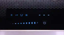
USER INTERFACE
1 ON/OFF 7 Timer clock indicator (for each zone)
2 Power slider - minimum power 8 Selection indicator dot
3 Power slider - maximum power 9 Pause / Recall Function
4 Power Booster (P) 10 Key Lock Function
5 Cooking Zone displays 11 Chef Cook Function
6 Timer display and + / - setting keys 12 Warming Function
CRITERIACRITERIA
If the controls respond as described and the utensil heats up, then the test is successful.
2 53 4 1
9 10 11 12 6 7 8
EN
©2021 Hestan Commercial Corporation
14
APPENDIX
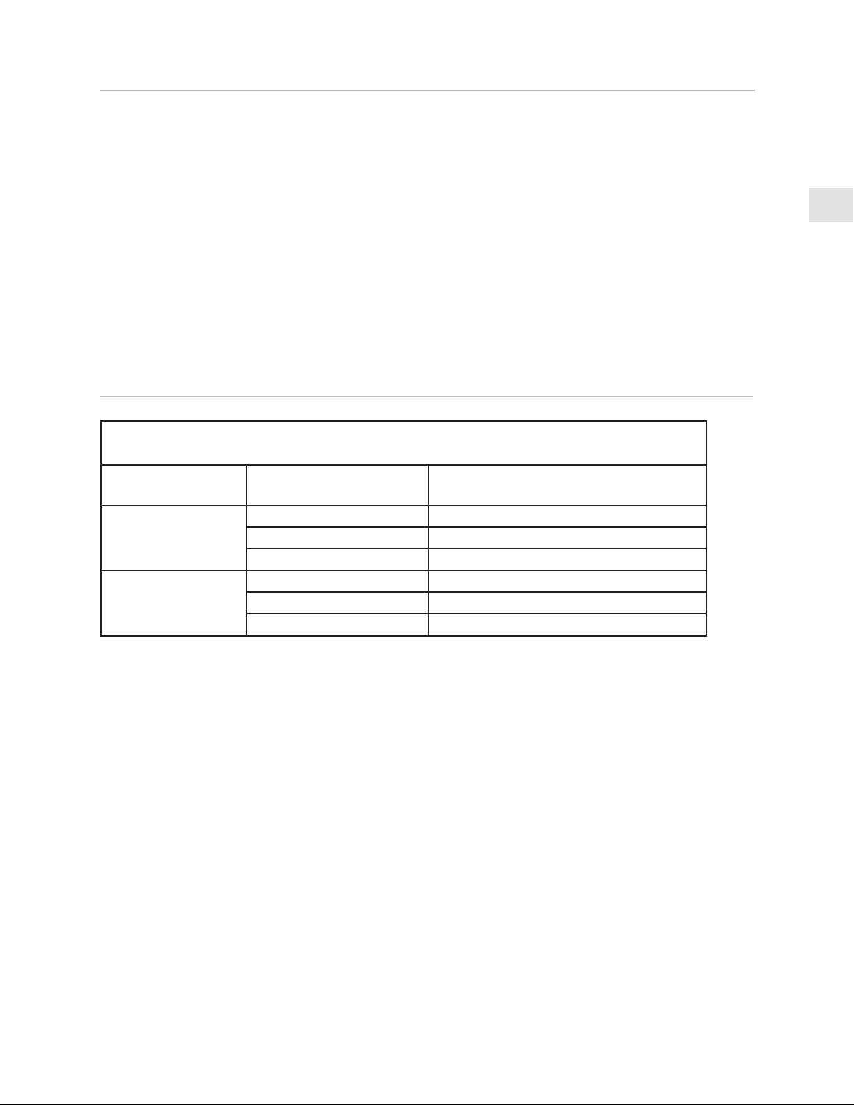
TABLE 1 - BACKGUARD OPTIONSTABLE 1 - BACKGUARD OPTIONS
RANGE MODELRANGE MODEL BACKGUARD MODELBACKGUARD MODEL DESCRIPTIONDESCRIPTION
KRI30 KBGIT30* BACKGUARD, ISLAND TRIM, 30”
KBGLB30 BACKGUARD, LOW BACK, 30”
KBGHS30 BACKGUARD, HIGH SHELF, 30”
KRI36 KBGIT36* BACKGUARD, ISLAND TRIM, 36”
KBGLB36 BACKGUARD, LOW BACK, 36”
KBGHS36 BACKGUARD, HIGH SHELF, 36”
* INCLUDED WITH RANGE
SERVICE
Toutes les réparations sous garantie et hors garantie doivent être effectuées par un technicien qualifié.
Pour trouver un réparateur agrée dans votre région, contactez votre concessionnaire Hestan, votre
représentant local, ou Hestan. Avant d’appeler, veuillez avoir sous la main le numéro de modèle et le
numéro de série.
Hestan Commercial Corporation
3375 E. La Palma Avenue
Anaheim, CA 92806
(888) 905-7463
DÉFINITIONS DE SÉCURITÉ
CECI INDIQUE QUE L’INOBSERVATION DE CET AVERTISSEMENT
PEUT ENTRAÎNER DES BLESSURES GRAVES VOIRE MORTELLES.
CECI INDIQUE QUE L’INOBSERVATION DE CET AVERTISSEMENT
PEUT ENTRAÎNER DES BLESSURES MINEURES OU MODÉRÉES.
CECI INDIQUE QUE L’INOBSERVATION DE CET AVERTISSEMENT
PEUT ENTRAÎNER DES DOMMAGES DE L’APPAREIL OU DES
DÉGÂTS MATÉRIELS.
PRÉCAUTION
AVIS
INSTALLATEUR: LAISSER CE MANUEL AVEC LE PROPRIÉTAIRE DE L’APPAREIL.
PROPRIÉTAIRE: CONSERVEZ CE MANUEL POUR RÉFÉRENCE FUTURE.
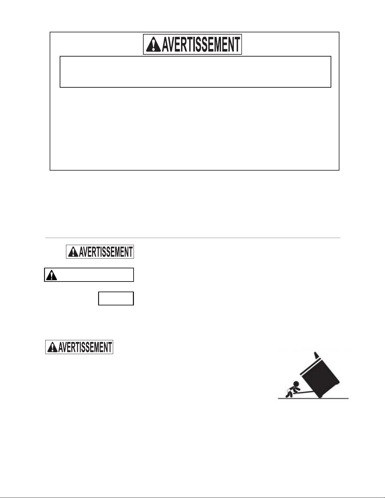
DANGER DE BASCULEMENTDANGER DE BASCULEMENT
Une personne, enfant ou adulte, peut faire basculer la cuisinière et subir des
blessures mortelles.
Vérifiez l’installation du dispositif anti-basculement conformément aux
instructions d’installation.
Ne pas utiliser la cuisinière lorsque le dispositif n’est pas installé et engagé.
Vérifiez l’engagement du dispositif anti-basculement si la cuisinière est déplacée, par exemple quand vous
nettoyez derrière elle.
Pour vérifier l’engagement, inclinez doucement la cuisinière vers l’avant tout en tirant de l’arrière de
l’appareil. La cuisinière ne doit pas bouger de plus de 1 po [2,5 cm].
Le non-respect de ces instructions peut entraîner la mort ou des brûlures graves chez les enfants et les
adultes.
Pour réduire le risque de brûlure, ne déplacez pas cet appareil lorsqu’il est chaud.
LISEZ ATTENTIVEMENT ET COMPLÈTEMENT CES INSTRUCTIONS AVANT
D’INSTALLER OU D’UTILISER VOTRE APPAREIL AFIN DE RÉDUIRE LES
RISQUES D’INCENDIE, DE BRÛLURE OU D’AUTRES BLESSURES. CONSERVER
CE MANUEL POUR RÉFÉRENCE FUTURE.
Ne pas entreposer ou utiliser d’essence ou tout autre liquide ou gaz inflammable à proximité
de cet appareil ou de tout autre appareil.
L ’installation et la réparation doivent être effectuées par un installateur ou une agence
deréparation ayant les qualifications requises.
NE RÉPARER, REMPLACER OU ENLEVER AUCUNE PARTIE DE L’APPAREIL SAUF
RECOMMANDATION SPÉCIFIQUE DANS LE MANUEL. UNE INSTALLATION, UN
SERVICE OU UNE MAINTENANCE INCORRECTS PEUVENT CAUSER DES BLESSURES
OU DES DOMMAGES MATÉRIELS. CONSULTEZ CE MANUEL POUR OBTENIR DES
CONSEILS. TOUTE AUTRE RÉPARATION DOIT ÊTRE EFFECTUÉE PAR UN TECHNICIEN
QUALIFIÉ.
LE NON-RESPECT À LA LETTRE DE CES INSTRUCTIONS PEUT CAUSER
UN INCENDIE OU UNE EXPLOSION, QUI POURRAIT ENTRAÎNER DES
DOMMAGES MATÉRIELS, DES BLESSURES OU LA MORT.
1
FR
©2021 Hestan Commercial Corporation
S’il est bien entretenu, cet appareil Hestan procurera un service sûr et fiable pendant de nombreuses
années. Lorsqu’on se sert de cet appareil, les pratiques élémentaires suivantes en matière de sécurité
doivent être adoptées.
IMPORTANT: Conservez ces instructions à l’intention de l’Inspecteur local des services de l’électricité.
INSTALLATEUR: Veuillez laisser ces instructions d’installation au propriétaire.
PROPRIÉTAIRE: Veuillez conserver ces instructions d’installation pour référence future.
Cette cuisinière N’EST PAS conçue pour être installée dans des maisons préfabriquées (mobiles) ou dans
des véhicules récréatifs. N’installez PAS cette cuisinière à l’extérieur.
PRÉCAUTIONS DE SÉCURITÉ - AVANT DE COMMENCER
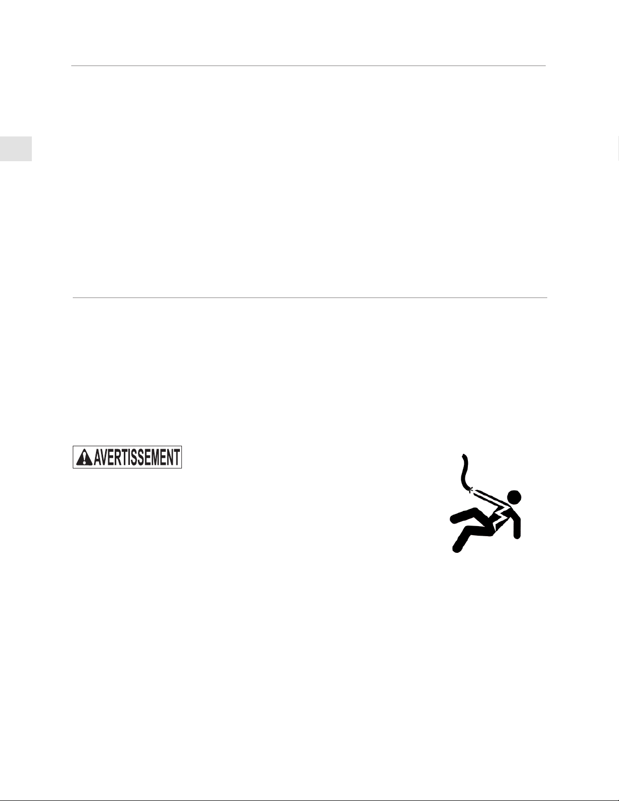
RISQUE DE CHOC ÉLECTRIQUERISQUE DE CHOC ÉLECTRIQUE
Débranchez l’alimentation avant d’installer ou d’entretenir l’appareil. Avant de
le mettre sous tension, assurez-vous que toutes les commandes sont en position
«OFF». Ne pas le faire peut entraîner un choc électrique ou la mort.
MISE À LA TERRE ÉLECTRIQUEMISE À LA TERRE ÉLECTRIQUE
Cet appareil doit être mis à la terre. La mise à la terre réduit le risque de choc
électrique en cas de court-circuit. Lisez la section BRANCHEMENTS ÉLECTRIQUES de ce manuel pour
des instructions complètes.
Cet appareil est pourvu d’une fiche à quatre broches don’t une mise à la terre assurant une protection
contre les chocs électriques. La prise dans laaquelle elle est branchée doit être correctement mise à la
terre. Ne pas couper ni enlever la broche de mise à la terre de la fiche.
ALIMENTATION ÉLECTRIQUEALIMENTATION ÉLECTRIQUE
L’appareil doit avoir son propre circuit distinct - 240 VAC, monophasé, 60 Hz, avec une ampérage
nominale telle qu’indiquée dans la liste des numéros de modèle à la page2. Demandez à l’installateur
de vous montrer où se trouve le disjoncteur électrique afin de savoir comment couper l’alimentation de
cet appareil. Il incombe à l’utilisateur de faire raccorder l’appareil par un électricien agréé conformément
à tous les codes locaux, ou en l’absence de ces codes, conformément au Code National de l’Électricité.
Lisez la section BRANCHEMENTS ÉLECTRIQUES du cet manuel pour tous le détails.
TABLE DES MATIÈRES
1 PRÉCAUTIONS DE SÉCURITÉ - AVANT DE COMMENCER
2 NUMÉROS DE MODÈLE
2 PLAQUE SIGNALÉTIQUE
3 RESPECT DE LA RÉGLEMENTATION ET DES CODES EN VIGUEUR
3 EMPLACEMENT ET INSTALLATION / VENTILATION
9 DOSSERET ET ACCESSOIRES
10 INSTALLATION DU DISPOSITIF ANTI-BASCULEMENT
11 BRANCHEMENTS ÉLECTRIQUES
13 PHASE FINALE DE L’INSTALLATION
14 SERVICE
14
APPENDICE

2
FR
©2021 Hestan Commercial Corporation
NUMÉROS DE MODÈLE
MODÈLES DE CUISINIÈREMODÈLES DE CUISINIÈRE
NO. MODÈLENO. MODÈLE DESCRIPTIONDESCRIPTION
DISJONCTEUR DISJONCTEUR
REQUISREQUIS
KRI30 CUISINIÈRE À INDUCTION AVEC 4 ÉLÉMENTS, 30 po 50 Ampères
KRI36 CUISINIÈRE À INDUCTION AVEC 5 ÉLÉMENTS, 36 po 50 Ampères
KRI36KRI36KRI30KRI30
PLAQUE
SIGNALÉTIQUE
PLAQUE SIGNALÉTIQUE
La plaque signalétique donne des informations importantes sur
cet appareil Hestan telles que les numéros de série et de modèle,
les caractéristiques électriques, et les dégagements minima
d’installation.
La plaque signalétique est située à l’un des deux endroits, comme
indiqué dans les figures de cette page.
Si un entretien est nécessaire, contactez le service clientèle de
Hestan avec les informations sur le modèle et le numéro de série
figurant sur la plaque.
PLAQUE
SIGNALÉTIQUE
Plaque signalétique KRI36 illustréePlaque signalétique KRI36 illustrée

3
FR
©2021 Hestan Commercial Corporation
RESPECT DE LA RÉGLEMENTATION ET DES CODES EN VIGUEUR
L’installation de cet appareil de cuisson doit être effectuée conformément aux codes locaux, ou en
l’absence de tels codes, au National Electrical Code.
Tous les composants électriques doivent mis à la terre conformément aux codes locaux ou, en l’absence de
tels codes, au National Electrical Code ANSI/NFPA 70 ou au Code national de l’électricité du Canada CSA
C22.1.
Cet équipement est conforme à la partie 18 des Règles de la FCC. Cet appareil génère, utilise et peut
émettre de l’énergie sous la forme de fréquence radio et, s’il n’est pas installé et utilisé en conformité avec
les instructions, il peut provoquer des interférences nocives sur les communications radio. Cependant,
il n’existe aucune garantie que des interférences se produiront dans une installation particulière. Si cet
appareil provoque des interférences nocives sur la réception radio ou télévision, ce qui peut être détecté
en mettant l’appareil sous et hors tension, l’utilisateur est encouragé à essayer de corriger ces interférences
en appliquant l’une ou plusieurs des measures suivantes:
• Réorientez ou déplacez l’antenne réceptrice.
• Augmentez la distance entre l’appareil et le récepteur.
• Branchez l’appareil dans une prise ou un circuit différent de celui sur lequel est branché le récepteur.
• Consultez le revendeur ou un technicien radio / TV expérimenté pour obtenir de l’aide.
Les personnes qui ont un stimulateur cardiaque ou d’autres implants électroniques doivent discuter
avec leur médecin ou le fabricant de l’implant pour savoir si cet appareil est suffisamment à l’abri des
interférences.
DÉBALLAGE ET PLACEMENTDÉBALLAGE ET PLACEMENT
Retirez le carton extérieur et les matériaux d’emballage de la palette d’expédition. Ne retirez pas le
film plastique recouvrant les surfaces en acier inoxydable. Ce film protège la finition contre les rayures
jusqu’à ce que l’appareil soit installé dans sa position finale.
Soyez extrêmement prudent avec la surface en verre céramique. Il peut se fissurer ou se briser s’il n’est
pas manipulé avec soin. Déplacez doucement l’unité pour éviter de la faire tomber ou de la secouer
excessivement, ce qui pourrait endommager la verre céramique.
L’unité est très lourde et doit être manipulée avec soin. Utilisez un équipement de sécurité approprié,
tel que des gants, et au moins 2 personnes pour mettre l’appareil en position pour éviter les blessures et
éviter d’endommager le sol ou l’appareil lui-même.
N’UTILISEZ PAS DE CHARIOT À BRAS À L’AVANT OU À L’ARRIÈRE DE LA
CUISINIÈRE. MANIPULER ET DÉPLACER DEPUIS LES CÔTÉS.
Ne soulevez ou ne portez pas l’appareil en le tenant par la porte ou la poignée du four.
Cela pourrait endommager les charnières de la porte.
EMPLACEMENT ET INSTALLATION / VENTILATION
AVIS

4
FR
©2021 Hestan Commercial Corporation
EMPLACEMENT ET INSTALLATION / VENTILATION
(SUITE)
La cuisinière est maintenue sur la palette avec 4 grands boulons d’expédition des deux côtés. Retirez
ces boulons, puis déplacez la cuisinière au sol avec l’aide de 2 personnes.
PRÉPARATIONPRÉPARATION
Avant de déplacer la cuisinière, protégez tout revêtement de sol fini et fermez la(les) porte(s) du four
afin qu’elle(s) ne soi(en)t pas endommagée(s).
DÉGAGEMENTS ET D’APPROVISIONNEMENT ÉLECTRIQUEDÉGAGEMENTS ET D’APPROVISIONNEMENT ÉLECTRIQUE
S’il n’est pas déjà en place, installez la prise de courant / boîte de jonction comme indiqué dans les
dégagements d’installation sur les pages suivantes. Toute ouverture dans le mur ou le sol derrière
l’appareil doit être scellé.
La cuisinière est conçue pour être installée près du mur arrière*. Il peut être nécessaire de
repositionner la réceptacle d’alimentation / boîte de connexion afin d’accommoder la cuisinière
lorsqu’elle est repoussée contre le mur.
La boîte de connexion murale ne doit pas dépasser de plus de 2-3/8 po [6,1 cm] du mur et permettez
toujours que l’arrière de la cuisinière soit presque au même niveau que le mur arrière.
* Sauf si installé dans une île sans mur arrière.
1-5/16 po
[3,3 cm]
CORDON
D’ALIMENTATION
BOÎTE DE CONNEXION
À L’INTÉRIEUR DU MUR
2 po
[5,1 cm]
PRISE ÉLECTRIQUE
NEMA 14-50
BOÎTE DE
CONNEXION
CONDUIT
DE CÂBLAGE
ARMOIRESARMOIRES
Pour éliminer le risque de brûlures ou d’incendie lorsqu’on se penche au-dessus des unités de surface
chauffées, il convient d’éviter d’utiliser l’espace de rangement offert par les armoires situés au-
dessus des unités de surface. Si on doit prévoir un espace de rangement, le risque peut être réduit en
installant la hotte d’évacuation requise de façon à ce qu’elle dépasse horizontalement d’au moins 5 po
[12,7 cm] du fond des armoires.

5
FR
©2021 Hestan Commercial Corporation
EMPLACEMENT ET INSTALLATION / VENTILATION
(SUITE)
RÉINSTALLATION DE LA PORTE DU FOURRÉINSTALLATION DE LA PORTE DU FOUR
1. Tenez fermement la porte des deux côtés (PAS PAR LA POIGNÉE) à environ 30° de la position fermée
et insérez les charnières dans les fentes du four. Le bord inférieur de chaque charnière comporte une
encoche qui doit se loger à l’intérieur de l’ouverture de la fente. NE PAS FORCER, COURBER NI
GAUCHIR LA PORTE! [ E & F ]
2. Ouvrez lentement la porte complètement. Faites pivoter les griffes à charnières à l’opposé de vous
jusqu’à ce qu’elles soient complètement à l’intérieur de l’ouverture de la fente et complètement
insérées. Un tournevis peut vous aider à le faire. [ G ]
3. Rebranchez le connecteur électrique et assurez-vous qu’il est bien fixé à l’intérieur de la porte.
Remettez le petit couvercle en plastique en place. [H ]
4. Fermez doucement la porte du four pour vérifier son bon fonctionnement.
Griffe à
charnière
Couverture
A
Griffe à
charnière
B
C
F
G
H
RETRAIT DE LA PORTE DU FOURRETRAIT DE LA PORTE DU FOUR
Si vous avez une porte très étroite s’ouvrant sur votre cuisine, la(les) porte(s) du four peu(ven)t être
enlevée(s). NE RETIRER QUE SI ABSOLUMENT NÉCESSAIRE. Le retrait de la ou des portes ne doit
être effectué que par un installateur ou un technicien de maintenance agréé. Assurez-vous que le four
est complètement refroidi et que l’alimentation électrique est coupée. Ne pas le faire peut provoquer
un choc électrique ou une brûlure. Faites attention en enlevant la porte, car elle est très lourd. Veillez à
déconnecter le fil à l’intérieur de la porte.
1. Ouvrez la porte du four complètement.
2. Retirez le couvercle près de la charnière pour accéder au connecteur électrique à l’intérieur. À l’aide
d’une petite pince à bec fin et d’un petit tournevis à lame plate, déconnectez les fils à l’intérieur de la
porte. [ A ]
3. À chaque emplacement de charnière, faites pivoter le griffe de charnière vers l’avant jusqu’à ce qu’il
s’arrête. Un tournevis peut être nécessaire pour ce faire. [ B ]
4. Fermez doucement la porte du four jusqu’à ce qu’elle s’arrête contre les griffes à charnières, ou à
environ 30° de la position fermée. Tenez fermement les deux côtés de la porte (pas la poignée) et
tirez la porte droit vers le haut pour la séparer des charnières. Demandez à un assistant de vous aider
à diriger les fils hors du bas de la porte de façon à ce qu’elle ne soit suspendue à rien. Placez la porte
du four dans un endroit sûr jusqu’à ce que vous en ayez besoin. NE JAMAIS relâcher les griffes à
charnières et essayer de fermer les charnières. Cela fermera les charnières avec une grande force, ce
qui pourrait causer des blessures. [ C & D ]

6
FR
©2021 Hestan Commercial Corporation
EMPLACEMENT ET INSTALLATION / VENTILATION
(SUITE)
PLANCHER FINI
2-5/8”
[6,7]
po61/31-03
[78,3]
po61/11-42
[62,7]
13 po [33]
MAX.
DOSSERET
PROFILÉ POUR
ÎLOT MONTRÉ
PROFONDEUR
MAX. DU
RENFONCEMENT
MATÉRIAUX
COMBUSTIBLES
36-7/8 - 38-3/8 po
[93,7 - 97,5]
À LA SURFACE
DE CUISSON
48-5/16 po
3 po
[7,6]
EMPLACEMENT DE
L'ALIMENTATION
DE L’ÉLECTRICITÉ
SUR LE PLANCHER.
LES DIMENSIONS ENTRE CROCHETS [ ]
SON EN CM.
[122,7]
FIN DE LA
POIGNÉE
DÉGAGEMENTS D'INSTALLATION - TOUS LES DOSSERETS
VUE DE CÔTÉ
5-7/8 po
[14,9]
HAUT DE
L'APPAREIL
/
SURFACE DE
CUISSON
HOTTE
NIVELLEMENTNIVELLEMENT
La cuisinière doit être de niveau. Soulevez ou abaissez la cuisinière à la hauteur désirée en ajustant les
quatre pieds de mise de niveau sous la cuisinière. Les pieds peuvent être tournées à la main. Il peut être
nécessaire d’utiliser un levier ou un autre dispositif de levage pour aider à soulever temporairement l’unité
pour tourner les pieds. Ne pas soulever ou tirer le levier depuis l’avant ou l’arrière, uniquement depuis les
côtés.
PRÉCAUTION
Le dessus de l’appareil
doit être au même niveau
ou plus haut que les
surfaces des plans de
travail contigus. Le fait de
ne pas ajuster la hauteur
peut exposer les armoires
contigus à une chaleur
excessive qui pourrait
endommager les armoires
ou le plan de travail.

7
FR
©2021 Hestan Commercial Corporation
EMPLACEMENT ET INSTALLATION / VENTILATION
(SUITE)
E
W
V
DÉGAGEMENTS D'INSTALLATION
30
PO - TOUS LES DOSSERETS
VUE DE FACE
COMPTOIR
FACE DU TIROIR
RECOUVERTE
FACE DU PORTE
RECOUVERTE
1
8
po
[3,2 mm]
LES DIMENSIONS
ENTRE CROCHETS
[ ] SON EN CM.
18 po [45,7]
MIN.
11 po
[27,9]
7 po
[17,8]
[6,4]
2-1/2 po
PLANCHER
FINI
ALIMENTATION ÉLECTRIQUE
HOTTE DE VENTILATION
MATÉRIAUX
COMBUSTIBLES
DÉGAGEMENT ZÉRO
PERMIS À LA SURFACE
LATÉRALE COMBUSTIBLE
LA PLUS PROCHE
REMARQUES:
• LES ZONES OMBRÉES INDIQUENT LES ENDROITS OÙ LES MATÉRIAUX COMBUSTIBLES SON PROHIBÉS.
• LE DESSUS DE L’APPAREIL DOIT ÊTRE AU MÉME NIVEAU OU PLUS HAUT QUE LES SURFACES DES PLANS DE
TRAVAIL CONTIGUS.
• «E» EST LA ZONE D’ALIMENTATION ÉLECTRIQUE.
• «W» INDIQUE L’OUVERTURE DESTINÉE À L’APPAREIL.
REMARQUE: LA FIN DE LA POIGNÉE S’ÉTEND DE 1/8 PO [3,2 mm] AU-DELÀ DE CHAQUE CÔTÉ DE L’APPAREIL.
IL PEUT ÊTRE NÉCESSAIRE DE FOURNIR UNE ADAPTATION À DES TIROIRS OU DES ARMOIRES ADJACENTS.
• «V» INDIQUE LE DÉGAGEMENT MIN. PAR RAPPORT À LA HOTTE DE VENTILATION.
MODÈLE DE
CUISINIÈRE
W
V (MIN)
KRI30 30 po [76,2] 30 po [76,2]

8
FR
©2021 Hestan Commercial Corporation
EMPLACEMENT ET INSTALLATION / VENTILATION
(SUITE)
W
V
E
PLANCHER
FINI
LES DIMENSIONS
ENTRE CROCHETS [ ]
SON EN CM.
6 po
[15,2]
2-1/2 po
[6,4]
5 po
[12,7]
ALIMENTATION
ÉLECTRIQUE
19 po
[48,3]
9-1/2 po
[24,1]
18 po
HOTTE DE VENTILATION
[45,7]
MATÉRIAUX
COMBUSTIBLES
VUE DE FACE
DÉGAGEMENTS D'INSTALLATION 36 PO - TOUS LES DOSSERETS
COMPTOIR
FACE DU TIROIR
RECOUVERTE
FACE DU PORTE
RECOUVERTE
1
8
po
[3,2 mm]
DÉGAGEMENT ZÉRO
PERMIS À LA SURFACE
LATÉRALE COMBUSTIBLE
LA PLUS PROCHE
MODÈLE DE
CUISINIÈRE
W
V (MIN)
KRI36 36 po [91,4] 30 po [76,2]
REMARQUES:
• LES ZONES OMBRÉES INDIQUENT LES ENDROITS OÙ LES MATÉRIAUX COMBUSTIBLES SON PROHIBÉS.
• LE DESSUS DE L’APPAREIL DOIT ÊTRE AU MÉME NIVEAU OU PLUS HAUT QUE LES SURFACES DES PLANS DE
TRAVAIL CONTIGUS.
• «E» EST LA ZONE D’ALIMENTATION ÉLECTRIQUE.
• «W» INDIQUE L’OUVERTURE DESTINÉE À L’APPAREIL.
REMARQUE: LA FIN DE LA POIGNÉE S’ÉTEND DE 1/8 PO [3,2 mm] AU-DELÀ DE CHAQUE CÔTÉ DE L’APPAREIL.
IL PEUT ÊTRE NÉCESSAIRE DE FOURNIR UNE ADAPTATION À DES TIROIRS OU DES ARMOIRES ADJACENTS.
• «V» INDIQUE LE DÉGAGEMENT MIN. PAR RAPPORT À LA HOTTE DE VENTILATION.

9
FR
©2021 Hestan Commercial Corporation
EMPLACEMENT ET INSTALLATION / VENTILATION
(SUITE)
EXIGENCES DE VENTILATIONEXIGENCES DE VENTILATION
Il est fortement recommandé d’installer cet appareil avec une hotte Hestan. Bien que cet appareil n’ait
pas la puissance thermique élevée d’une cuisinière à gaz traditionnelle, l’évacuation de la vapeur (d’eau),
des vapeurs et des odeurs de cuisson est toujours souhaitable. Il est très important que l’installation de la
hotte et des conduits réponde aux codes de construction locaux et soit réalisée par un technicien qualifié.
N’utilisez pas de système de ventilation à tirage descendant.
Ne montez pas un ensemble four à micro-ondes / ventilateur au-dessus de la cuisinière. Ces types d’unités
n’offrent pas un débit d’air suffisant et n’ont pas été testés avec ce type d’appareil.
Pour les hottes de ventilation non approuvées par Hestan, la hotte de ventilation et /ou le souffleur
doivent être évalués à au moins 300 CFM [510 m³/h] pour des tailles de cuisinière à induction de 30 et 36
po.
Pour les applications en îlot, il est recommandé d’utiliser une hotte d’évacuation plus large de 6 po [15,2
cm] que l’appareil, pour permettre un chevauchement de 3 po [7,6 cm] à gauche et à droite de l’appareil.
Gardez le conduit court aussi court et droit que possible. Les coudes et les raccords de transition
réduisent l’efficacité du flux d’air. Hestan recommande de maintenir la longueur du conduit à moins de 50
pieds [15,2 m].
CONSULTEZ VOTRE CONCESSIONNAIRE HESTAN POUR CHOISIR LA HOTTE
DE VENTILATION APPROPRIÉ POUR VOTRE APPAREIL HESTAN.
DOSSERET ET ACCESSOIRES
Les accessoires en tôle tels que le dosseret et les zones à l’arrière de la cuisinière peuvent avoir des bords
tranchants. Portez des gants de travail pendant la manipulation et l’installation de ces articles.
DOSSERETDOSSERET
Votre cuisinière Hestan est fournie en usine avec un dosseret Island Trim (à Profilé pour Îlot). Voir le
Tableau 1 de la section APPENDICE de ce manuel pour d’autres options de dosseret disponibles chez
votre concessionnaire Hestan. La sélection du dosseret approprié dépend du lieu d’installation et des
matériaux contigus, ainsi que du type de hotte à utiliser. Les instructions d’installation accompagnent le
kit de dosseret.
Le haut du dosseret sert d’échappement pour le four pendant le fonctionnement et comme évent pour
évacuer la chaleur de la partie supérieure de la cuisinière. NE PAS BLOQUER ou obstruer le haut du
dosseret. NE PAS touchez le haut du dosseret pendant le fonctionnement de l’appareil, car il pourrait
chauffer. Lui laisser suffisamment de temps pour refroidir avant de toucher ou de nettoyer cette zone.
NE PAS placer à proximité d’objets en plastique ou d’autres objets sensibles à la chaleur qui pourraient
fondre ou brûler.
PRÉCAUTION
PRÉCAUTION

10
FR
©2021 Hestan Commercial Corporation
INSTALLATION DU DISPOSITIF ANTI-BASCULEMENT
LE DISPOSITIF ANTI-BASCULEMENT FOURNI AVEC
CETTE CUISINIÈRE DOIT ÊTRE INSTALLÉ.
PRÉPARATIONPRÉPARATION
AVIS
DÉGÂTS MATÉRIELS POSSIBLES - Faites appel à un installateur ou à un entrepreneur
qualifié pour déterminer la méthode appropriée de fixation du support anti-basculement
sur le mur arrière ou le plancher derrière votre cuisinière. Des perceuses ou des outils spéciaux peuvent
être nécessaires pour percer des trous dans le mur ou le plancher (carreaux de céramique, planchers de
bois dur, etc.).
RISQUE DE CHOC ÉLECTRIQUE - Faites preuve d’une extrême prudence
lorsque vous percez des trous dans le mur ou le plancher, car il pourrait y avoir
des fils cachés. Identifier les circuits électriques qui pourraient être affectés par
l’installation du support anti-basculement. Coupez l’alimentation de ces circuits. Le non-respect de ces
instructions peut entraîner la mort ou un choc électrique.
PRÉPARATION DES TROUSPRÉPARATION DES TROUS
Le support anti-basculement doit être installé dans des matériaux solides, tels que des colombage en bois
dans le mur ET des solives de plancher sous le plancher fini. Ils doivent être capables de résister aux forces
exercées sur le support par la cuisinière si celle-ci bascule. Si des colombage en bois ou d’autres matériaux
appropriés ne se trouvent pas dans la zone désignée derrière la cuisinière, vous devez fixer le support à
l’aide d’ancrages pour placoplâtre appropriés ou d’attaches similaires.
INSTALLATION DEVANT DU PLACOPLÂTRE: Après avoir positionné le support conformément au
schéma ci-dessous, marquez les trous et percez les trous appropriés conformément aux instructions
fournies avec les ancrages muraux. Pour le panneau isorel ou en plâtre massif, vous aurez peut-être besoin
de différentes chevilles, disponibles dans votre quincaillerie ou magasin de bricolage locale.
INSTALLATION SUR PLANCHER DE BOIS: Après avoir positionné le support comme indiqué sur le
schéma ci-dessous, marquer les trous et percer les trous appropriés pour les grandes vis à bois n°12 ou
similaires, d’au moins 1,5 po [3,8 cm] de longueur. Utilisez également des rondelles. Tout le matériel est
disponible dans votre quincaillerie ou magasin de bricolage locale.
INSTALLATION SUR PLANCHER DE BÉTON: Après avoir positionné le support comme indiqué sur le
schéma ci-dessous, marquer les trous et percer les trous appropriés pour les gros ancrages de maçonnerie
n°12 ou similaires, d’au moins 1,5 po [3,8 cm] de longueur. Utilisez également des rondelles. Tout le
matériel est disponible dans votre quincaillerie ou magasin de
bricolage locale.
X
MODÈLE DE CUISINIÈRE
X
KRI30, KRI36 1-1/16 po [2,7]

11
FR
©2021 Hestan Commercial Corporation
INSTALLATION DU DISPOSITIF ANTI-BASCULEMENT
(SUITE)
AJUSTEMENT DU BOULON ANTI-BASCULEMENTAJUSTEMENT DU BOULON ANTI-BASCULEMENT
Après avoir mis à niveau la cuisinière, et
après avoir fixé le support, réglez le boulon
anti-basculement et la grosse rondelle sous
la cuisinière de façon à ce que le dessus de la
rondelle soit à 1-1/4 po [3,2 cm] au maximum
du plancher. Faites glisser la cuisinière dans
l’ouverture du support et vérifiez que le
boulon est engagé dans le support comme
indiqué ci-dessous. Faites délicatement
basculer la cuisinière vers l’avant pour vérifier.
La cuisinière ne doit pas bouger de plus de 1
po [2,5 cm].
BRANCHEMENTS ÉLECTRIQUES
RISQUE DE CHOC ÉLECTRIQUERISQUE DE CHOC ÉLECTRIQUE
Débranchez l’alimentation avant d’installer ou d’entretenir l’appareil. Avant de
mettre l’appareil sous tension, assurez-vous que toutes les commandes sont en
position «OFF». Ne pas le faire peut entraîner un choc électrique ou la mort.
MISE À LA TERRE ÉLECTRIQUEMISE À LA TERRE ÉLECTRIQUE
Cet appareil doit être mis à la terre. La mise à la terre réduit le risque de choc
électrique en cas de court-circuit. La mise à la terre par le conducteur neutre est interdite pour les
nouvelles installations de circuit de dérivation (1996 NEC), ainsi dans les maisons mobiles et les véhicules
récréatifs, ou dans une zone où les codes locaux l’interdisent. Cette cuisinière a été configurée à l’usine
pour un branchement à 4 fils.
PRÉCAUTION
Une mise à la terre incorrecte entraînera des dysfonctionnements dans
l’unité, tels que des étincelles continues des allumeurs. Cela peut
endommager l’appareil et créer une situation d’électrocution.
BRANCHEMENT ÉLECTRIQUEBRANCHEMENT ÉLECTRIQUE
L’appareil peut être connecté à l’aide du cordon fourni ou par un câblage fixe. L’appareil doit avoir son
propre circuit distinct - 240 VAC, monophasé, 60 Hz, avec un ampérage comme indiqué dans la liste des
numéros de modèle à la page2. L’installation doit être effectuée conformément aux codes locaux, ou
en l’absence de codes locaux, elle doit être installée conformément au Code National de l’Électricité, ANSI
/ NFPA 70.
Pour les installations aux États-Unis et au Canada: Cet appareil est équipé de
fils de cuivre et il doit être connecté uniquement à des fils de cuivre. Une
connexion inadéquate du câble electrique en aluminium peut entraîner un
risque d’incendie ou d’électrocution. Utilisez uniquement des connecteurs
conçus et certifiés pour la connexion au fil d’aluminium et installés par un
électricien qualifié.

12
FR
©2021 Hestan Commercial Corporation
BRANCHEMENTS ÉLECTRIQUES
(SUITE)
POUR UNE CONNEXION À 3 FILSPOUR UNE CONNEXION À 3 FILS
Pour les installations où de faire la mise à la terre via
le conducteur neutre est autorisée. N’utilisez que des
kits de cordon à 3 conducteurs de 125/250 volts (min),
50 ampères et étiquetés «Conçue pour les Cuisinières».
Ce cordon est disponible dans les quincailleries et les
magasins de bricolage.
1. Assurez-vous que le panneau d’alimentation /
disjoncteur est hors tension.
2. Retirez le panneau d’accès étroit à l’arrière de la
cuisinière et repérez la borne du châssis. Raccorder
le fil VERT de mise à la terre de l’appareil et le
fil neutre BLANC au fil neutre BLANC du boîter
électrique.
3. Raccorder le fil ROUGE (L1) de l’appareil au fil
d’alimentation ROUGE du boîter électrique.
4. Raccorder le fil NOIR (L2) de l’appareil au fil
d’alimentation NOIR du boîter électrique.
5. Resserrer tous les raccordements. Le bride de
cordon doit être installée.
POUR UNE CONNEXION À 4 FILSPOUR UNE CONNEXION À 4 FILS
Pour les installations où de faire la mise à la terre via le
conducteur neutre est prohibée. N’utilisez que des kits
de cordon à 4 conducteurs pour 125/250 volts (min),
50 ampères et étiquetés «Conçue pour les Cuisinières».
Votre cuisinière Hestan est pré-câblée à l’usine pour une
connexion à 4 fils et est dotée de ce cordon.
1. Assurez-vous que le panneau d’alimentation /
disjoncteur est hors tension.
2. Retirez le panneau d’accès étroit à l’arrière de la
cuisinière et repérez la borne du châssis. Raccorder
le fil VERT de mise à la terre de l’appareil du circuit
d’alimentation ou du cordon au châssis à l’aide de la
vis de terre.
3. Raccorder le fil neutre BLANC de l’appareil au fil
neutre BLANC du boîter électrique.
4. Raccorder le fil ROUGE (L1) de l’appareil au fil
d’alimentation ROUGE du boîter électrique.
5. Raccorder le fil NOIR (L2) de l’appareil au fil
d’alimentation NOIR du boîter électrique.
6. Resserrer tous les raccordements. Le bride de
cordon doit être installée.
STRAIN RELIEF /
BRIDE DE CORDON
POWER CORD /
CORDON D’ALIMENTATION
GROUND TERMINAL /
BLOC DE MISE
À LA TERRE
STRAIN RELIEF /
BRIDE DE CORDON
POWER CORD /
CORDON D’ALIMNENTATION
GROUND TERMINAL /
BLOC DE MISE
À LA TERRE
JUMPER WIRE /
FIL CONNECTEUR

13
FR
©2021 Hestan Commercial Corporation
PHASE FINALE DE L’INSTALLATION
Retirez tous les matériaux d’emballage final et le film protecteur de toutes les zones extérieures. Vérifiez
l’intérieur du four pour d’autres articles d’emballage, du ruban adhésif sur les grilles du four, etc.
Avant de tester le fonctionnement de l’appareil, vérifiez que l’alimentation électrique a été rétablie dans
l’unité.
Toutes les boutons de commande doivent être en position «OFF» pour éviter une mise en marche
intempestive lors de la mise sous tension. Pour assurer la sécurité du client en cas de panne de courant, le
cuisinière affichera un message d’erreur lorsque l’alimentation est rétablie, à moins que tous les boutons
ne soient en position «OFF». Réglez tous les boutons sur «OFF» et réarmez le disjoncteur pour effacer le
message d’erreur.
N’ESSAYEZ PAS D’UTILISER LA CUISINIÈRE PENDANT UNE PANNE DE COURANT PROLONGÉE.
ESSAI FONCTIONNELESSAI FONCTIONNEL
1. Remplir un ustensile de cuisson à induction avec 1/2 - 1 po [1.2-2.5 cm] d’eau et le placer sur l’une des
zones de cuisson.
2. Allumez la commande en appuyant sur la touche [ON OFF] (1).
• Si les commandes sont verrouillées, appuyez sur le bouton de verrouillage (10) pendant quelques
secondes. Le verrou est désactivé et les commandes doivent répondre.
3. Appuyez sur la touche de sélection de zone (5) pour la zone de cuisson où se trouve l’ustensile de
cuisson.
4. Appuyez sur le curseur d’alimentation de cette zone et réglez-le sur un niveau compris entre 3 et 9.
5. Observez que l’affichage répond au réglage de puissance et observez que la ustensile de cuisson
commence à chauffer.
6. Appuyez sur la touche de sélection (5) de cette zone pour l’éteindre.
7. Appuyez sur la touche [ON OFF] pour éteindre la table de cuisson.
INTERFACE UTILASATEUR
1 ON/OFF (Marche / Arrêt) 7
Indicateur de l'horloge de la minuterie
(pour chaque zone)
2 Curseur d’alimentation - puissance minimale 8 Point indicateur de sélection
3 Curseur d’alimentation - puissance maximale 9 Fonction de pause / rappel
4 BOOSTER (amplificateur) de Puissance (P) 10 Fonction de verrouillage des touches
5 Affichages de la zone de cuisson 11 Fonction Chef Cook
6
Affichage de la minuterie et touches de
réglage + / -
12 Fonction de Réchauffement
CRITERIACRITERIA
Si les commandes répondent comme décrit et si l’ustensile chauffe, le test est réussi.
AVIS
2 53 4 1
9 10 11 12 6 7 8
14
FR
©2021 Hestan Commercial Corporation
SERVICE
Toutes les réparations sous garantie et hors garantie doivent être effectuées par un technicien qualifié.
Pour trouver un réparateur agrée dans votre région, contactez votre concessionnaire Hestan, votre
représentant local, ou Hestan. Avant d’appeler, veuillez avoir sous la main le numéro de modèle et le
numéro de série.
Hestan Commercial Corporation
3375 E. La Palma Avenue
Anaheim, CA 92806
(888) 905-7463
APPENDICE
TABLEAU TABLEAU 11 - OPTIONS DU DOSSERET - OPTIONS DU DOSSERET
MODÈLE DE MODÈLE DE
CUISINIÈRECUISINIÈRE
MODÈLE DE DOSSERETMODÈLE DE DOSSERET DESCRIPTIONDESCRIPTION
KRI30 KBGIT30* DOSSERET, PROFILE POUR ÎLOT, 30 PO
KBGLB30 DOSSERET, ARRIÈRE BAS, 30 PO
KBGHS30 DOSSERET, ÉTAGÈRE HAUTE , 30 PO
KRI36 KBGIT36* DOSSERET, PROFILE POUR ÎLOT, 36 PO
KBGLB36 DOSSERET, ARRIÈRE BAS, 36 PO
KBGHS36 DOSSERET, ÉTAGÈRE HAUTE , 36 PO
* INCLUS AVEC LA CUISINIÉRE

Hestan Commercial Corporation
3375 E. La Palma Ave
Anaheim, CA 92806
(888) 905-7463
RETAIN THIS MANUAL FOR FUTURE REFERENCE
CONSERVEZ CE MANUEL POUR UNE RÉFÉRENCE FUTURE
©2021 Hestan Commercial Corporation P/N 034583 REV A