
DIi3JTAL TELEViSiONS '_
[]
,ViewPoinl
ON-SCRE N OPERATING SYSTEM
r®
HIGH DEFINITION MULTIMEDIA INTERFACE
TM
TV Unformation:
Use this space to record the model and seriat numbers of
your television, This information is on the back of your TV,
Model number
Serial number
RISK OF ELECTRIC SHOCK
DO NOT OPEN
CAUTION: TO REDUCE THE RiSK OF ELECTRIC SHOCK, DO NOT REMOVE COVER (OR BACK),
NO USER SERVICEABLE PARTS INSIDE REFER SERVICING TO QUALIFIED SERVICE PERSONNEL.
The exclamation point within an equilateral triangle is intended to alert the user to the presence of important
operating and maintenance (servicing) instructions in the literature accompanying the appliance.
Exercise extreme care when lifting or moving this TV. A minimum of two adults should lift or move the TV.
Portions of the advanced circuitry of this TV will sometimes operate while the TV is turned off. This allows the TV to
download guide information and CableCARD TM updates. A cooling fan may switch on during these standby periods
and may be heard in a quiet environment. This is normal operation. Also, the main cooling fan will operate at all times
while the TV is turned on and during the lamp cool-down period just after turning off the TV (approximately one minute).
This is also normal operation.
Custom cabinet installation must allow for proper air circulation around the television.
STAND REQUIREMENT
CAUTION: Mitsubishi TV models WD-52527 and WD-52528 are for use only with Mitsubishi stand models MB-52527 or
MB-52528. Mitsubishi TV models WD-62527 and WD-62528 are for use only with Mitsubishi stand models
MB-62527 or MB-62528_ Use with other stands is capable of resulting in instability causing possible injury.
LAMP REPLACEMENT
The image on this TV is produced by a high-brightness lamp that will operate for many hours. Eventually, however, this
lamp will need to be replaced. It is designed to be easily replaced by the TV owner. Front panel indicators and/or on-
screen messages will assist you in determining when the lamp needs to be replaced. Please see Appendix H for details
on lamp replacement.
To order a new lamp:
While Under Warranty
Call (800) 332-2119. Please have model number, serial
number, and TV purchase date available.
After Warranty 1
Call (800) 553-7278. Order lamp part number
915P028010.
WARNING: TO REDUCE THE RISK OF FIRE OR ELECTRIC SHOCK, DO NOT EXPOSE THIS APPLIANCE TO RAIN OR
MOISTURE.
CAUTION: TO PREVENT ELECTRIC SHOCK, MATCH WIDE BLADE OF PLUG TO WIDE SLOT, FULLY INSERT.
NOTE TO CATV SYSTEM INSTALLER: THIS REMINDER IS PROVIDED TO CALL THE CATV SYSTEM INSTALLER'S
ATTENTION TO ARTICLE 820-40 OF THE NEC THAT PROVIDES GUIDELINES FOR THE PROPER GROUNDING AND,
IN PARTICULAR, SPECIFIES THAT THE CABLE GROUND SHALL BE CONNECTED TO THE GROUNDING SYSTEM OF
THE BUILDING, AS CLOSE TO THE POINT OF CABLE ENTRY AS PRACTICAL.
Note:Thisequipmenthasbeentestedandfoundto compiywiththeiimitsfora CiassBdigitaidevice,pursuantto
part15oftheFCCRubs.Theseiimitsaredesignedto providereasonabbprotectionagainstharmfuiinterference
inaresidentiaiinstallation.Thisequipmentgenerates,usesandcanradiateradiofrequencyenergyand,if not
installedandusedinaccordancewiththeinstructions,maycauseharmfuiinterferenceto radiocommunications.
However,thereisnoguaranteethatinterferencewiiinotoccurinaparticularinstallation.Ifthisequipmentdoes
causeharmfulinterferenceto radioortelevisionreception,whichcanbedeterminedbyturningthe equipmentoff
andon,theuserisencouragedtotry to correcttheinterferencebyoneormoreofthefollowingmeasures:
+ Reorient or relocate the receiving antenna+
+ Increase the separation between the equipment and the receiver+
+ Connect the equipment into an outlet on a circuit different from that to which the receiver is connected+
+ Consult the dealer or an experienced radio/TV technician for help+
Changes or modifications not expressly approved by lViitsubishi could cause harmful interference and would
void the user's authority to operate this equipment.
Note: The digital television is capable of receiving analog basic, digital basic and digital premium cable television
programming by direct connection to a cable system providing such programming. A security card (CabieCARD)
provided by your cable operator is required to view encrypted digital programming. Certain advanced and interactive
digital cable services such as video-on+demand, a cable operator's enhanced program guide and data-enhanced
television services may require the use of a set-top box+ For more information call your local cable operator+
WARNING: This product contains chemicals known to the State of California to cause cancer and/or birth defects or
other reproductive harm+
IIV]PORTANT SAFEG UARDS
PUease read the following safeguards for your TV and retain for future reference.
warnings and instructions marked on the teUevision.
AUways follow aH
1.
2.
3.
4.
5.
Read, Retain and Follow All instructions
Read aH safety and operating instructions before operating the TV. Retain the safety and operating instructions
for future reference. Follow aHoperating and use instructions.
Heed Warnings
Adhere to aH warnings on the appHiance and in the operating instructions.
Cleaning
UnpHug the TV from the wall outlet before cHeaning. Do not use Hiquid, abrasive or aerosoH cleaners. Cleaners can
permanently damage the cabinet and screen. Use a lightly dampened cloth for cleaning.
Attachments and Equipment
Never add any attachments and/or equipment without approval of the manufacturer as such additions may result
in the risk of fire, electric shock or other 3ersonal injury.
Water and Moisture
Do not use the TV where contact with or ummersion in water is possible. Do not use near bath tubs, wash bowls,
kitchen sinks, laundry tubs, swimming pools, etc.
6. Accessories
Do not place the TV on an unstable cart, stand, tripod, or table. The TV may fall, causing seri-
ous injury to a child or adult and serious damage to the TV. Use only with a cart, stand, tripod,
bracket or table recommended by the manufacturer, or sold with the TV. Any mounting of
the TV should follow the manufacturer's instructions, and should use mounting accessories
recommended by the manufacturer.
An appliance and cart combination should be moved with care. Quick stops, excessive force,
and uneven surfaces may cause the appliance and cart combination to overturn.
7.
Ventilation
Slots and openings in the cabinet are provided for ventilation and to ensure reliable operation of the TV and to
protect it from overheating. Do not block these openings or allow them to be obstructed by placing the TV on a
bed, sofa, rug, or other similar surface. Nor should it be placed over a radiator or heat register. If the TV is to be
placed in a rack or bookcase, ensure that there is adequate ventilation and that the manufacturer's instructions
have been adhered to.
6.
g.
10.
11.
Power Source
This TV should be operated only from the type of power source indicated on the marking label. If you are not sure
of the type of power supplied to your home, consult your appliance dealer or local power company.
Grounding or Polarization
This TV is equipped with a polarized alternating current line plug having one blade wider than the other. This plug
will fit into the power outlet only one way. If you are unable to insert the plug fully into the outlet, try reversing the
plug. If the plug should still fail to fit, contact your electrician to replace your obsolete outlet. Do not defeat the
safety purpose of the polarized plug.
Power-Cord Protection
Power-supply cords should be routed so that they are not likely to be walked on or pinched by items placed
upon or against them, paying particular attention to cords at plugs, convenience receptacles, and the point
where they exit from the TV.
Lightning
For added protection for this TV during a lightning storm, or when it is left unattended and unused for long
period of time, unplug it from the wall outlet and disconnect the antenna or cable system. This will prevent
damage to the TV due to lightning and power-line surges.
4
IMPORTANT SAFEGUARDS, continued
12.
13.
14.
15.
16.
17.
18.
19.
20.
Power Lines
An outside antenna system shouHd not be located in the vicinity of overhead power Hinesor other eHectric Hight or
power circuits, or where it can fan into such power Hinesor circuits. When instafling an outside antenna system,
extreme care shouHd be taken to keep from touching such power Hinesor circuits as contact with them might be
fatal
Overloading
Do not overHoad wan outlets and extension cords as this can resuHt in a risk of fire or eHectric shock.
Object and Liquid Entry
Never push objects of any kind into this TV through openings as they may touch dangerous voHtage points or short-
out parts that could result in fire or electric shock. Never spill liquid of any kind on or into the TV.
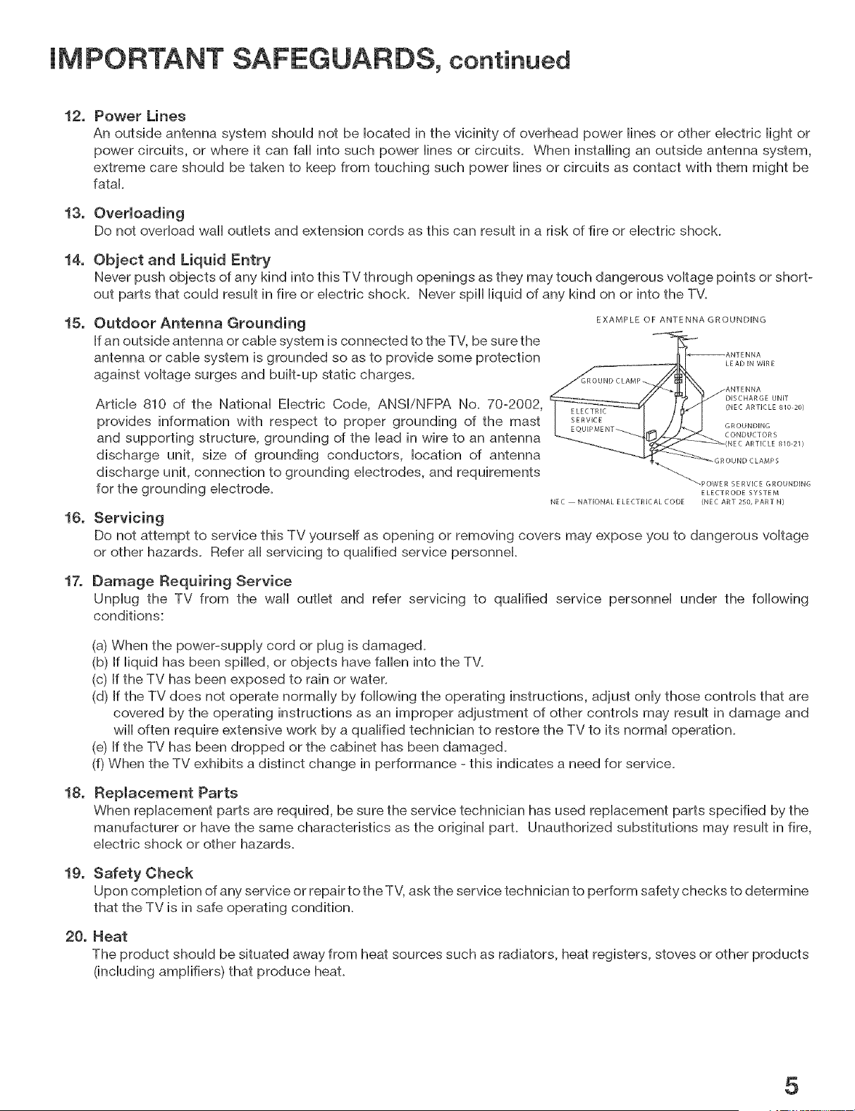
Outdoor Antenna Grounding
If an outside antenna or cable system is connected to the TV, be sure the
antenna or cable system is grounded so as to provide some protection
against voltage surges and built-up static charges.
EXAMPLE OF ANTENNA GROUNDING
LEAD IN WiRE
Article 810 of the National Electric Code, ANSI/NFPA No. 70-2002,
provides information with respect to proper grounding of the mast
and supporting structure, grounding of the lead in wire to an antenna
discharge unit, size of grounding conductors, location of antenna
discharge unit, connection to grounding electrodes, and requirements
for the grounding electrode.
Servicing
DISC HAR GE UNIT
(NEC ARTICLE 810 20)
GROUNDING
CONDUCTORS
NEC ARTICLE 810 21)
-GROUND CLAMPS
_'-POWER SERVICE GROUNDING
ELECTRODE SYSTEM
NEC NATIONAL E LECTR]CAL CODE (NEC ART 250, PART H}
Do not attempt to service this TV yourself as opening or removing covers may expose you to dangerous voltage
or other hazards. Refer all servicing to qualified service personnel.
Damage Requiring Service
Unplug the TV from the wall outlet and refer servicing to qualified service personnel under the following
conditions:
(a) When the power-supply cord or plug is damaged.
(b) If liquid has been spilled, or objects have fallen into the TV.
(c) If the TV has been exposed to rain or water.
(d) If the TV does not operate normally by following the operating instructions, adjust only those controls that are
covered by the operating instructions as an improper adjustment of other controls may result in damage and
will often require extensive work by a qualified technician to restore the TV to its normal operation.
(e) If the TV has been dropped or the cabinet has been damaged.
(f) When the TV exhibits a distinct change in performance - this indicates a need for service.
Replacement Parts
When replacement parts are required, be sure the service technician has used replacement parts specified by the
manufacturer or have the same characteristics as the original part. Unauthorized substitutions may result in fire,
electric shock or other hazards.
Safety Check
Upon completion of any service or repair to the TV, ask the service technician to perform safety checks to determine
that the TV is in safe operating condition.
Heat
The product should be situated away from heat sources such as radiators, heat registers, stoves or other products
(including amplifiers) that produce heat.
5
Chapter 1: Television Overview
Special Features ........................................................................................................... 10
TV Accessories ............................................................................................................. 11
Remote Control Functions: Overview ........................................................................... 12
Remote Control Functions:
Operation ................................................................................................................. 13
Care ......................................................................................................................... 14
Sleep Timer ............................................................................................................. 14
Front Control Panel ...................................................................................................... 15
Front Panel Indicator Lights .......................................................................................... 16
Back Panel ................................................................................................................... 18
Chapter 2: Connecting
External Devices & NetCommand® Setup ................................................................... 22
Wall Outlet Cable or Cable Box .................................................................................... 23
CableCARD TM Technology ........................................................................................... 24
Antenna with Single Lead ............................................................................................. 25
Antennas with Separate UHF and VHF Leads ............................................................. 25
VCR to an Antenna or Wall Outlet Cable ...................................................................... 26
VCR Video and Audio to TV ......................................................................................... 26
VCR Video and Audio to a Cable Box .......................................................................... 27
AiV Receiver ................................................................................................................ 28
Satellite Receiver or Other Device with S-Video .......................................................... 28
DVD Player with Component Video .............................................................................. 29
HDTV Cable Box or Satellite Receiver with Component Video .................................... 29
HDMR Device ................................................................................................................ 30
DVRDevice .................................................................................................................... 30
RREmitter NetCommand® ........................................................................................... 31
Com pati ble IEEE 1394 Devices .................................................................................... 32
Helpful Hints ................................................................................................................. 34
Chapter 3: NetOommand ® Setup and Editing
NetCommand® Introduction ....................................................................................... 36
Using the Remote Control with NetCommand® ......................................................... 37
NetCommand® Setup On-Screen Buttons .................................................................. 38
3D Graphical Viewpoint® Menu System ...................................................................... 39
NetCommand® Initial Setup ........................................................................................ 40
Edit NetCommand®
Add an A/V Receiver .............................................................................................. 43
Add Devices ........................................................................................................... 46
Change Devices ..................................................................................................... 50
Delete Devices ........................................................................................................ 50
Finish Screen .......................................................................................................... 50
Chapter 4 : [EEE 1394 Devices and NetCommand®
Controlled Recordings
REEE 1394 Devices and NetCommand® ControU ......................................................... 52
Adding REEE1394 Devices Automatically ..................................................................... 53
Device SeUection Menu ................................................................................................. 55
Using the Device Menu Button to Display Menus ........................................................ 56
Using the GURDE Button to DispUay ChanneMew TM and Menus .................................. 57
NetCommand® Controlled Peer-to-Peer Connections ................................................ 58
Direct VCR Recording from an Antenna or CaMe Source ............................................ 59
A/V Disc Search ........................................................................................................... 59
Track List Screen ......................................................................................................... 59
Chapter 5: TV Menu Screen Operations
Main Menu Choices ..................................................................................................... 32
Setup Menu .................................................................................................................. 33
NetCommand® Menu .................................................................................................. 35
Record Menu ................................................................................................................ 36
ChanneU Menu .............................................................................................................. 38
SuperQuickView TM ........................................................................................................ 39
Captions Menu ............................................................................................................. 70
V-Chip Lock Menu ........................................................................................................ 72
Audio/Video Menu ........................................................................................................ 75
AiV Settings Descriptions ............................................................................................ 76
Operation of PIP and POP ............................................................................................ 78
Chapter 6: Special Features
TV Display Formats ..................................................................................................... 80
Display Formats ........................................................................................................... 81
Device Control with NetCommand® ............................................................................ 82
Appendix A: Bypassing the V-Chip Lock ..................................................................... 85
Appendix B: Specifications .......................................................................................... 87
Appendix C: Remote Control Programming Codes ..................................................... 89
Appendix D: On-Screen Information Displays ............................................................. 92
Appendix E: NetCommand® Specialized Device Keys ............................................... 93
Appendix F: Cleaning and Service ............................................................................... 94
Appendix G: Filter Cleaning ......................................................................................... 95
Appendix H: Lamp Cartridge Replacement ................................................................. 96
Troubleshooting ............................................................................................................ 98
Trademark and License Information ............................................................................. 103
Index ............................................................................................................................. 104
Warranty ....................................................................................................................... 107
Our Thanks...
Thank you for choosing Mitsubishi as your premier Home Entertainment prodder.
This Owner's Guide describes the features and functions of your Mitsubishi
widescreen, high definition TV. We urge you to examine this Owner's Guide to
become familiar with the innovative features and operations this unique television
offers.
The very core of our corporate philosophy is to provide our customers with the
very besL Our development team at Mitsubishi has worked to provide you with
a television that defines "state-of-the-art," with the capability to meet your needs
now and in the future.
Whether this is your first Mitsubishi electronic product or an addition to your
Mitsubishi coflection, we befieve you and your family will continue to enjoy your
Mitsubishi home theater for many years.
Thank you,
Mitsubishi DigitaJ EJectronics America, Inc.
8
Television Overview
SpeciaU Features ...................................................................................... 10
TV Accessories ........................................................................................ 11
Remote Control Functions: Overview ................................................... 12
Remote ControU Functions:
Operation ............................................................................................ 13
Care ..................................................................................................... 14
SUeep Timer ......................................................................................... 14
Front Control Panel ................................................................................. 15
Front PaneU Indicator Lights ................................................................... 16
Back PaneU ............................................................................................... 18
SpeciaJ Features
Your new High Definition widescreen teHevision has many speciaH features that make it the perfect center of your home
entertainment system, incHuding:
DigitaJ CabJe Ready (CabJeOARD TM}
Your widescreen Mitsubishi HDTV is "PHug-and-PHay" ready, it can descramMe a cabHe provider's one-way digitaH
signaHs with the use of a CaMeCARD security moduHe. The CaMeCARD is used in pHace of a traditionaH cabHe box
to access digitaH cabHe programming (incHuding high definition). Contact your local cable provider for availability
information and service details.
NetCommand ® Home Network ControJ System
Your widescreen Mitsubishi HDTV offers a new level of networking to combine selected older products with new and
future digital products. NetCommand supports EEE 1394 connections, Audio Video Control system (AViC), 5C copy
protection and IR control of selected older products such as VCRs, DVD players, cable boxes or satellite receivers.
NetCommand includes the ability to learn remote control signals directly from many devices, allowing you to customize
the NetCommand system in a way that works best for your viewing.
16:9 Widescreen Picture Format
Enjoy a full theatrical experience in the comfort of your home. View pictures as film directors intended them. Digital TV
broadcasts, DVDs and newer video game consoles support this widescreen format.
TV Guide On Screen@ interactive Program Guide
An eight-day on-screen program guide that can be used with cable, over-the-air and CableCARD TM reception. The
subscription-free guide system lists regular, digital and high-clef inti on programming. This system allows multiple
sorting options and easy program recording. Program listings are downloaded while your TV is turned off, so that you
have current program information available every day. Note that when the system is first set up, it may take up to 24
hours to begin to receive TV program listings. It may take one week to receive all eight days of TV program listings.
10 Chapter 1. Television Overview
TV Accessories
PUease take a moment to review the following Uistof items to ensure that you have received
everything incUuding:
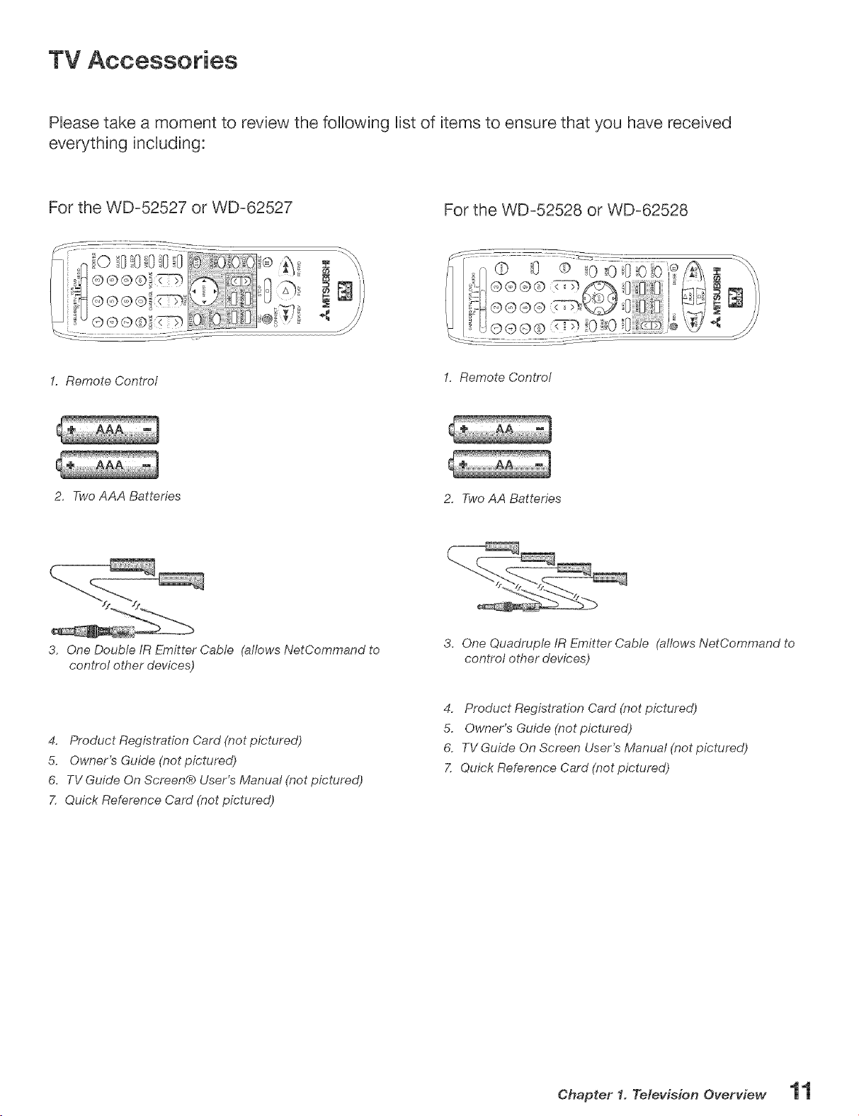
For the WD-52527 or WD-62527
For the WD-52528 or WD-62528
1. Remote Control
1. Remote Control
2, Two AAA Batteries
2, Two AA Batteries
3. One Double IR Emitter Cable (allows NetCommand to
control other devices)
3, One Quadruple IR Emitter Cable (allows NetCommand to
control other devices)
4. Product Registration Card (not pictured)
5. Owner's Guide (not pictured)
6, TV Guide On Screen® User's Manual (not pictured)
7, Quick Reference Card (not pictured)
4. Product Registration Card (not pictured)
5. Owner's Guide (not pictured)
6. TV Guide On Screen User's Manual (not pictured)
7, Quick Reference Card (not pictured)
Ohapter 1. Television Overview
Remote Controm Functions:
Overview
Figures or? the following page
D Slide Switch: Selects A/V product to be controlled by
the remote control. Select TV for NetCommand® device
control.
Q
in alphabetical order:
D ADJUST: Press _., _', _ and _ to navigate TV Guide
On Screen(b, menus, change settings, and move the _t_
PIP on-screen location. Operates many NetCommand
functions.
AUDIO: Selects and adjusts individual audio settings.
CANCEL/SUB: Clears SQV and some menu entries and
cancel recordings. For digital channels, adds separator _'_
between major and sub channel numbers.
CH(ANNEL}/PAGE: Scans up or down through
memorized channels. When used with TV Guide On
Screen(b, cable box, ChannelView, or satellite, moves up
or down one screen at a time.
CONNECT (WD°52528, WD-62528}: Initiates IEEE 1394
peer-to-peer connections.
@
_J DEVICE: Displays the Device Selection menu to
select the device to view (Ant-1 and Ant-2, or devices
connected to the TV's inputs).
DEVICE MENU: Displays or removes the options menu
for TV Guide On Screen and devices connected to TV
including CableCARD TM, display. For VCR or DVDs the
first press displays the transport menu.
}'_ ENTER(WD-52528, WD-62528}: Selects a channel
number or menu item.
ENTER/EXOH (WD-52527, WD-62527}: Selects a
channel number or menu item. Exchanges PIP or POP
and main TV picture.
EXCH (WD-52528, WD-62528}: Exchanges PIP or POP
and main TV picture.
FF/FWD: Fast forward or forward search with a VCR or
fast play a DVD. _,_
FORMAT: Changes the shape and size of the main TV
picture.
GUIDE: Displays or removes TV Guide On Screen or
ChanneWiew for Ant-1 and 2. Displays Track List for A/V
Disc. Displays program guide for satellite receiver, or
DVD Disc menu.
HOME: Exits TV on-screen menus and the TV Guide On
Screen system and returns to TV viewing. _"_
INFO: Displays an on-screen summary of the current
device used and any broadcast or V-Chip information
available. Cycles through available Info Box Sizes in the _'_
TV Guide On Screen system. See Appendix D for details.
12 Chapter 1. Television Overview
Light: Located on the left side for WD-52527 and
WD-62527 and on the right side for WD-52528 and
WD-62528 of the remote control, this feature illuminates
buttons or labels.
MUTE: Turns sound on or off.
Numbers: Individuatly selects channels or enters
information into menus.
PAUSE: Freeze a live TV picture when no PIP or POP
image is displayed. When PIP or POP image is visible,
pauses that image. Pauses a VCR, DVD or A/V Disc.
PIP CH: Scrolls up or down through memorized
channels for PIP source.
PIP DEVICE: Displays PIP Selection menu to select the
PIP or POP image source device.
PIP (WD_52527, WD _62527): Cycles th rough PIP choices.
PIP/POP (WD_52528, WD_62528}: Cycles through PIP
and POP choices.
PLAY: Plays the VCR, DVD or A/V Disc.
POWER: Turns power on and off for TV and other A/V
products.
QV (QuickViewTM}: Switches between the current
channel and last channel viewed.
REC (Record for WD-52528, WD-62528}: Records
with a VCR, sets up recordings for DVCR, IEEE 1394
devices, or while in ChannetView. When Listings
screen for TV Guide On Screen is displayed, will start a
recording.
REC/CONNECT (WD-52527, WD-62527}: Records
with a VCR, sets up recordings for DVCR, EEE 1394
devices, or while in ChannelView. Also initiates IEEE
1394 peer-to-peer connections. When Listings screen
for TV Guide On Screen is displayed, will start a
recording.
REW/REV: Rewinds or reverses search with a VCR.
Reverses scan with a DVD or A/V Disc.
SLEEP: Sets the TV to turn off within 2 hours. See page
14 for setup instructions.
SQV (SuperQuickViewTM}: Scans through memorized
lists of favorite channels.
STOP: Stops a VCR, DVD or A/V Disc.
TV MENU: Displays _VI_W_i_[ on-screen menu system.
V-CHIP: Turns On or Off the V-Chip Lock.
VIDEO: Selects and adjusts individual video settings.
VOLUME: Changes sound level.
Remote Controm Functions:
CABLE/DBS/DTV DVD
TV
POWER
DEVICE CHANNEL VOLUME
i_X AUDIO
cz2
PAGE
REC STOP PAUSE
CONNECT
REW/REV PLAY FF/FWD
MITSUBISH!
fD
0
m mmm
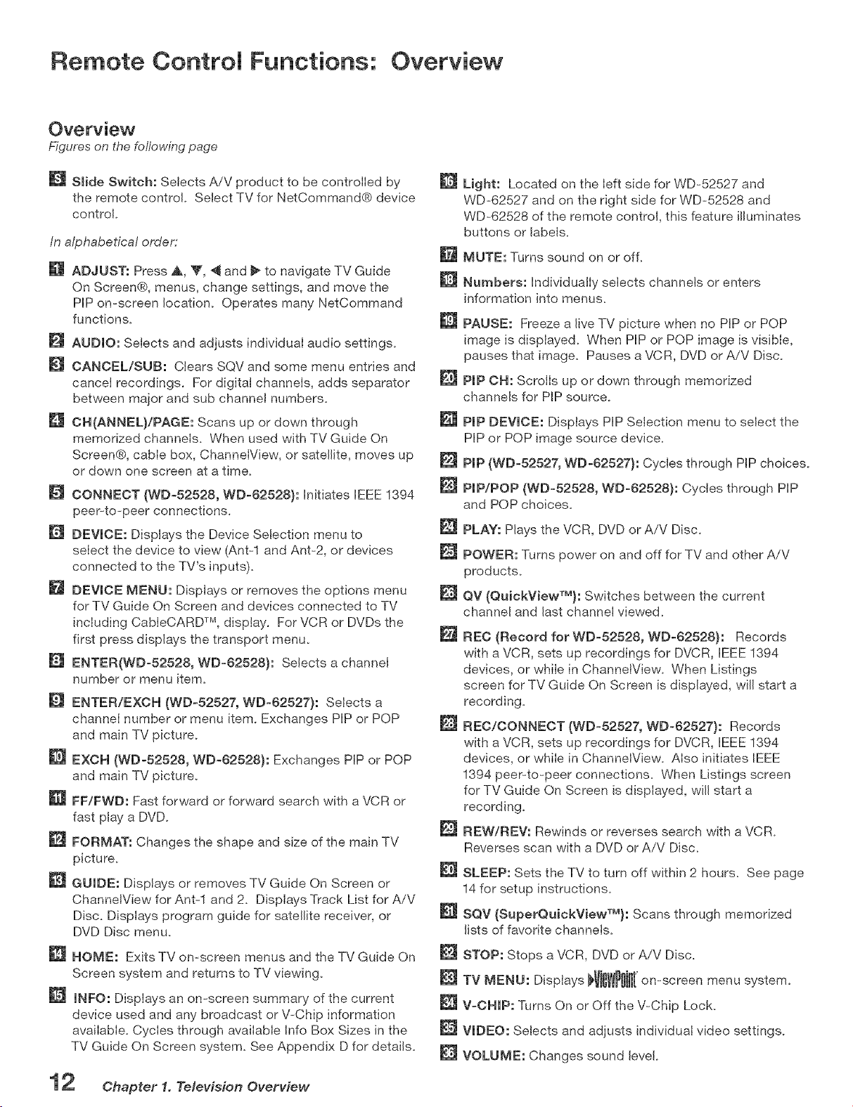
WD-52527 & WD-62527 Remote
WD-52528 & WD-62528 Remote
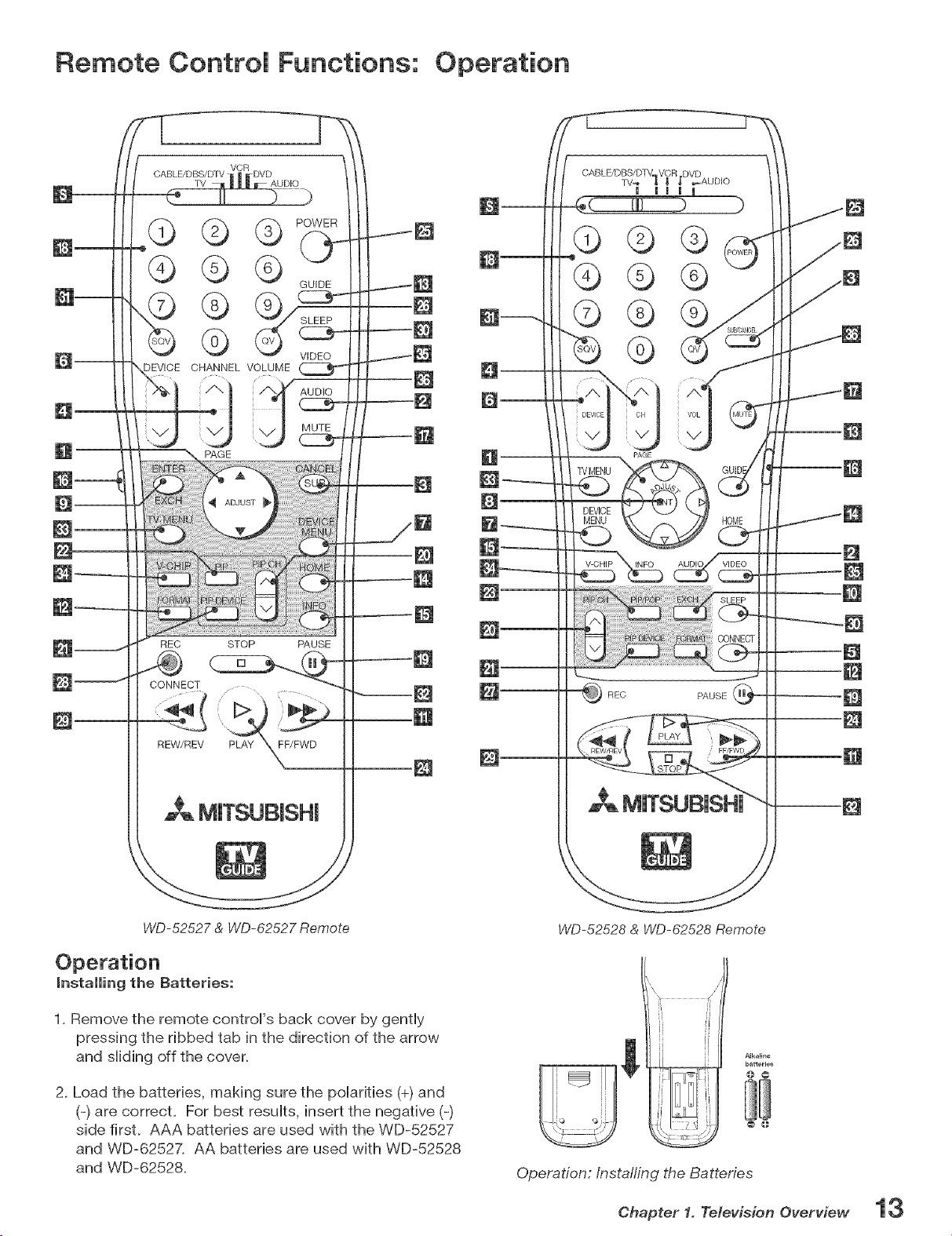
installing the Batteries:
1. Remove the remote controFs back cover by gently
pressing the ribbed tab in the direction of the arrow
and sHiding off the cover.
2. Load the batteries, making sure the poHarifies (+) and
(-) are correct. For best resuHts, insert the negative (-)
side first. AAA batteries are used with the WD-52527
and WD-62527. AA batteries are used with WD-52528
and WD-62528.
Alkaline
batteries
@ @
@ @
Operation:/nstafling the Batteries
Chapter 1. Television Overview
Remote Control Functions: Care and Sleep Timer
SJeep Timer
Setting the Sleep Timer:
1. Press SLEEP on the remote control
2. Each press of SLEEP increases the time dispHayed by
30 minutes, untiHthe maximum vaHueof 120 minutes is
reached.
3. After 5 seconds of inactivity, the message will
disappear.
4. Press SLEEP to view the remaining time before the
timer turns the TV off.
Canceling the Sleep Timer:
1. Press SLEEP to dispHay the on-screen message.
2. Press SLEEP repeatedHy untiHOFF is dispHayed.
Note: After 5 seconds of inactivity, the message
box disappears.
Hint: if the remote is in the TV layer and the TV will not
function, press POWER and 935 to reset the remote,
Care
For Best Results from the Remote Control:
Be within 20 feet of the equipmenL
Do not press two or more buttons at the same
time unless instructed.
Do not allow unit to get wet or become heated.
Avoid dropping on hard surfaces.
Do not use harsh chemicals to clean. Use only
a soft, lightly moistened cloth.
Do not mix new and old batteries.
Do not heat, take apart or throw batteries into
fire.
Use only alkaline batteries.
Ohapter 1. Television Overview
Front Control Panel
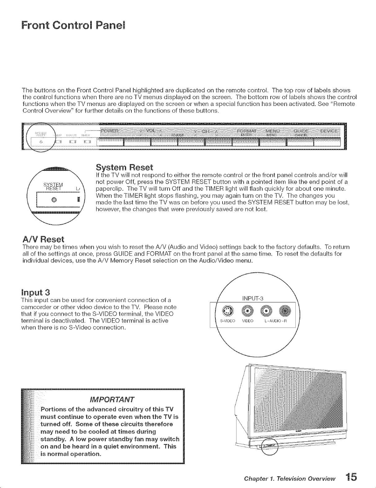
The buttons on the Front Control Panel higHighted are duplicated on the remote control. The top row of labels shows
the control functions when there are no TV menus displayed on the screen. The bottom row of labels shows the control
functions when the TV menus are displayed on the screen or when a special function has been activated. See "Remote
Control Overview" for further details on the functions of these buttons.
System Reset
If the TV will not respond to either the remote control or the front panel controls and/or will
not power Off, press the SYSTEM RESET button with a pointed item like the end point of a
paperclip. The TV will turn Off and the TIMER light will flash quickly for about one minute.
When the TIMER light stops flashing, you may again turn on the TV. The changes you
made the last time the TV was on before you used the SYSTEM RESET button may be lost,
however, the changes that were previously saved are not lost.
A/V Reset
There may be times when you wish to reset the AiV (Audio and Video) settings back to the factory defaults. To return
all of the settings at once, press GUIDE and FORMAT on the front panel at the same time. To reset the defaults for
individual devices, use the AiV Memory Reset selection on the Audio/Video menu.
input 3
This input can be used for convenient connection of a
camcorder or other video device to the TV. Please note
that if you connect to the S-VIDEO terminal, the VIDEO
terminal is deactivated. The VIDEO terminal is active
when there is no S-Video connection.
iMPORTANT
Portions of the advanced circuitry of this TV
must continue to operate even when the TV is
turned off. Some of these circuits therefore
may need to be cooled at times during
standby. A low power standby fan may switch
on and be heard in a quiet environment. This
is normal operation,
Chapter 1. Te/evision Overview
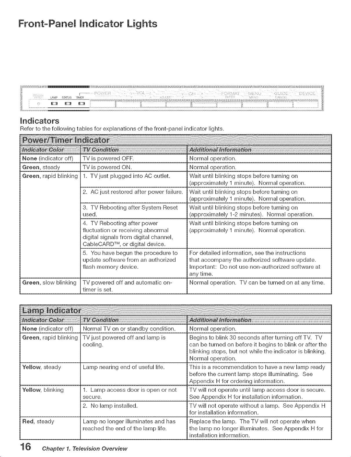
FrontoPanei Indicator Lights
LAMF' STATUS "riMER
.......E, ......
Refer to the following tables for explanations of the front-panel indicator lights.
None (indicator off)
Green, steady
Green, rapid blinking
Green, slow blinking
TV is powered OFF.
TV is powered ON.
1. TVjust plugged into AC outlet.
2. AC just restored after power failure.
3. TV Rebooting after System Reset
used.
4. TV Rebooting after power
fluctuation or receiving abnormal
digital signals from digital channel,
CableCARD TM, or digital device.
5. You have begun the procedure to
update software from an authorized
flash memory device.
TV powered off and automatic on-
timer is seL
Normal operation.
Normal operation.
Wait until blinking stops before turning on
(approximately 1 minute). Normal operation.
Wait until blinking stops before turning on
(approximately 1 minute). Normal operation.
Wait until blinking stops before turning on
(approximately 1-2 minutes). Normal operation.
Wait until blinking stops before turning on
(approximately 1 minute). Normal operation.
For detailed information, see the instructions
that accompany the authorized software update.
Important: Do not use non-authorized software at
any time.
Normal operation. TV can be turned on at any time.
None (indicator off) Normal TV on or standby condition. Normal operation.
Green, rapid blinking TV just powered off and lamp is Begins to blink 30 seconds after turning off TV. TV
cooiing, can be turned on before it begins to biink or after the
blinking stops, but not while the indicator is blinking.
Normal operation.
Yellow, steady Lamp nearing end of useful life. This is a recommendation to have a new lamp ready
before the current lamp stops illuminating. See
Appendix H for ordering information.
Yellow, blinking 1. Lamp access door is open or not TV will not operate until lamp access door is secure.
secure. See Appendix H for installation information.
2. No lamp installed. TV wiii not operate without a lamp. See Appendix H
for installation information.
Red, steady Lamp no ionger iiiuminates and has Replace the lamp. The TV wiii not operate when
reached the end of the lamp life. the lamp no longer illuminates. See Appendix H for
installation information.
16 Ohapter 1. Television Overview
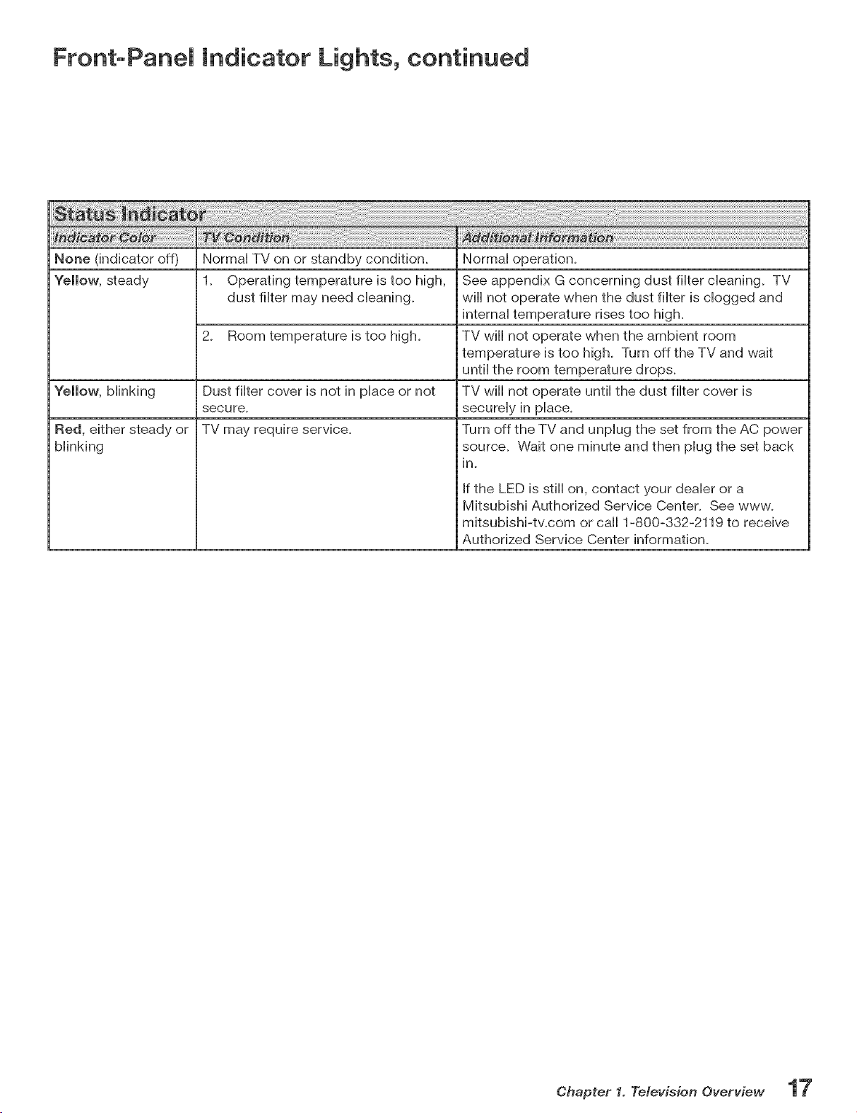
FrontoPanem Indicator Lights, continued
None (indicator off) NormaH TV on or standby condition.
"follow, stoady 1. Operating tomporaturo is too high,
dust fiHter may hood cHeaning.
2. Room tomporaturo is too high.
Dust fiHter covor is not in pHace or not
secure.
TV may require service.
"fellow, bHinking
Red, either stoady or
bHinMng
NormaH operation.
See appendix G concerning dust fiHtercHeaning. TV
will not operate when the dust flHter is dogged and
internaHtemperature rises too high.
TV will not operate when the ambient room
temperature is too high. Turn off the TV and wait
until the room temperature drops.
TV will not operate until the dust filter cover is
securely in place.
Turn off the TV and unplug the set from the AC power
source. Wait one minute and then plug the set back
in.
If the LED is still on, contact your dealer or a
Mitsubishi Authorized Service Center. See www.
mitsubishi-tv.com or call 1-800-332-2119 to receive
Authorized Service Center information.
Chapter 1. Te/evision Overview
Back Panem
3. 4.
7m
5,
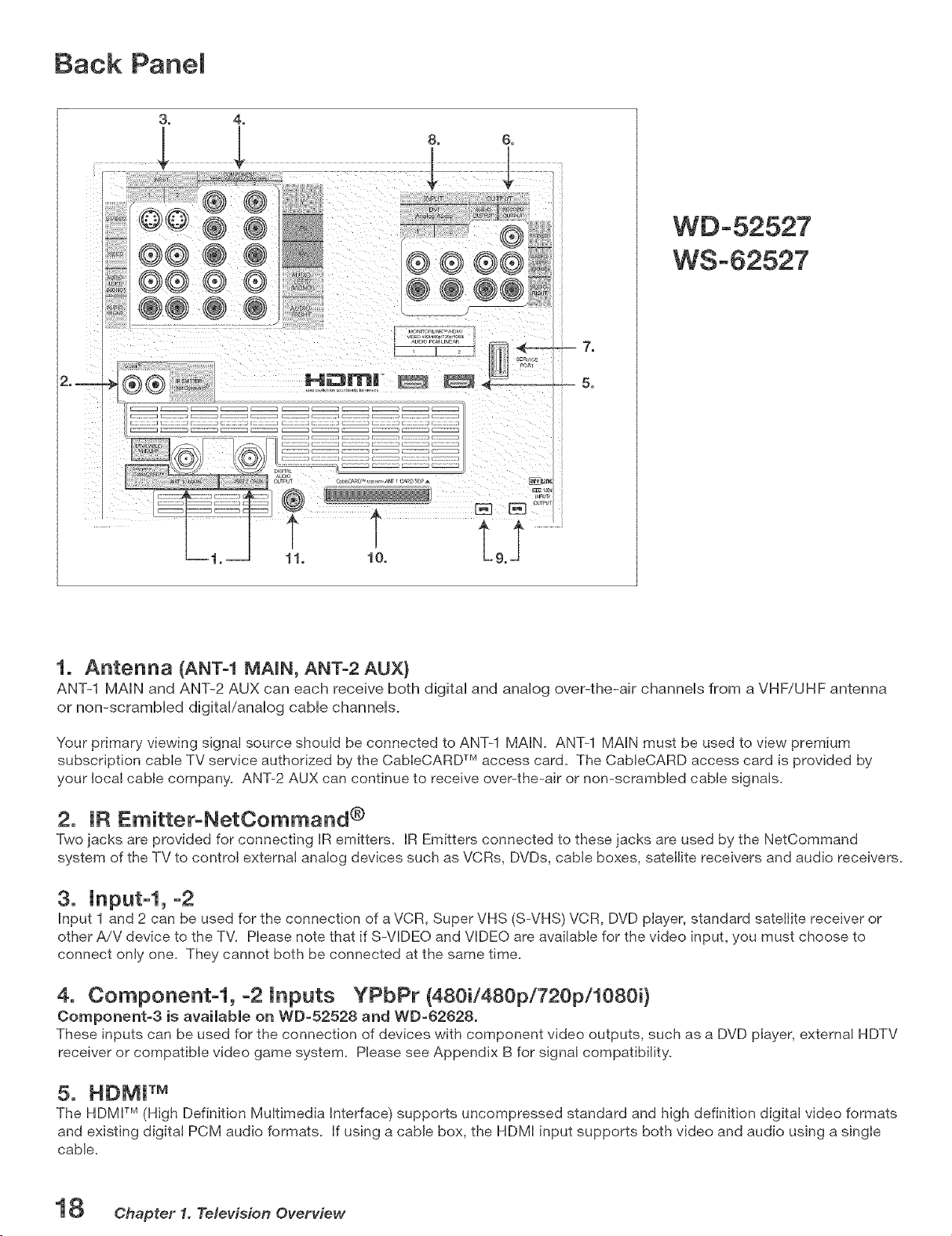
1. Antenna (ANT-1 MAmN, ANT-2 AUX}
ANT-1 MAIN and ANT-2 AUX can each receive both digital and analog over-the-air channels from a VHF/UHF antenna
or non-scrambled digital/analog cable channels.
Your primary viewing signal source should be connected to ANT-1 MAIN. ANT-1 MAIN must be used to view premium
subscription cable TV service authorized by the CableCARD TM access card. The CabteCARD access card is provided b
your local cable company. ANT-2 AUX can continue to receive over-the-air or non-scrambled cable signals.
2. IR Emitter-NetCommand ®
Two jacks are provided for connecting IR emitters. IR Emitters connected to these jacks are used by the NetCommand
system of the TV to control external analog devices such as VCRs, DVDs, cable boxes, satellite receivers and audio receivers.
3. Input-l,-2
Input 1 and 2 can be used for the connection of a VCR, Super VHS (S-VHS) VCR, DVD player, standard satellite receiver or
other A/V device to the TV. Please note that if S-VIDEO and VIDEO are available for the video input, you must choose to
connect only one. They cannot both be connected at the same time.
4. Component-I, -2 inputs YPbPr (480i/480p/720p/1080i}
Component-3 is available on WD-52528 and WD-62628o
These inputs can be used for the connection of devices with component video outputs, such as a DVD player, external HDTV
receiver or compatible video game system. Please see Appendix B for signal compatibility.
5. HDMJ TM
The HDMV M (High Definition Multimedia Interface) supports uncompressed standard and high definition digital video formats
and existing digital PCM audio formats. If using a cable box, the HDMI input supports both video and audio using a single
cable.
18 Chapter 1. Television Overview
Back Panel, continued
k
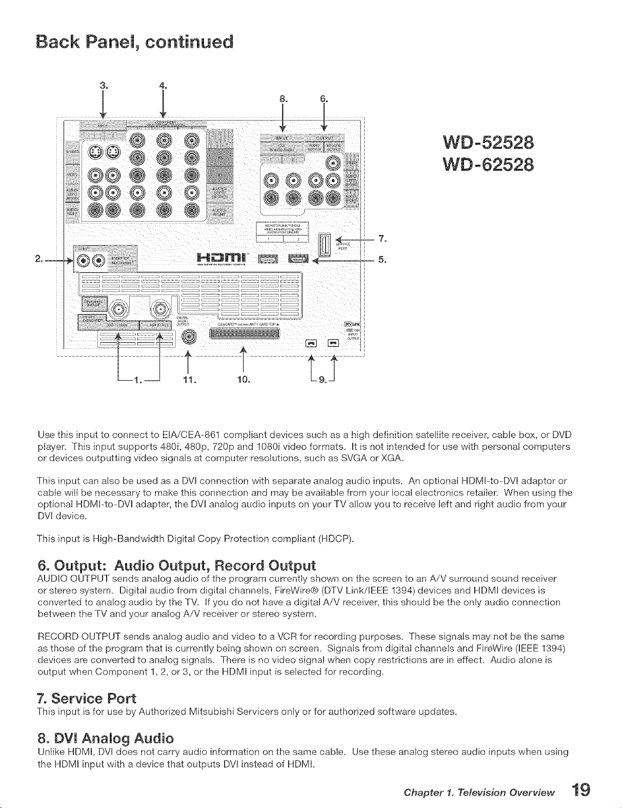
Use this input to connect to EIA/CEA-861 compliant devices such as a high definition satellite receiver, cable box, oF DVD
player, This input supports 480i, 480p, 720p and 1080i video formats, It is not intended for use with personal computers
or devices outputting video signals at computer resolutions, such as SVGA or XGA,
This input can also be used as a DVI connection with separate analog audio inputs, An optional HDMI-to-DVI adaptor or
cable will be necessary to make this connection and may be available from your local electronics retailer, When using the
optional HDMI-to-DVl adapter, the DVl analog audio inputs on your TV allow you to receive left and right audio from your
DVl device,
This input is High-Bandwidth Digital Copy Protection compliant (HDCP),
6. Output: Audio Output, Record Output
AUDIO OUTPUT sends analog audio of the program currently shown on the screen to an A/V surround sound receiver
o_ stereo system, Digital audio from digital channels, FireWire@ (DTV Link/IEEE 1394) devices and HDMI devices is
converted to analog audio by the TW If you do not have a digital A/V receiver, this should be the only audio connection
between the TV and you_ analog A/V _eceive_ o_ stereo system,
RECORD OUTPUT sends analog audio and video to a VCR for recording purposes, These signals may not be the same
as those of the program that is currently being shown on screem Signals from digital channels and FireWire (IEEE 1394)
devices are converted to analog signals, There is no video signal when copy rest_ictions are in effecL Audio alone is
output when Component 1, 2, o_ 3, o_ the HDMI input is selected for reco_ding,
7. Service Port
This input is for use by Authorized Mitsubishi Se_vice_s only or for authorized software updates,
8. DVI Analog Audio
Unlike HDMI, DVl does not carry audio information on the same cable, Use these analog stereo audio inputs when using
the HDMI input with a device that outputs DVl instead of HDMI,
Chapter 1. Television Overview 19

Back Panel, continued
9. DTV Link/JEEE 1394
These jacks allow the TV to connect to external IEEE 1394 digital products by means of a single cable. Two jacks are
provided for this purpose, allowing for a high degree of flexibility in connecting your NetCommand®=controlJed system.
Detailed information regarding EEE 1394 connection requirements are in Chapter 4.
10. CabJeOARD TM SJot
The CabIeCARD access card provided by your cable TV service provider is inserted into this slot. The top of the card should
face up as indicated by the direction of the CARD TOP arrow. When you use the CabJeCARD Slot, you must connect the
cable to ANT=I.
CabJeCARD is a nationwide standard system that allows your local cable TV provider to supply you with an access card
customized to your account. This card allows the TV to receive, decode and unscramble the premium digital channels
included in your cable TV subscription without the use of a cable box. See page 22 for additionaJ CabJeCARD information
and activation instructions.
If your cable company is not currently offering CabIeCARD access cards, you wiJJneed to use a cable box provided and
authorized by your JocaJ cable company to view scrambled channels.
11. DigitaJ Audio Output
This output sends Dolby® Digital or PCM digital audio to your digital A/V surround sound receiver. Analog audio from analog
channels and devices is converted by the TV to PCM digital audio. In most cases, this should be the only audio connection
between the TV and your A/V receiver. If you have MP3 audio sources, however, you need to connect the TV's analog
AUDIO OUTPUT (left and right) to your A/V receiver.
A Note About Temporary ResiduaJ images
Prolonged display of stationary images on your TV may cause faint, residual "ghost" images to be visible when viewing
other programs. THIS EFFECT IS TEMPORARY. The residual images will disappear within days or weeks. Most TV
and DVD programming is of generally uniform brightness and will not produce this effect.
To prevent the appearance of residual images:
Avoid display of stationary images for extended periods on this or any other LCD projection TV. Examples of such
images include:
Stationary images that may be part of video games and web pages
Bright, stationary icons overlaid on moving video
Side bars displayed with narrow-format video (see ddinition on page 80)
Top and bottom bars displayed with letter-box video (see definition on page 80)
Mix regular TV and video programming with uses that display stationary images.
Ohapter 1. Television Overview
ii!!i_!i!!_i!i_i!!ii!!i!i_i!!_i_!i_i_i!!i_i!!!i!i!ilili!i_,!_i!_i,!_i!i_!ii!!ii!!iii'i!i!_i_!i_i¸iiii!i_!¸!,!!iii!_!i_ii_!_!_!!!i!¸ii¸iili¸i_!!!_!!i!!ii_i_¸!i_!!!i!i_iil¸_i_!ii_ill¸!i_ii_!il¸ii_!!!i_iiill!i!i!i!!_i_!il!iii!i__i_i¸!_!!i_i!!!i',_i!i_!!¸ii_iiii!i'ii!!_il,ii'_!i!_iii_'il,ii_i!_;_!i,ii'_iii_i!iii!_i_!i_i!_!ilii_iii_il¸ii'll!!_i_!i!i_!i!_ii_i_!iii!i_i'!!¸ii!i!'__i_!!_i_i!ii!_il¸_ii_iii!__ii!i__i!i_i_!ilii!!i',ii_i!i,ii!ili!i!!ii_!!__ii!!_i!i!!i!!!!i_!_i!_i!!i_i!i_!_i!i_ii!!ii!i!i_iiii!!_!!_i_!!i_i!¸iiiiii!iil!i¸,i_!!i_i!ii!_i!!i!!ii!_i_!ii_ii!_i_!!i!i!!i!ii!i!i_ii!!_i!_!i_i_iil¸!i_!iiii_i_ii!i!i_i!!i_!il¸!i_iil!i'_'ii_iliiiiiii!ili!_i_i_iiii!i!!_i'_ii!ii_,_!i¸ii_!ii!!_ii!ii_!i!iiiii!¸!i_i_i_il!i!i!!!i!!il_i!_!i!!'i_i_!!_!_!ii!i!i!iii!!ii!!ii!ii!!i!!i_!iii!i!!i'!i_i_!i!ii_ii¸ii'!i!ii_!i'_il!i_ii!i_!i_ii!i,!i!iiiii_'i_!i!_i!!ii_iii__ii_i!!!!_!!!i_i_!ii_!iii_!!i_!i!ii_i_!i'i_i!i!i!i!!i_!i_!_!!!!i!!iii!ii_i_!!_i_!i!_i!!_i_i!!_!ii!i_ii!!i_i!!_!i_!i!ii!_il!i!!i_i!i!!i!!i!i_i'¸i!'_il_i!!i!_i!i!!i_i_!i_i!!_i_i!'iii_'_i!_!i_!il¸_i!,_i!i!!!i!!ii!ii_!i_!i!_!i¸_i_i!'_'ii!i'_!il_i!¸ii'!!!_i_!i!_i!i!!!i!¸!i_iiiii!i!iii_i!i_i!ilili_i!_!i!!i_i!_i!iii!!i!i!ii!_!i_iii!!_i!!_i!i_i!iiiiiiii!i_i_!!il,ii_i!!i!i!!ii__i!_ii¸'ii_ili_ii!_i_!ii_!i_!!i_i!_ii_!i!_i!i_il¸!i_!ii¸ii_i!i_ii!!i_ii_ii_!!!if!!¸ii_!i'i_!ii_ilii_i!i_i_¸i!_i_!!_i!i_iii!_i_!!i!ii'_!i!!iiiii!_!i_i!_ii!ii!_!i'!!i_!ii_ii_ili!_ii'__i!!i_iii_'il!i_ili!!_i!!i!_!!i_!!i_!!_!ii!!!ii!_ii_i_!ili!_!!i_i_i!_i_ii!!i!_i_¸ii'_'il_i_i!i,_i!!i!¸!ilii_i!i!!_i!!_!i!_!ii_!!i¸_i!!i_!!!!ii!!i!_!ii!i!i_ilii_,_i!i_ii!i_!i_ii!i_ii!i_i!i_i!i_ii!_!i!iiii!i!ii!ilii_!il_il¸ii'_ii!ii!i!!i!!,!i!i_ii!i¸!_i!_i'_i!i_!i!i_iii!_i!ii!_!!!i'_!!_'ii!i!iil¸!i¸_i"i'!i¸_i_¸!i_i!i!i'_ii_i!i_i_!!ii!_!i!ii!ii_i!¸!i_!
Connecting
E×terna_ Devices & NetCommand® Setup ........................................... 22
Wall Out_et Cable or Cable Box ............................................................. 23
Cab_eCARD TM Tech no_ogy ...................................................................... 24
Antenna with Single Lead ...................................................................... 25
Antennas with Separate UHF and VHF Leads ..................................... 25
VCR to an Antenna or Wall Out_et Cable .............................................. 26
VCR Video and Audio to TV .................................................................... 26
VCR Video and Audio to a Cable Box .................................................... 27
A/V Receiver or Stereo System ............................................................. 28
Satellite Receiver or Other Device with S=Video ................................. 28
DVD P_ayer with Component Video ....................................................... 29
HDTV Cable Box or Satellite Receiver with Component Video .......... 29
HDMI Device ............................................................................................ 30
DW Device ................................................................................................ 30
IR Emitter NetCommand® ..................................................................... 31
Compatible IEEE 1394 Devices .............................................................. 32
He_pfu_ Hints ............................................................................................ 34
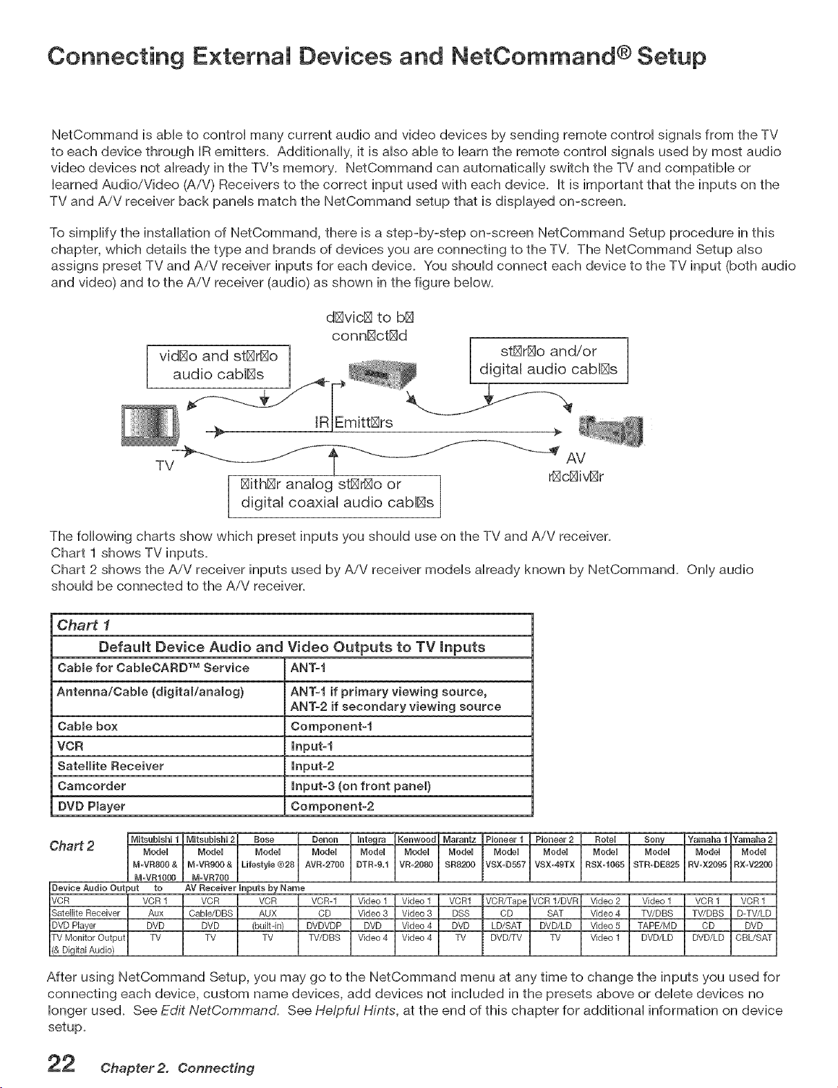
Connecting E×temai Devices and NetCommand ® Setup
NetCemmand is able to contrel many current audio and video devices by sending remote centrel signals from the TV
to each device through IR emitters. Additionally, it is also able to barn the remote control signals used by most audio
video devices not already in the TV's memory. NetCommand can automatically switch the TV and compatible or
learned Audio/Video (A/V) Receivers to the correct input used with each device. It is important that the inputs on the
TV and AiV receiver back panels match the NetCommand setup that is displayed on-screen.
To simplify the installation ef NetCommand, there is a step-by-step on-screen NetCommand Setup procedure in this
chapter, which details the type and brands of devices you are connecting to the TV. The NetOommand Setup aUso
assigns preset TV and AiV receiver inputs for each device. You should connect each device to the TV input (both audio
and video) and to the AiV receiver (audio) as shown in the figure below.
vidBo and stBrBo
audio cablBs
÷
stl_rl_o and/or 1
Uig ta aud o cab_s J
TV AV
_c@v_r
@thBr analog stl_o or
digital coaxial audio cabIBs
The following charts show which preset inputs you should use en the TV and AiV receiver.
Chart 1 shows TV inputs.
Chart 2 shows the AiV receiver inputs used by AiV receiver models already known by NetCommand. Only audio
should be connected to the AiV receiver.
Chart f
Default Device Audio and Video Outputs to TV mnputs
Cabmefor CableOARD TM Service ANT-f
Antenna/Oabme (digitam/anamog} ANT-f if primary viewing source,
ANT-2 if secondary viewing source
Oabmebox Oomponent-f
VCR Input-1
Satellite Receiver Input-2
Camcorder Input-3 (on front panel}
DVD Player Component-2
Chart 2
D[DeviceAudio Output to AV Receiver inputs by Name
[VCR VClVCR1 EVeR _ VCR _ VCR-1 __LVCR1 kCRfrapekCR1/DVRI Video2 I Video1 LVCR1 _VCR1
SLSatelliteReceiver LAux ChOable/DBS _ AUX _ CD Vi_3 I Video3 I DS_ I CD _ SAT VhVideo4 _ TLTV/DBS LD-TV/LD
DVDPlayer DVD DVD (built-in)
TV Monitor Output TV TV TV
& Dgta Audo
After using NetCemmand Setup, you may ge to the NetCommand menu at any time to change the inputs you used fer
connecting each device, custom name devices, add devices net included in the presets above er delete devices no
lenger used. See Edit NetCommand. See Helpful Hints, at the end of this chapter for additional information on device
setup.
Chapter 2. Cennecdng
Connecting a Wail Outlet Cable or Cable Box
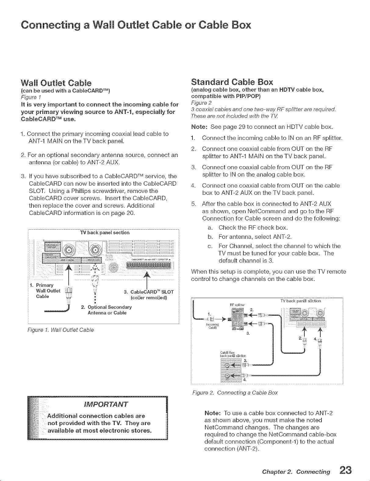
Wall OutJet CabJe
(can be used with a OableOARD TM)
Figure 1
it is very important to connect the incoming cable for
your primary viewing source to ANT=l, especially for
CableOARD TM use.
1. Connect the primary incoming coaxiai Headcame to
ANT-1 MAiN on the TV back panel
2. For an optional secondary antenna source, connect an
antenna (or cable) to ANT-2 AUX.
3. If you have subscribed to a CableCARD TM service, the
CableCARD can now be inserted into the CableCARD
SLOT. Using a Phillips screwdriver, remove the
CableCARD cover screws. Insert the CableCARD,
then replace the cover and screws. Additional
CableCARD information is on page 20.
TV back panet section
{coiner rerno[_ed)
m
2. Optional Secondary
Antenna or Cable
Figure 1. Walt Outlet Cable
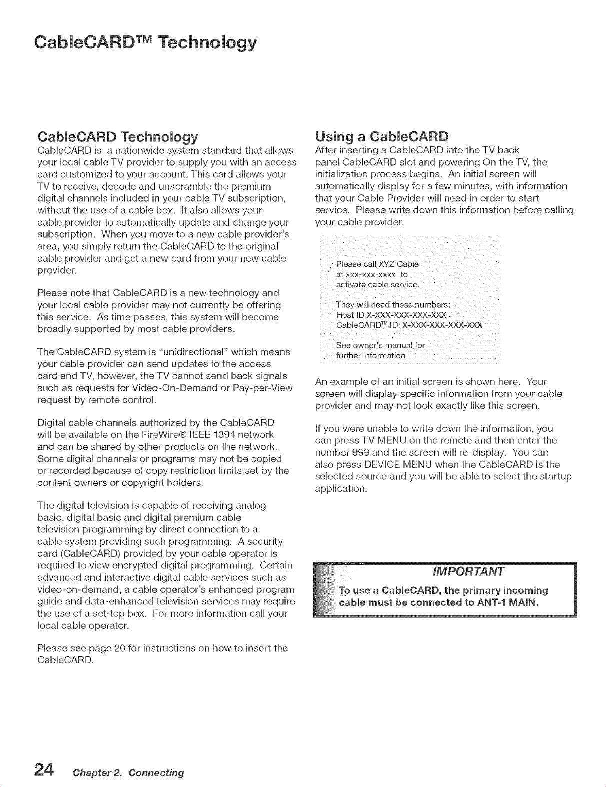
Standard CabJe Box
(analog cable box, other than an HDTV cabmebox,
compatibme with PIP/POP}
Figure 2
3 coaxial cables and one two-way RF spfitter are required,
Theseare not included with the T_Z
Note: See page 29 to connect an HDTV cable box.
1. Connect the incoming cable to IN on an RF splitter.
2. Connect one coaxial cable from OUT on the RF
splitter to ANT-1 MAIN on the TV back panel.
3. Connect one coaxial cable from OUT on the RF
splitter to IN on the analog cable box.
4. Connect one coaxial cable from OUT on the cable
box to ANT-2 AUX on the TV back panel.
5_ After the cable box is connected to ANT-2 AUX
as shown, open NetCommand and go to the RF
Connection for Cable screen and do the following:
a. Check the RF check box.
b. For antenna, select ANT-Z
c. For Channel, select the channel to which the
TV must be tuned for your cable box. The
default channel is 3.
When this setup is complete, you can use the TV remote
control to change channels on the cable box.
L TV back panBI s[Sction
RF splitter
s-. r
! <--_ .......
CablE] Box
back panBI sBction
3=
4.
Figure 2, Connecting a Cable Box
Note: To use a cable box connected to ANT=2
as shown above, you must make the noted
NetCommand changes. The changes are
required to change the NetCommand cable=box
default connection (Component=l) to the actual
connection (ANT-2).
Chapter2. Connecting 23
CabieCARD TMTechnology
CabJeCARD TechnoJogy
CableCARD is a nationwide system standard that allows
your local cable TV provider to supply you with an access
card customized to your account. This card allows your
TV to receive, decode and unscramble the premium
digital channels included in your cable TV subscription,
without the use of a cable box. It also allows your
cable provider to automatically update and change your
subscription. When you move to a new cable provider's
area, you simply return the CableCARD to the original
cable provider and get a new card from your new cable
provider.
Please note that CableCARD is a new technology and
your local cable provider may not currently be offering
this service. As time passes, this system wiii become
broadly supported by most cable providers.
The CableCARD system is "unidirectional" which means
your cable provider can send updates to the access
card and TV, however, the TV cannot send back signals
such as requests for Video-On-Demand or Pay-per-View
request by remote control.
Digital cable channels authorized by the CableCARD
wiii be available on the FireWire® [EEE 1394 network
and can be shared by other products on the network.
Some digital channels or programs may not be copied
or recorded because of copy restriction limits set by the
content owners or copyright holders.
The digital television is capable of receiving analog
basic, digital basic and digital premium cable
television programming by direct connection to a
cable system providing such programming. A security
card (CabieCARD) provided by your cable operator is
required to view encrypted digital programming. Certain
advanced and interactive digital cable services such as
video-on-demand, a cable operator's enhanced program
guide and data-enhanced television services may require
the use of a set-top box. For more information caii your
local cable operator.
Please see page 20 for instructions on how to insert the
CabieCARD.
Using a CabJeCARD
After inserting a CableCARD into the TV back
panel CableCARD slot and powering On the TV, the
initialization process begins. An initial screen wiii
automatically display for a few minutes, with information
that your Cable Provider wiii need in order to start
service. Please write down this information before calling
your cable provider.
Please call XYZ CaDte
aI XXX-XXX=XXXX 1:o
ac1: va1:e CaDle service.
They wu_ neea 1:nese numbers
Host ID X-XXX-XXX-XXX-XXX
CableCARD TM [D: X-XXX-XXX-XXX-XXX
See owner's manual for
further information
An example of an initial screen is shown here. Your
screen wiii display specific information from your cable
provider and may not look exactly like this screen.
If you were unable to write down the information, you
can press TV MENU on the remote and then enter the
number 999 and the screen will re-display. You can
also press DEVICE MENU when the CableCARD is the
selected source and you will be able to select the startup
application.
Chapter 2. Connecting
Connecting an Antenna with a Single Lead or Antennas with
Separate UHF and VHF Leads
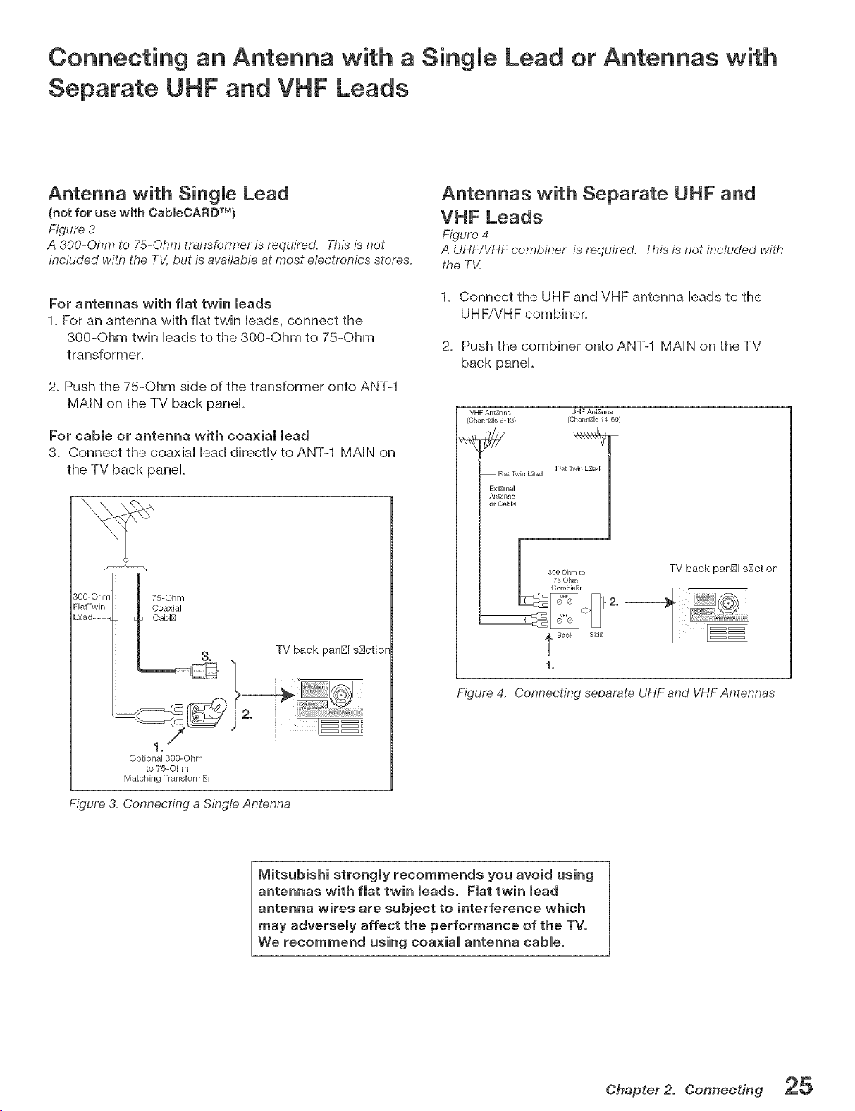
Antenna with Single Lead
(not for use w{th CabmeCARDTM}
Figure 3
A 300-Ohm to 75-Ohm transformeris required. This is not
included with the TV,but is available at most electronics stores.
For antennas with flat twin leads
1. For an antenna with flat twin leads, connect the
300-Ohm twin leads to the 300-Ohm to 75-Ohm
transformer.
2. Push the 75-Ohm side of the transformer onto ANT-1
MAIN on the TV back panel.
For cable or antenna with coaxial lead
3. Connect the coaxial lead directly to ANT-1 MAIN on
the TV back panel.
_0'O"rO"r'_"_ad--__ii:i'77°'1t_'_
I "_ TV back partial s[_ction
Optional 300-Ohm
to 75--©hm
Matching rransformNr
Figure 3. Connecting a Single Antenna
Antennas with Separate UHF and
VHF Leads
Figure 4
A UHF/VHF combiner is required, This is not included with
the TV.
1. Connect the UHF and VHF antenna leads to the
UHF/VHF combiner.
2. Push the combiner onto ANT-1 MAIN on the TV
back panel.
VHF AntBrLna UHF AntBr_na
(Char_l_ls 2 13) (Char_nBIs 14 69)
Flat ]_vin LBad
Flat ]_vin L_ad
Exf_mal
or Cab_
TV back pan[_l s[_ction
i,
Figure 4. Connecting separate UHF and VHF Antennas
lVlitsubishi strongly recommends you avoid using
antennas with flat twin leads. Flat twin lead
antenna wires are subject to interference which
may adversely affect the performance of the TV.
We recommend using coaxial antenna cable.
Chapter 2. Connecting
Connecting a VCR to Antenna or Wail Outlet Cable
Connecting VCR Video and Audio to the TV
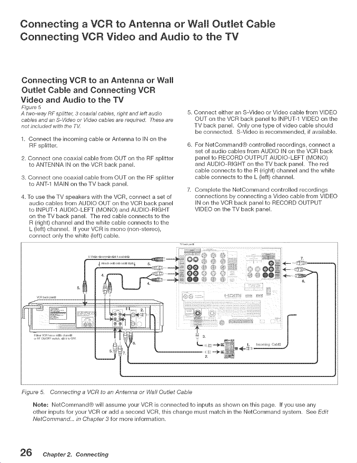
Connecting VCR to an Antenna or Wall
OutJet CabJe and Connecting VCR
Video and Audio to the TV
Figure 5
A two-way RF splitter, 3 coaxial cables, right and left audio
cables and an S-Video or Video cables are required. These are
not included with the T_/;
1. Connect the incoming cable or Antenna to IN on the
RF splitter.
5,
2. Connect one coaxial cable from OUT on the RF splitter
to ANTENNA IN on the VCR back panel.
6,
3. Connect one coaxial cable from OUT on the RF splitter
to ANT-1 MAIN on the TV back panel.
4, To use the TV speakers with the VCR, connect a set of
audio cables from AUDIO OUT on the VCR back panel
to iNPUT-1 AUDIO-LEFT (MONO) and AUDIO-RIGHT
on the TV back panel, The red cable connects to the
R (right) channel and the white cable connects to the
L (left) channel, If your VCR is mono (non-stereo),
connect only the white (left) cable,
VCR back panUJ
ff Bout VCR has a vidB0 channBI
or RF ON/OFF sw_tch, sNt it to OFR
Connect either an S-Video or Video cable from VIDEO
OUT on the VCR back panel to INPUT-1 VIDEO on the
TV back panel. Only one type of video cable should
be connected. S-Video is recommended, if available.
For NetCommand@ controlled recordings, connect a
set of audio cables from AUDIO IN on the VCR back
panel to RECORD OUTPUT AUDIO-LEFT (MONO)
and AUDIO-RIGHT on the TV back panel. The red
cable connects to the R (right) channel and the white
cable connects to the L (left) channel.
Complete the NetCommand controlled recordings
connections by connecting a Video cable from VIDEO
IN on the VCR back panel to RECORD OUTPUT
VIDEO on the TV back panel.
@@
@@
1, Incoming CabIB
Figure 5. Connecting a VCR to an Antenna or Waft Outlet CaMe
Note: NetCommand@ wiii assume your VCR is connected to inputs as shown on this page. If you use any
other inputs for your VCR or add a second VCR, this change must match in the NetCommand system. See Edit
NetCommand... in Chapter 3 for more information,
2_ Chapter2. Connecting
Connecting VCR Video and Audio to a Cable Box
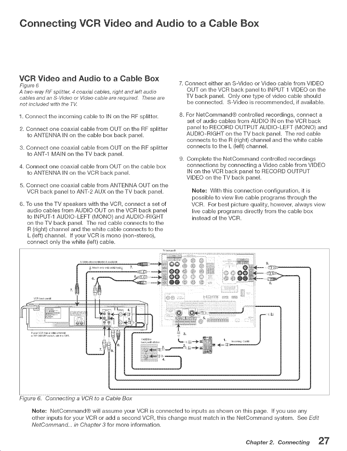
VCR Video and Audio to a Cable Box
Figure 6
A two-way RF spfitter, 4 coaxial cables, right and left audio
cables and an S-Video or Video cable are required, These are
not included with the T_:
7. Connect either an S-Video or Video came from VIDEO
OUT on the VCR back pane[ to INPUT 1 VIDEO on the
TV back pane[. Only one type of video cable should
be connected. S-Video is recommended, if available.
1. Connect the incoming cable to IN on the RF splitter.
2. Connect one coaxial came from OUT on the RF splitter
to ANTENNA IN on the cable box back pane[.
3. Connect one coaxial came from OUT on the RF splitter
to ANT-1 MAIN on the TV back pane[.
4. Connect one coaxial came from OUT on the cable box
to ANTENNA IN on the VCR back pane[.
5. Connect one coaxial came from ANTENNA OUT on the
VCR back pane[ to ANT-2 AUX on the TV back pane[.
6. To use the TV speakers with the VCR, connect a set of
audio cables from AUDIO OUT on the VCR back pane[
to INPUT-1 AUDIO-LEFT (MONO) and AUDIO-RIGHT
on the TV back pane[. The red cable connects to the
R (right) channel and the white came connects to the
L ([eft) channel If your VCR is mono (non-stereo),
connect only the white ([eft) came.
VCR back panml
I1 you1 VCR has a vidBo chat nBI
o RF ON/OFF switch, sBt it to OFR
8.
For NetCommand® controlled recordings, connect a
set of audio cables from AUDIO IN on the VCR back
pane[ to RECORD OUTPUT AUDIO-LEFT (MONO) and
AUDIO-RIGHT on the TV back pane[. The red came
connects to the R (right) channel and the white cable
connects to the L ([eft) channel
g.
Complete the NetCommand controlled recordings
connections by connecting a Video cable from VIDEO
IN on the VCR back pane[ to RECORD OUTPUT
VIDEO on the TV back pane[.
Note: With this connection configuration, it is
possible to view live cable programs through the
VCR. For best picture quality, however, always view
live came programs directly from the cable box
instead of the VCR.
Cabl_ Box 1.
back panel s_ctiol/ Incoming Oablm
Figure 6. Connecting a VCR to a CaMe Box
Note: NetCommand® wiii assume your VCR is connected to inputs as shown on this page. If you use any
other inputs for your VCR or add a second VCR, this change must match in the NetCommand system. See Edit
NetCommand... in Chapter 3 for more information.
Chapter 2. Connecting
Connecting an AiV Receiver (Stereo System}
Connecting a Satellite Receiver or Other Device with S wVideo
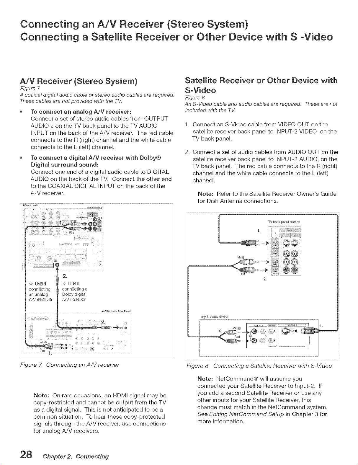
A/V Receiver (Stereo System}
Figure 7
A coaxial digital audio cable or stereo audio cables are required.
These cables are not provided with the TV.
To connect an analog A/V receiver:
Connect a set of stereo audio cables from OUTPUT
AUDIO 2 on the TV back panel to the TV AUDIO
INPUT on the back of the AiV receiver. The red cable
connects to the R (right) channel and the white cable
connects to the L (left) channel.
To connect a digital A/V receiver with Dolby®
Digital surround sound:
Connect one end of a digital audio cable to DIGITAL
AUDIO on the back of the TV. Connect the other end
to the COAXIAL DIGITAL INPUT on the back of the
AiV receiver.
iv back panel
: FiZa' .................
_i!!i!_!i!!f!'i_,_j_ _ii'!i_if!ili!!!_£_!_'!?i_!_!,!_!:i_i'i?' " iii
<- Us[_if
connl_cting
an analog
A/V _c[_iv[_r
2.
@ Us[_ if
conn[_oting a
Dolby digital
A/V @c[_ivl_r
AfV RDcBivBI RBar PaI/BI
2_
P_
1.
Figure 7. Connecting an A/V receiver
Note: On rare occasions, an HDMI signal may be
copy-restricted and cannot be output from the TV
as a digital signal. This is not anticipated to be a
common situation. To hear these copy-protected
signals through the A/V receiver, use connections
for analog AiV receivers.
SateBite Receiver or Other Device with
S-Video
Figure 8
An S-Video cable and audio cables are required. These are not
included with the T_4
1_ Connect an S-Video cable from VIDEO OUT on the
satellite receiver back panel to INPUT-2 VIDEO on the
TV back panel
2_ Connect a set of audio cables from AUDIO OUT on the
satellite receiver back panel to INPUT-2 AUDIO, on the
TV back panel The red cable connects to the R (right)
channel and the white cable connects to the L (left)
channel.
Note: Refer to the Satellite Receiver Owner's Guide
for Dish Antenna connections.
any S-video dDvic_
Figure 8, Connecting a Sate!rite Receiver with S-Video
Note: NetCommand® will assume you
connected your Satellite Receiver to Input-2. If
you add a second Satellite Receiver or use any
other inputs for your Satellite Receiver, this
change must match in the NetCommand system.
See Editing NetCommand Setup in Chapter 3 for
more information.
28 Chapter2. Connecting
Connecting a DVD Player with Component Video
Connecting an HDTV Cable Box or Satellite Receiver with
Component Video
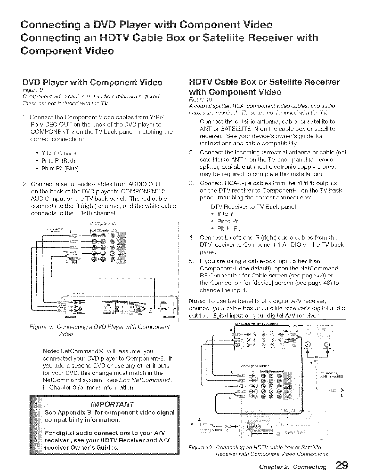
DVD Player with Component Video
Figure 9
Component video cables and audio cables are required,
Theseare not included with the TV,
1. Connect the Component Video cables from _r;IPri
Pb VIDEO OUT on the back of the DVD player to
COMPONENT-2 on the TV back pane[, matching the
correct connection:
Y to Y (Green)
Pr to Pr (Red)
Pb to Pb (Blue)
2. Connect a set of audio cables from AUDIO OUT
on the back of the DVD player to COMPONENT-2
AUDIO Input on the TV back panel The red came
connects to the R (right) channel and the white came
connects to the L ([eft) channel
Figure 9. Connecting a DVD Player with Component
Video
Note: NetCommand@ wiil assume you
connected your DVD player to Component-2. If
you add a second DVD or use any other inputs
for your DVD, this change must match in the
NetCommand system. See Edit NetCommand...
in Chapter 3 for more information.
HDTV Cable Box or Satellite Receiver
with Component Video
Figure 10
A coaxial splitter, RCA component video cables, and audio
cables are required, Theseare not included with the T_/:
1. Connect the outside antenna, cable, or satellite to
ANT or SATELUTE IN on the came box or satellite
receiver. See your device's owner's guide for
instructions and came compatibility.
2. Connect the incoming terrestrial antenna or cable (not
satellite) to ANT-1 on the TV back pane[ (a coaxial
splitter, available at most electronic supply stores,
may be required to complete this installation).
3. Connect RCA-type cables from the YPrPb outputs
on the DTV receiver to Component-1 on the TV back
pane[, matching the correct connections:
DTV Receiver to TV Back pane[
YtoY
, Pr to Pr
Pb to Pb
4. Connect L ([eft) and R (right) audio cables from the
DTV receiver to Component-1 AUDIO on the TV back
panel
5. If you are using a cable-box input other than
Component-1 (the ddau[t), open the NetCommand
RF Connection for CaMe screen (see page 49) or
the Connection for [device] screen (see page 48) to
change the input.
Note: To use the benefits of a digital A/V receiver,
connect your cable box or satellite receiver's digital audio
out to a digital input on your digital AiV receiver.
DI_ [1ec ei_J_ {with yF_pb c onne_tio_)
2.
4-- _:_i _ _ _...._
II/coming AntEJnna 2.
or CabiD
Figure I0. Connecting an HDTV cable box or Satellite
Receiver with Component Video Connections
Chapter2. Connecting 29
Connecting an HDM[ or DV[ Device
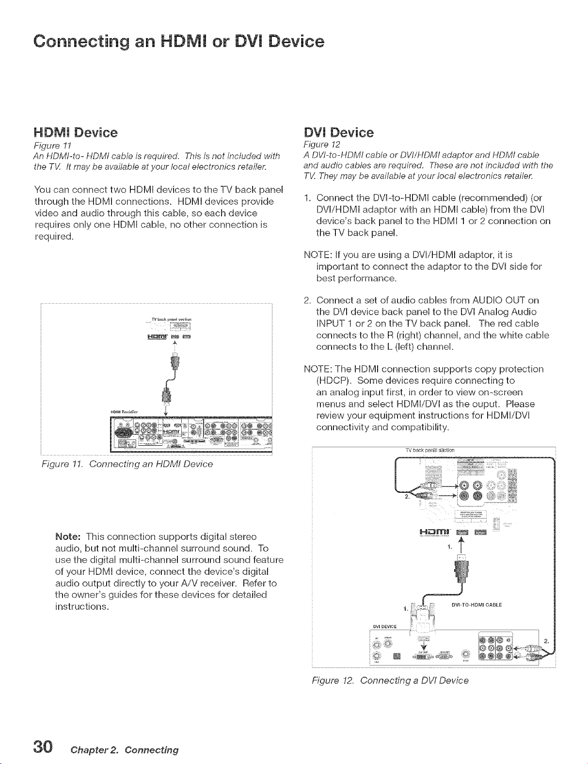
HDM[ Device
Figure 11
An HDMI-to- HDMI cable is required. This is not included with
the TV. /t may be available at your local electronics retailer.
You can connect two HDM[ devices to the TV back pane[
through the HDM[ connections. HDM[ devices provide
video and audio through this cable, so each device
requires only one HDM[ cable, no other connection is
required_
TV back pa_e_ _tie,_
Figure 11. Connecting an HDM/ Device
DV[ Device
Figure 12
A DVI-to-HDMI cable or DV//HDMI adaptor and HDMI cable
and audio cables are required. These are not included with the
TV. They may be available at your local electronics retaile,c
1_ Connect the DV[-to-HDM[ cable (recommended) (or
DV[iHDM[ adaptor with an HDM[ cable) from the DV[
device's back pane[ to the HDM[ 1 or 2 connection on
the TV back panel
NOTE: If you are using a DV[iHDM[ adaptor, it is
important to connect the adaptor to the DV[ side for
best performance.
2. Connect a set of audio cables from AUDIO OUT on
the DV[ device back panel to the DV[ Analog Audio
INPUT 1 or 2 on the TV back panel. The red cable
connects to the R (right) channel, and the white cable
connects to the L (left) channel.
NOTE: The HDM[ connection supports copy protection
(HDCP). Some devices require connecting to
an analog input first, in order to view on-screen
menus and select HDM[/DV[ as the oupuL Please
review your equipment instructions for HDM[iDV[
connectivity and compatibility.
"]_/back panB[ s_ct[on
Note: This connection supports digital stereo
audio, but not multi-channel surround sound. To
use the digital multi-channel surround sound feature
of your HDM[ device, connect the device's digital
audio output directly to your AiV receiver. Refer to
the owner's guides for these devices for detailed
instructions.
L .......................
F T ' _ ' /
Figure 12. Connecting a DW Device
30 Chapter 2. Connecting
Connecting the IR Emitter NetCommand ®
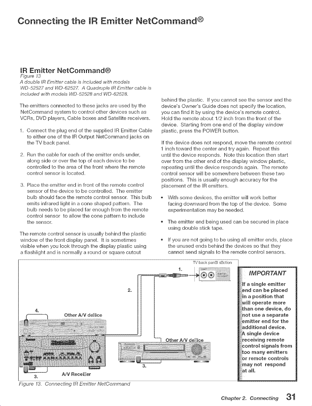
IR Emitter NetCommand®
Figure 13
A double IR Emitter cable is included with models
WD+52527 and WD-62527. A Quadruple/R Emitter cable is
included with models WD-52528 and WD+62528.
The emitters connected to these jacks are used by the
NetCommand system to controH other devices such as
VCRs, DVD pHayers, CabHe boxes and SateHHitereceivers+
1+ Connect the pHugend of the suppHied IR Emitter CabHe
to either one of the IR Output NetCommand jacks on
the TV back panel
2+ Run the came for each of the emitter ends under,
aHong side or over the top of each device to be
controHHedto the area of the front where the remote
controH sensor is Hocated+
3+ PHacethe emitter end in front of the remote controH
sensor of the device to be controHHed+The emitter
buHb shouHd face the remote controH sensor. This buHb
emits infrared Hightin a cone shaped pattern+ The
buHb needs to be pHaced far enough from the remote
controH sensor to aHHowthe cone pattern to incHude
the sensor+
The remote controH sensor is usuaHHybehind the pHastic
window of the front dispHay panel It is sometimes
visibHe when you Hook through the dispHay pHastic using
a fHashHightand is normaHHya round or square cutout
2,
4,
Other A/V de_ice
3. A/V Recei[:_er
Figure 13. Connecting/R Emitter NetCommand
behind the pHastic. If you cannot see the sensor and the
device's Owner's Guide does not specify the Hocation,
you can find it by using the device's remote control
HoHdthe remote about 1/2 inch from the front of the
device+ Starting from one end of the dispHay window
pHastic, press the POWER button+
If the device does not respond, move the remote controH
1 inch toward the center and try again+ Repeat this
untiHthe device responds. Note this Hocation then start
over from the other end of the dispHay window pHastic,
repeating untiHthe device responds again. The remote
controH sensor wiHHbe somewhere between these two
positions. This is usuaHHyenough accuracy for the
pHacement of the IR emitters+
+ With some devices, the emitter wiHHwork better
facing downward from the top of the device+ Some
experimentation may be needed+
+ The emitter end being used can be secured in pHace
using doubHe stick tape+
If you are not going to be using aHHemitter ends, pHace
the unused ends behind the devices so that they
cannot send signaHs to the remote controH sensors+
TV back panBI sBction
1 I !
++7 Other A/V de[_ice
3,
n a position that
_ili operate more
:hart one device, do
not use a separate
emitter end for the
additional device,
A single device
receiving remote
control signals from
:oo many emitters
r remote controls
"nay not respond
_t aim.
Chapter 2. Connecting
Connecting Compatible IEEE 1394 Devices
CompatibJe IEEE 1394 Devices
It is possible to connect devices to the TV that have IEEE
1394connectors but are not compatible with the TV or with
the NetCommand ® control system. Areas of compatibility to
consider are:
1. Digital Video Signals
The TV is able to decode MPEG2 video. Other types
of digital video, such as DV video provided by some
camcorders+ must be decoded by the source device
and sent to the TV as analog video or S=Video+ tf the
camcorder uses a compatible digitat control system, the
EEE 1394 cable can still provide control for the camcorder
while the TV is viewing the analog video or S=Video signals.
2. Digital Audio Signals
When received with video signals, the TV is able to decode
Dolby Digital signals and MPEG audio signals. Other types
of digital audio as provided by some digitat recording
devices, such as MP3 audio and DTS audio, cannot be
decoded by the TV when received over EEE 1394.
The TV may not be able to pass incompatible digital audio
signals on the coaxia! digitat audio output, however these
signals may pass on the EEE 1394 cable to other devices.
3. Digital Control Signal
The TV is able to act as the control center for EEE 1394
audio/video devices, such as VCRs, A/V Discs, tuners,
cable boxes and amplifiers that are compatible with the
following EEE 1394 control standards.
EIA°775 is designed for tuning devices such as cable
boxes allowing the device to send simple graphics.
However, this standard does not allow the TV to control
the cable box by IEEE 1394+
® AV/C {Audio Video Contro+) is designed to provide
basic controls such as play, stop, channel selection and
volume, as appropriate for the device+
Some devices may be a combination of two or more
types of devices. For example, there may be a
recording device that is also a tuning device+ Each
portion of the device is called a sub-uniL When you
select a device on the Device Selection menu that has
sub-units, a pop-up menu will appear so you can select
which sub-unit section you wish to use+
When Connecting IEEE 1394 Devices
+ Do not loop the last device in the chain back to the
TW When the device chain is looped, the TV may
not be able to work with the other devices+
Place devices that have only a mechanical (two-
position) power switch at the end of the chain or
leave the power switch in the On position. When
turned Off, IEEE 1394 signals may not be able to
pass through the device to other devices+
Place devices with the slowest communication
speed at the end of the chain+ Sometimes the
communication speed will be marked near the
IEEE 1394 connector with an "S" number+ The
higher the number, the faster the communication
speed+ This TV has a communication speed of
$400+ Devices with slow communication speed
can interfere with IEEE 1394 signals from faster
devices+ When using NetCommand to set up
a digital recording between a faster and slower
device, select "Record Later+"
+ Do not use an IEEE 1394 cable longer than 15 feet
between each device+
This TV is an IEEE 1394a Device+ IEEE 1394b
is currently under development. This system
will provide for longer distances and multi-room
applications, included in the IEEE 1394b systems
are IEEE 1394a to IEEE 1394b converters to
maintain compatibility with this TV and other IEEE
1394a devices+
32 Chapter 2. Connecting
Connecting Compatible JEEE 1394 Devices, continued
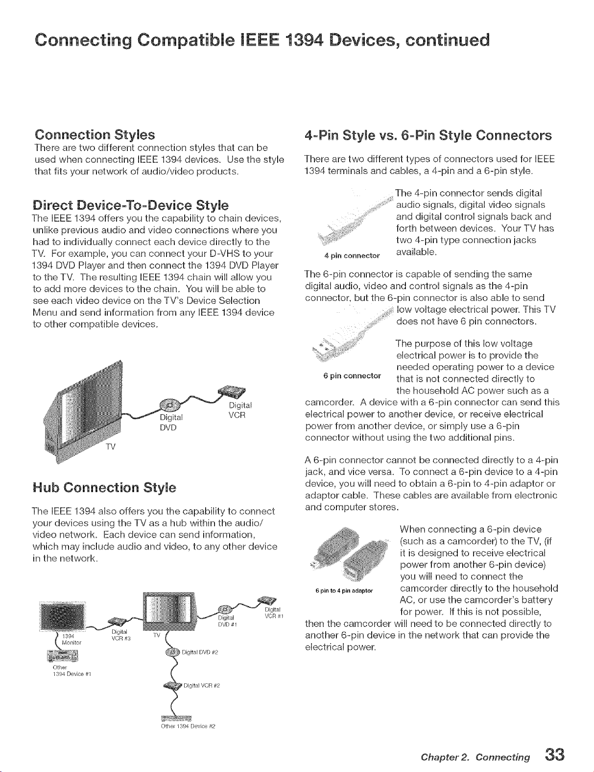
Connection Styles
There are two different connection sues that can be
used when connecting IEEE 1394 devices. Use the sue
that fits your network of audio/video products.
4-Pin Styme vs. (}-Pin Style Connectors
There are two different types of connectors used for IEEE
1394 terminaUs and cabbs, a 4-pin and a 6-pin styb.
Direct Device-To-Device Style
The BEEE1394 offers you the capabiiity to chain devices,
uniike previous audio and video connections where you
had to individually connect each device directly to the
TV. For example, you can connect your D-VHS to your
1394 DVD Player and then connect the 1394 DVD Player
to the TV. The resulting IEEE 1394 chain will allow you
to add more devices to the chain. You will be able to
see each video device on the TV's Device Selection
Menu and send information from any IEEE 1394 device
to other compatible devices.
TV
Digital
DVD
Digital
VCR
Hub Connection Style
The IEEE 1394 also offers you the capability to connect
your devices using the TV as a hub within the audio/
video network. Each device can send information,
which may include audio and video, to any other device
in the network.
1394
Monitor
Other
1394 Device #1
Digital
VCR #3
DVD #1
TV
) Digital DVD #2
Digital VCR #2
Digital
VCR #1
4 pin connector available.
The 6-pin connector is capable of sending the same
digital audio, video and control signals as the 4-pin
connector but the 6-pin connector is also able to send
low voltage electrical power. This TV
does not have 6 pin connectors.
The purpose of this low voltage
electrical power is to provide the
needed operating power to a device
6 pin connector that is not connected directly to
the household AC power such as a
camcorder. A device with a 6-pin connector can send this
electrical power to another device, or receive electrical
power from another device, or simply use a 6-pin
connector without using the two additional pins.
A 6-pin connector cannot be connected directly to a 4-pin
jack, and vice versa. To connect a 6-pin device to a 4-pin
device, you wiii need to obtain a 6-pin to 4-pin adaptor or
adaptor cable. These cables are available from electronic
When connecting a 6-pin device
(such as a camcorder) to the TV, (if
it is designed to receive electrical
power from another 6-pin device)
you will need to connect the
6pinto4pinadaptor camcorder directly to the household
AC, or use the camcordePs battery
for power. If this is not possible,
then the camcorder will need to be connected directly to
another 6-pin device in the network that can provide the
electrical power.
Other 1394 Device #2
Chapter2. Connecting 33
Connecting: Helpful Hints
Q, My VCR (or other device} does not have two sets of stereo audio outputs, How can I connect this
device's audio to both the TV and the A/V Receiver?
A, Connect the single set of stereo audio outputs to the TV onHy. Use Edit NetCommand® to change the setup of this
device. In the Connection screen of "Change" make sure both audio and video for the TV input are check marked
and neither the audio or the video for the AVR input are check marked. This will allow the NetCommand system to
use the TV outputs to transfer the device's audio to the AiV Receiver. See Edit NetCommand in the next chapter for
details.
Q. I have both the TV stereo audio output and TV digital audio output connected to the same input
designations on my A/V Receiver, How do I switch between analog audio and digital audio?
A. In most setups, analog audio is also output as digital audio, so no switching is required, and there is no need to
connect the analog output. In some circumstances, however, you may also need analog audio from the TV. For
example, MP3 audio is only output in analog format, so you must connect the TV's analog AUDIO OUTPUT to the
AiV Receiver if you want it to play MP3 audio. Refer to your AiV Receiver user's guide to find out how analog/
digital audio switching works.
If your AiV Receiver's remote control has an Analog/Digital Audio key, you can use the GUIDE key with the
following models to control switching:
Mitsubishi M-VR900 Integra DTR-9J
Denon AVR-2700 Kenwood VR-2080
To make the switch, press the Device key on the TV's remote control, and from the Device Selection menu,
press the Audio key. Then, with the AiV Receiver highlighted, press the GUIDE key to make the switch.
If you have some other A/V Receiver model, use the TV's learn function to learn the code for the GUIDE key.
Follow the instructions above for using the GUIDE key.
If your AiV Receiver has an Analog/Digital selection key on the front panel only, and not on the remote, then
your only option is to use that key to perform switching.
Q, The front panel of my A/V Receiver is too tall or too convex for the IR emitter signal to reach the remote
control sensor of the A/V Receiver, What can I do?
A. There are several possible solutions.
1_ Mount the IR Emitter on the top, front edge of the AiV Receiver over the remote control sensor. Use tape to
secure it in place.
2_ Mount the IR Emitter on the underside of the shelf above the AiV Receiver (if the AiV Receiver is in a cabinet).
Use double sided tape to secure it in place.
3_ Some small stick-on emitters from other manufacturers may be compatible with this TV's IR Emitter jacks. These
may be used instead of the supplied IR Emitters.
Q, I occasionally need to see the menu from my A/V Receiver, How can I connect it to the TV for this
purpose?
A. You can connect the video output of the AiV Receiver to an unused input on the TV. Then use Edit NetCommand to
"Add" this as an "Other" device, not an A/V Receiver. On the "Connection" screen, indicate which TV input was used
and check mark the video box. Make sure the TV input audio box and both the audio and video boxes for the AVR
input are not check marked. You should also name this device so you can easily identify it on the Device Selection
Menu. You can also use Input 3 (Camcorde0 on the front panel.
Q. I have a high definition receiver I would like to connect and it also has an S-video output I would like
to be able use as well, is there any way to connect this receiver both ways?
A. Yes, this item will appear twice in the Device Selection Menu. Just add this unit once using the Component-1 and
once using one of the S-video inputs. Make sure you indicate that this is the same manufacturer for both. We
suggest that you connect stereo audio outputs with the S-video to the TV so that you do not need to use two inputs
on the A/V Receiver. If this is a NetCommand compatible HDTV receiver and HD or SD outputs can be switched by
remote control, see Edit NetCommand in the next chapter for NetCommand control of this feature.
34 Chapter 2. Connecting
:up and Editing
NetCommand@ introduction ................................................................ 36
Using the Remote Control with NetCemmand@ ................................ 37
NetCommand@ Setup On-Screen Buttons .......................................... 38
3D GraphicaU Viewpoint@ Menu System ............................................... 39
NetCommand@ JnitiaU Setup .................................................................. 40
Edit NetCommand@
Add an A/V Receiver ......................................................................... 43
Add Devices ....................................................................................... 46
Change Devices ................................................................................ 50
DeUete Devices ................................................................................... 50
Finish Screen ..................................................................................... 50
NetCommand® Introduction
Welcome To NetCommand!
NetCommand makes your TV the heart of your Home Theater
NetCommand@ is an intelligent controU system that allows your Mitsubishi TV to become the heart of your Home
Theater. With NetCommand, the TV sends signals to the other devices in the system, telling them to play, record,
change inputs, adjust volume, change channels and many more functions. All of this is accomplished with one remote
control and without changing control layers.
IR Learning and IEEE 1394 Support
The "JR Learning" feature of NetCommand allows the TV to barn the remote control signals for new devices that the TV
is not preprogrammed to operate. NetCommand@ also includes the capability to control IEEE 1394 devices by sending
control signals on a FireWire@ cable.
Using HetCommand is completely optional
When you first turn on the TV, the NetCommand Setup Wizard launches. If you decide to use NetCommand, follow
the on-screen instructions, if you choose not to use it right away, simply quit the Setup Wizard and NetCommand wiii
remain inactive. Later, if you decide to use NetCommand, you can easily access the Setup Wizard.
HetOommand and Levels of Control
When you set up NetCommand, you decide how much control you want the TV to have over your home theater system.
You have the choice of performing a basic, limited, or complete NetCommand setup.
Basic Setup
In a basic setup, NetCommand will:
§ automatically switch to the correct TV input when you want to view programming from a different device. All
you do is select the device from the on-screen device selection menu. This saves you from having to search
for the correct input every time you want to change devices. Unused inputs are automatically deactivated so
that you don't see them in the menu.
§ show an on-screen icon for each device connected to the TV so you always know what devices are available.
Note that with a basic setup, you still need to use the remote control specific to each device.
Limited Setup
In a limited setup, you get the benefits of the basic setup plus NetCommand control over the specific devices you
have chosen. Use this type of setup if you:
§ only want NetCommand to control a few devices, such as the TV, a playback device (like a DVD player), and a
cable box. With this setup, you can use the TV's remote to control these devices.
§ want to use TV Guide On Screen@ to control your cable box, VCR, or AiV disc. After performing this setup,
you can use the TV's remote to control the device.
Full Setup
Perform a full setup if you want NetCommand to:
§ control a surround sound AiV receiver.
§ automatically change input selections for the AiV receiver.
§ control all devices with the TV's remote, including the AiV receiver.
HetOommand Helps You Manage Your Home=Theater Connections
With the NetCommand Review screen you can:
view a summary of all devices connected to the TV and the input used for each device.
deactivate or turn off unused input connections.
If you need to change your setup, a NetCommand sub-menu lets you easily
add new devices.
deleted devices you have disconnected.
change device and input selections.
3_ Chapter 3. NetCommand Setup and Editing
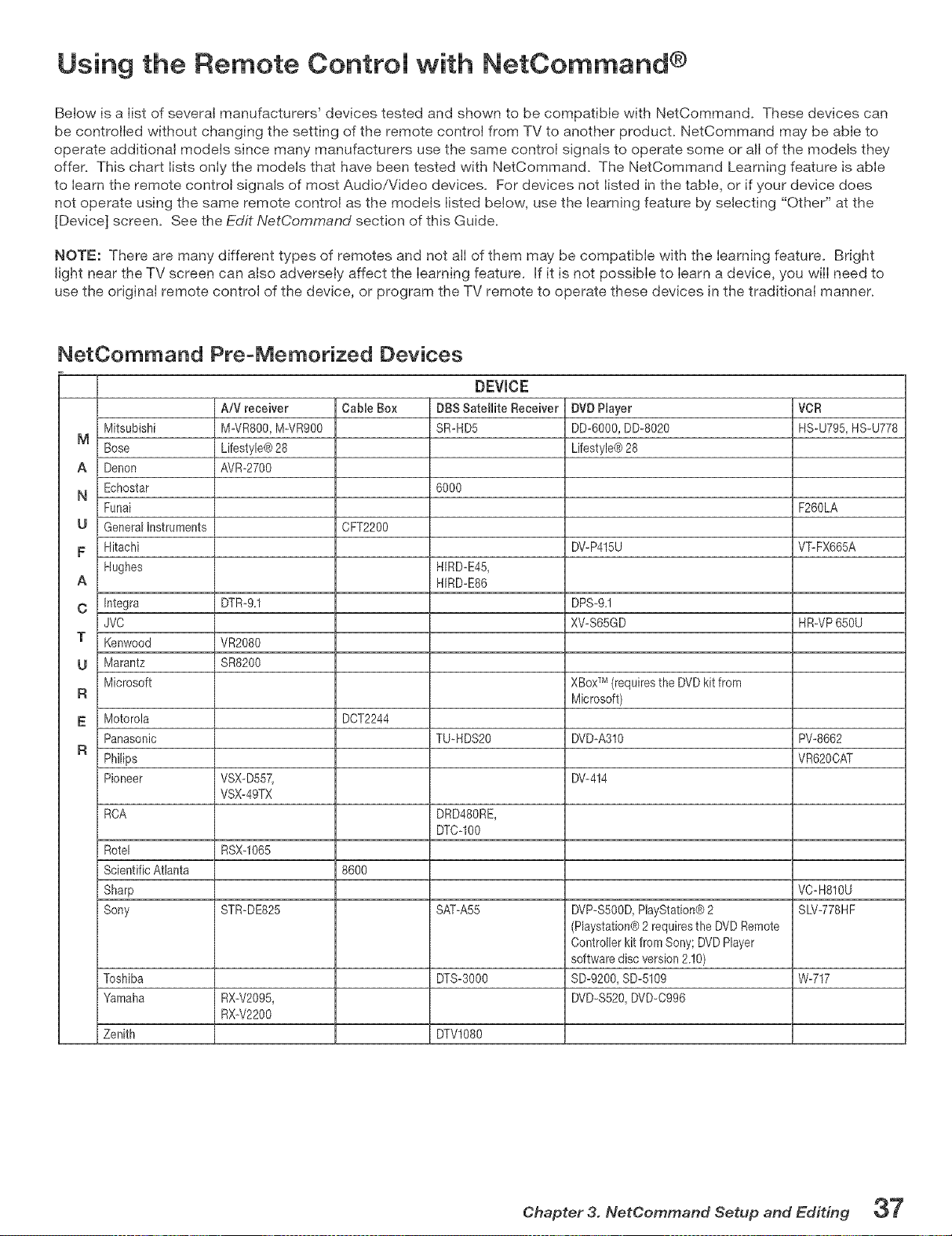
Using the Remote Control with NetCommand ®
Below is a Iist of several manufacturers' devices tested and shown to be compatible with NetCommand. These devices can
be controlled without changing the setting of the remote control from TV to another product. NetCommand may be able to
operate additional models since many manufacturers use the same control signals to operate some or all of the models they
offer. This chart lists only the models that have been tested with NetCommand. The NetCommand Learning feature is able
to learn the remote control signals of most Audio/Video devices. For devices not listed in the table, or if your device does
not operate using the same remote control as the models listed below, use the learning feature by selecting "Other" at the
[Device] screen. See the Edit NetCommand section of this Guide.
NOTE: There are many different types of remotes and not all of them may be compatible with the learning feature. Bright
light near the TV screen can atso adversely affect the learning feature. If it is not possible to learn a device, you will need to
use the original remote control of the device, or program the TV remote to operate these devices in the traditionaI manner.
NetOommand PreoMemorized Devices
DEVICE
A/V receiver Cable Box DBSSatellite Receiver DVDPlayer VCR
Mitsubishi M-VR800,M-VR900 SR-HD5 DD-6000,D%8020 HS-U795,HS_U778
M
Hose Lifestyle®28 Lifestyle®28
A Denon AVR-2700
Echostar 6000
N
Funai F260LA
U GeneralInstruments CFT2200
F Hitachi DWP415U VT_FX665A
Hughes HIRD_E45,
A HIRD_E86
O Integra DTR-9.1 DPS-9.1
JVC XV-S65GD HR_VP650U
T Kenwood VR2080
U Marantz SR8200
Microsoft XBoxTM (requiresthe DVDkit from
R Microsoft)
_: Motorola DOT2244
Panasonic TU_HDS20 DVD_A310 PV_8662
R
Philips VR620CAT
Pioneer VSX_D557, DV_414
VSX_49TX
RCA DRD480RE,
DTO_100
Rotel RSX_1065
ScientificAtlanta 8600
Sharp VO_H810U
Sony STR_DE825 SAT_A55 DVP_S500D,PlayStation@2 SLV_778HF
(Playstation®2 requiresthe DVDRemote
Controllerkit fromSony;DVDPlayer
softwarediscversion2.10)
Toshiba DTS_3000 SD_9200,SD_5109 %717
Yamaha RX_V2095, DVD_S520,DVD_O996
RX_V2200
Zenith DTVl080
Chapter 3. NetCemmand Setup and Editing 37
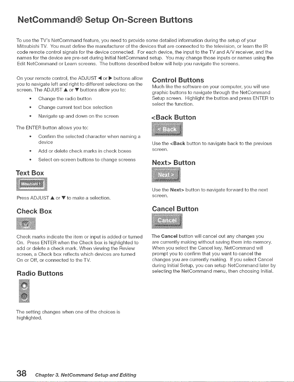
NetCommand® Setup OnoScreen Buttons
To use the TV's NetCommand feature, you need to provide some detaibd information during the setup of your
Mitsubishi TV. You must define the manufacturer of the devices that are connected to the tebvision, or barn the IR
code remote controi signais for the device connected. For each device, the input to the TV and AiV receiver, and the
names for the device are pre-set during Initiai NetCommand setup. You may change those inputs or names using the
Edit NetCommand or Learn screens. The buttons described bellow will heip you navigate the screens.
On your remote control, the ADJUST 4 or _ buttons allow
you to navigate left and right to different selections on the
screen. The ADJUST _ or _' buttons allow you to:
Change the radio button
o Change current text box selection
Navigate up and down on the screen
The ENTER button allows you to:
Confirm the selected character when naming a
device
Add or delete check marks in check boxes
Select on-screen buttons to change screens
Text Box
ControJ Buttons
Much Hikethe software on your computer, you will use
graphic buttons to navigate through the NetCommand
Setup screen. Highlight the button and press ENTER to
select the function.
<Back Button
Use the <Back button to navigate back to the previous
screen.
Next> Button
Press ADJUST A or Y to make a selection.
Check Box
Use the Next> button to navigate forward to the next
screen,
Cancel Button
Check marks indicate the item or input is added or turned
On. Press ENTER when the Check box is highlighted to
add or delete a check mark. When viewing the Review
screen, a Check box reflects which devices are turned
On or Off, or connected to the TV.
Radio Buttons
The Cancel button wiii cancel out any changes you
are currently making without saving them into memory.
When you select the Cancel key, NetCommand will
prompt you to confirm that you want to cancel the
changes you are currently making. If you select Cancel
during Initial Setup, you can setup NetCommand later by
selecting the NetCommand menu, then choosing Initial.
The setting changes when one of the choices is
38 Chapter 3. NetCemmand Setup and Editing
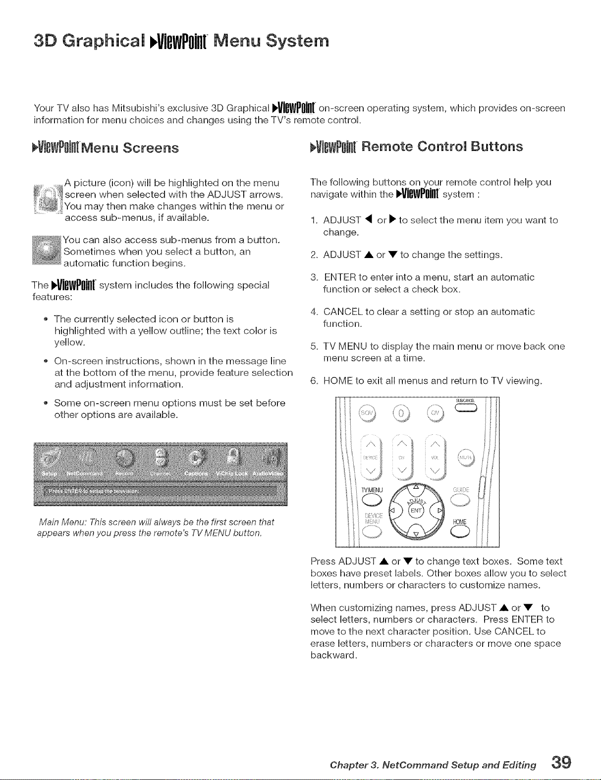
3D Graphicam l,ViewPoiillMenu System
Your TV arise has Mitsubishi's excHusive 3D GraphicaH .ViewPoilI[on-screenoperatingsystem,which provides on-screen
information for menu choices and changes using the TV's remote control
VJeWPOJntMenu Screens 'VJJ{WPOJnlRemote ControJ Buttons
access sub-menus, if avaiHabHe,
You can arise access sub-menus from a button.
Sometimes when you seHect a button, an
automatic function begins.
The I,ViewPoig[system inc.udes the following specia.
features:
• The currently selected icon or button is
highlighted with a yellow outline; the text color is
yellow.
On-screen instructions, shown in the message line
at the bottom of the menu, provide feature selection
and adjustment information.
Some on-screen menu options must be set before
other options are available.
Main Menu: This screen will always be the first screen that
appears when you press the remote's TV MENU button,
The following buttons on your remote control help you
navigate within the l,VlewPoln[system :
1. ADJUST _ or Im"to select the menu item you want to
change.
2. ADJUST A or • to change the settings.
3. ENTER to enter into a menu, start an automatic
function or select a check box.
4. CANCEL to clear a setting or stop an automatic
function.
5. TV MENU to display the main menu or move back one
menu screen at a time.
6. HOME to exit all menus and return to TV viewing.
$U_/O_OEL
Press ADJUST • or • to change text boxes. Some text
boxes have preset labels. Other boxes allow you to select
letters, numbers or characters to customize names.
When customizing names, press ADJUST • or • to
select letters, numbers or characters. Press ENTER to
move to the next character position. Use CANCEL to
erase letters, numbers or characters or move one space
backward.
Chapter 3. NetCemmand Setup and Editing 39
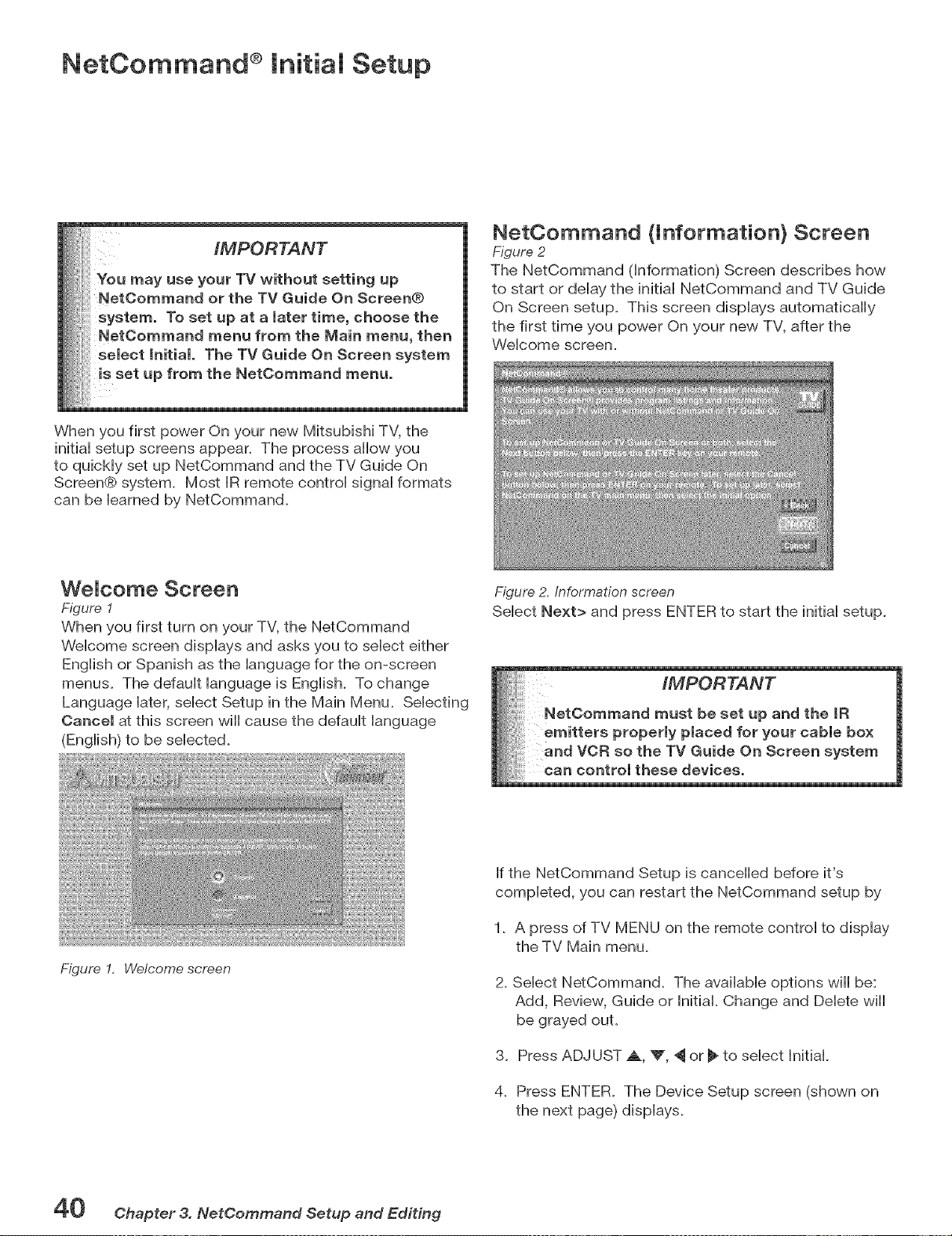
NetCommand ® lnitiam Setup
IMPORTANT
When you first power On your new Mitsubishi TV, the
initiaHsetup screens appear. The process allow you
to quicMy set up NetCommand and the TV Guide On
Screen@ system. Most IR remote controH signaHformats
can be Hearned by NetCommand.
NetOommand (information} Screen
Figure 2
The NetCommand (Information) Screen describes how
to start or delay the initial NetCommand and TV Guide
On Screen setup. This screen displays automatically
the first time you power On your new TV, after the
Welcome screen.
WeJcome Screen
Figure 1
When you first turn on your TV, the NetCommand
Welcome screen displays and asks you to select either
English or Spanish as the language for the on-screen
menus. The default language is English. To change
Language later, select Setup in the Main Menu. Selecting
Cancel at this screen will cause the default language
(English) to be selected.
Figure 2. Information screen
Select Next> and press ENTER to start the initial setup.
Figure 1, Welcome screen
If the NetCommand Setup is cancelled before it's
completed, you can restart the NetCommand setup by
1. A press of TV MENU on the remote control to display
the TV Main menu.
2. Select NetCommand. The available options will be:
Add, Review, Guide or Initial. Change and Delete will
be grayed out.
3. Press ADJUST _., V, ,_ or _ to select Initial.
4. Press ENTER. The Device Setup screen (shown on
the next page) displays.
40 Chapter 3. NetCommand Setup and Editing
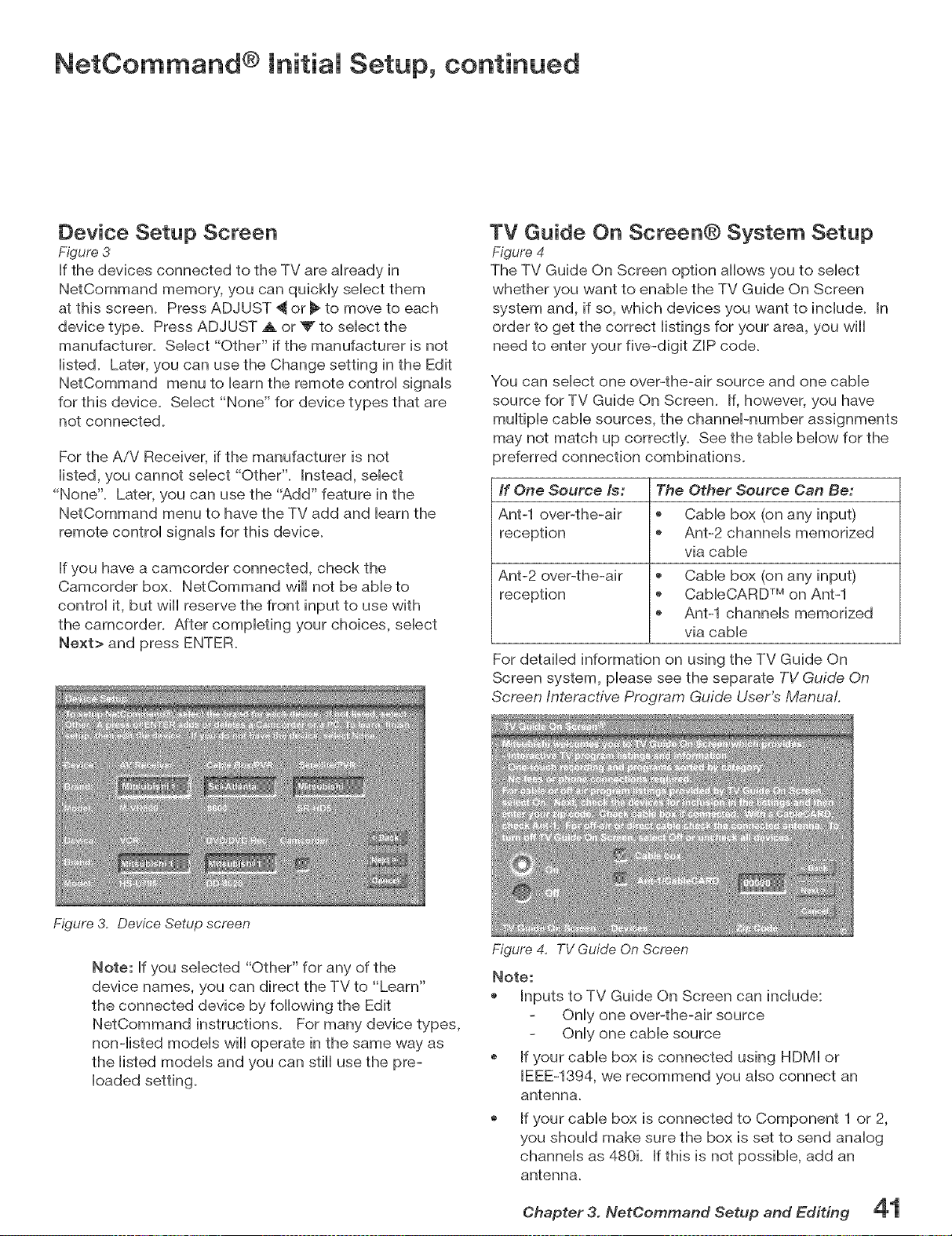
NetCommand ® initial Setup, continued
Device Setup Screen
Figure 3
If the devices connected to the TV are aiready in
NetCommand memory, you can qubMy sebct them
at this screen. Press ADJUST _ or _ to move to each
device type. Press ADJUST _ or _ to sebct the
manufacturer. Sebct "Other" if the manufacturer is not
iisted. Later, you can use the Change setting in the Edit
NetCommand menu to barn the remote controi signais
for this device. Sebct "None" for device types that are
not connected.
For the AiV Receiver, if the manufacturer is not
iisted, you cannot sebct "Other". Instead, sebct
"None". Later, you can use the "Add" feature in the
NetCommand menu to have the TV add and barn the
remote controi signab for this device.
If you have a camcorder connected, check the
Camcorder box. NetCommand will not be abb to
controi it, but will reserve the front input to use with
the camcorder. After completing your choices, select
Next> and press ENTER.
TV Guide On Screen® System Setup
Figure 4
The TV Guide On Screen option allows you to select
whether you want to enable the TV Guide On Screen
system and, if so, which devices you want to include. In
order to get the correct listings for your area, you will
need to enter your five-digit ZiP code.
You can select one over-the-air source and one cable
source for TV Guide On Screen. if, however, you have
multiple cable sources, the channePnumber assignments
may not match up correctly. See the table below for the
preferred connection combinations.
If One Source Is: The Other Source Can Be,
Ant-1 over-the-air , Cable box (on any input)
reception * Ant-2 channels memorized
via cable
Ant-2 over-the-air _ Cable box (on any input)
reception _ CableCARD TM on Ant-1
Ant-1 channels memorized
via cable
For detailed information on using the TV Guide On
Screen system, please see the separate TV Guide On
Screen Interactive Program Guide User's Manual
Figure 3. Device Setup screen
Note: If you selected "Other" for any of the
device names, you can direct the TV to "Learn"
the connected device by following the Edit
NetCommand instructions. For many device types,
non-listed models will operate in the same way as
the listed models and you can still use the pre-
loaded setting.
Figure 4, TV Guide On Screen
Note:
Inputs to TV Guide On Screen can include:
Only one over-the-air source
Only one cable source
If your cable box is connected using HDMI or
IEEE-1394, we recommend you also connect an
antenna.
If your cable box is connected to Component 1 or 2,
you should make sure the box is set to send analog
channels as 480k If this is not possible, add an
antenna.
Chapter 3. NetCommand Setup and Editing
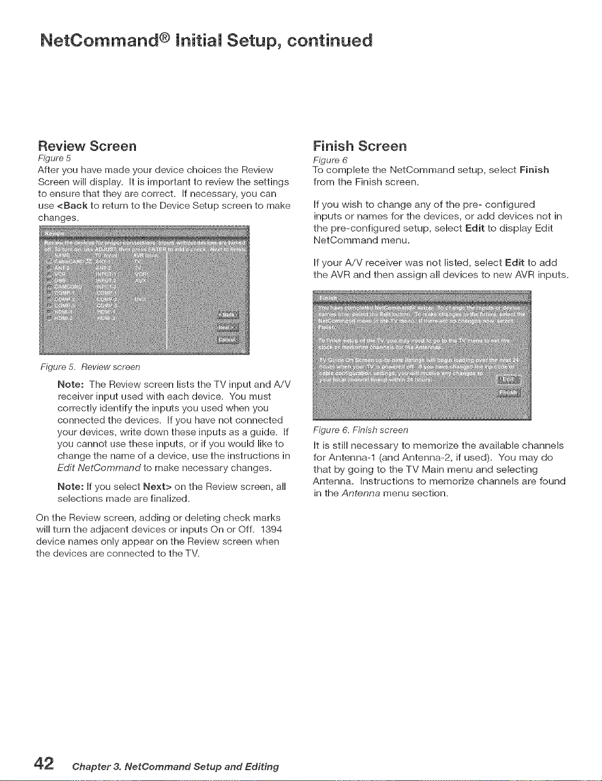
NetCommand ® Initial Setup, continued
Review Screen
Figure 5
After you have made your device choices the Review
Screen will display, it is important to review the settings
to ensure that they are correct, if necessary, you can
use <Back to return to the Device Setup screen to make
changes.
Finish Screen
Figure 6
To compbte the NetCommand setup, sebct Finish
from the Finish screen.
if you wish to change any of the pre- configured
inputs or names for the devices, or add devices not in
the pre-configured setup, sebct Edit to display Edit
NetCommand menu.
if your A/V receiver was not listed, select Edit to add
the AVR and then assign all devices to new AVR inputs.
Figure 5, Review screen
Note: The Review screen lists the TV input and AiV
receiver input used with each device. You must
correctly identify the inputs you used when you
connected the devices. If you have not connected
your devices, write down these inputs as a guide. If
you cannot use these inputs, or if you would like to
change the name of a device, use the instructions in
Edit NetCommand to make necessary changes.
Note: If you select Next> on the Review screen, all
selections made are finalized.
On the Review screen, adding or deleting check marks
wiii turn the adjacent devices or inputs On or Off. 1394
device names only appear on the Review screen when
the devices are connected to the TV.
Figure 6, Finish screen
it is still necessary to memorize the available channels
for Antenna-1 (and Antenna-2, if used). You may do
that by going to the TV Main menu and selecting
Antenna. instructions to memorize channels are found
in the Antenna menu section.
Chapter 3. NetCommand Setup and Editing
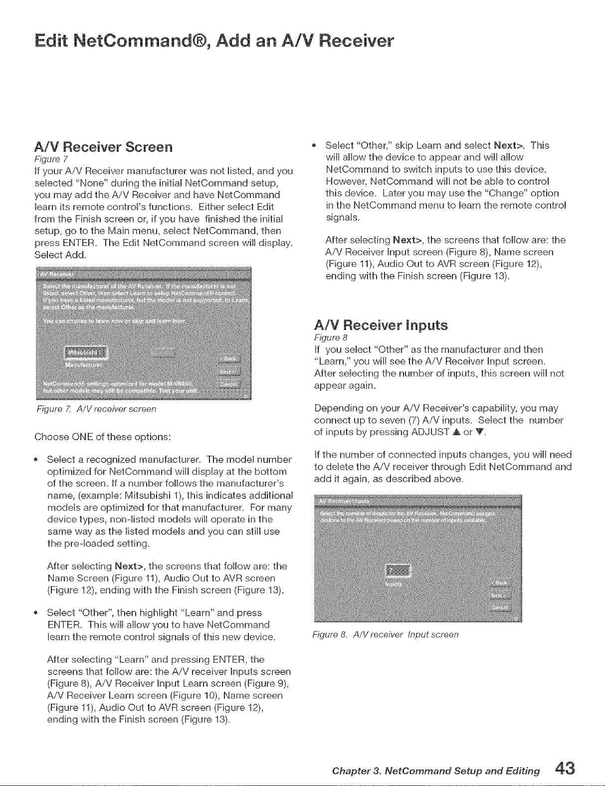
Edit NetCommand®, Add an A!V Receiver
A/V Receiver Screen
Figure 7
If your A/V Receiver manufacturer was not iisted, and you
sebcted "None" during the initiai NetCommand setup,
you may add the AiV Receiver and have NetCommand
barn its remote controFs functions. Either sebct Edit
from the Finish screen or, if you have finished the initiai
setup, go to the Main menu, sebct NetCommand, then
press ENTER. The Edit NetCommand screen will dispiay.
Sebct Add.
Figure 7. A/V receiver screen
Sebct "Other," skip Learn and sebct Next>. This
will allow the device to appear and will allow
NetCommand to switch inputs to use this devbe.
However, NetCommand will not be aMe to control
this device. Later you may use the "Change" option
in the NetCommand menu to learn the remote control
signals.
After selecting Next>, the screens that follow are: the
AiV Receiver Input screen (Figure 8), Name screen
(Figure 11), Audio Out to AVR screen (Figure 12),
ending with the Finish screen (Figure 13)_
Choose ONE of these options:
Select a recognized manufacturer. The model number
optimized for NetCommand will display at the bottom
of the screen. If a number follows the manufacturer's
name, (example: Mitsubishi 1), this indicates additional
models are optimized for that manufacturer. For many
device types, non-listed models will operate in the
same way as the listed models and you can still use
the preqoaded setting.
After selecting Next>, the screens that follow are: the
Name Screen (Figure 11), Audio Out to AVR screen
(Figure 12), ending with the Finish screen (Figure 13)_
Select "Other", then highlight "Learn" and press
ENTER. This will allow you to have NetCommand
learn the remote control signals of this new device.
After selecting "Learn" and pressing ENTER, the
screens that follow are: the AiV receiver Inputs screen
(Figure 8), A/V Receiver Input Learn screen (Figure 9),
AiV Receiver Learn screen (Figure 10), Name screen
(Figure 11), Audio Out to AVR screen (Figure 12),
ending with the Finish screen (Figure 13)_
A/V Receiver inputs
Figure 8
If you select "Other" as the manufacturer and then
"Learn," you will see the AiV Receiver Input screen.
After selecting the number of inputs, this screen will not
appear again.
Depending on your AiV Receiver's capability, you may
connect up to seven (7) AiV inputs. Select the number
of inputs by pressing ADJUST A. or V'.
If the number of connected inputs changes, you wiii need
to delete the A/V receiver through Edit NetCommand and
add it again, as described above,
Figure 8. A/V receiver input screen
Chapter 3. NetCemmand Setup and Editing 43
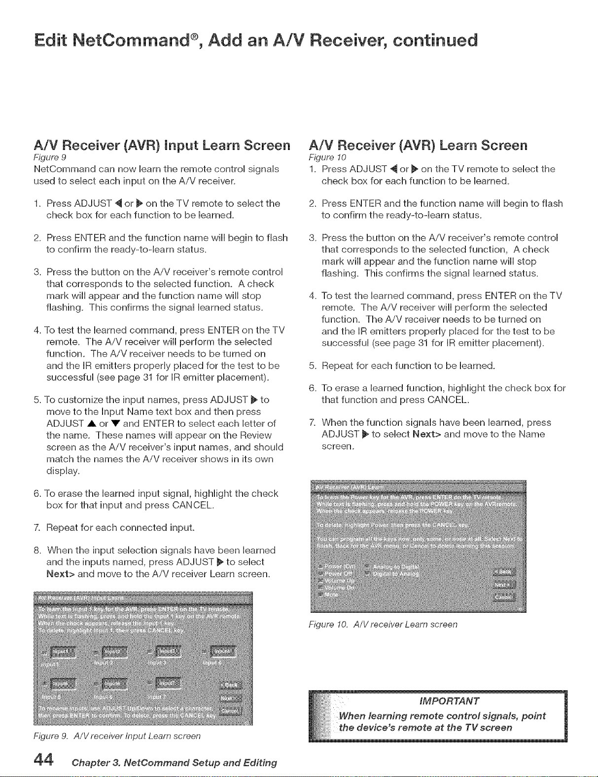
Edit NetCommand ®, Add an AiV Receiver, continued
A/V Receiver (AVR) Input Learn Screen
Figure 9
NetCommand can now barn the remote controi signab
used to sebct each input on the AiV receiver+
1. Press ADJUST _ or _ on the TV remote to sebct the
check box for each function to be bamed.
2. Press ENTER and the function name wiii begin to flash
to confirm the ready-to-learn status+
3. Press the button on the A/V receiver's remote control
that corresponds to the selected function+ A check
mark wiii appear and the function name wiii stop
flashing+ This confirms the signal learned status+
4. To test the learned command, press ENTER on the TV
remote+ The AiV receiver will perform the selected
function. The AiV receiver needs to be turned on
and the IR emitters properly placed for the test to be
successful (see page 31 for IR emitter placement).
5. To customize the input names, press ADJUST _ to
move to the Input Name text box and then press
ADJUST A or V and ENTER to select each letter of
the name+ These names will appear on the Review
screen as the AiV receiver's input names, and should
match the names the AiV receiver shows in its own
display.
6. To erase the learned input signal, highlight the check
box for that input and press CANCEL+
7. Repeat for each connected input+
8. When the input selection signals have been learned
and the inputs named, press ADJUST _ to select
Next> and move to the A/V receiver Learn screen+
Figure 9. A/Yreceiver Input Learn screen
A/V Receiver (AVR) Learn Screen
Figure 10
1. Press ADJUST _ or _ on the TV remote to select the
check box for each function to be learned.
2. Press ENTER and the function name wiii begin to flash
to confirm the ready-to-learn status+
3. Press the button on the A/V receiver's remote control
that corresponds to the selected function, A check
mark wiii appear and the function name wiii stop
flashing+ This confirms the signal learned status+
+
To test the learned command, press ENTER on the TV
remote+ The AiV receiver will perform the selected
function. The AiV receiver needs to be turned on
and the IR emitters properly placed for the test to be
successful (see page 31 for IR emitter placement).
5+ Repeat for each function to be learned.
6+ To erase a learned function, highlight the check box for
that function and press CANCEL+
7. When the function signals have been learned, press
ADJUST _ to select Next> and move to the Name
screen.
Figure 10. A/V receiver Learn screen
Chapter 3. NetCommand Setup and Editing
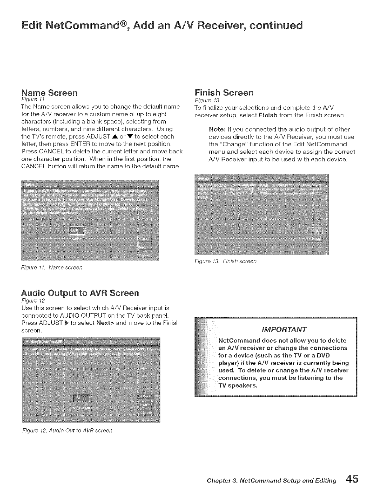
Edit NetCommand ®, Add an AiV Receiver, continued
Name Screen
Figure I1
The Name screen allows you to change the default name
for the AiV receiver to a custom name of up to eight
characters (including a blank space), selecting from
letters, numbers, and nine different characters. Using
the TV's remote, press ADJUST • or • to select each
letter, then press ENTER to move to the next position.
Press CANCEL to delete the current letter and move back
one character position. When in the first position, the
CANCEL button will return the name to the default name.
Figure 11, Name screen
Finish Screen
Figure 13
To finalize your selections and complete the A/V
receiver setup, select Finish from the Finish screen.
Note: if you connected the audio output of other
devices dkectly to the A/V Receiver, you must use
the "Change" function of the Edit NetCommand
menu and select each device to assign the correct
A/V Receiver input to be used with each device.
Audio Output to AVR Screen
Figure 12
Use this screen to select which AiV Receiver input is
connected to AUDIO OUTPUT on the TV back panel.
Press ADJUST _ to select Next> and move to the Finish
screen,
Figure 13. Finish screen
iMPORTANT
NetCommand does not allow you to delete
an A/V receiver or change the connections
for a device (such as the TV or a DVD
player} if the A/V receiver is currently being
used. To delete or change the A/V receiver
connections, you must be listening to the
TV speakers,
Figure I2, Audio Out to AVR screen
Chapter 3. NetOommand Setup and Editing 45
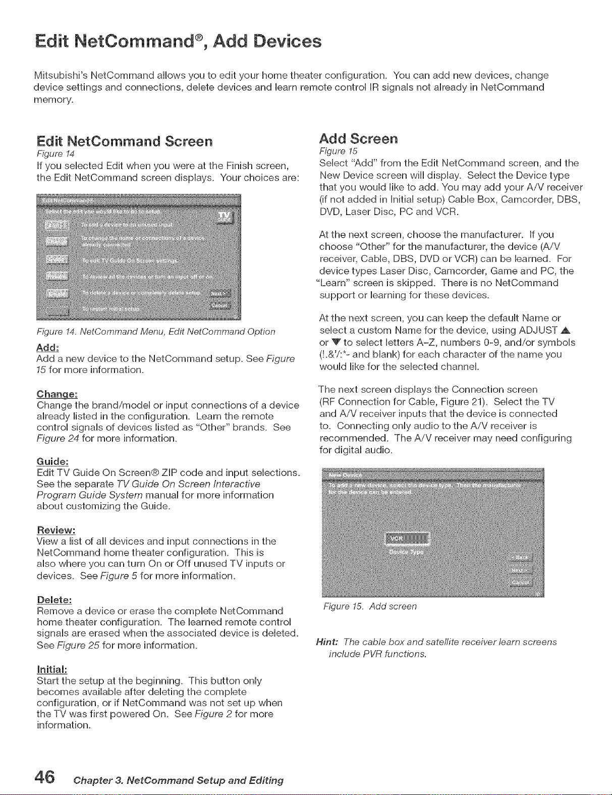
Edit NetCommand ®, Add Devices
Mitsubishi's NetCommand allows you to edit your home theater configuration. You can add new devices, change
device settings and connections, debte devices and barn remote controi IR signais not akeady in NetCommand
memory.
Edit NetCommand Screen
Figure,14
If you sebcted Edit when you were at the Finish screen,
the Edit NetCommand screen dispiays. Your choices are:
Figure,14. NetCommand Menu, Edit NetCommand Option
Add:
Add a new device to the NetCommand setup_ See Figure
15 for more information.
Change the brand/model or input connections of a device
already listed in the configuration. Learn the remote
control signals of devices listed as "Other" brands. See
Figure 24 for more information.
Guide:
Edit TV Guide On Screen® ZIP code and input selections.
See the separate TV Guide On Screen Interactive
Program Guide System manuai for more information
about customizing the Guide.
Review:
View a list of all devices and input connections in the
NetCommand home theater configuration. This is
also where you can turn On or Off unused TV inputs or
devices. See Figure 5 for more information.
Demete:
Remove a device or erase the complete NetCommand
home theater configuration. The learned remote control
signals are erased when the associated device is deleted.
See Figure 25 for more information.
initial:
Start the setup at the beginning. This button only
becomes available after deleting the complete
configuration, or if NetCommand was not set up when
the TV was first powered On. See Figure 2 for more
information.
Add Screen
Figure 15
Select "Add" from the Edit NetCommand screen, and the
New Device screen will display. Select the Device type
that you would like to add. You may add your AiV receiver
(if not added in Initial setup) Cable Box, Camcorder, DBS,
DVD, Laser Disc, PC and VCR.
At the next screen, choose the manufacturer. If you
choose "Other" for the manufacturer, the device (A/V
receiver, Cable, DBS, DVD or VCR) can be learned. For
device types Laser Disc, Camcorder, Game and PC, the
"Learn" screen is skipped. There is no NetCommand
support or learning for these devices.
At the next screen, you can keep the default Name or
select a custom Name for the device, using ADJUST ,A
or V to select letters A-Z, numbers 0-9, and/or symbols
(!.&'/:*- and blank) for each character of the name you
would like for the selected channel
The next screen displays the Connection screen
(RF Connection for Cable, Figure 21). Select the TV
and A/V receiver inputs that the device is connected
to. Connecting only audio to the AiV receiver is
recommended. The AiV receiver may need configuring
for digital audio.
Figure 15. Add screen
Hint; The cable box and sateflite receiver learn screens
include PVR functions,
46 Chapter 3. NetCommand Setup and Editing
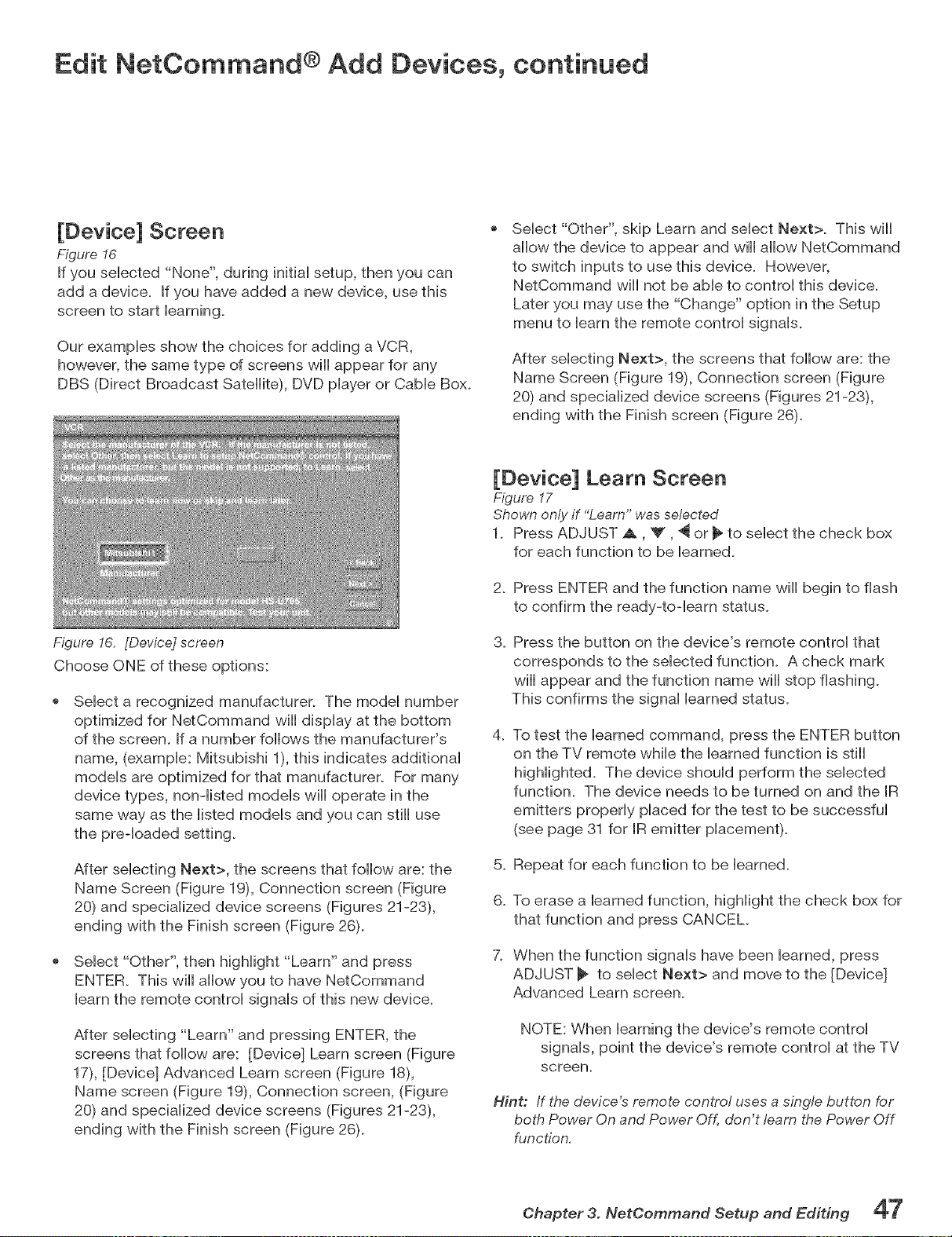
Edit NetCommand ® Add Devices, continued
[Device] Screen
Figure I6
If you sebcted "None", during initiai setup, then you can
add a device. If you have added a new device, use this
screen to start barning.
Our exampbs show the choices for adding a VCR,
however, the same type of screens will appear for any
DBS (Direct Broadcast Satellite), DVD piayer or Cabb Box.
Figure 16. [Device] screen
Choose ONE of these options:
Seiect "Other", skip Learn and sebct Next>. This will
allow the device to appear and will allow NetCommand
to switch inputs to use this device. However,
NetCommand will not be abb to controi this devbe.
Later you may use the "Change" option in the Setup
menu to barn the remote controi signais.
After sebcfing Next>, the screens that follow are: the
Name Screen (Figure 19), Connection screen (Figure
20) and specialized device screens (Figures 21-23),
ending with the Finish screen (Figure 26).
Select a recognized manufacturer. The model number
optimized for NetCommand will display at the bottom
of the screen. If a number follows the manufacturer's
name, (example: Mitsubishi 1), this indicates additional
models are optimized for that manufacturer. For many
device types, non-listed models will operate in the
same way as the listed models and you can still use
the preqoaded setting.
After selecting Next>, the screens that follow are: the
Name Screen (Figure 19), Connection screen (Figure
20) and specialized device screens (Figures 21-23),
ending with the Finish screen (Figure 26).
Select "Other", then highlight "Learn" and press
ENTER. This will allow you to have NetCommand
learn the remote control signals of this new device.
After selecting "Learn" and pressing ENTER, the
screens that follow are: [Device] Learn screen (Figure
17), [Device] Advanced Learn screen (Figure 18),
Name screen (Figure 19), Connection screen, (Figure
20) and specialized device screens (Figures 21-23),
ending with the Finish screen (Figure 26).
[Device] Learn Screen
Figure 17
Shown only if "Learn" was selected
1. Press ADJUST A, V, _ or _ to select the check box
for each function to be learned.
2. Press ENTER and the function name will begin to flash
to confirm the ready-to-learn status.
3_ Press the button on the device's remote control that
corresponds to the selected function. A check mark
will appear and the function name will stop flashing.
This confirms the signal learned status.
4_
To test the learned command, press the ENTER button
on the TV remote while the learned function is still
higHighted. The device should perform the selected
function. The device needs to be turned on and the IR
emitters properly placed for the test to be successful
(see page 31 for IR emitter placement).
5. Repeat for each function to be learned.
6. To erase a learned function, highlight the check box for
that function and press CANCEL
X When the function signals have been learned, press
ADJUST _ to select Next> and move to the [Device]
Advanced Learn screen.
NOTE: When learning the device's remote control
signals, point the device's remote control at the TV
screen.
Hint: if the device's remote control uses a single button for
both Power On and Power Off, don't learn the Power Off
function,
Chapter 3. NetOommand Setup and Editing 4mE
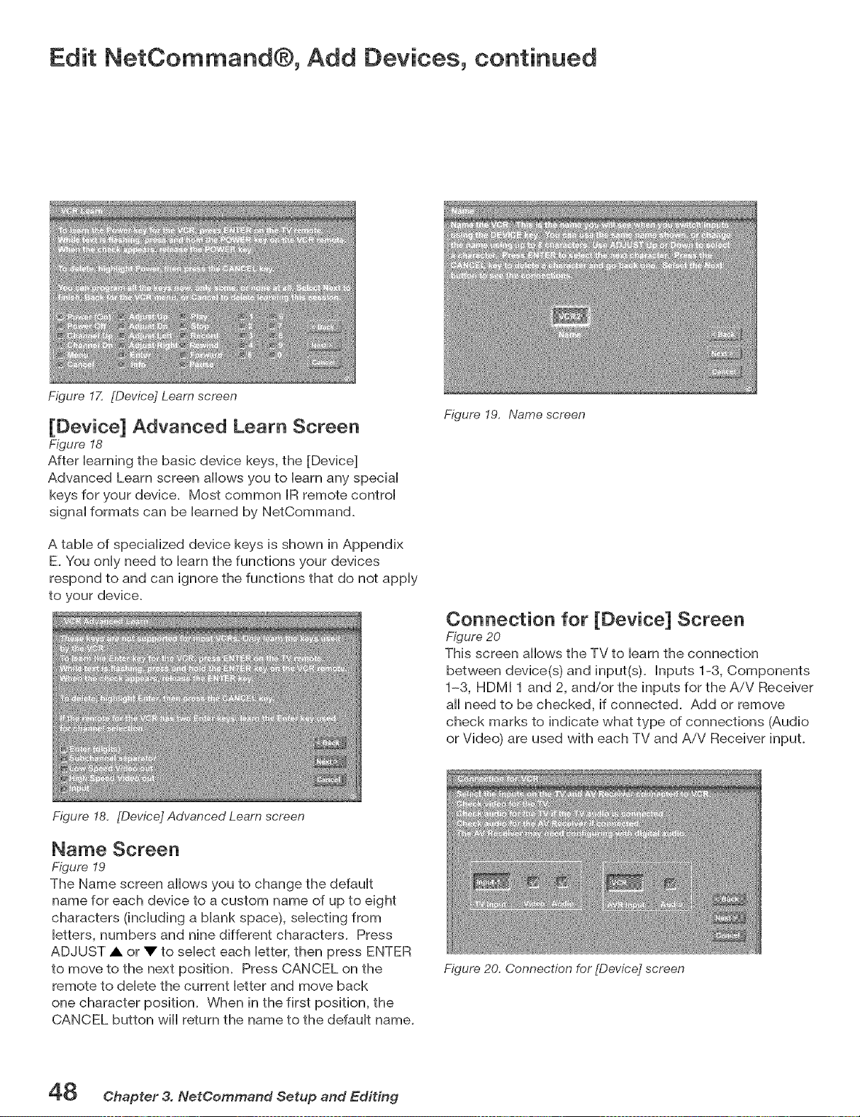
Edit NetCommand®, Add Devices, continued
Figure I7, [Device] Learn screen
[Device] Advanced Learn Screen
Figure 18
After ieaming the basic device keys, the [Device]
Advanced Learn screen aiiows you to ieam any speciai
keys for your device. Most common IR remote controi
signai formats can be ieamed by NetCommand.
A table of specialized device keys is shown in Appendix
E. You only need to learn the functions your devices
respond to and can ignore the functions that do not apply
to your device.
Figure 18, [Device] Advanced Learn screen
Figure 19, Name screen
Connection for [Device] Screen
Figure 20
This screen aiiows the TV to ieam the connection
between device(s) and input(s). Inputs 1-3, Components
1-3, HDMI 1 and 2, and/or the inputs for the AiV Receiver
aii need to be checked, if connected. Add or remove
check marks to indicate what type of connections (Audio
or Video) are used with each TV and AiV Receiver input.
Name Screen
Figure 19
The Name screen aiiows you to change the defauit
name for each device to a custom name of up to eight
characters (including a blank space), selecting from
letters, numbers and nine different characters. Press
ADJUST • or • to select each letter, then press ENTER
to move to the next position. Press CANCEL on the
remote to delete the current letter and move back
one character position. When in the first position, the
CANCEL button wiii return the name to the default name.
Figure 20. Connection for [Device] screen
48 Chapter 3. NetCommand Setup and Editing
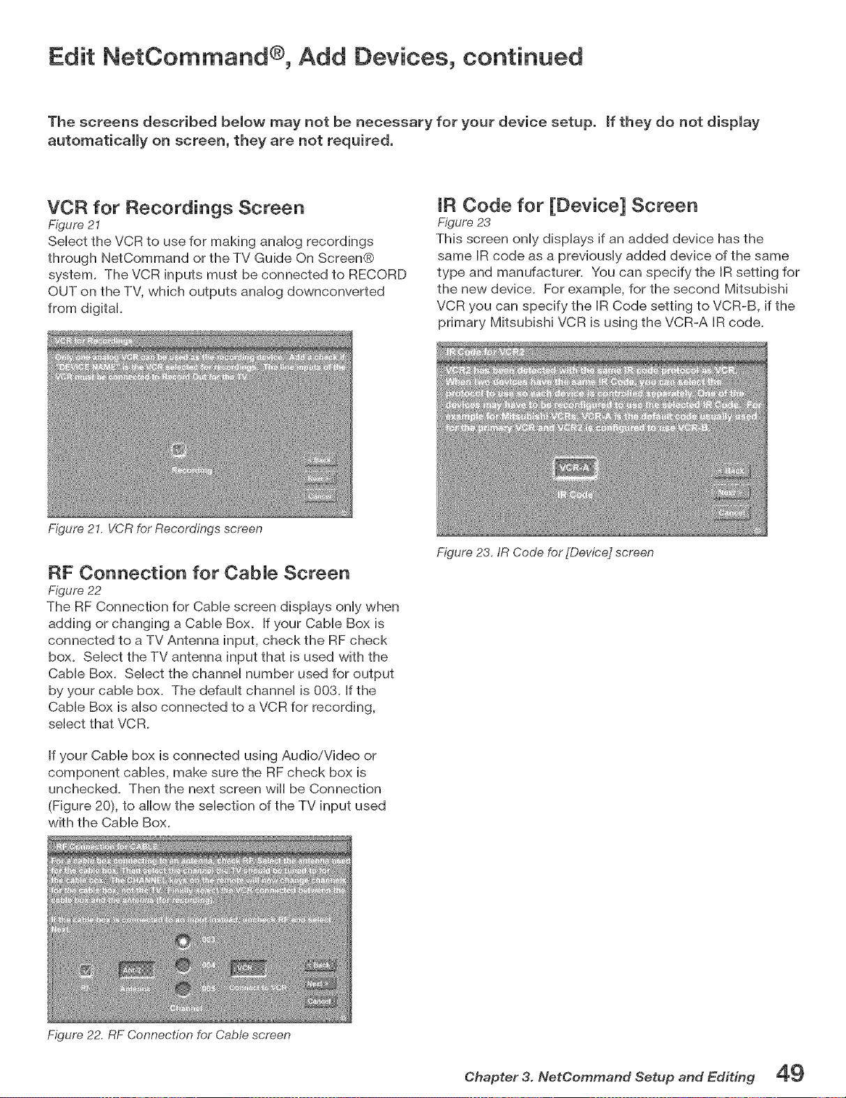
Edit NetCommand ®, Add Devices, continued
The screens described bemow may not be necessary for your device setup, mfthey do not dispmay
automatically on screen, they are not required.
VCR for Recordings Screen
Figure 21
SeHect the VCR to use for making anaHog recordings
through NetCommand or the TV Guide On Screen®
system. The VCR inputs must be connected to RECORD
OUT on the TV, which outputs anaHog downconverted
from digital
Figure 21. VCR for Recordings screen
IR Code for [Device] Screen
Figure 23
This screen only dispHays if an added device has the
same IR code as a previousHy added device of the same
type and manufacturer. You can specify the IR setting for
the new device. For exampHe, for the second Mitsubishi
VCR you can specify the IR Code setting to VCR-B, if the
primary Mitsubishi VCR is using the VCR-A IR code.
RF Connection for CabJe Screen
Figure 22
The RF Connection for Cable screen displays only when
adding or changing a Cable Box. If your Cable Box is
connected to a TV Antenna input, check the RF check
box. Select the TV antenna input that is used with the
Cable Box. Select the channel number used for output
by your cable box. The default channel is 003. if the
Cable Box is also connected to a VCR for recording,
select that VCR.
If your Cable box is connected using Audio/Video or
component cables, make sure the RF check box is
unchecked. Then the next screen will be Connection
(Figure 20), to allow the selection of the TV input used
with the Cable Box.
Figure 22. RF Connection for Cable screen
Figure 23,/R Code for[Device] screen
Chapter 3. NetOemmand Setup and Editing 49
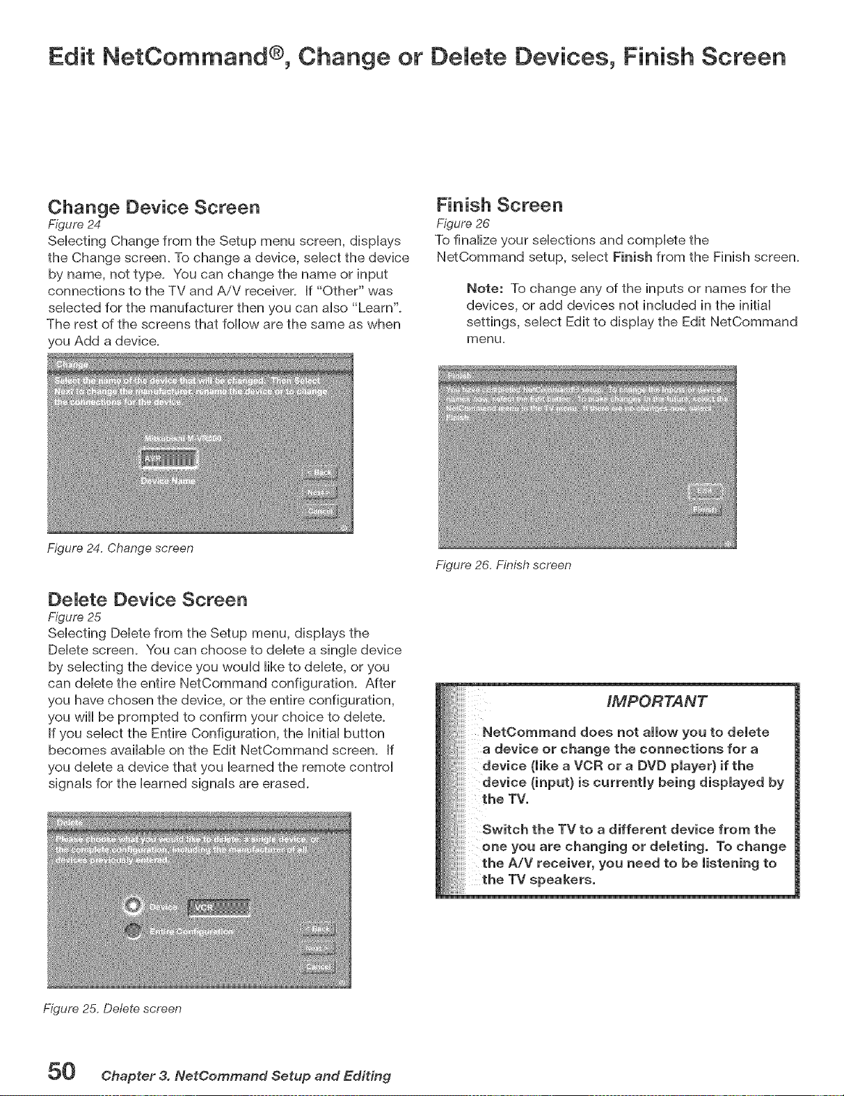
Edit NetCommand ®, Change or Demete Devices, Finish Screen
Change Device Screen
Figure 24
SeHecting Change from the Setup menu screen, dispHays
the Change screen. To change a device, seHect the device
by name, not type. You can change the name or input
connections to the TV and AiV receiver_ If "Other" was
seHected for the manufacturer then you can arise "Learn'.
The rest of the screens that follow are the same as when
you Add a device.
Figure 24. Change screen
Finish Screen
Figure 26
To finaUize your seHections and complete the
NetCommand setup, seHect Finish from the Finish screen.
Note: To change any of the inputs or names for the
devices, or add devices not incHuded in the initiaH
settings, seHect Edit to dispHay the Edit NetCommand
menu.
DeJete Device Screen
Figure 25
SeHecting DeHetefrom the Setup menu, dispHays the
Delete screen. You can choose to delete a single device
by selecting the device you would like to delete, or you
can delete the entire NetCommand configuration. After
you have chosen the device, or the entire configuration,
you will be prompted to confirm your choice to delete.
If you select the Entire Configuration, the Initial button
becomes available on the Edit NetCommand screen. If
you delete a device that you learned the remote control
signals for the learned signals are erased.
Figure 26, Finish screen
iMPORTANT
NetOommand does not allow you to delete
a device or change the connections for a
device (like a VCR or a DVD player} if the
device {input} is currently being displayed by
the TV.
Switch the TV to a different device from the
one you are changing or deleting. To change
the A/V receiver, you need to be listening to
the TV speakers.
Figure 25. Delete screen
50 Chapter 3. NetCommand Setup and Editing
IEEE 1394 Devices and NetCommand®
IEEE 1394 Devices and NetCommand® ControU .................................. 52
Adding IEEE 1394 Devices Automatically ............................................. 53
Device SeUection Menu ........................................................................... 55
Using the Device Menu Button to DispUay Menus ............................... 56
Using the GUIDE Button to DispUay ChannelView TM and Menus ........ 57
NetCommand® Controlled Peer-to-Peer Connections ...................... 58
Direct VCR Recording from an Antenna or CabUe Source .................. 59
A/V Disc Search ...................................................................................... 59
Track List Screen ................................................................................... 59
IEEE 1394 Devices and NetCommand® Control
See pages 32 and 33 for information regarding compatible IEEE 1394 devices and connection styles. The TV is not abte
to control IEEE 1394 devices that use other types of control protocols. Incompatible digital audio, video and/or control
information will still be able to pass from one device through the TV to another device on the network. These incompatible
devices may not appear on the Device Selection menu or in the Review screen of the Edit NetCommand menu.
NetOommand OontroJ of DigitaJ Devices Using the "Learn" Feature.
Some IEEE 1394 devices such as cable boxes or satellite receivers will not have compatible digital control signals or require
the use of the device's own remote control. Some of these IEEE 1394 devices will not display on=screen information through
the IEEE 1394 connection and will require using an analog connection for on=screen displays. In many cases, to control
these digitaI devices, the Learning feature of NetCommand can be used.
1. Place a connected IR Emitter in front of the device's remote control sensor (see IR Emitters, page 3I).
2. On the Name for 1394 Device screen (Figure 2, page 53) check mark the Analog Connection check box.
3. Select the device type on the IEEE 1394 Device Type screen (Figure 3, page 54) of cable box, DBS or similar tuning device.
4. Select "Other" as a manufacturer and then highlight "Learn" and press ENTER on the Device screen (Figure 4, page 53).
5. Follow the device learning instructions found in Edit NetCommand section of Chapter 3.
6. The Connection screen (Figure 5, page 54) follows the learning screens. If analog connections are used along with IEEE-
1394 connections, select the correct inputs. If analog connections are not used, uncheck the audio and video connections
for both the TV and AVR inputs.
7. Proceed with the Finish screen.
This will allow NetCommand to use the learned remote control signat to control these EEE 1394 devices.
Some cable boxes with IEEE-1394 connections use analog connections to display guides or view analog channels, and can
instruct the TV to change to the analog input. For these cable boxes, make sure you follow the instructions on pages 53 and
54 for adding analog connections for an EEE-1394 device.
Note: When using the NetCommand learning feature for IEEE 1394 devices that do not have analog connections, the
GUIDE function will require pressing GUIDE twice. The first press of GUIDE will display the TV's digital channel guide.
The second press will display the program guide for the device if an EEE 1394 Guide is available.
52 Ohapter 4. IEEE 1394 Devices and NetOommand=OontroHed Recordings
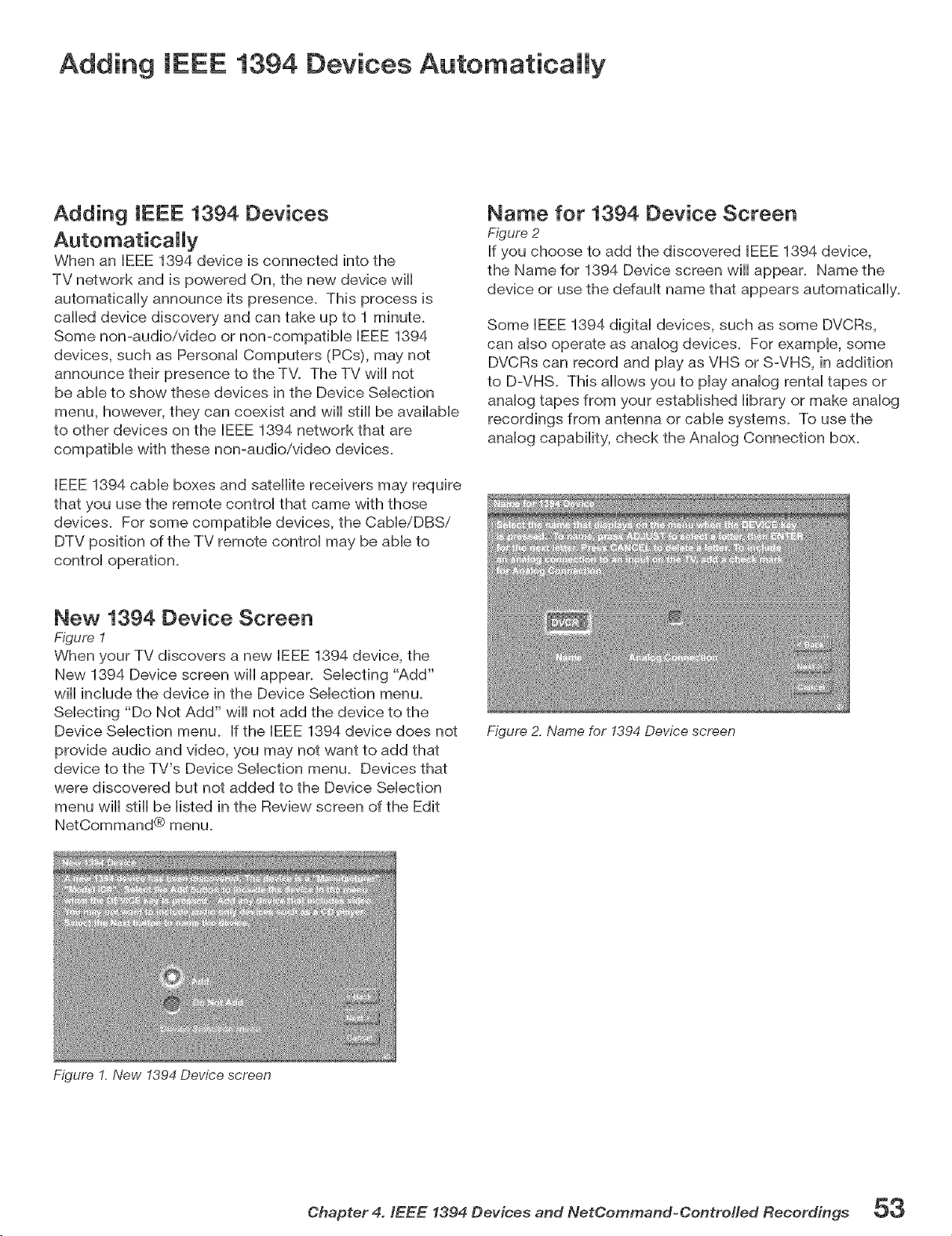
Adding IEEE 1394 Devices Automaticammy
Adding IEEE 1394 Devices
When an IEEE 1394 device is connected into the
TV network and is powered On, the new device will
automatically announce its presence. This process is
called device discovery and can take up to 1 minute.
Some non-audio/video or non-compaflMe IEEE 1394
devices, such as PersonaH Computers (PCs), may not
announce their presence to the TV. The TV will not
be aMe to show these devices in the Device SeHecfion
menu, however, they can coexist and wifl still be avaiHabHe
to other devices on the IEEE 1394 network that are
compatible with these non-audio/video devices.
IEEE 1394 cable boxes and satellite receivers may require
that you use the remote control that came with those
devices. For some compatible devices, the CableiDBSi
DTV position of the TV remote control may be able to
control operation.
Name for 1394 Device Screen
Figure 2
If you choose to add the discovered IEEE 1394 device,
the Name for 1394 Device screen will appear. Name the
device or use the default name that appears automatically.
Some IEEE 1394 digital devices, such as some DVCRs,
can also operate as analog devices. For example, some
DVCRs can record and play as VHS or S-VHS, in addition
to D-VHS. This allows you to play analog rental tapes or
analog tapes from your established library or make analog
recordings from antenna or cable systems. To use the
analog capability, check the Analog Connection box.
New 1394 Device Screen
Figure 1
When your TV discovers a new IEEE 1394 device, the
New 1394 Device screen will appear. Selecting "Add"
will include the device in the Device Selection menu.
Selecting "Do Not Add" will not add the device to the
Device Selection menu. If the IEEE 1394 device does not
provide audio and video, you may not want to add that
device to the TV's Device Selection menu. Devices that
were discovered but not added to the Device Selection
menu will still be listed in the Review screen of the Edit
NetCommand® menu.
Figure 2. Name for 1394 Device screen
Figure I. New 1394 Device screen
Chapter 4. IEEE 1394 Devices and NetOemmand-OontreHed Recordings 5_
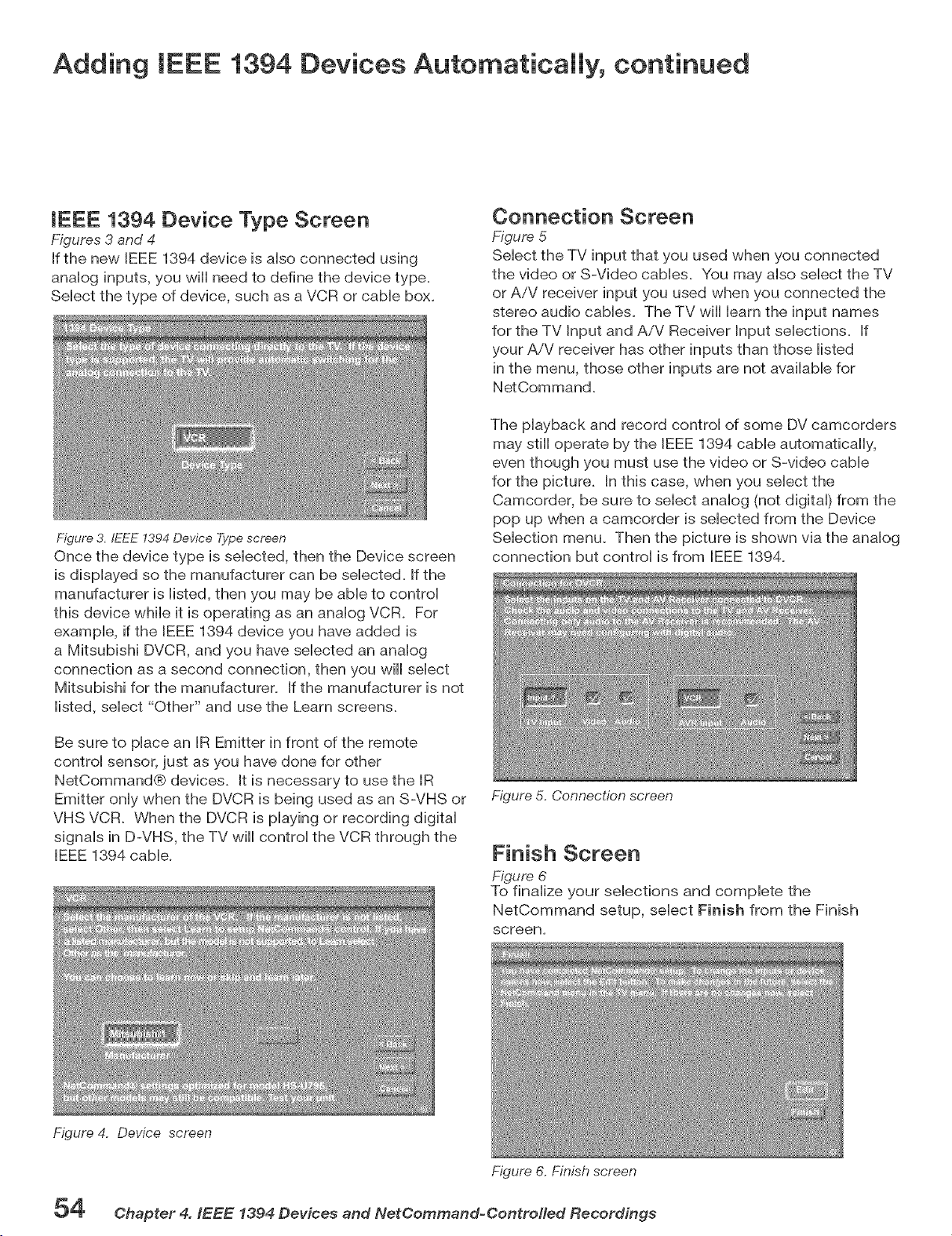
Adding IEEE 1394 Devices Automaticammy, continued
IEEE 1394 Device Type Screen
Figures 3 and 4
If the new IEEE 1394 device is aHso connected using
anaHog inputs, you will need to define the device type.
SeHect the type of device, such as a VCR or came box.
Figure 3. fEEE 1394 Device Type screen
Once the device type is seHected, then the Device screen
is dispHayed so the manufacturer can be seHected. If the
manufacturer is Histed, then you may be abHeto controH
this device whiHe it is operating as an anaHog VCR. For
exampHe, if the IEEE 1394 device you have added is
a Mitsubishi DVCR, and you have seHected an anaHog
connection as a second connection, then you will select
Mitsubishi for the manufacturer. If the manufacturer is not
listed, select "Other" and use the Learn screens.
Be sure to place an IR Emitter in front of the remote
control sensor, just as you have done for other
NetCommand® devices. It is necessary to use the IR
Emitter only when the DVCR is being used as an S-VHS or
VHS VCR. When the DVCR is playing or recording digital
signals in D-VHS, the TV will control the VCR through the
IEEE 1394 cable.
Figure 4. Device screen
Connection Screen
Figure 5
Select the TV input that you used when you connected
the video or S-Video cables. You may also select the TV
or AiV receiver input you used when you connected the
stereo audio cables. The TV will learn the input names
for the TV Input and A/V Receiver input selections. If
your A/V receiver has other inputs than those listed
in the menu, those other inputs are not available for
NetCommand.
The playback and record control of some DV camcorders
may still operate by the IEEE 1394 cable automatically,
even though you must use the video or S-video cable
for the picture. In this case, when you select the
Camcorder, be sure to select analog (not digital) from the
pop up when a camcorder is selected from the Device
Selection menu. Then the picture is shown via the analog
connection but control is from IEEE 1394.
Figure 5. CoPinection screen
Finish Screen
Figure 6
To finalize your selections and complete the
NetCommand setup, select Finish from the Finish
screen.
Figure 6. Finish screen
54 Chapter 4. IEEE 1394 Devices and NetOommand-Oontro//ed Recordings
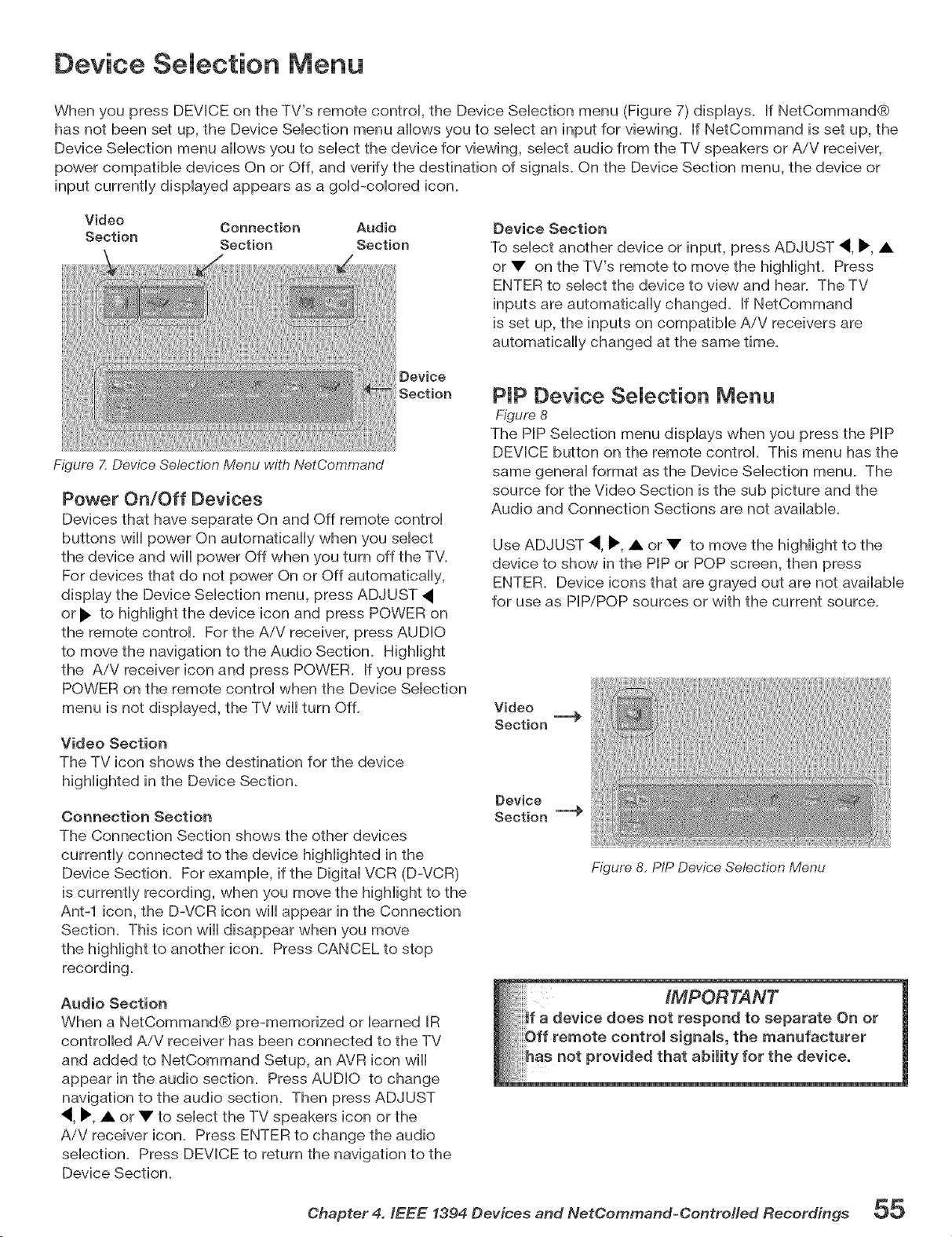
Device Selection Menu
When you press DEVICE on the TV's remote control, the Device Selection menu (Figure 7) displays. If NetCommand®
has not been set up, the Device Selection menu allows you to select an input for viewing. If NetCommand is set up, the
Device Selection menu allows you to select the device for viewing, select audio from the TV speakers or AiV receiver,
power compatible devices On or Off, and verify the destination of signals. On the Device Section menu, the device or
input currently displayed appears as a gold-colored icon.
Video
Connection Audio
Section
Section Section
Device Section
To select another device or input, press ADJUST 4, I_ •
or • on the TV's remote to move the highlight. Press
ENTER to select the device to view and hear. The TV
inputs are automatically changed. If NetCommand
is set up, the inputs on compatible AiV receivers are
automatically changed at the same time.
Device
Section
Figure 7. Device Selection Menu with NetCommand
Power On/Off Devices
Devices that have separate On and Off remote control
buttons will power On automatically when you select
the device and will power Off when you turn off the TV.
For devices that do not power On or Off automatically,
display the Device Selection menu, press ADJUST
or I_" to highlight the device icon and press POWER on
the remote control. For the AiV receiver, press AUDIO
to move the navigation to the Audio Section. Highlight
the AiV receiver icon and press POWER. If you press
POWER on the remote control when the Device Selection
menu is not displayed, the TV will turn Off.
Video Section
The TV icon shows the destination for the device
highlighted in the Device Section.
Connection Section
The Connection Section shows the other devices
currently connected to the device highlighted in the
Device Section. For example, if the Digital VCR (D-VCR)
is currently recording, when you move the highlight to the
Ant-1 icon, the D-VCR icon will appear in the Connection
Section. This icon will disappear when you move
the highlight to another icon. Press CANCEL to stop
recording.
PIP Device SeJection Menu
Figure 8
The PIP Selection menu displays when you press the PIP
DEVICE button on the remote control. This menu has the
same general format as the Device Selection menu. The
source for the Video Section is the sub picture and the
Audio and Connection Sections are not available.
Use ADJUST 4, I_ • or • to move the highlight to the
device to show in the PIP or POP screen, then press
ENTER. Device icons that are grayed out are not available
for use as PIP/POP sources or with the current source.
Video
Section --@
Device
Section I..@
Figure 8, PIP Device Selection Menu
Audio Section
When a NetCommand® pre-memorized or learned IR
controlled AiV receiver has been connected to the TV
and added to NetCommand Setup, an AVR icon will
appear in the audio section. Press AUDIO to change
navigation to the audio section. Then press ADJUST
4, _', • or • to select the TV speakers icon or the
AiV receiver icon. Press ENTER to change the audio
selection. Press DEVICE to return the navigation to the
Device Section.
Ohapter 4. IEEE 1394 Devices and NetOommand-OontreHed Recordings 55
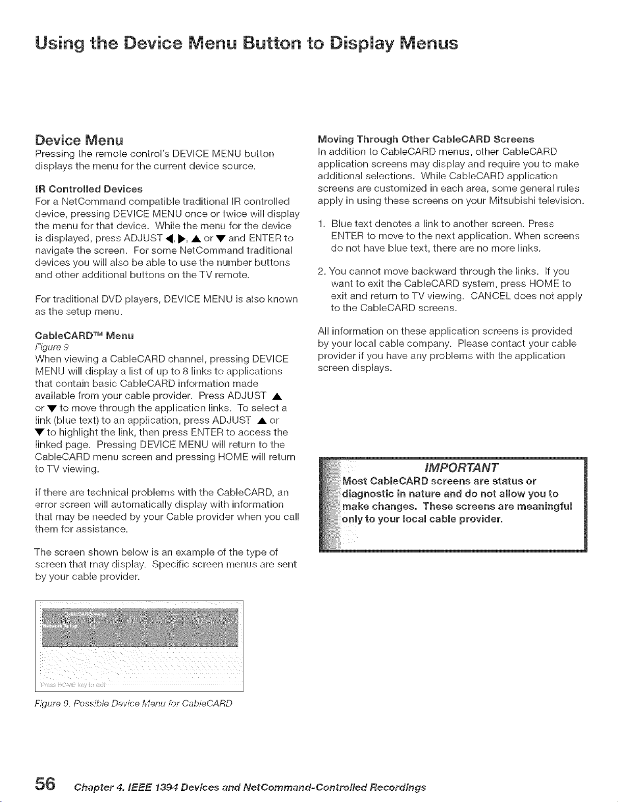
Using the Device Menu Button to Display Menus
Device Menu
Pressing the remote control's DEVICE MENU button
displays the menu for the current device source.
IR Controlled Devices
For a NetCommand compatible traditional IR controlled
device, pressing DEVICE MENU once or twice wiii display
the menu for that device. While the menu for the device
is displayed, press ADJUST ,, _., • or V and ENTER to
navigate the screen. For some NetCommand traditional
devices you wiii also be able to use the number buttons
and other additional buttons on the TV remote.
For traditional DVD players, DEVICE MENU is also known
as the setup menu.
CableCARD TM Menu
Figure 9
When viewing a CabieCARD channel, pressing DEVICE
MENU will display a list of up to 8 links to applications
that contain basic CableCARD information made
available from your cable provider. Press ADJUST •
or • to move through the application links. To select a
link (blue text) to an application, press ADJUST • or
• to highlight the link, then press ENTER to access the
linked page. Pressing DEVICE MENU will return to the
CableCARD menu screen and pressing HOME will return
to TV viewing.
if there are technical problems with the CableCARD, an
error screen will automatically display with information
that may be needed by your Cable provider when you caii
them for assistance.
The screen shown below is an example of the type of
screen that may display. Specific screen menus are sent
by your cable provider.
Moving Through Other CableOARD Screens
in addition to CableCARD menus, other CableCARD
application screens may display and require you to make
additional selections. While CableCARD application
screens are customized in each area, some general rubs
apply in using these screens on your Mitsubishi television.
1. Blue text denotes a link to another screen. Press
ENTER to move to the next application. When screens
do not have blue text, there are no more links.
2.
You cannot move backward through the links, if you
want to exit the CableCARD system, press HOME to
exit and return to TV viewing. CANCEL does not apply
to the CableCARD screens.
All information on these application screens is provided
by your iocai cable company. Please contact your cable
provider if you have any problems with the application
screen displays.
Figure 9. Possible Device Menu for CabteCARD
5_ @hapter 4. IEEE 1394 Devices and NetOommand=Oontrotled Recordings
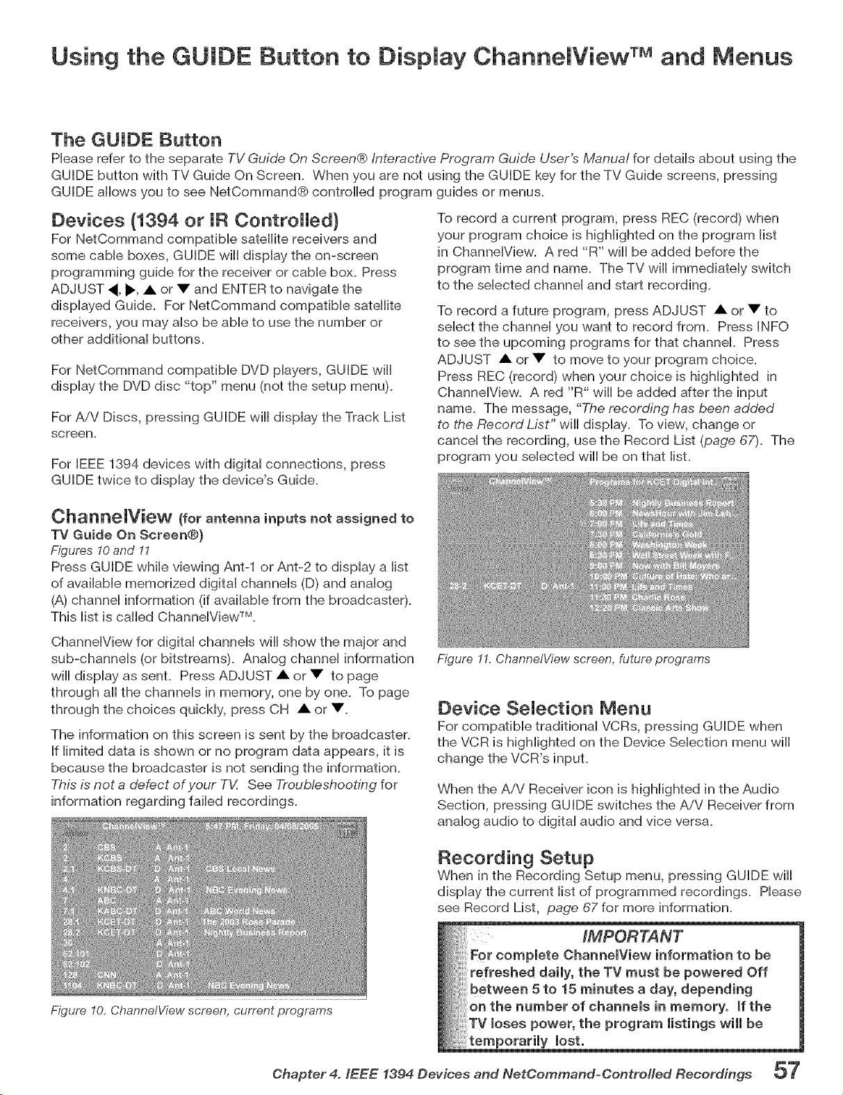
Using the GUIDE Button to Display ChannelView TMand Menus
The GUIDE Button
Phase refer to the separate TV Guide On Screen® Interactive Program Guide User's Manua/ for detaiis about using the
GUIDE button with TV Guide On Screen. When you are not using the GUIDE key for the TV Guide screens, pressing
GUIDE allows you to see NetCommand® controlled program guides or menus.
Devices (1394 or IR Controlled)
For NetCommand compafibb satellite receivers and
some cabb boxes, GUIDE will dispiay the on-screen
programming guide for the receiver or came box. Press
ADJUST 4, _, • or • and ENTER to navigate the
displayed Guide. For NetCommand compatible satellite
receivers, you may also be able to use the number or
other additional buttons.
For NetCommand compatible DVD players, GUIDE will
display the DVD disc "top" menu (not the setup menu).
For AiV Discs, pressing GUIDE will display the Track List
screen.
For IEEE 1394 devices with digital connections, press
GUIDE twice to display the device's Guide.
To record a current program, press REC (record) when
your program choice is highlighted on the program list
in ChannelView. A red "R" will be added before the
program time and name. The TV will immediately switch
to the selected channel and start recording.
To record a future program, press ADJUST • or • to
select the channel you want to record from. Press INFO
to see the upcoming programs for that channel. Press
ADJUST • or • to move to your program choice.
Press REC (record) when your choice is highlighted in
ChannelView. A red "R" will be added after the input
name. The message, "The recording has been added
to the Record List" will display. To view, change or
cancel the recording, use the Record List (page 67). The
program you selected will be on that list.
Oha[l[le_View (for antenna inputs not assigned to
TV Guide On Screen®)
Figures 10and 11
Press GUIDE while viewing Ant-1 or Ant-2 to display a list
of available memorized digital channels (D) and analog
(A) channel information (if available from the broadcaster).
This list is called ChannelView TM.
ChannelView for digital channels wiii show the major and
sub-channels (or bitstreams). Analog channel information
wiii display as sent. Press ADJUST • or • to page
through all the channels in memory, one by one. To page
through the choices quickly, press CH • or •.
The information on this screen is sent by the broadcaster.
If limited data is shown or no program data appears, it is
because the broadcaster is not sending the information.
This is not a defect of your TV. See Troub/eshooting for
information regarding failed recordings.
Figure 11. ChannetView screen, future programs
Device SeJection Menu
For compatible traditional VCRs, pressing GUIDE when
the VCR is highlighted on the Device Selection menu will
change the VCR's input.
When the AiV Receiver icon is highlighted in the Audio
Section, pressing GUIDE switches the AiV Receiver from
analog audio to digital audio and vice versa.
Recording Setup
When in the Recording Setup menu, pressing GUIDE will
display the current list of programmed recordings. Please
see Record List, page 67 for more information.
Figure 10, ChannelView screen, current programs
Chapter 4. IEEE 1394 Devices and NetCommand-Controfled Recordings 57
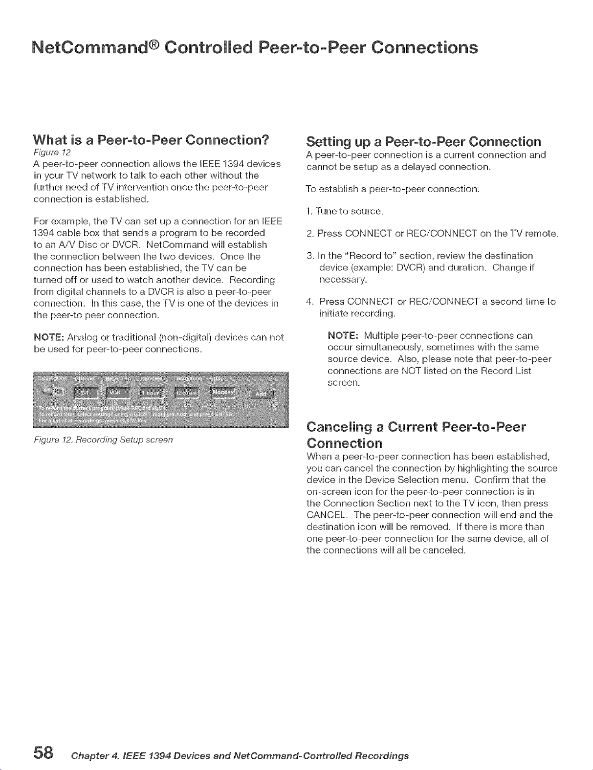
NetCommand ® Controlled Peer-to-Peer Connections
What is a Peer-to-Peer Connection?
Figure 12
A peer-to-peer connection allows the IEEE 1394 devices
in your TV network to taHkto each other without the
further need of TV intervention once the peer-to-peer
connection is established.
For exampHe, the TV can set up a connection for an JEEE
1394 came box that sends a program to be recorded
to an AiV Disc or DVCR. NetCommand will estaMish
the connection between the two devices. Once the
connection has been estabHished, the TV can be
turned off or used to watch another device. Recording
from digitaH channeHs to a DVCR is aHso a peer-to-peer
connection. In this case, the TV is one of the devices in
the peer-to peer connection.
NOTE: AnaHog or tradifionaH (non-digital) devices can not
be used for peer-to-peer connections.
Setting up a Peer4o-Peer Connection
A peer-to-peer connection is a current connection and
cannot be setup as a delayed connection.
To establish a peer-to-peer connection:
1. Tune to source.
2. Press CONNECT or RECiCONNECT on the TV remote.
3. In the "Record to" section, review the destination
device (example: DVCR) and duration. Change if
necessary.
4. Press CONNECT or RECiCONNECT a second time to
NOTE: Multiple peer-to-peer connections can
occur simultaneously, sometimes with the same
source device. Also, please note that peer-to-peer
connections are NOT listed on the Record List
screen.
Figure 12, Recording Setup screen
CanceJing a Current Peer-to-Peer
When a peer-to-peer connection has been established,
you can cancel the connection by highlighting the source
device in the Device Selection menu. Confirm that the
on-screen icon for the peer-to-peer connection is in
the Connection Section next to the TV icon, then press
CANCEL The peer-to-peer connection will end and the
destination icon will be removed. If there is more than
one peer-to-peer connection for the same device, all of
the connections will all be canceled.
58 Chapter 4. IEEE 1394 Devices and NetCommand-ControHed Recordings
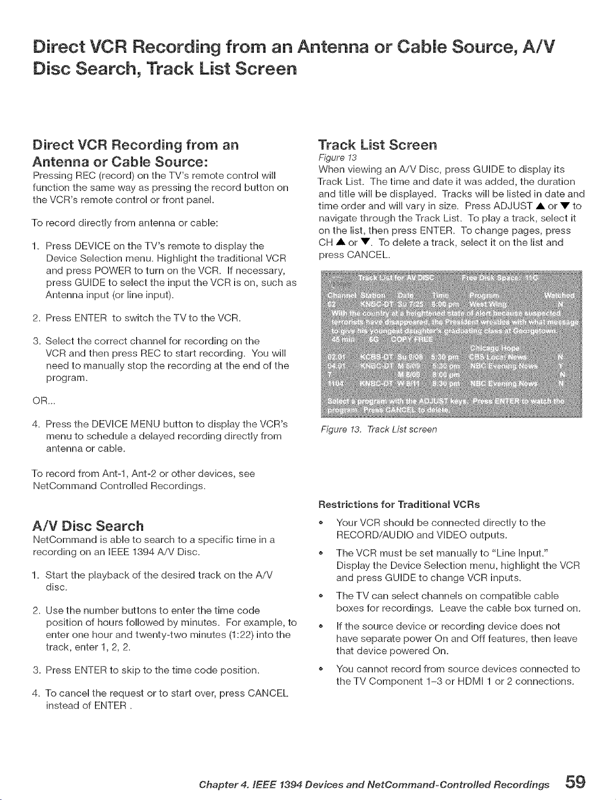
Direct VCR Recording from an Antenna or Cable Source, A!V
Disc Search, Track List Screen
Direct VCR Recording from an
Antenna or CabJe Source:
Pressing REC (record) on the TV's remote control wiii
function the same way as pressing the record button on
the VCR's remote control or front panel.
To record directly from antenna or cable:
1. Press DEVICE on the TV's remote to display the
Device Selection menu. Highlight the traditional VCR
and press POWER to turn on the VCR. if necessary,
press GUIDE to select the input the VCR is on, such as
Antenna input (or line input).
2. Press ENTER to switch the TV to the VCR.
3. Select the correct channel for recording on the
VCR and then press REC to start recording. You wiii
need to manually stop the recording at the end of the
program.
OR...
4. Press the DEVICE MENU button to display the VCR's
menu to schedule a delayed recording directly from
antenna or cable.
To record from Ant-l, Ant-2 or other devices, see
NetCommand Controlled Recordings.
A/V Disc Search
NetCommand is able to search to a specific time in a
recording on an IEEE 1394 AiV Disc.
1. Start the playback of the desired track on the AiV
disc.
2. Use the number buttons to enter the time code
position of hours followed by minutes. For example, to
enter one hour and twenty-two minutes (1:22) into the
track, enter 1, 2, 2.
3. Press ENTER to skip to the time code position.
4. To cancel the request or to start over, press CANCEL
instead of ENTER
Track List Screen
Figure 13
When viewing an AiV Disc, press GUIDE to dispiay its
Track List. The time and date it was added, the duration
and title wiii be displayed. Tracks wiii be listed in date and
time order and wiii vary in size. Press ADJUST A or V" to
navigate through the Track List. To play a track, select it
on the iist, then press ENTER. To change pages, press
CH • or V To delete a track, select it on the list and
press CANCEL.
Figure 13. Track List screen
Restrictions for Traditional VORs
Your VCR should be connected directly to the
RECORD/AUDIO and VIDEO outputs.
o The VCR must be set manually to "Line InpuL"
Display the Device Selection menu, highlight the VCR
and press GUIDE to change VCR inputs.
o The TV can select channels on compatible cable
boxes for recordings. Leave the cable box turned on.
o If the source device or recording device does not
have separate power On and Off features, then leave
that device powered On.
o You cannot record from source devices connected to
the TV Component 1-3 or HDMI 1 or 2 connections.
Chapter 4. IEEE 1394 Devices and NetCommand=Contrefled Recordings 59

Main Menu Choices ............................................................................ 62
Setup Menu .......................................................................................... 63
NetCommand® Menu ......................................................................... 65
Record Menu ....................................................................................... 6G
ChanneU Menu ...................................................................................... G8
Captions Menu .................................................................................... 70
V-Chip Lock Menu ............................................................................... 72
Audio/Video Menu .............................................................................. 75
A/V Settings Descriptions .................................................................. 76
Operation of PIP and POP .................................................................. 78
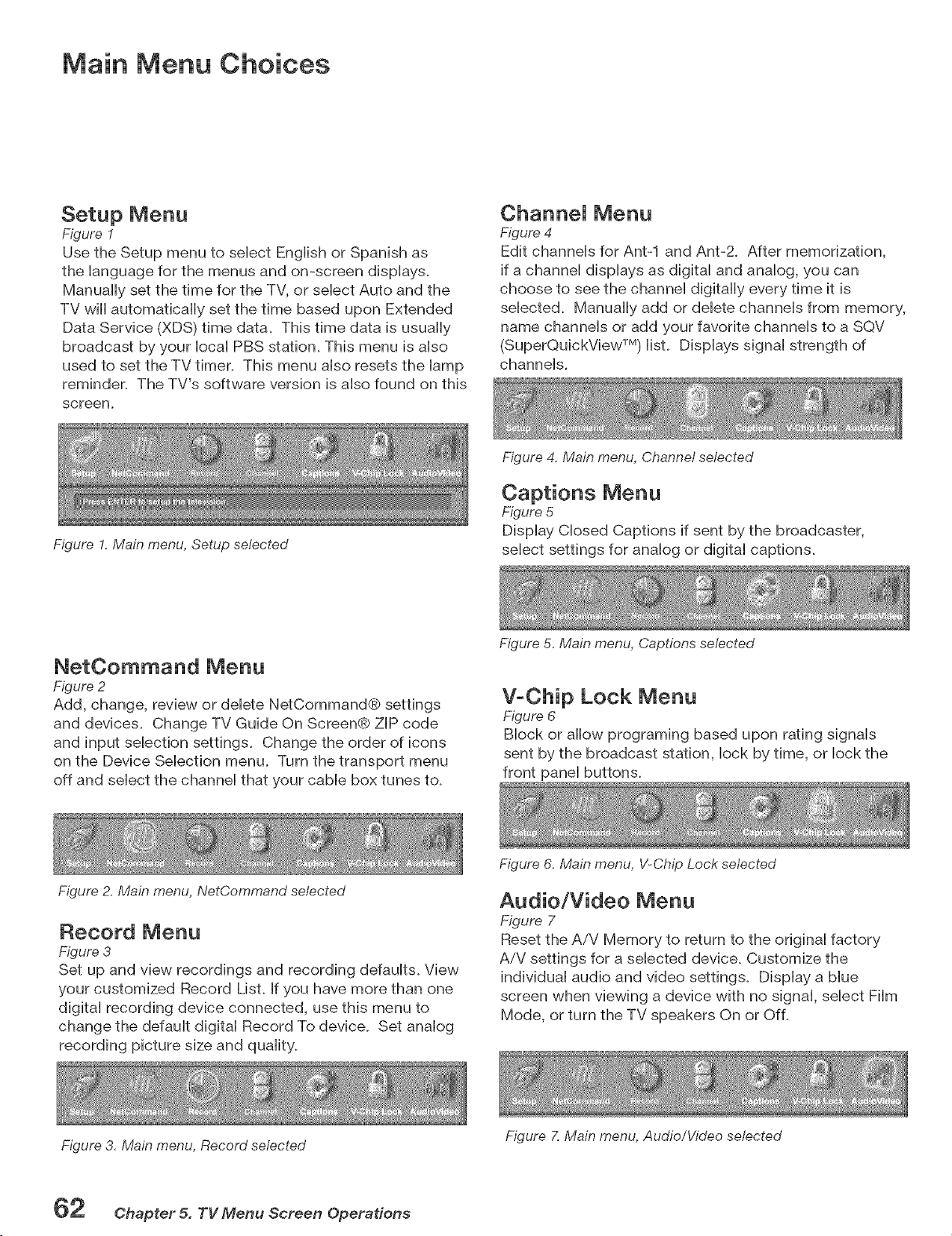
Main Menu Choices
Setup Menu
Figure I
Use the Setup menu to seHect EngHishor Spanish as
the Hanguage for the menus and on-screen dispHays.
Manually set the time for the TV, or seHect Auto and the
TV will automatically set the time based upon Extended
Data Service (XDS) time data. This time data is usually
broadcast by your HocaHPBS station. This menu is aHso
used to set the TV timer. This menu aHsoresets the Hamp
reminden The TV's software version is aHsofound on this
screen.
ChanneJ Menu
Figure 4
Edit channeHs for Ant-1 and Ant-2. After memorization,
if a channeH dispHays as digitaH and anaHog, you can
choose to see the channel digitally every time it is
selected. Manually add or delete channels from memory,
name channels or add your favorite channels to a SQV
(SuperQuickView TM) list. Displays signal strength of
channels.
Figure 1. Main menu, Setup selected
Figure 4. Main menu, Channel selected
Captions Menu
Figure 5
Display Closed Captions if sent by the broadcaster,
select settings for analog or digital captions.
NetOommand Menu
Figure 2
Add, change, review or delete NetCommand@ settings
and devices. Change TV Guide On Screen@ ZIP code
and input selection settings. Change the order of icons
on the Device Selection menu. Turn the transport menu
off and select the channel that your cable box tunes to.
Figure 2. Main menu, NetCommand selected
Figure 5, Main menu, Captions selected
V-Chip Lock Menu
Figure 6
Block or allow programing based upon rating signals
sent by the broadcast station, lock by time, or lock the
front panel buttons.
Record Menu
Figure 3
Set up and view recordings and recording defaults. View
your customized Record List. If you have more than one
digital recording device connected, use this menu to
change the default digital Record To device. Set analog
recording picture size and quality_
Figure 6, Main menu, V-Chip Lock selected
Audio/Video Menu
Figure 7
Reset the AiV Memory to return to the original factory
AiV settings for a selected device. Customize the
individual audio and video settings. Display a blue
screen when viewing a device with no signal, select Film
Mode, or turn the TV speakers On or Off.
Figure 3, Main menu, Record selected
Figure 7, Main menu, Audio/Video selected
Chapter 5. TV Menu Screen Operations
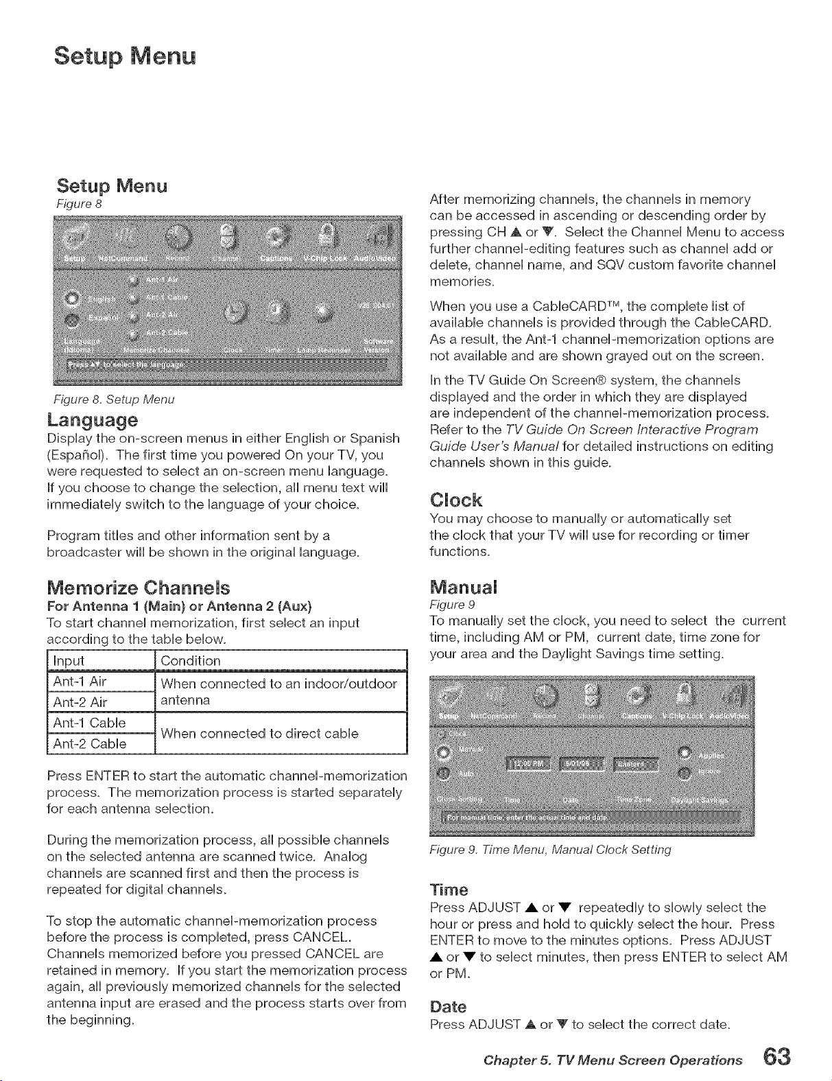
Setup Menu
Setup Menu
Figure 8
Figure 8. Setup Menu
Dispiay the on-screen menus in either Engibh or Spanish
(EspaBoi). The first time you powered On your TV, you
were requested to seiect an on-screen menu ianguage.
If you choose to change the sebcfion, aH menu text will
immediateiy switch to the ianguage of your chobe.
Program tities and other information sent by a
broadcaster wiii be shown in the originai language.
Memorize ChanneJs
Fer Antenna 1 (Main} er Antenna 2 (Aux}
To start channei memorization, first sebct an input
according to the tame bellow.
Input
Ant-1 Air
Ant-2 Air
Ant-1 Cable
Ant-2 Cable
Condition
When connected to an indoor/outdoor
antenna
When connected to direct cable
Press ENTER to start the automatic channel-memorization
process. The memorization process is started separately
for each antenna selection.
During the memorization process, all possible channels
on the selected antenna are scanned twice. Analog
channels are scanned first and then the process is
repeated for digital channels.
To stop the automatic channel-memorization process
before the process is completed, press CANCEL.
Channels memorized before you pressed CANCEL are
retained in memory. If you start the memorization process
again, all previously memorized channels for the selected
antenna input are erased and the process starts over from
the beginning.
After memorizing channels, the channels in memory
can be accessed in ascending or descending order by
pressing CH A or Y. Select the Channel Menu to access
further channel-editing features such as channel add or
delete, channel name, and SQV custom favorite channel
memories.
When you use a CableCARD TM, the complete list of
available channels is provided through the CableCARD.
As a result, the Ant-1 channel-memorization options are
not available and are shown grayed out on the screen.
In the TV Guide On Screen@ system, the channels
displayed and the order in which they are displayed
are independent of the channel-memorization process.
Refer to the TV Guide On Screen Interactive Program
Guide User's Manual for detailed instructions on editing
channels shown in this guide.
CJock
You may choose to manually or automatically set
the clock that your TV wiii use for recording or timer
functions.
Figure 9
To manually set the clock, you need to select the current
time, including AM or PM, current date, time zone for
your area and the Daylight Savings time setting.
Figure 9, Time Menu, Manual Clock Setting
Time
Press ADJUST A or • repeatedly to slowly select the
hour or press and hold to quickly select the hour. Press
ENTER to move to the minutes options. Press ADJUST
A or • to select minutes, then press ENTER to select AM
or PM.
Date
Press ADJUST a. or _' to select the correct date.
Chapter 5. TV Menu Screen Operatiens 63
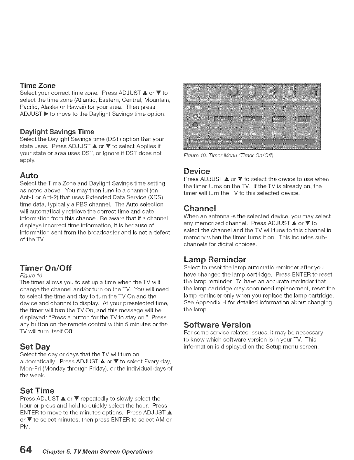
Time Zone
Sebct your correct time zone. Press ADJUST _ or T to
sebct the time zone (Atlantic, Eastern, Centrai, Mountain,
Pacific, Aiaska or Hawaii) for your area. Then press
ADJUST _ to move to the Dayiight Savings time option.
Select the Daylight Savings time (DST) option that your
state uses. Press ADJUST A or _ to select Applies if
your state or area uses DST, or Ignore if DST does not
apply.
Auto
Seiect the Time Zone and Dayiight Savings time setting,
as noted above. You may then tune to a channel (on
Ant-1 or Ant-2) that uses Extended Data Service (XDS)
time data, typically a PBS channel. The Auto selection
will automatically retrieve the correct time and date
information from this channel. Be aware that if a channel
displays incorrect time information, it is because of
information sent from the broadcaster and is not a defect
of the TV.
Timer On/Off
Figure 10
The timer allows you to set up a time when the TV will
change the channei and/or turn on the TM You will need
to sebct the time and day to turn the TV On and the
device and channei to dispiay. At your presebcted time,
the timer will turn the TV On, and this message will be
displayed: "Press a button for the TV to stay on." Press
any button on the remote control within 5 minutes or the
TV will turn itself Off.
Set Day
Select the day or days that the TV will turn on
automatically. Press ADJUST A or Y to select Every day,
Mon-Fri (Monday through Friday), or the individual days of
the week.
Set Time
Press ADJUST A or T repeatedly, to slowly select the
hour or press and hold to quickly select the hour. Press
ENTER to move to the minutes options. Press ADJUST A
or V to select minutes, then press ENTER to select AM or
PM.
Figure I0. Timer Menu (Timer On/Off)
Device
Press ADJUST A or _' to select the device to use when
the timer turns on the TV. If the TV is already on, the
timer wiii turn the TV to this selected device.
When an antenna _'sthe selected device, you may select
any memorized channel. Press ADJUST A or V to
select the channel and the TV will tune to this channel in
memory when the timer turns it on. This includes sub-
channels for digital choices.
Lamp Reminder
Select to reset the lamp automatic reminder after you
have changed the lamp cartridge. Press ENTER to reset
the lamp reminder. To have an accurate reminder that
the lamp cartridge may soon need replacement, reset the
lamp reminder only when you replace the lamp cartridge.
See Appendix H for detailed information about changing
the lamp.
Software Version
For some service related issues, it may be necessary
to know which software version is in your TV. This
information is displayed on the Setup menu screen.
64 @hapter 5. TV Menu Screen Operations
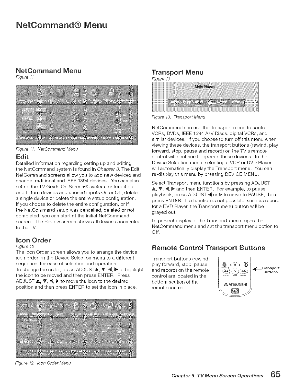
NetCommand® Menu
NetCommand Menu
Figure 11
Figure 11. NetComrnand Menu
Transport Menu
Figure !3
Detailed information regarding setting up and editing
the NetCommand system is found in Chapter& The Edit
NetCommand screens allow you to add new devices and
change traditional and IEEE 1894 devices. You can also
set up the TV Guide On Screen@ system, or turn it on
or of L Turn devices and unused inputs On or Off, delete
a single device or delete the entire setup configuration.
If you choose to delete the entire configuration, or if
the NetCommand setup was cancelled, deleted or not
completed, you can start at the hitial NetCommand
screen. The Review screen shows all devices connected
to the TV.
icon Order
Figure 12
The ben Order screen allows you to arrange the device
icon order on the Device Sebcfion menu to a different
sequence, for ease of sebction and operation.
To change the order, press ADJUSTS, Y, 4, _ to highlight
the icon to be moved and then press ENTER. Press
ADJUST A V, 4, _ to move the icon to the desired
position and then press ENTER to set the icon in place.
Figure 13, Transport Menu
NetCommand can use the Transport menu to control
VCRs, DVDs, IEEE 1894 AiV Discs, digital VCRs, and
similar devices. If you choose to turn off this menu when
viewing these devices, the transport buttons (rewind, play
forward, stop, pause and record) on the TV's remote
control wiii continue to operate these devices, in the
Device Selection menu, selecting a VCR or DVD Hayer
wiii automatically display the Transport menu. You can
re-display this menu by pressing DEVICE MENU.
Select Transport menu functions by pressing ADJUST
_,, V', 4, _ and then ENTER. For example, to pause
playback, press ADJUST _ or _ to move to PAUSE, then
press ENTER. If a function is not possible, such as record
for a DVD Hayer, the Transport menu button wiii be
grayed ouL
To prevent display of the Transport menu, open the
NetCommand menu and set the transport menu option to
Of L
Remote ControJ Transport Buttons
Transport buttons (rewind,
play forward, stop, pause
and record) on the remote
control are located in the
bottom section of the
remote control.
sToP _,,sE
®
_L,_Transport
Buttons
Figure 12. Icon Order Menu
Chapter 5. TV Menu Screen Operations 65
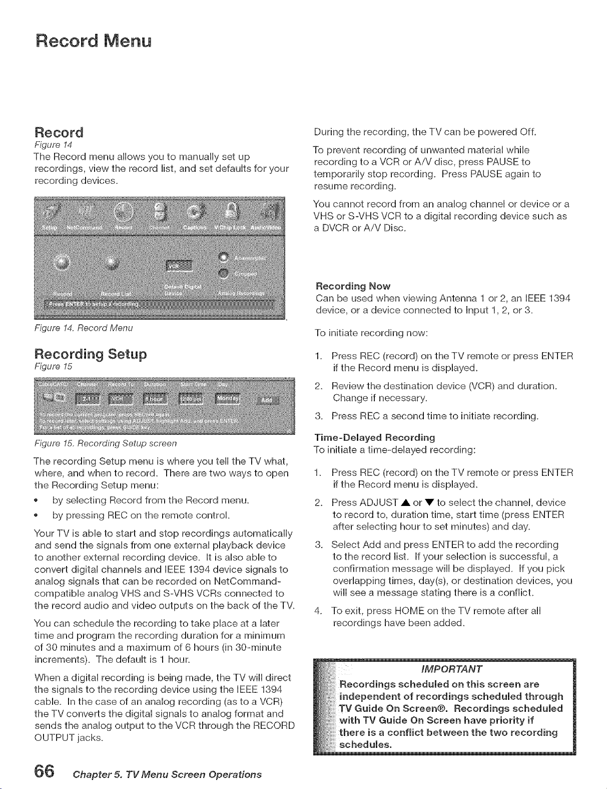
Record Menu
Record
Figure 14
The Record menu allows you to manually set up
recordings, view the record iist, and set defauits for your
recording devbes.
Figure 14. Record Menu
During the recording, the TV can be powered Of L
To prevent recording of unwanted materiai whib
recording to a VCR or AiV disc, press PAUSE to
temporariiy stop recording. Press PAUSE again to
resume recording.
You cannot record from an anaiog channei or device or a
VHS or S-VHS VCR to a digitai recording device such as
a DVCR or AiV Disc.
Recording Setup
Figure 15
Figure 15, Recording Setup screen
Recording Now
Can be used when viewing Antenna 1 or 2, an IEEE 1394
device, or a device connected to Bnput 1, 2, or 3.
To initiate recording now:
2.
3.
Press REC (record) on the TV remote or press ENTER
if the Record menu is dispiayed.
Review the destination device (VCR) and duration.
Change if necessary.
Press REC a second time to initiate recording.
Time=Delayed Recording
To initiate a time-delayed recording:
The recording Setup menu is where you teil the TV what,
where, and when to record. There are two ways to open 1.
the Recording Setup menu:
by selecting Record from the Record menu. 2.
by pressing REC on the remote control.
Your TV is able to start and stop recordings automatically
and send the signals from one external playback device 3.
to another external recording device. It is also able to
convert digital channels and IEEE 1394 device signals to
analog signals that can be recorded on NetCommand-
compatible analog VHS and S-VHS VCRs connected to
the record audio and video outputs on the back of the TV.
4.
You can schedule the recording to take place at a later
time and program the recording duration for a minimum
of 30 minutes and a maximum of 6 hours (in 30-minute
increments). The default is 1 hour.
When a digital recording is being made, the TV wiii direct
the signals to the recording device using the IEEE 1394
cable. In the case of an analog recording (as to a VCR)
the TV converts the digital signals to analog format and
sends the analog output to the VCR through the RECORD
OUTPUT jacks.
Press REC (record) on the TV remote or press ENTER
if the Record menu is displayed.
Press ADJUST A or • to select the channel, device
to record to, duration time, start time (press ENTER
after selecting hour to set minutes) and day.
Select Add and press ENTER to add the recording
to the record list. If your selection is successful, a
confirmation message wiii be displayed. If you pick
overlapping times, day(s), or destination devices, you
will see a message stating there is a conflicL
To exit, press HOME on the TV remote after all
recordings have been added.
iMPORTANT
Recordings scheduled on this screen are
independent of recordings scheduled through
/ Guide On Screen@. Recordings scheduled
with TV Guide On Screen have priority if
a conflict between the two recording
66 Chapter 5. TV Menu Screen Operations
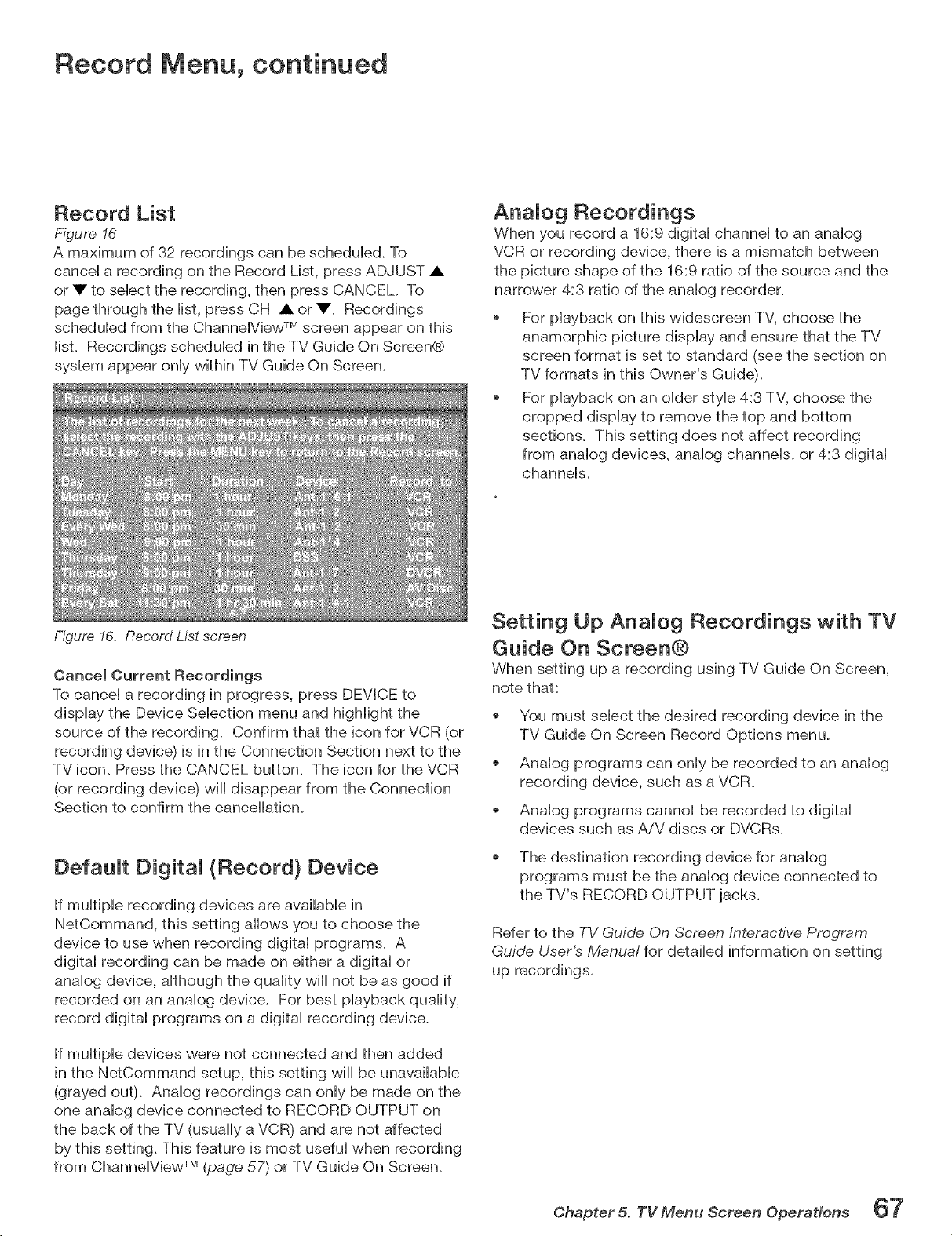
Record Menu, continued
Record List
Figure 16
A maximum of 32 recordings can be scheduied. To
cancel a recording on the Record List, press ADJUST •
or • to select the recording, then press CANCEL To
page through the list, press CH • or •. Recordings
scheduled from the Channe[Vbw TM screen appear on this
[bt. Recordings scheduled in the TV Guide On Screen®
system appear only within TV Guide On Screen.
Figure 16. Record List screen
Cancel Current Recordings
To cancel a recording in progress, press DEVICE to
display the Device Selection menu and highlight the
source of the recording. Confirm that the icon for VCR (or
recording device) is in the Connection Section next to the
TV icon. Press the CANCEL button. The icon for the VCR
(or recording device) will disappear from the Connection
Section to confirm the cancellation.
Default Digital (Record) Device
If multiple recording devices are available in
NetCommand, this setting allows you to choose the
device to use when recording digital programs. A
digital recording can be made on either a digital or
analog device, although the quality will not be as good if
recorded on an analog device. For best playback quality,
record digital programs on a digital recording device.
If multiple devices were not connected and then added
in the NetCommand setup, this setting wiii be unavailable
(grayed out). Analog recordings can only be made on the
one analog device connected to RECORD OUTPUT on
the back of the TV (usually a VCR) and are not affected
by this setting. This feature is most useful when recording
from ChanneiView TM (page 57) or TV Guide On Screen.
Analog Recordings
When you record a 16:9 digital channel to an analog
VCR or recording device, there is a mismatch between
the picture shape of the 16:9 ratio of the source and the
narrower 4:3 ratio of the analog recorder_
For playback on this widescreen TV, choose the
anamorphic picture display and ensure that the TV
screen format is set to standard (see the section on
TV formats in this Owner's Guide).
For playback on an older sue 4:8 TV, choose the
cropped display to remove the top and bottom
sections. This setting does not affect recording
from analog devices, analog channels, or 4:3 digital
channels.
Setting Up Analog Recordings with TV
Guide On Screen@
When setting up a recording using TV Guide On Screen,
note that:
You must select the desired recording device in the
TV Guide On Screen Record Options menu.
o Analog programs can only be recorded to an analog
recording device, such as a VCR.
Analog programs cannot be recorded to digital
devices such as AiV discs or DVCRs.
The destination recording device for analog
programs must be the analog device connected to
the TV's RECORD OUTPUT jacks.
Refer to the TV Guide On Screen Interactive Program
Guide User's Manua! for detailed information on setting
up recordings_
Chapter 5. TV Menu Screen Operations 67
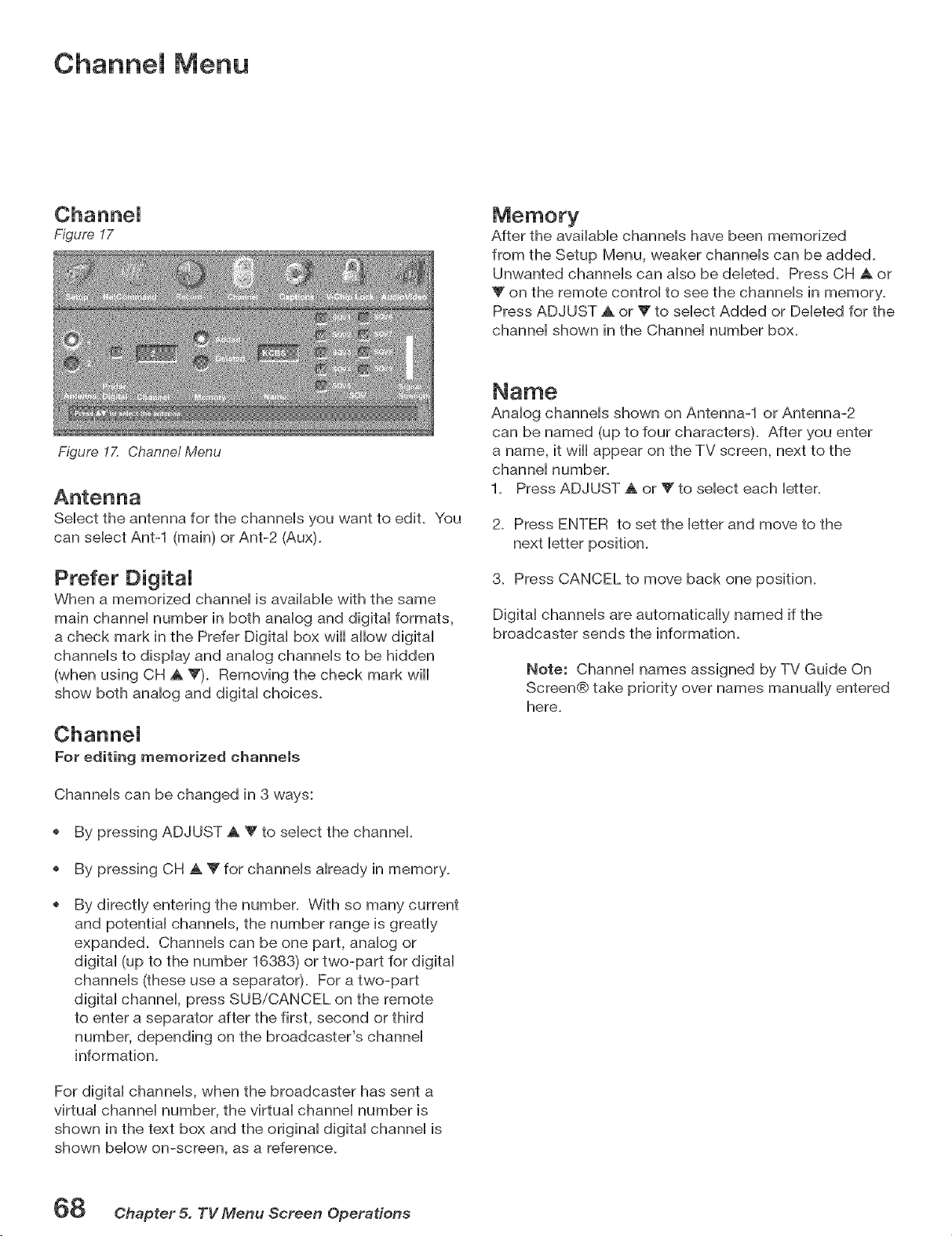
Channel Menu
Figure 17
Figure 17. Channel Menu
After the avaiiaMe channeis have been memorized
from the Setup Menu, weaker channeis can be added.
Unwanted channeis can abo be debted. Press CH _ or
on the remote controi to see the channeb in memory.
Press ADJUST A or V to sebct Added or Debted for the
channei shown in the Channei number box.
Select the antenna for the channels you want to edit. You
can select Ant-1 (main) or Ant-2 (Aux).
Prefer DigitaJ
When a memorized channei is avaiiabb with the same
main channei number in both anaiog and digitai formats,
a check mark in the Prefer Digitai box will allow digitai
channeis to dispiay and anaiog channeis to be hidden
(when using CH A Y). Removing the check mark will
show both analog and digital choices.
Analog channels shown on Antenna-1 or Antenna-2
can be named (up to four characters). After you enter
a name, it will appear on the TV screen, next to the
channel number.
1. Press ADJUST A or Y to select each letter.
2. Press ENTER to set the letter and move to the
next letter position.
3. Press CANCEL to move back one position.
Digital channels are automatically named if the
broadcaster sends the information.
Note: Channel names assigned by TV Guide On
Screen@ take priority over names manually entered
here.
For editing memorized channels
Channels can be changed in 3 ways:
By pressing ADJUST A Y to select the channel.
By pressing CH A _" for channels already in memory.
By directly entering the number. With so many current
and potential channels, the number range is greatly
expanded. Channels can be one part, analog or
digital (up to the number 16383) or two-part for digital
channels (these use a separator). For a two-part
digital channel, press SUB/CANCEL on the remote
to enter a separator after the first, second or third
number, depending on the broadcaster's channel
information.
For digital channels, when the broadcaster has sent a
virtual channel number, the virtual channel number is
shown in the text box and the original digital channel is
shown below on-screen, as a reference.
_8 @hapfer 5. TV Menu Screen Operations
SQV (SuperQuickView TM)
SQV (SuperQuickView TM)
Using The Menu Screen
Figure 17
SQV (SuperQuickView TM) allows you to put together Hists
of your favorite channels from Antenna 1 and Antenna
2. You can store channels in any of the 9 different SQV
memory banks. You can aHsostore the same channeH in
muHtipHememory banks. Once you have added a channel
to an SQV memory, "SQV" and the memory bank
number will appear under the tuned channel number on
the TV screen.
Adding SQV Channels
1. Select the channel using the "Channel" option box or
press CH _k _'.
2. Highlight the bank (SQV1-SQV9).
3. Press ENTER to check mark the selected SQV memory
bank.
4. Repeat for additional channels or banks.
Removing SQV Channels
1. Highlight the box for the SQV bank number.
2. Press ENTER to remove the check mark.
SQV (SuperQuickView TM)
Using The Remote Control
Viewing and changing SQV banks using the remote
control:
1. Press the SQV button.
2. To change memory banks, press a number button
within 5 seconds of pressing the SQV button.
3. Press the SQV button repeatedly to cycle through the
channels available in that bank.
Adding SQV channels using the remote control:
1. Press CH A _' or number buttons to select the
channel you want to add to the current SQV memory
bank.
2 Press ENTER.
3. Press and hold the SQV button for about 2 seconds.
When "SQV" and the memory bank number
appear under the channel number, the channel has
successfully been added.
Removing SQV channels using the remote control:
1. Press the SQV button and then the memory bank
number.
2. Press the SQV button repeatedly until you see the
desired channel.
.
While the channel number and SQV indicator (with
correct bank number) are still displayed on the screen,
press the CANCEL button. If the CANCEL button
is not pressed before the SQV indicator disappears
automatically, the channel will not be removed.
4. When the SQV indicator disappears, the channel
has successfully been removed only from that bank.
"Other" banks remain unchanged.
SignaJ Strength
Displays the approximate signal strength of the currently
tuned digital channel. Use to adjust the antenna direction
to optimize signal strength. The higher the bar, the
stronger the signal. Does not apply to analog channels.
You can change the tuned channel while in this menu
so that you can see the effects of antenna adjustments.
Highlight the channel box, press CH ,tk _" or ADJUST A T
to display the desired channel number, and press ENTER.
Chapter 5. TV Menu Screen Operations 69
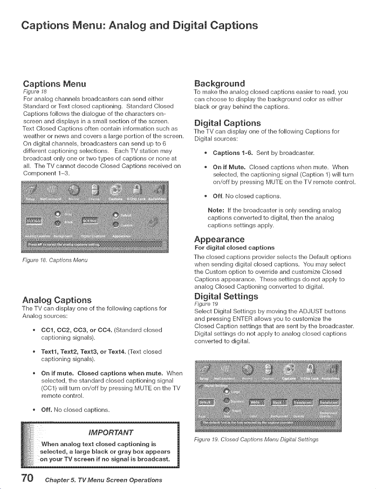
Captions Menu: Analog and Digital Captions
Captions Menu
Figure I8
For anaHog channeHs broadcasters can send either
Standard or Text dosed captioning. Standard CHosed
Captions follows the diaHogue of the characters on-
screen and dispHays in a small section of the screen.
Text CHosed Captions often contain information such as
weather or news and covers a Hargeportion of the screen.
On digitaH channeHs, broadcasters can send up to 6
different captioning seHecfions. Each TV station may
broadcast onHyone or two types of captions or none at
all. The TV cannot decode CHosed Captions received on
To make the anaHog dosed captions easier to read, you
can choose to display the background color as either
black or gray behind the captions.
Digital Captions
The TV can display one of the following Captions for
Digital sources:
Captions 1_6. Sent by broadcaster.
On if Mute. Closed captions when mute. When
selected, the captioning signal (Caption 1) will turn
on/off by pressing MUTE on the TV remote control.
Off. No closed captions.
Note: If the broadcaster is only sending analog
captions converted to digital, then the analog
captions settings apply.
Figure 18, Captions Menu
Analog Captions
The TV can display one of the following captions for
Analog sources:
001, 0C2, CC3, or 004. (Standard closed
captioning signals).
Text1, Text2, Text3, or Text4. (Text closed
captioning signals).
On if mute. Closed captions when mute. When
selected, the standard closed captioning signal
(CC1) will turn on/off by pressing MUTE on the TV
remote control.
Off. No closed captions.
For digital closed captions
The closed captions provider selects the Default options
when sending digital closed captions. You may select
the Custom option to override and customize Closed
Captions appearance. These settings do not apply to
analog Closed Captioning converted to digital
Digital Settings
Figure 19
Select Digital Settings by moving the ADJUST buttons
and pressing ENTER allows you to customize the
Closed Caption settings that are sent by the broadcaster.
Digital settings do not apply to analog closed captions
converted to digital.
Figure 19, Closed Captions Menu Digital Settings
TV screen if gnal is broadcast,
70 Chapter 5. TV Menu Screen Operations
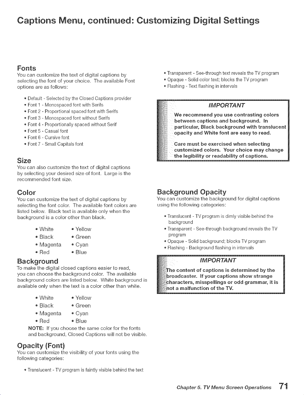
Captions Menu, continued: Customizing Digital Settings
You can customize the text of digitaH captions by
seHecfing the font of your choice. The avaiHabHeFont
options are as follows:
Defauk - Selected by the Closed Captions provider
Font 1 - Monospaced font with Serifs
Font 2 - ProportionaI spaced font with Serifs
Font 3 - Monospaced font without Serifs
Font 4 -ProportionaIIy spaced without Serif
Font 5 - Casuat font
, Font 6 - Cursive font
Font 7 - Small Capitats font
Size
You can aHsocustomize the text of digitaH captions
by seHecfing your desired size of font. Large is the
recommended font size.
CoJor
You can customize the text of digitaH captions by
seHecting the font coHor. The avaiHaMe font coHors are
Histed below. Black text is available only when the
background is a color other than black.
o White o Yellow
o Black o Green
o Magenta o Cyan
o Red o Blue
To make the digital closed captions easier to read,
you can choose the background color. The available
background colors are listed below. White background is
available only when the text is a color other than white.
o White o Yellow
o Black o Green
o Magenta o Cyan
o Red o Blue
NOTE: If you choose the same color for the fonts
and background, Closed Captions will not be visible.
Opacity (Font)
You can customize the visibility of your fonts using the
following categories:
, Translucent - TV program is faintty visible behind the text
, Transparent - See-through text reveals the TV program
Opaque -Soiid color text; blocks the TV program
, Flashing - Text flashing in intervals
IMPORTANT
We recommend you use contrasting colors
between captions and background, in
particular, Black background with translucent
opacity and White font are easy to read.
Care must be exercised when selecting
customized colors. Your choice may change
the legibility or readability of captions,
Background Opacity
You can customize the background for digital captions
using the following categories:
Translucent - TV program is dimly visible behind the
background
Transparent - See-through background reveals the TV
program
Opaque - SoIid background; bIocks TV program
Hashing - Background flashing in intervals
__s determined by the
__aptions show strange
oddgrammar,it is
Chapter 5. TV Menu Screen Operations
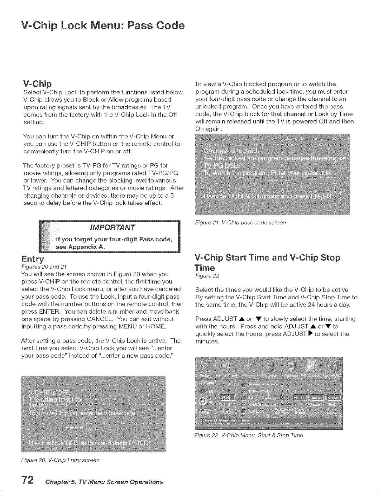
V-Chip Lock Menu: Pass Code
SeHectV-Chip Lock to perform the functions Histed bellow.
V-Chip allows you to BHock or AHow programs based
upon rating signaHs sent by the broadcaster. The TV
comes from the factory with the V-Chip Lock in the Off
setting.
You can turn the V-Chip on within the V-Chip Menu or
you can use the V-CHIP button on the remote controH to
conveniently turn the V-CHIP on or off.
The factory preset is TV-PG for TV ratings or PG for
movie ratings, allowing onHyprograms rated TV-PG/PG
or Hower. You can change the Mocking HeveHto various
TV ratings and Hettered categories or movie ratings. After
changing channeHs or devices, there may be up to a 5
second deHaybefore the V-Chip Hocktakes effect.
To view a V-Chip Mocked program or to watch the
program during a scheduHed Hocktime, you must enter
your four-digit pass code or change the channel to an
unlocked program. Once you have entered the pass
code, the V-Chip block for that channel or Lock by Time
will remain released until the TV is powered Off and then
On again.
IMPORTANT
u forget your four=digit Pass code,
Figures 20 and 21
You will see the screen shown in Figure 20 when you
press V-CHIP on the remote control, the first time you
select the V-Chip Lock menu, or after you have canceled
your pass code. To use the Lock, input a four-digit pass
code with the number buttons on the remote control, then
press ENTER. You can delete a number and move back
one space by pressing CANCEL. You can exit without
inputting a pass code by pressing MENU or HOME.
After setting a pass code, the V-Chip Lock is active. The
next time you select V-Chip Lock you will see "...enter
your pass code" instead of "...enter a new pass code."
Figure 2I, V-Chip pass code screen
V-Chip Start Time and V-Chip Stop
Figure 22
Select the times you would like the V-Chip to be active.
By setting the V-Chip Start Time and V-Chip Stop Time to
the same time, the V-Chip will be active 24 hours a day.
Press ADJUST • or • to slowly select the time, starting
with the hours. Press and hold ADJUST • or • to
quickly select the hours, press ADJUST • to select the
minutes.
Figure 20, V-Chip Entry screen
Chapter 5. TV Menu Screen Operations
Figure 22, V-Chip Menu, Start & Stop Time
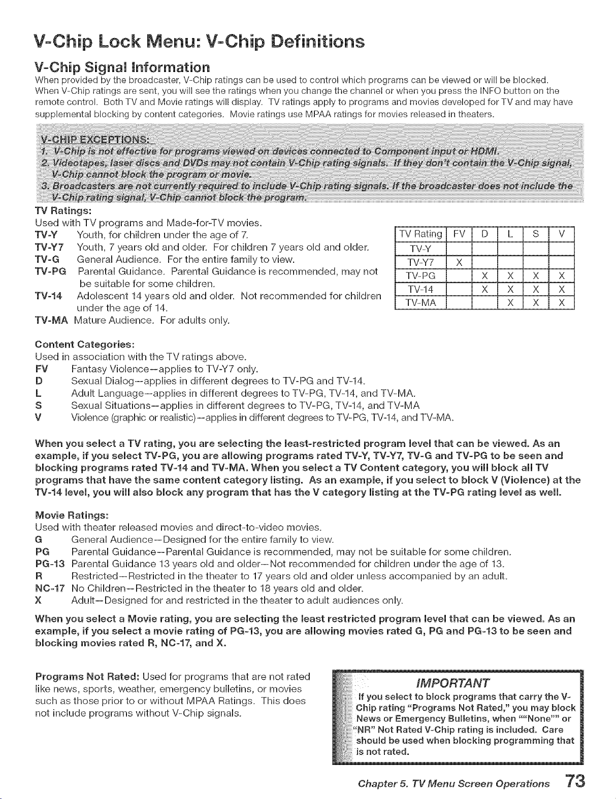
V+Chip Lock Menu: V+Chip Definitions
V-Chip Signal Information
When provided by the broadcaster, V-Chip ratings can be used to control which programs can be viewed or will be blocked.
When V-Chip ratings are sent, you will see the ratings when you change the channei or when you press the HNFObutton on the
remote control. Both TV and Movie ratings will display. TV ratings apply to programs and movies developed for TV and may have
supplementa! blocking by content categories. Movie ratings use MPAA ratings for movies released in theaters.
TV Ratings:
Used with TV programs and Made-for-TV movies.
TV-Y Youth, for cNdren under the age of 7+
TV-Y7 Youth, 7 years oHdand oHder. For cMHdren 7 years oHdand oHder.
TV-G GeneraHAudience. For the entire famiHy to view.
TV-PG ParentaHGuidance. ParentaH Guidance is recommended, may not
be suitabHe for some chiHdren+
TV-14 AdoHescent 14 years oHdand oHder+ Not recommended for chiHdren
under the age of 14+
TV-MA Mature Audience. For aduHts onHy+
TV Rating FV D L S V
TV-Y
TV-Y7 X
TV-PG X X X X
TV-14 X X X X
TV-MA X X X
Content Categories:
Used in association with the TV ratings above+
FV Fantasy VioHence--appHies to TV-V7 onHy+
D SexuaHDiaHog--appHies in different degrees to TV-PG and TV-14+
L AduHt Language--appHies in different degrees to TV-PG, TV-14, and TV-MA+
S SexuaH Situations--appHies in different degrees to TV-PG, TV-14, and TV-MA
V VioHence(graphic or reaHistic)--appHiesin different degrees to TV-PG, TV-14, and TV-MA+
When you semect a TV rating, you are semecting the recast-restricted program mevemthat can be viewed. As an
exampme, if you semect TV-PG, you are ammowingprograms rated TV-Y, TV-Y7, TV-G and TV-PG to be seen and
blocking programs rated TV-14 and TV-MA. When you select a TV Content category, you will block all TV
programs that have the same content category listing. As an example, if you select to block V (Violence} at the
TV-14 level, you will also block any program that has the V category listing at the TV-PG rating level as well.
Movie Ratings:
Used with theater reHeased movies and direct-to-video movies+
G GeneraH Audience-- Designed for the entire famiHyto view.
PG ParentaH Guidance--ParentaH Guidance is recommended, may not be suitabHe for some chiHdren+
PG-13 ParentaH Guidance 13 years oHdand oHder--Not recommended for chiHdren under the age of 13+
R Restricted--Restricted in the theater to 17 years oHdand oHder unHess accompanied by an aduHt+
N0-17 No ChiHdren--Restricted in the theater to 18 years oHdand oHder+
X AduHt-- Designed for and restricted in the theater to aduHtaudiences onHy+
When you semect a Movie rating, you are semecting the recast restricted program mevemthat can be viewed. As an
example, if you select a movie rating of PG-13, you are allowing movies rated G, PG and PG-13 to be seen and
blocking movies rated R, N0-17, and X.
Programs Not Rated: Used for programs that are not rated
Hikenews, sports, weather, emergency buHHetins,or movies
such as those prior to or without MPAA Ratings+ This does
not incHude programs without V-Chip signaHs+
Chapter 5. TV Menu Screen Operations 7 3
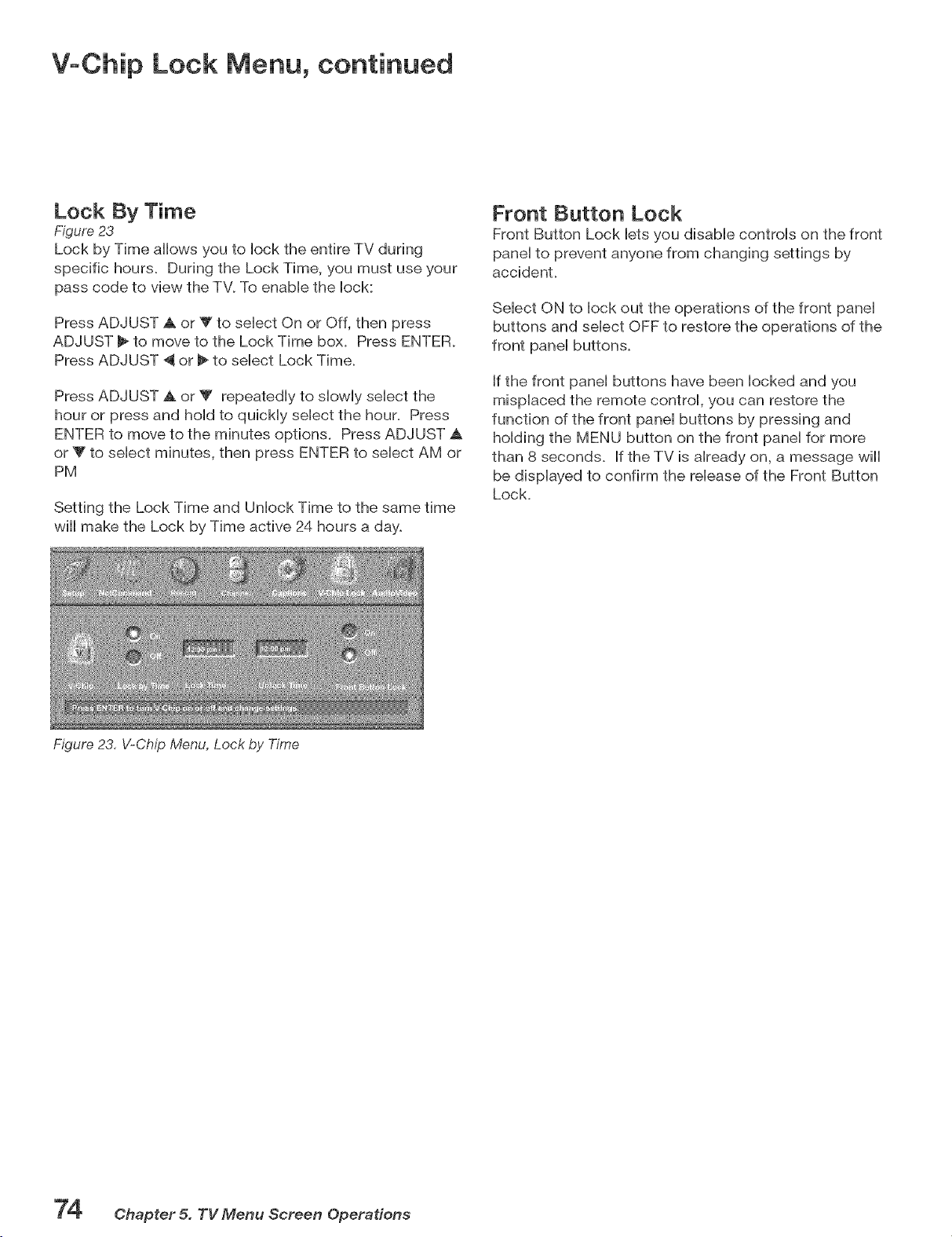
V-Chip Lock Menu, continued
Lock By Time
Figure 23
Lock by Time allows you to Hockthe entire TV during
specific hours+ During the Lock Time, you must use your
pass code to view the TV. To enabb the Hock:
Press ADJUST _k or Y to sebct On or Off, then press
ADJUST _- to move to the Lock Time box. Press ENTER+
Press ADJUST _J or _ to sebct Lock Time+
Press ADJUST A. or T repeatediy to showily sebct the
hour or press and hoid to quicHy sebct the hour. Press
ENTER to move to the minutes options. Press ADJUST _k
or _Fto sebct minutes, then press ENTER to sebct AM or
PM
Setting the Lock Time and Unbck Time to the same time
will make the Lock by Time active 24 hours a day.
Figure 23, V-Chip Menu, Lock by Time
Front Button Lock
Front Button Lock bts you disable controls on the front
panel to prevent anyone from changing settings by
accident+
Select ON to lock out the operations of the front panel
buttons and select OFF to restore the operations of the
front panel buttons+
If the front panel buttons have been locked and you
misplaced the remote control, you can restore the
function of the front panel buttons by pressing and
holding the MENU button on the front panel for more
than 8 seconds+ If the TV is already on, a message wiii
be displayed to confirm the release of the Front Button
Lock+
74 Chapter 5. TV Menu Screen Operations
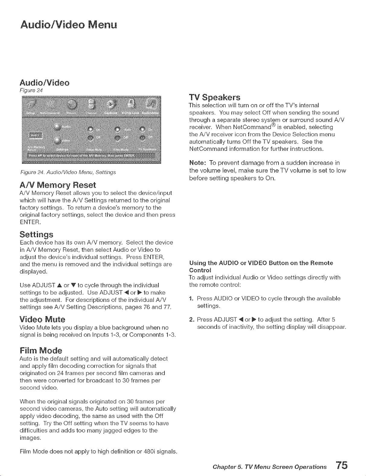
Audio!Video Menu
Figure 24
TV Speakers
This sebcfion will turn on or off the TV's intemai
speakers. You may sebct Off when sending the sound
Figure 24. Audio/Video Menu, Settings
A/V Memory Reset
AiV Memory Reset allows you to sebct the devbe/input
which will have the A/V Settings returned to the originai
factory settings. To return a device's memory to the
originai factory settings, sebct the device and then press
ENTER.
the AiV receiver icon from the Device Sebcfion menu
automatically turns Off the TV speakers. See the
NetCommand information for further instructions.
Note: To prevent damage from a sudden increase in
the volume level, make sure the TV volume is set to low
before setting speakers to On.
Each device has its own AiV memory, Select the device
in AiV Memory Reset, then select Audio or Video to
adjust the device's individual settings, Press ENTER,
and the menu is removed and the individual settings are
displayed,
Use ADJUST A or _" to cycle through the individual
settings to be adjusted, Use ADJUST 4 or _ to make
the adjustment, For descriptions of the individual A/V
settings see AiV Setting Descriptions, pages 76 and 7X
Video Mute
Video Mute lets you display a blue background when no
signal is being received on Inputs 1-3, or Components 1-3,
FiJm Mode
Auto is the defauit setting and will automatbaHy detect
and appiy film decoding correction for signals that
originated on 24 frames per second film cameras and
then were converted for broadcast to 30 frames per
second video.
When the original signals originated on 30 frames per
second video cameras, the Auto setting wiii automatically
apply video decoding, the same as used with the Off
setting, Try the Off setting when the TV seems to have
difficulties and adds too many jagged edges to the
images,
Film Mode does not apply to high definition or 480i signals,
Using the AUDIO oF WDEO Button on the Remote
Control
To adjust individual Audio or Video settings directly with
the remote controk
1. Press AUDIO or VIDEO to cycle through the available
settings,
2. Press ADJUST 4 or _ to adjust the setting. After 5
seconds of inactivity, the setting display will disappear.
Chapter 5. TV Menu Screen Operations 7 5
A!V Setting Descriptions: Audio
NOTE: The effects of the Audio Settings of Bass, Trebb, Baiance and Surround affect the sound heard through the ]
TV speakers oniy.
/
AnaJog and DigitaJ Audio Setting
A siider will dispiay on screen for most settings. When
the siider is dispiayed it has a numeric vaiue, where 63 is
the maximum, 31 is the mid-point and 0 is the minimum.
0 Bass
Enhances or reduces How-pitch sound.
0 Treble
Enhances or reduces high-pitch sound.
0 Balance
Adjusts the ievei of sound between the Heftand right
speakers.
0 Surround
Creates simuiated stereo and surround effects
through the TV speakers. Your choices are:
Off: No surround effects.
Simuiated Stereo: Your TV will create a simubted
stereo effect when watching a non-stereo program.
Surround Sound: Your TV will create a simulated
surround effect when watching a stereo program.
0 Level Sound
Turn On or Off to automatically equalize the
volume level of programs containing significant
level differences from one segment to another (for
example, regular programming to commercials).
To receive the best fidelity with music programs,
you can turn this setting to Off. When connecting
to an AiV receiver, set level sound to OFF and turn
the TV speakers off to send full dynamics to the
AiV receiver.
AnaJog-OnJy Audio Settings
0 Listen to
Determines how your TV will receive a broadcast
audio signal and play back the sound you hear.
Your choices are:
Stereo: Default setting. The TV will play stereo
broadcasts in stereo and mono broadcasts
in mono. The word "Stereo" will be displayed
when you tune to a channel broadcasting stereo.
SAP (Second Audio Program): Additional
monaural sound track that you cannot hear
during normal TV viewing. The SAP signal
might be related to the program you are
watching, such as a sound track in a foreign
language, or unrelated to the program you are
watching, such as a weather report. If an SAP
signal is broadcast, the letters "SAP" wiii be
displayed when you tune to the channel.
Mono: Reduces background noise and should
be used when receiving a weak stereo audio
signal. All audio wiii be played mono with this
setting.
Listen to is not available for devices connected to
the TV Inputs, Component inputs or 1394 devices.
DigitaJoOrfly Audio Settings
For digital channels and 1394 devices
0 Language
Determines what possible language you will hear.
Your choices are:
English * Portuguese
French * Spanish
German * "Other"
Italian
7 _ Ohapter 5. TV Menu Screen Operations
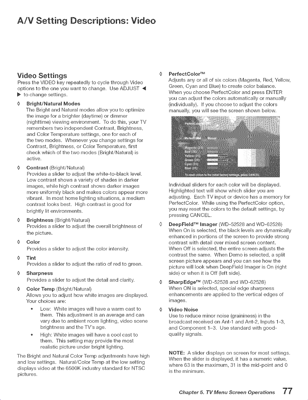
A!V Setting Descriptions: Video
Video Settings
Press the VIDEO key, repeatedly to cycle through Video
options to the one you want to change. Use ADJUST
to change settings.
0 Bright/Natural Modes
The Bright and Natural modes allow you to optimize
the image for a brighter (daytime) or dimmer
(nighttime) viewing environment. To do this, your TV
remembers two independent Contrast, Brightness,
and Color Temperature settings, one for each of
the two modes. Whenever you change settings for
Contrast, Brightness, or Color Temperature, first
check which of the two modes (Bright/Natural) is
active.
O Contrast (Bright/Natural)
Provides a slider to adjust the white-to-black level.
Low contrast shows a variety of shades in darker
images, while high contrast shows darker images
more uniformly black and makes colors appear more
vibrant. In most home lighting situations, a medium
contrast looks best. High contrast is good for
brightly lit environments.
0 Brightness (Bright/Natural)
Provides a slider to adjust the overall brightness of
the picture.
Color
Provides a slider to adjust the color intensity.
{>
{>
{>
{>
Tint
Provides a slider to adjust the ratio of red to green.
Sharpness
Provides a slider to adjust the detail and clarity.
Color Temp (Bright/Natural)
Allows you to adjust how white images are displayed.
Your choices are:
Low: White images will have a warm cast to
them. This adjustment is an average and can
vary due to ambient room lighting, video scene
brightness and the TV's age.
High: White images will have a cool cast to
them. This setting may provide the most
realistic picture under bright lighting.
The Bright and Natural Color Temp adjustments have high
and low settings. Natural/Color Temp at the low setting
displays video at the 6500K industry standard for NTSC
pictures.
PerfectOolor TM
Adjusts any or aii of six colors (Magenta, Red, Yellow,
Green, Cyan and Blue) to create color balance.
When you choose PerfectColor and press ENTER
you can adjust the colors automatically or manually
(individually). If you choose to adjust the colors
manually, you will see the screen shown below.
Individual sliders for each color will be displayed.
Highlighted text will show which slider you are
adjusting. Each TV input or device has a memory for
PerfectColor. While using the PerfectColor option,
you may reset the colors to the default settings, by
pressing CANCEL
0 DeepField TM Imager (WD-52528 and WD-62528)
When On is selected, the black levels are dynamically
enhanced in portions of the screen to provide strong
contrast with detail over mixed screen content.
When Off is selected, the entire screen adjusts the
contrast the same. When Demo is selected, a split
screen picture appears and you can see how the
picture will look when DeepField Imager is On (right
side) or when it is Off (left side).
0 SharpEdge TM (WD-52528 and WD-62528)
When ON is selected, special edge sharpness
enhancements are applied to the vertical edges of
images.
Video Noise
Use to reduce minor noise (graininess) in the
broadcast received on Ant-1 and Ant-2, Inputs 1-3,
and Component 1-3. Use standard with good-
quality signals.
NOTE: A slider displays on screen for most settings.
When the slider is displayed, it has a numeric value,
where 63 is the maximum, 31 is the mid-point and 0
is the minimum.
Chapter 5. TV Menu Screen Operations "7"7
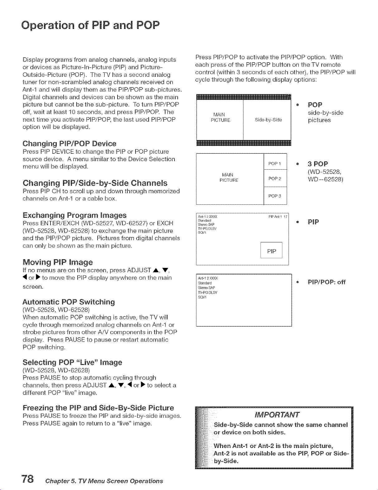
Operation of PIP and POP
DispHayprograms from anaHog channeHs, anaHog inputs
or devices as Picture-in-Picture (HP) and Picture-
Outside-Picture (POP). The TV has a second anaHog
tuner for non-scramMed anaHog channeHs received on
Antq and wHHdispHay them as the PIP/POP sub-pictures.
DigitaHchanneHs and devices can be shown as the main
picture but cannot be the sub-picture. To turn HP/POP
off, wait at Heast10 seconds, and press PBPiPOP. The
next time you activate HP/POP, the Hastused PBP/POP
option will be displayed.
Changing ProP/POP Device
Press PiP DEVICE to change the PIP or POP picture
source device. A menu similar to the Device SeHection
menu will be displayed.
Changing PUP/Side=by=Side Channels
Press PIP CH to scroll up and down through memorized
channels on Ant-1 or a cable box.
Exchanging Program mmages
Press ENTER/EXCH (WD-52527, WD-62527) or EXCH
(WD-52528, WD-62528) to exchange the main picture
and the PIP/POP picture. Pictures from digital channels
can only be shown as the main picture.
Moving PUP Umage
If no menus are on the screen, press ADJUST A V,
or _ to move the PIP display anywhere on the main
screen.
Automatic POP Switching
(WD-52528, WD-62528)
When automatic POP switching is active, the TV will
cycle through memorized analog channels on Ant-1 or
strobe pictures from other AiV components in the POP
display. Press PAUSE to pause or restart automatic
POP switching.
Semecting POP "Live" mmage
(WD-52528, WD-62628)
Press PAUSE to stop automatic cycling through
channels, then press ADJUST A V, _ or _ to select a
different POP "live" image.
Freezing the Propand Side-By-Side Picture
Press PAUSE to freeze the PIP and side-by-side images.
Press PAUSE again to return to a "live" image.
Press PIP/POP to activate the PIP/POP option. With
each press of the PIP/POP button on the TV remote
control (within 3 seconds of each other), the PIP/POP will
cycle through the following display options:
MAIN
PICTURE Side-by-Side
POP
side-by-side
pictures
MAIN
PICTURE
POP 1
POP 2
POP 3
o 3 POP
(WD-52528,
WD--62528)
A_lt- 1 2 XXXX
St_n_rd
Stereo SAP
TV-PG DLSV
SQV1
PIP Antq 17
. p(p
At/t-12 XXXX
Standard
Stereo SAP
TV-PG DLSV
SQV1
PIP/POP: off
iMPORTANT
cannot show the same channel
on both sides.
When Ant-1 or Ant=2 is the main picture,
Ant-2 is not available as the PiP, POP or Side-
by-Side.
78 Chapter 5. TV Menu Screen Operations

° r
$pecla! Featu ÷s
TV Display Formats ................................................................................ 80
Display Formats ..................................................................................... 81
Device Control with NetCommand® ..................................................... 82
Appendix A: Bypassing the V-Chip Lock .............................................. 85
Appendix B: Specifications .................................................................... 87
Appendix C: Remote ControU Programming Codes ............................ 89
Appendix D: On-Screen information DispUays ..................................... 92
Appendix E: NetCommand® SpeciaUized Device Keys ...................... 93
Appendix F: CUeaning and Service ........................................................ 94
Appendix G: FiUter CUeaning ................................................................... 95
Appendix H: Lamp Cartridge RepUacement ......................................... 96
TroubUeshooting ...................................................................................... 98
Trademark and License Information ..................................................... 103
index ......................................................................................................... 104
Wa rra nty ................................................................................................... 107
TV Display Formats
This is a widescreen TV (also known as a 16:9 TV). This shape rdiects the new types of images available from HDTV
and many DVDs. There are still many cider style narrow screen images (called 4:3 aspect ratio) you will encounter.
While there will never be a perfect solution for displaying a narrow image on a wide screen, Mitsubishi offers several
display formats to choose from.
Press FORMAT on the TV remote control to cycle through
the available display formats. The last used format for
each device will be used when you return to that device.
Note: Not all formats are available for PIP/POP.
Side=by=Side and 3 POP are only available in
Standard and Expand formats.
Standard: This is the full screen formal HDTV
signals use this formal This format is useful to display
Anamorphic DVDs that have 1.78:1 or 1.85:1 aspect
ratios. Anamorphic DVDs that have a 2.35:1 aspect ratio
wiii still display black bars at the top and bottom, but wiii
show the entire image correctly. Narrow (4:3) images will
be stretched evenly from side to side. Available for aii
signals.
DVD Definitions:
Anamorphic (or Enhanced for Widescreen TV's}:
These DVDs are recorded in a special way to properly
show widescreen images on 16:9 TV sets in the Standard
format mode. This is the recommended choice.
Non-Anamorphic (or 4:3, 1:33:1, Letterbox or Full
Screen}:
These DVDs are recorded for use with traditional shaped
TVs. They may be fuji screen (4:3 or 1:33:1) which crops
movies to fit the narrow TV, or Letterboxed which adds
black top and bottom bars.
This information may or may not be listed on the DVD
case. Some DVDs support both types of recordings.
Expand: This wiii enlarge a 4:3 picture to fiii the screen,
cropping off some of the image at the top and bottom.
This is useful to reduce the letterbox top and bottom bars
of non-anamorphic DVD. Available for analog 480i, 480p
and digital SD 4:3 signals only.
Zoom: This wiii enlarge the picture, cropping off some
of the image at each side and top and bottom. This is
useful to remove or reduce the black top and bottom bars
on anamorphic DVDs with a 2.35:1 aspect ratio. Available
for analog 480i and 480p and SD 4:3 signals only.
Stretch: This format will stretch a narrow (4:3) image
across the screen, however, there is less stretch in the
center than the sides. This wiii allow the entire narrow
image to be displayed across the screen with less
distortion than seen in the Standard format. Available for
analog 480i and 480p and SD 4:3 signals only.
SignaJ and Format Definitions:
480i Signals: Traditional analog interlaced signals from or
through Antq & 2, Inputs 1-3, Component 1-3, and HDMI.
480p Signals: Progressive-scan analog DVD signals on
Component 1-3 and HDMI.
720p & 1080i Signals: High-definition analog signals
received through Component 1-3 and HDMI. These signals
are always 16:9 (widescreen), but may have side bars
added by the broadcaster.
SD 4:3: Standard-definition narrow-screen format signals
from digitat channels and IEEE 1394 devices.
SD 16:9: Standard definition wide screen format signals
from digitaI channels and EEE 1394 devices.
Stretch Plus: Similar to stretch mode, however to
minimize distortions on the side, the picture is expanded
to crop off portions of the top and bottom. When no PIP
or POP is displayed, you can press ADJUST up or down
to vertically adjust the picture. Available for analog 480i
and 480p and SD 4:3 signals only.
Narrow: This format wiii display narrow (4:3) images in
their original shape, and add stationary black side bars to
fill the screen. Available for 480i, 480p and digital SD 4:3
signals only.
Wide Expand: Enlarges the picture, cropping some of
the image on both sides. This Expand format is useful
to remove or reduce black side bars added to narrow
images that are converted to 16:9 signals for digital
broadcasL Available for analog 1080i, 720p, digital SD
16:9 and digital HD signals.
HI): High definition wide screen format signals from digital
channels and IEEEq394 devices. These signals are always
16:9 (widescreen).
80 Chapter 6. Special Features
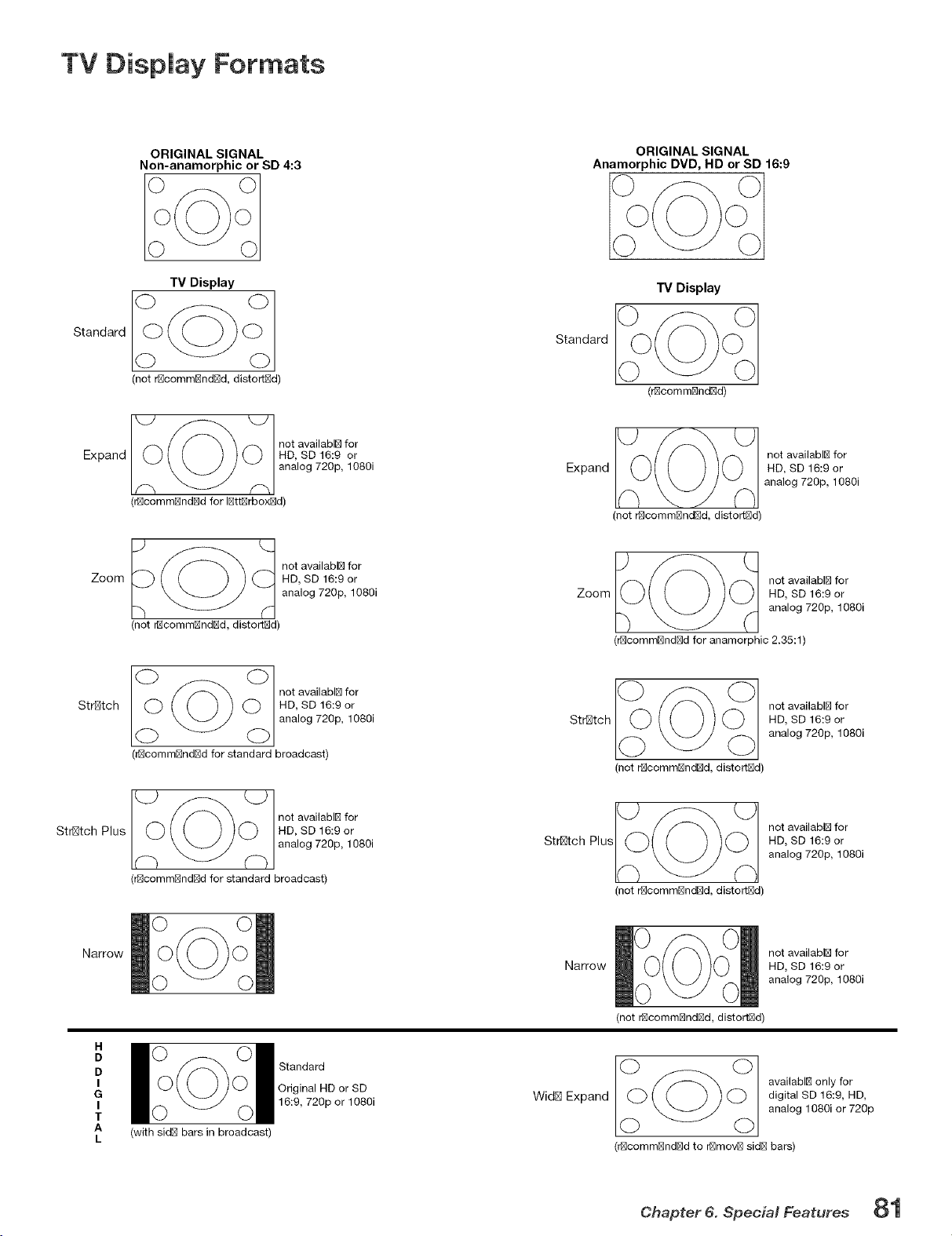
TV Display Formats
ORIGINAL SIGNAL
Non-anamorphic or SD 4:3
Standard
TV Display
(not rNcommNndNd, distortNd)
Expand
_O not availablB for
HD, SD 16:9 or
analog 720p, 1080i
(r_comm_ndE_d for IE_ttE_rbox_d)
Zoom
"_ (_ not availablB for
HD, SD 16:9 or
analog 720p, 1080i
(not r_commE_ndE_d, distortE_d)
Stretch
nota ai,a , fo
HD, SD 16:9 or
analog 720p, 1080i
(r_commBnd_d for standard broadcast)
Stretch Plus
_O not availabl_ for
HD, SD 16:9 or
analog 720p, 1080i
(r_comm_nd_d for standard broadcast)
Narrow
H
D
D
I
G
I
T
A
L
(with sidB bars in broadcast)
Standard
Original HD or SD
16:9, 720p or 1080i
ORIGINAL SIGNAL
Anamorphic DVD, HD or SD 16:9
TV Display
(r_comm_ndBd)
Standard
__0___(_ not availabl_ for
Expand HD, SD 16:9 or
analog 720p, 1080i
(not r_commBndBd, distortBd)
IO_ O 1 not availabl_ for
Zoom HD, SD 16:9 or
analog 720p, 1080i
(r_comm_nd_d for anamorphic 2.35:1)
Stretch
(not r_commE_ndE_d, distortE_d)
not availablB for
HD, SD 16:9 or
analog 720p, 1080i
Stretch Plus
not availablE_ for
HD, SD 16:9 or
analog 720p, 1080i
(not r_commE_ndE_d, distortE_d)
Narrow
not availabl_ for
HD, SD 16:9 or
analog 720p, 1080i
(not r_commBndBd, distortBd)
WidB Expand
(_(_ availabl_ only for
digital SD 16:9, HD,
analog 1080i or 720p
(r_comm_nd_d to r_mov_ sid_ bars)
Chapter 6. Special Features 81
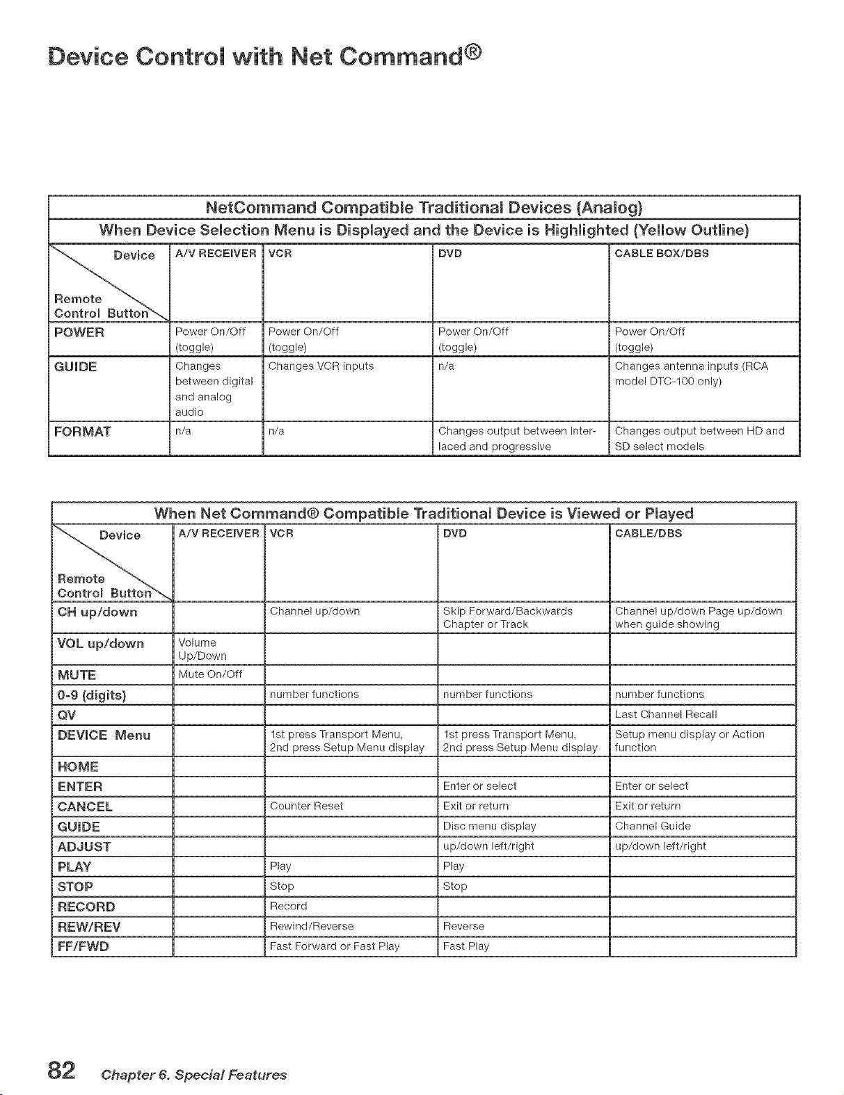
Device Control with Net Command °
NetCommand Compatibme Traditional Devices (Anamog)
When Device Selection Menu is Dispmayed and the Device is Highlighted (Yellow Outline}
e A/V RECEIVER VCR DVD CABLE BOX/DBS
POWER Power On/Off Power On/Off Power On/Off Power On/Off
(toggle) (toggle) (toggle) (toggle)
GUIDE Changes Changes VCR inputs n/a Changes antenna inputs (RCA
between digital model DTC-100 only)
and analog
audio
FORMAT n/a n/a Changes output between inter- Changes output between HD and
laced and progressive SD select models
When Net Command@ Compatible Traditional Device is Viewed or Played
A/V RECEIVER VCR DVD CABLE/DBS
OH up/down Channel up/down Skip Forward/Backwards Channel up/down Page up/down
Chapter or Track when guide showing
VOL up/down Volume
Up/Down
MUTE Mute On/Off
0-9 {digits} number functions number functions number functions
QV Last Channel Recall
DEVICE Menu 1st press Transport Menu, 1st press Transport Menu, Setup menu display or Action
2rid press Setup Menu display 2rid press Setup Menu display function
HOME
ENTER Enter or select Enter or select
CANCEL Counter Reset Exit or return Exit or return
GUIDE Disc menu display Channel Guide
ADJUST up/down left/right up/down left/right
PLAY Play Play
STOP Stop Stop
RECORD Record
REW/REV Rewind/Reverse Reverse
FF/FWD Fast Forward or Fast Play Fast Play
82 Chapter 6. Special Features
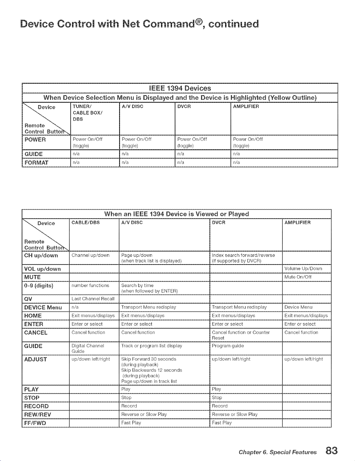
Device Control with Net Command O, continued
mEEE 1394 Devices
When Device Selection Menu is Displayed and the Device is Highlighted (Yellow Outline}
"_ Device TUNER/ A/V DISC DVCR AMPLIFIER
CABLE BOX/
DBS
Remote _
Centrom Buttor_,,
POWER Power On/Off Power On/Off Power On/Off Power On/Off
(toggle) (toggle) (toggle) (toggle)
n/a n/a n/a n/a
FORMAT n/a n/a n/a n/a
When an IEEE 1394 Device is Viewed or Played
_ CARLE/DRS A/V DISC DVCR AMPLIFmER
OH up/down Channel up/down Page up/down Index search forward/reverse
(when track list is displayed) (if supported by DVCR)
VOL up/down Volume Up/Down
MUTE Mute On/Off
0_9 (digits} number functions Search by time
(when followed by ENTER)
QV Last Channel Recall
DEVICE Menu n/a Transport Menu redisplay Transport Menu redisplay Device Menu
HOME Exit menus/displays Exit menus/displays Exit menus/displays Exit menus/displays
ENTER Enter or select Enter or select Enter or select Enter or select
CANCEL Cancel function Cancel function Cancel function or Counter Cancel function
Reset
GUIDE Digital Channel Track or program list display Program guide
Guide
ADJUST up/down left/right Skip Forward 30 seconds up/down left/right up/down left/right
(during playback)
Skip Backwards 12 seconds
(during playback)
Page up/down in track list
PLAY Play Play
STOP Stop Stop
RECORD Record Record
REW/REV Reverse or Slow Play Reverse or Slow Play
FF/FWD Fast Play Fast Play
Chapter 6. Special Features 83

84 Chapter 6. Special Features
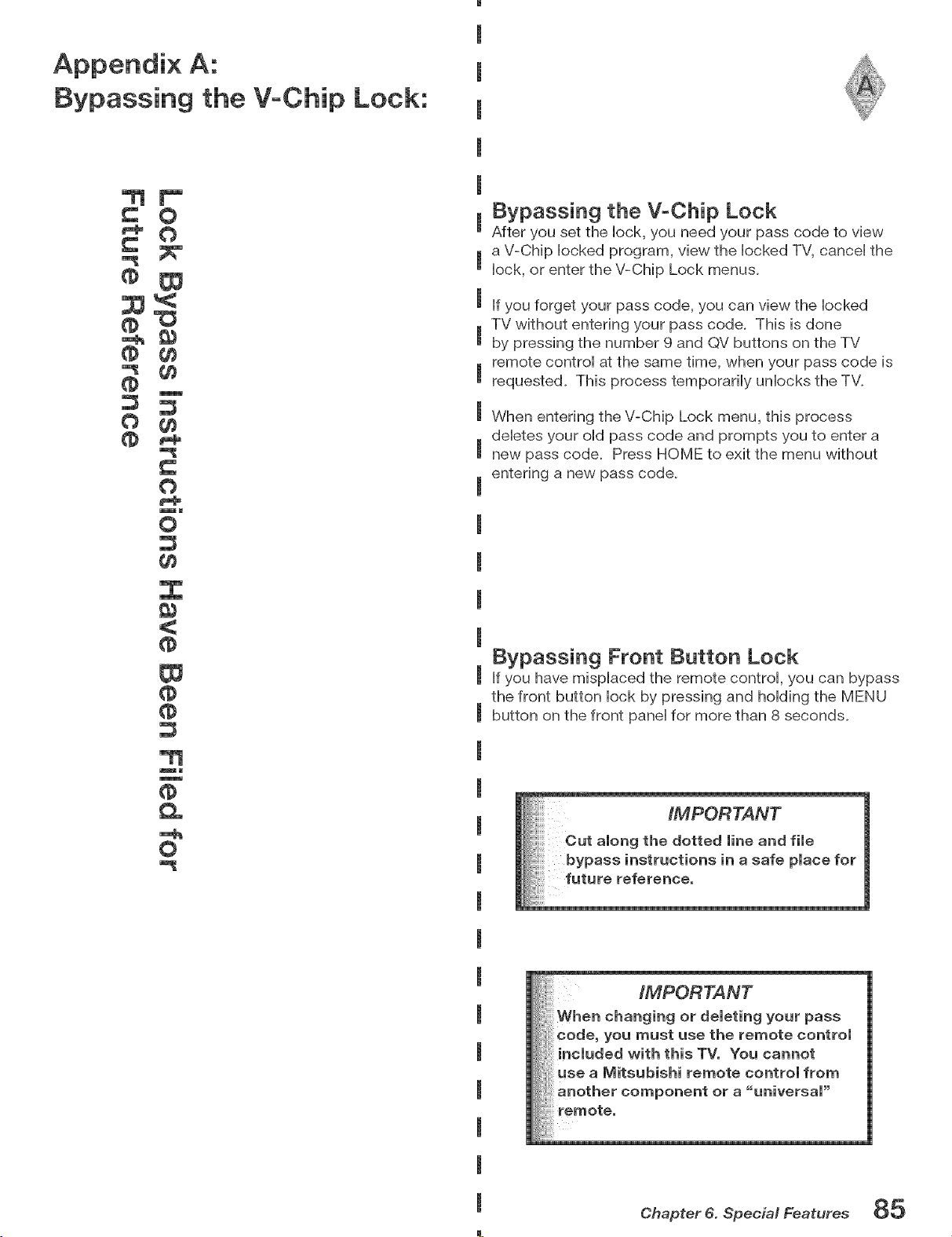
Appendix A:
Bypassing the V-Chip Lock:
O
® gg
O ¢¢
O
mm
O
gg
_)
mm
m
Q.
mh
O
Bypassing the V-Chip Lock
After you set the Hock, you need your pass code to view
a V-Chip Hocked program, view the Hocked TV, canceH the
Hock,or enter the V-Chip Lock menus.
If you forget your pass code, you can view the Hocked
TV without entering your pass code. This is done
by pressing the number 9 and QV buttons on the TV
remote controH at the same time, when your pass code is
requested. This process temporariHy unHocks the TV.
When entering the V-Chip Lock menu, this process
deHetes your oHdpass code and prompts you to enter a
new pass code. Press HOME to exit the menu without
entering a new pass code.
Bypassing Front Button Lock
If you have mispHaced the remote controH, you can bypass
the front button Hock by pressing and homing the MENU
button on the front paneHfor more than 8 seconds.
When changing or deleting your pass
code, you must use the remote control
included with this TV, You cannot
use a Mitsubishi remote control from
another component or a "universal"
....ili!i!i!!ili i
Chapter 6. Special Features 85
m

This page intentionally bJank
86 Chapter 6. Special Features
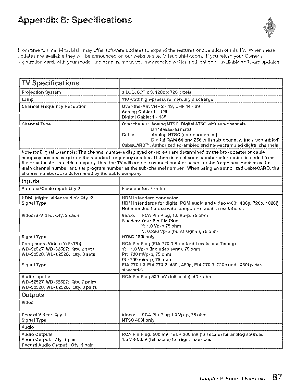
Appendix B: Specifications
From time to time, MitsubisM may offer software updates to expand the features or operation of this TV. When these
updates are avaHaMe they win be announced on our website site, MitsubishFtv.com. If you return your Owner's
registration card, with your modeH and sedan number, you may receive written notification of avaHabHesoftware updates.
TV Specifications
Projection System 3 LOB, 0.7" x 3, 1280 x 720 pixels
Lamp 110 watt high=pressure mercury discharge
Channem Frequency Reception Over-the-Air: VNF 2 - 13, UNF 14 - 69
Analog Cable: 1 - 125
Digital Cable: t - 136
Channel Type Over the Air: Anatog NTSC, Digital ATSC with sub-channels
(all 18 video formats)
Cable: Analog NTSC (non-scrambled}
Digital QAM 64 and 256 with sub-channels (non-scrambled}
CableCARDTM: Authorized scrambled and non-scrambmed digital channels
Note for Digital Channels: The channel numbers displayed on-screen are determined by the broadcaster or cable
company and can vary from the standard frequency number. If there is no channel number information included from
the broadcaster or cable company, then the TV win create a channem number based on the frequency number as the
main channel number and the program number as the sub-channel number. When using an authorized CabmeOARD, the
channem numbers are determined by the cable company.
Inputs
Antenna/Cable input: Qty 2 F connector, 76-ohm
HDMI (digital video/audio}: Qty. 2
Signal Type
Video/S-Video: Qty. 3 each
Signal Type
Component Video (Y/Pr/Pb)
WD-52527, WD-62527: Qty. 2 sets
WD-52528, WD-62528: Qty. 3 sets
Signal Type
Audio Inputs:
WD-52527, WD_62527: Qty. 7 pairs
WD-52528, WD-62528: Qty. 8 pairs
Outputs
Video
Record Video: Qty. 1 Video: RCA Pin Plug 1.0 Vp-p, 75 ohm
Signal Type NTSC 480i onmy
Audio
Audio Outputs RCA Pin Plug, 500 mV rms _+200 mV (fun scale) for analog sources.
Audio Output: Qty. 1 pair 1.5 V +_0.5 V (full scale) for digital sources.
Record Audio Output: Qty. i pair
NDMm standard connector
HDMm standards for digital PCM audio and video (480i, 480p, 720p, i080i).
Not intended for use with computer-specific resolutions.
Video: RCA Pin Plug, i.0 Vp-p, 75 ohm
S_Video: Four Pin Din Plug
Y: i,O Vp-p 75 ohm
C: 0.286 Vp_p (burst signal), 75 ohm
NTSC 480i only
RCA Pin Plug (EIA-770.3 Standard Levels and Timing)
Y: i.0 Vp-p (includes sync}, 75 ohm
Pr: 700 mVp-p, 75 ohm
Pb: 700 mVp-p, 75 ohm
EIA-770.i & EIA 770.2,480i, 480p, EIA 770.3, 720p and i080i (video
standards)
RCA Pin Plug 500 mV (fun scale), 43 k ohm
Chapter 6. Special Features 8"7
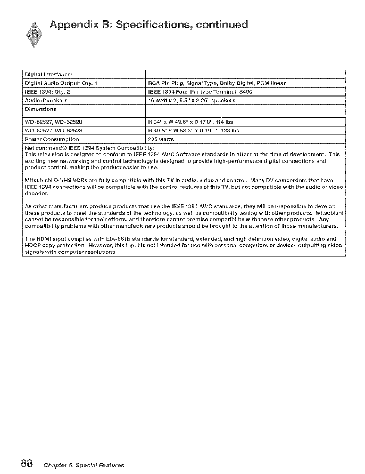
Appendix B: Specifications, continued
Digital Interfaces:
Dig[taJ Audio Output: Qty, f RCA Pin Plug, Signam Type, Domby Digital, PCM linear
IEEE f394: Qty, 2 IEEE 1394 Four-Pin type Terminal, $400
Audio/Speakers f0 watt x 2, 5,5" x 2,25" speakers
Dimensions
WD-52527, WD-52528 H 34" x W 49,6" x D 17,8", 114 Ibs
WD-62527, WD-62528 H 40,5" x W 58,3" x D 19,9", 133 robs
Power Consumpt{on 225 watts
Net commando IEEE 1394 System Compatibility:
This telev{sion is designed to conform to IEEE 4394 AV/C Software standards in effect at the time of development, This
excit{ng new networking and controm technology is designed to provide high-performance dig[ta_ connections and
product controm, making the product easier to use,
Mitsubish[ D-VHS VCRs are fully compatible w{th this TV in audio, video and control Many DV camcorders that have
IEEE f394 connections will be compatibme with the controm features of this TV, but not compatible with the audio or v{deo
decoder,
As other manufacturers produce products that use the IEEE f394 AV/C standards, they wHI be responsible to develop
these products to meet the standards of the technology, as well as compatibility testing with other products, M[tsub[shi
cannot be responsiHe for their efforts, and therefore cannot promise compatibility w{th these other products, Any
compatibility probmems with other manufacturers products shoumd be brought to the attention of those manufacturers,
The HDMI input complies with EIA=86fB standards for standard, extended, and high definition video, digital audio and
HDCP copy protection, However, this input is not intended for use with personam computers or devices outputting video
signals with computer resolutions,
88 Chapter 6. SpeciM Features
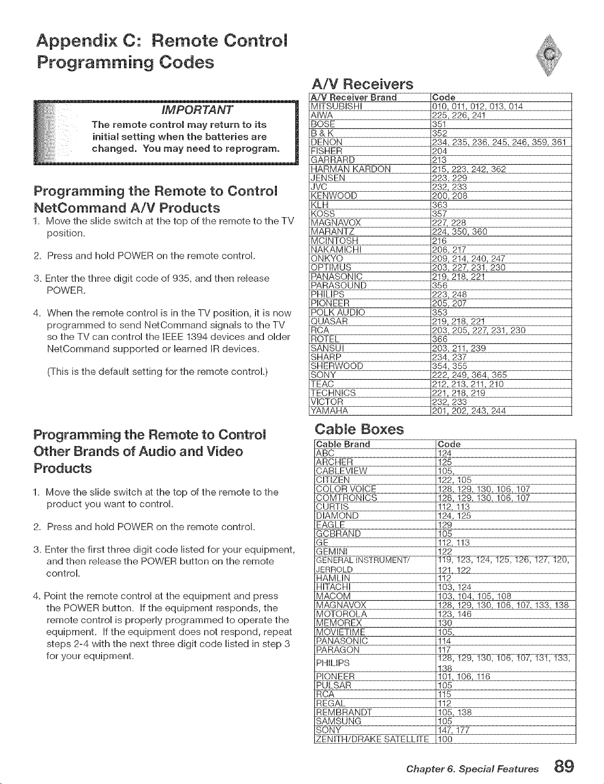
Appendix C: Remote Control
Programming Codes
Programming the Remote to Control
NetCommand A/V Products
1. Move the slide switch at the top of the remote to the TV
position.
2. Press and hold POWER on the remote control.
3_ Enter the three digit code of 935, and then release
POWER.
4_ When the remote control is in the TV position, it is now
programmed to send NetCommand signals to the TV
so the TV can control the [EEE 1394 devices and eider
NetCommand supported or learned [R devbes.
(This is the default setting for the remote controL)
Programming the Remote to Control
Other Brands of Audio and Video
Products
1_ Move the slide switch at the top of the remote to the
product you want to control.
2_ Press and hold POWER on the remote control.
3_ Enter the first three digit code listed for your equipment,
and then release the POWER button on the remote
control
4_Point the remote control at the equipment and press
the POWER button. If the equipment responds, the
remote control is properly programmed to operate the
equipmenL If the equipment does not respond, repeat
steps 2-4 with the next three digit code listed in step 3
A/V Receivers
A/V Receiver Brand
MffSUBISHI
AIWA
BOSE
B&K
DENON
FISHER
GARRARD
HARMAN KARDON
JENSEN
JVC
KENWOOD
KLH
KOSS
MAGNAVOX
MARANTZ
MCINTOSH
NAKAMICHI
ONKYO
OPTIMUS
PANASONIC
PARASOUND
PHIMPS
PIONEER
POLK AUDIO
QUASAR
RCA
ROTEL
SANSUI
SHARP
SHERWOOD
SONY
TEAC
TECHNICS
VICTOR
YAMAHA
Code
010,011,012,013,014
225,226, 241
351
352
234,235,236,245,246,359,361
204
213
215,223,242,362
223,229
232,233
200,208
363
357
227,228
224,350,360
216
206, 217
209, 214, 240, 247
203,227,231,230
219, 218, 221
356
223,248
205,207
353
219, 218, 221
203,205,227,231,230
366
203,211,239
234,237
354,355
222,249,364,365
212,213,211,210
221,218,219
232,233
201,202,243,244
Cable Boxes
Cable Brand
&BC
&RCHER
CABLEVEW
CITIZEN
COLOR VOICE
COMTRONICS
CURTIS
DIAMOND
EAGLE
GCBRAND
GE
GEMiNi
GENERAL INSTRUMENT/
JERROLD
HAMLIN
HiTACHi
MACOM
MAGNAVOX
MOTOROLA
MEMOREX
MOVIETIME
PANASONIC
PARAGON
PHILIPS
PIONEER
PULSAR
RCA
REGAL
REMBRANDT
SAMSUNG
SONY
ZENITH/DRAKE SATELLITE
Code
124
125
105,
122, 105
128, 129, 130, 106, 107
128, 129, 130, 106, 107
112, 113
124,125
129
105
112, 113
122
121,122
112
103, 124
103, 104, 105,108
128, 129, 130, 106, 107, 133, 138
123, 146
130
105,
114
117
138
101,106, 116
105
115
112
105, 138
105
147, 177
100
Chapter 6. Special Features 89
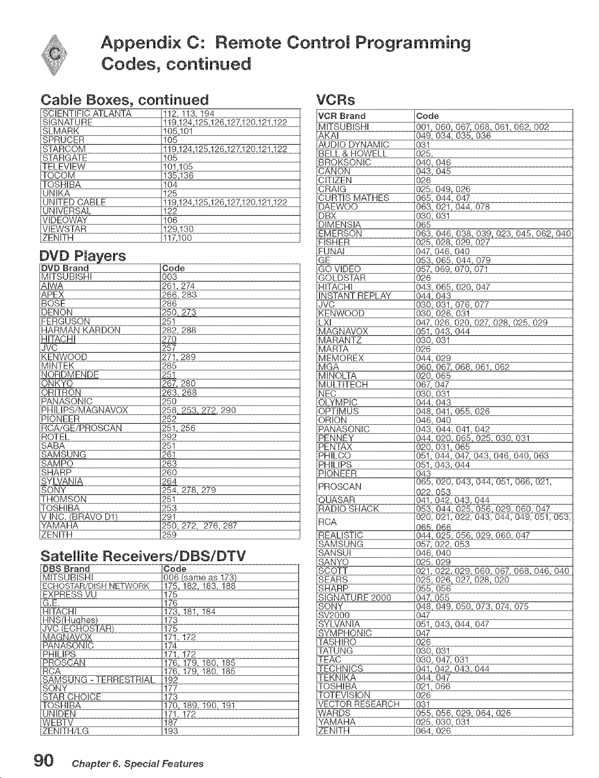
Appendix C: Remote Controm Programming
Codes, continued
CabMe Boxes, continued
SCiENTiFiC ATLANTA
SIGNATURE
SLMARK
SPRUCER
STARCOM
STARGATE
TELEVIEW
TOCOM
TOSHIBA
UNIKA
UNITED CABLE
UNIVERSAL
VIDEOWAY
VIEWSTAR
ZENITH
112, 113, 194
119,124,125,126,127,120,121,122
105,101
105
119,124,125,126,127,120,121,122
105
101,105
135,136
104
125
119,124,125,126,127,120,121,122
122
106
129,130
117,100
DVD Brand
MITSUBISHI
AIWA
APEX
BOSE
DENON
EERGUSON
HARMAN KARDON
HiTACHi
JVC
KENWOOD
MINTEK
NORDMENDE
ONKYO
ORITRON
PANASONIC
PHILIPS/MAGNAVOX
PIONEER
RCA/GE/PROSCAN
ROTEL
SABA
SAMSUNG
SAMPO
SHARP
SYLVANIA
SONY
THOMSON
TOSHIBA
V INC. (BRAVO D1)
YAMAHA
ZENITH
Code
003
261,274
266,283
286
2502=8Z_73
251
282,288
27O
257
271,289
285
251
267,280
263,268
250
258 253.272,290
252
251,256
292
251
261
263
260
264
254,278,279
251
253
291
250,272, 276,287
259
Satellite Receivers/DBS/DTV
DBS Brand
MITSUBISHI
ECHOSTAR/DISH NETWORK
EXPRESS VU
G.E.
HiTACHi
HNS(Huqhes}
JVC (ECHOSTAR)
MAG N AVOX
PANASON IC
PHILIPS
PROSCAN
RCA
SAMSUNG - TERRESTRIAL
SONY
STAR CHOICE
TOSHIBA
UNIDEN
WEBTV
ZENITH/LG
Code
006(same as 173)
175,182,183,188
175
176
173,181,184
173
175
171,172
174
17!,172
176,!79,180,185
176,179,180,185
192
177
173
170,189,190,191
171,172
187
193
VORs
VCR Brand
MITSUBISHI
AKAI
AUDIO DYNAMIC
BELL & HOWELL
BROKSONIC
CANON
CiTiZEN
Code
i001,060,
i049,034,
031
i025,
i040,046
i043,045
026
LXI
MAGNAVOX
MARANTZ
MARTA
MEMOREX
MGA
MINOLTA
MULTITECH
NEC
OLYMPIC
OPTIMUS
ORION
PANASONIC
PENNEY
PENTAX
PHILCO
PHILIPS
PIONEER
PROSCAN
QUASAR
RADIO SHACK
RCA
REALiSTiC
SAMSUNG
SANSUI
SANYO
SCOTT
CRAIG 025,
CURTIS MATHES 065,
DAEWOO 063,
DBX 030,
DIMENSIA 065
EMERSON 063,
FISHER 025,
EUNAI 047,
GE 053,
GQ VIDEO 057,
GOLDSTAR 026
HiTACHi 048,
iNSTANT REPLAY 044,
JVC 030_
KENWOOD 030,
047,
051,
030,
026
044, 029
060, 067,
020_ 065
067, 047
030,
044,
048,
046,
043,
044,
020_
051,044,
051,043,
043
065, 020,
022, 053
067_068,061,062,002
035,036
049,026
044,047
021,044,078
031
046,038,039,023,045,062,040
028,029,027
046,040
065,044,079
069,070,071
065,020,047
O43
031,076,077
026,031
026,020,027,028,025,029
043,044
031
068,061,062
031
O43
041,055,026
O4O
044,041,042
020,065,025,030,031
031,065
047,043,046,040,063
O44
043,044,051,066,021,
i041,042,043,044
i053,044,025,056,029,060,047
i020,021,022,043,044,049,051,053,
i065,066
i044,025,056,029,060,047
1057,022,053
i046,040
i025,029
021,
SEARS 025,
SHARP O55,
SIGNATURE 2000 047,
SONY 048,
022,029,060,067,068,046,040
026,027_028,020
O56
O55
049, 050, 073, 074, 075
043,044,047
031
047,031
042,043,044
O47
066
056,029,064,026
030,031
026
i047
i051,
047
026
030,
030,
041,
044,
021,
026
031
055,
025,
064,
SV2000
SYLVANIA
SYMPHONIC
TASHIRO
TATUNG
TEAC
TECHNICS
TEKNIKA
TOSHIBA
TOTEVISION
VECTOR RESEARCH
WARDS
YAMAHA
ZENITH
90 Chapter 6. Special Features
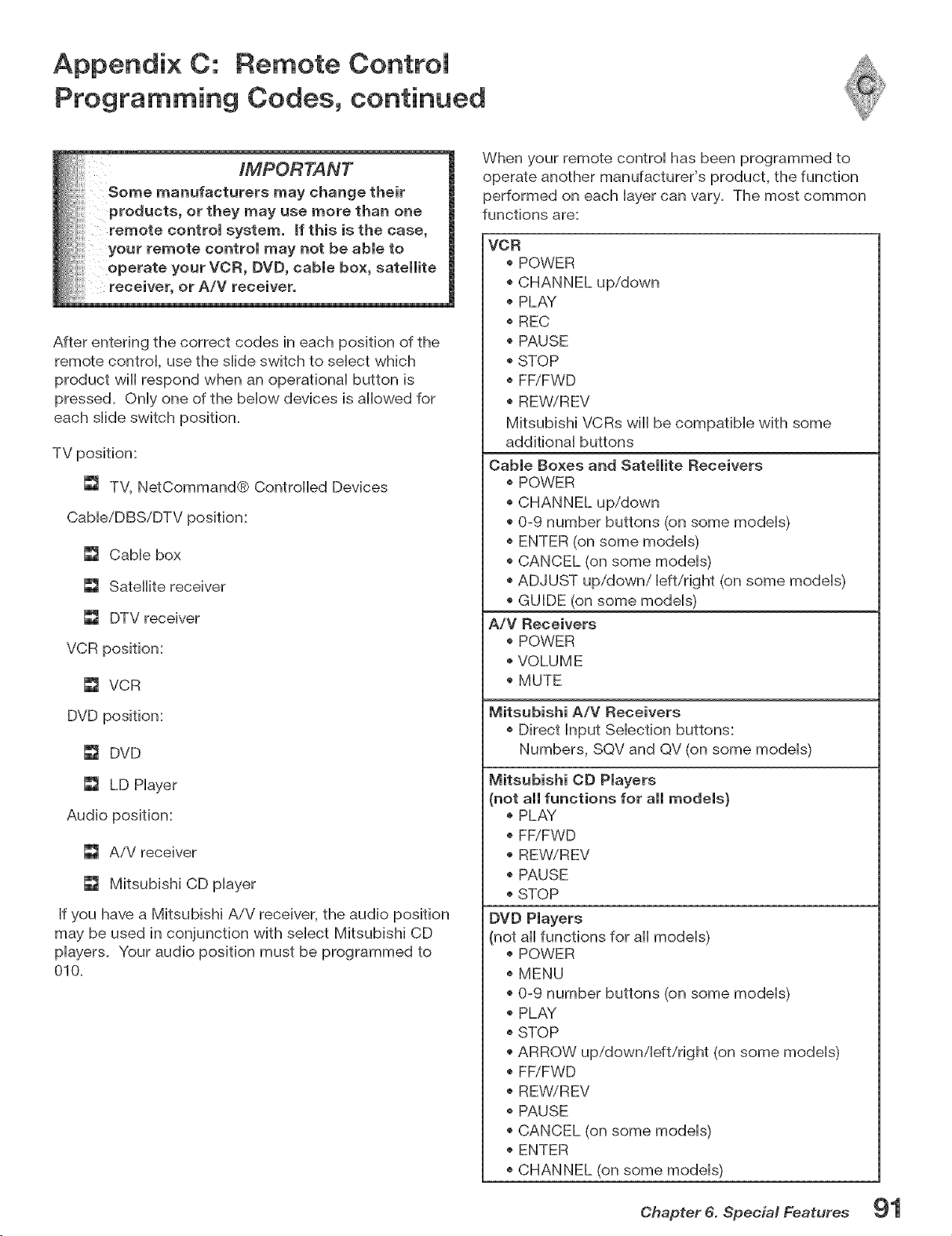
Appendix C: Remote Controm
Programming Codes, continued
IMPORTANT
Some manufacturers may change their
products, or they may use more than one
remote control system, mfthis is the case,
your remote control may not be able to
operate your VCR, DVD, cable box, satellite
receiver, or A/V receiver.
After entering the correct codes in each position of the
remote controH, use the sHideswitch to seHect which
product will respond when an operafionaH button is
pressed. OnHyone of the bellow devices is allowed for
each sHideswitch position.
TV position:
[] TV, NetCommand® Controlled Devices
Cable/DBSiDTV position:
[] Cable box
[] Satellite receiver
_J DTV receiver
VCR position:
[] VCR
DVD position:
[] DVD
_1 LD Player
Audio position:
[] AiV receiver
[] Mitsubishi CD player
If you have a Mitsubishi AiV receiver, the audio position
may be used in conjunction with select Mitsubishi CD
players. Your audio position must be programmed to
010.
When your remote control has been programmed to
operate another manufacturer's product, the function
performed on each layer can vary. The most common
functions are:
VCR
POWER
CHANNEL up/down
PLAY
REC
PAUSE
STOP
FF/FWD
REWiREV
Mitsubishi VCRs wiii be compatible with some
additional buttons
Cable Boxes and Satellite Receivers
POWER
CHANNEL up/down
0-9 number buttons (on some models)
ENTER (on some models)
CANCEL (on some models)
ADJUST up/down/left/right (on some models)
GUIDE (on some models)
A/V Receivers
POWER
VOLUME
MUTE
Mitsubishi A/V Receivers
Direct Input Selection buttons:
Numbers, SQV and QV (on some models)
Mitsubishi CD Players
(not all functions for all models}
PLAY
FF/FWD
REW/REV
PAUSE
STOP
DVD Players
(not all functions for all models)
POWER
MENU
0-9 number buttons (on some models)
PLAY
STOP
ARROW up/down/left/right (on some models)
FFiFWD
REWiREV
PAUSE
CANCEL (on some models)
ENTER
CHANNEL (on some models)
Chapter 6. Special Features 91
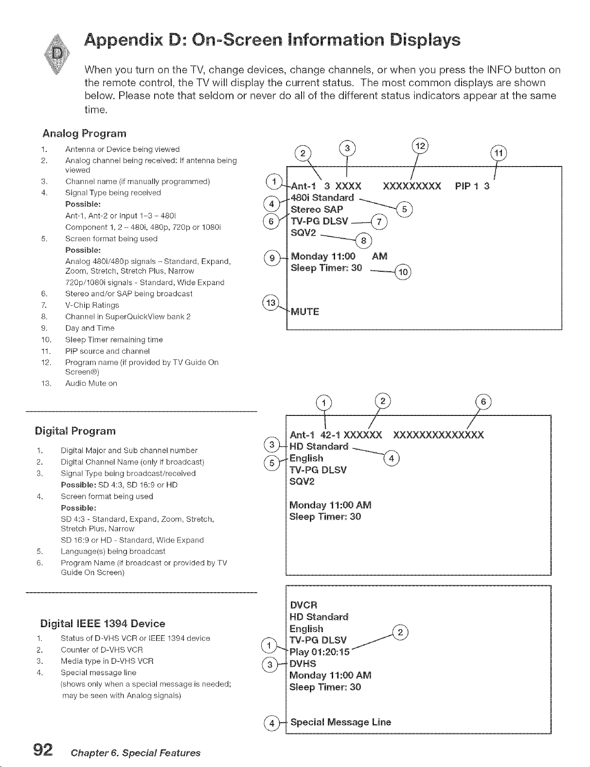
Appendix D: On-Screen Information Dispmays
When you turn on the TV, change devices, change channels, or when you press the INFO button on
the remote controU, the TV will dispUay the current status. The most common dispUays are shown
beUow. PRease note that seUdom or never do aH of the different status indicators appear at the same
time.
Analog Program
1. Antenna or Device being viewed
2. Analog channel being received: If antenna being
viewed
name (if manually programmed) (t_
3. Channel
4. Signal Type being received
Possible: @'_
Ant-l, Ant-2 or input 1-3 - 480i _-",_,
\CJ
Component 1, 2 - 480i, 480p, 720p or 1080i
5. Screen format being used
PossibBe:
fZ",,
Analog 480i/480p signals - Standard, Expand, (_._
Zoom, Stretch, Stretch Plus, Narrow
720p/1080i signals - Standard, Wide Expand
6. Stereo and/or SAP being broadcast
7. V-Chip Ratings
8. Channel in SuperQuickView bank 2
9. Day and Time
10. Sleep Timer remaining time
11. PiP source and channel
12. Program name (if provided by TV Guide On
Screen¢_))
13. Audio Mute on
Digital Program
1= Digital Major and Sub channel number
2= Digital Channel Name (only if broadcast)
3. Signal Type being broadcast/received
Possible: SD 4:3, SD 16:9 or HD
4. Screen format being used
Possible:
SD 4:3 - Standard, Expand, Zoom, Stretch,
Stretch Plus, Narrow
SD 16:9 or HD- Standard, Wide Expand
5. Language(s) being broadcast
6. Program Name (if broadcast or provided by TV
Guide On Screen)
.Ant=l 3 XXXX XXXXXXXXX
480i Standard
Stereo SAP --_"_--'_-'(_
TV-PG DLSV
SQV2
Monday 11:00 AM
Sleep Timer: 30 _----_n-'_
'MUTE
Ant-1 42-1 XXXXXX XXXXXXXXXXXXXX
, HD Standard ...__._f.__
_J
TV=PG DLSV
SQV2
Monday 11:00 AM
Sleep Timer: 30
1.
2.
3.
4.
Digital (EEE 1394 Device
Status of D-VHS VCR or IEEE 1394 device
Counter of D-VHS VCR
Media type in D-VHS VCR
Special message line
(shows only when a special message is needed;
may be seen with Analog signals)
DVCR
HD Standard
English
TV=PG DLSV / "-1
"Play 01:20:15
' DVHS
Monday 11:00 AM
Sleep Timer: 30
. Special Message Line
92 Chapter 6. Special Features
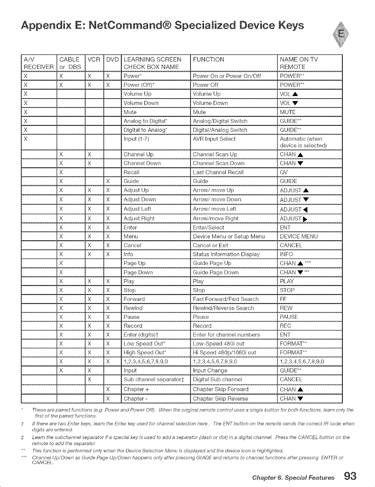
Appendix E: NetCommand® Speciamized Device Keys
AiV CABLE VCR DVD LEARNING SCREEN
RECEIVER or DBS CHECK BOX NAME
X X X X Power*
X X X X Power (Off)*
X Volume Up
X Volume Down
X Mute
X Analog to Digital*
X Digital to Analog*
X input (1-7)
X X Channel Up
X X Channel Down
X Recall
X X Guide
X X X Adjust Up
X X X Adjust Down
X X X Adjust Left
X X X Adjust Right
X X X Enter
X X X Menu
X X X Cancet
X X X Info
X Page Up
X Page Down
X X X Play
X X X Stop
X X X Forward
X X X Rewind
X X X Pause
X X X Record
X X X Enter (digits)t
X X X Low Speed Out*
X X X High Speed Out*
X X X 1,2,3,4,5,6,7,8,9,0
X X input
X Sub channet separator:j:
X Chapter +
X Chapter -
FUNCTION
Power On or Power On/Off
Power Off
Volume Up
Volume Down
Mute
Analog/Digital Switch
Digital/Analog Switch
AVR input Select
Channel Scan Up
Channel Scan Down
Last Channel Recall
Guide
Arrow/move Up
Arrow/move Down
Arrow/move Left
Arrow/move Right
Enter/Select
Device Menu or Setup Menu
Cancel or Exit
Status information Display
Guide Page Up
Guide Page Down
Play
Stop
Fast Forward/Fwd Search
Rewind/Reverse Search
Pause
Record
Enter for channel numbers
Low-Speed 480i out
Hi Speed 480p/1080i out
1,2,3,4,5,6,7,8,9,0
input Change
Digital Sub channel
Chapter Skip Forward
Chapter Skip Reverse
NAME ON TV
REMOTE
POWER**
POWER**
VOL •
VOL •
MUTE
GUIDE**
GUIDE**
Automatic (when
device is selected)
CHAN •
CHAN •
QV
GUIDE
ADJUST •
ADJUST •
ADJUST
ADJUST _
ENT
DEVICE MENU
CANCEL
INFO
CHAN • ***
CHAN • *_
PLAY
STOP
FF
REW
PAUSE
REC
ENT
FORMAT**
FORMAT**
1,2,3,4,5,6,7,8,9,0
GUIDE**
CANCEL
CHAN •
CHAN •
These are paired functions (e.g. Power and Power Off). When the original remote control uses a single button for bet,@functions, learn only the
first of the paired functions.
? If there are two Enter keys, learn the Enter key used for channel selection here. The ENT button on the remote sends the correct IR code when
digits are entered.
$ Learn the subchannel separator if a special key is used to add a separator (dash or dot) in a digital channel. Press the CANCEL button on the
remote to add the separator
** This function is performed only when the Device Selection Menu is displayed and the device icon is highlighted.
*** Channel Up/Down as Guide Page Up/Down happens only after pressing GUIDE and returns to channel functions after pressing ENTER or
CANCEL.
Chapter 6. Special Features 93
Appendix F: Cmeaning and Service
Normally, light dusting with a dry, non-scratching duster wiii keep your TV clean. If cleaning beyond this is needed,
please use the following guidelines:
First, turn off the TV and unplug the power cord from the power outleL
Top and Sides of the TV:
Gently wipe down your TV with a soft, non-abrasive cloth such as cotton flannel or a clean cloth diaper, lightly
moistened with water. Dry with a second dry, soft, non-abrasive cloth.
For oily dirt, add a few drops of mild liquid detergent, such as dishwashing detergent to the water used to moisten
the cloth. Rinse with a second cloth moistened only with water. Dry with a third dry, soft, non-abrasive cloth.
o Follow the instructions for the top and sides, but wipe gently in an up and down motion, following the grooves in the
screen.
o Clean the entire screen evenly, not just sections of the screen.
Do not allow liquid to drip down the grooves of the screen, as some liquid may enter the TV between the screen and
the screen frame.
You may purchase Mitsubishi Screen Cleaner, part number CLEANERWSS, by caiiing (800) 558-727&
GeneraJ Cleaning Warnings:
DO NOT allow liquid to enter the TV through the ventilation dots or any crevice.
o DO NOT use any strong or abrasive cleaners as these can scratch the surfaces.
DO NOT use any cleaners with ammonia, bleach, alcohol, benzine, or thinners as these can dull the surfaces.
DO NOT spray liquids or cleaners directly on the TV's surfaces.
DO NOT scrub or rub the TV harshly. Wipe it gently.
Service
If you are unable to correct a problem with your TV, consult your Mitsubishi dealer or a Mitsubishi Authorized Warranty
Service Center.
o DO NOT adjust any controls other than those described in this Owner's Guide.
o DO NOT remove the protective back cover of your TV.
Menus not described and shown in this owner's guide are designed for Factory use and for Authorized Service
Personnel. Damage caused to the TV by non-authorized changes or changes to these menus made by non-authorized
persons are not covered under warranty.
94 Chapter 6. Special Features
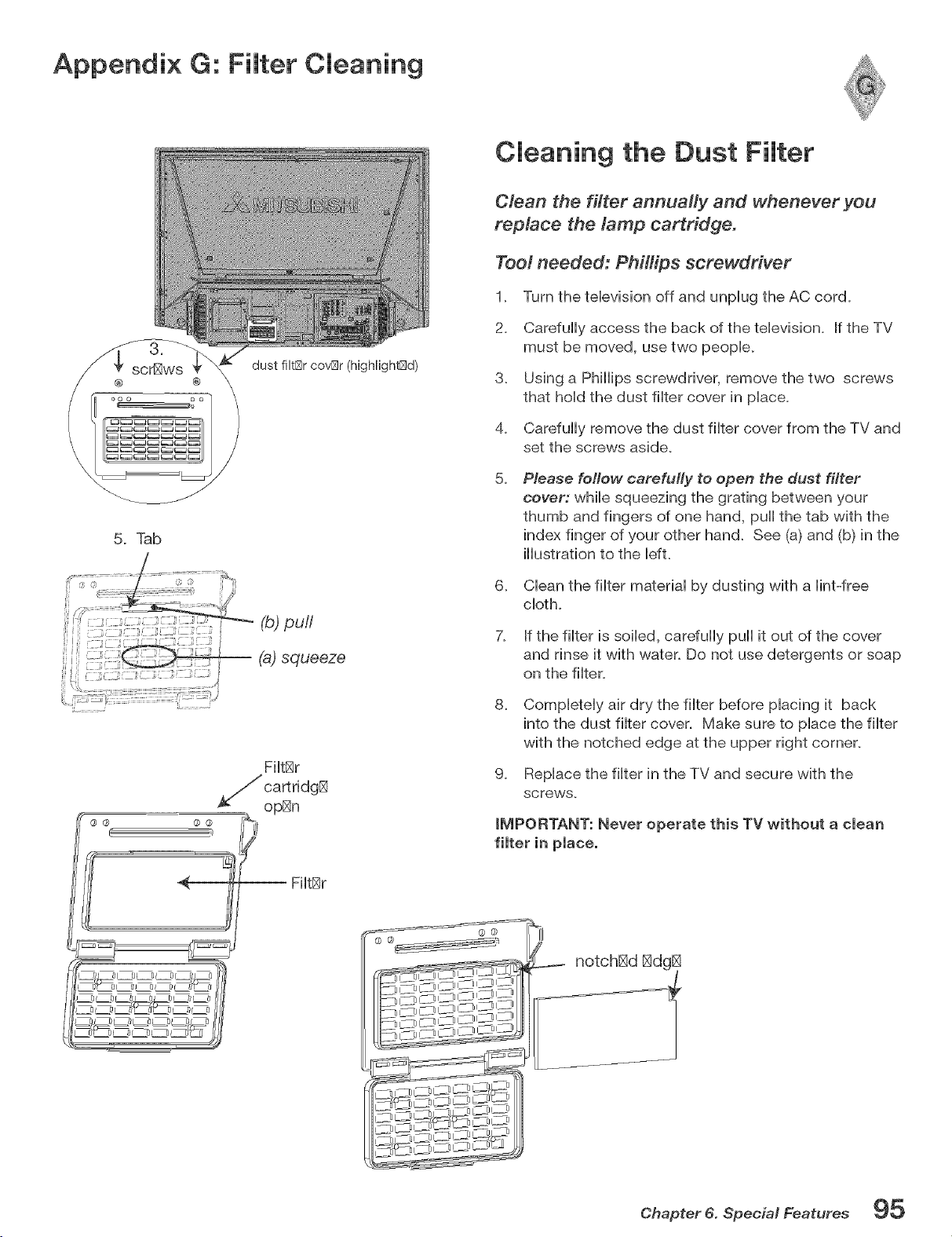
Appendix G: Fimter Cmeaning
dust filt[Sr cov[Sr (high%h@d)
® \
5. Tab
2
(@puff
;, J i_ {
/ squ÷ozo
i ": 2 ................................_!
{,
FHt[_r
Cleaning the Dust Filter
Clean the filter annually and whenever you
replace the tamp cartridge.
Toot needed: Phillips screwdriver
1. Turn the television off and unplug the AC cord.
2. Carefully access the back of the television. If the TV
must be moved, use two people.
3. Using a Phillips screwdriver, remove the two screws
that hold the dust filter cover in place.
4. Carefully remove the dust filter cover from the TV and
set the screws aside.
5.
Please follow carefully to open the dust filter
cover: while squeezing the grating between your
thumb and fingers of one hand, pull the tab with the
index finger of your other hand. See (a) and (b) in the
illustration to the Idt.
6. Clean the filter material by dusting with a lint-free
cloth.
7. If the filter is soiled, carefully pull it out of the cover
and rinse it with water. Do not use detergents or soap
on the filter.
8.
g.
Completely air dry the filter before placing it back
into the dust filter cover. Make sure to place the filter
with the notched edge at the upper right corner.
Replace the filter in the TV and secure with the
screws.
iMPORTANT: Never operate this TV without a clean
@ @
Chapter 6. Special Features 95

Appendix H: Lamp Cartridge Replacement
Before you replace the lamp cartridge please note the following:
CAUT(ON: (f the te(evision is on, press POWER to turn it off. AHow the te(evision to coo( for
one hour before attempting to repmace the marnp cartridge.
LAMP MFE
The light source for this television is a lamp, which is part of a lamp cartridge assembiy, The actual life of the lamp
in this television can vary, based on the lamp itself, the air temperature around the TV while it is operating, and your
viewing patterns, Warmer air or poor ventilation shortens the lamp life, as does turning the television on and off
frequently,
When the end of the lamp's life is approaching, the TV displays a warning message for one minute when you power on
the TV. The message will reappear the next five times you turn on the TV. After you change the lamp cartridge, you
must reset the lamp reminder through the TV Setup menu. Otherwise, the warning message will appear again too soon.
Mitsubishi warrants the lamp for one (1) year from date of the original purchase at retail. It is likely, however, that the
lamp wiii last significantly longer than this.
TO ORDER A NEW LAMP:
f While Under Warranty
Caii (800) 332-2119. Please have model number,
serial number, and TV purchase date available.
After Warranty
Call (800) 553-7278. Order lamp part number
915P028010.
Do not remove the lamp cartridge immediately after turning off the television. You may get burned because of the
lamp's high temperature. Allow the television to cool for one hour before attempting to replace the lamp cartridge.
Do not remove the lamp cartridge except when replacing iL Careless treatment can result in injury or fire.
Do not touch the lamp glass elemenL It may be very hot and break, causing injuries or burns.
Be sure not to insert any metal or flammable object into the lamp cartridge opening, as it may cause fire or electrical
shock. If any object is inserted into the opening, unplug the AC cord of the TV and contact your dealer for service.
Install the lamp cartridge securely. Failure to do so may cause a fire.
Do not touch the lamp glass elements. Oils from your fingers may cause premature lamp failure.
The lamp in this product contains mercury. Disposal of mercury may be regulated due to environmental considerations.
For disposal or recycling information, please contact your local authorities or the Electronic Bndustries Alliance at:
wwwoeiaeoorg_
96 @hapter 6. Special Features

Appendix H: Lamp Cartridge Replacement, continued
Replacing the Lamp Cartridge
Too[ needed: PhHHps screwdriver
1. Turn th_ t_l_vision off and unplug th_ AC cord.
ThB TV should bB off for at IBast onB hour to
allow thB cur_nt lamp to cool.
lamp cartridg[_ partial (higNight[_d)
,
,
Ca_fully accBss thB back of thB tBIBvision. If
thB TV must bB movBd, usB two pBopIB.
Using a phillips scr_wdrivBr, r_movB thB two
screws on thB right sidB that hold thB _cBssBd
plastic covBr in placB.
4. RBmovB thB plastic covBr and sBt asidB with
thB screws.
,
AftBr _moving thB covBr, you will bB ablB to
sBB thB lamp cartridgB. With thB scr_wdrivBr,
complBtBly IoosBn thB two screws of thB
cartridgB (onB on thB bottom IBft cornBr and
onB on thB top right comBO.
The two screws cannot be completely
removed.
6. GBntly grasp thB plastic handlB and pull
straight out (towards you).
lamp carh idgB (highlightBd)
,
,
[nsBrt thB nBw lamp cartridgB sBcur_ly. Do not
touch thB glass surfacB of thB cartridge.
With thB scr_wdrivBr, tightBn thB screws on thB
lamp cartridgB.
9. RBplacB thB plastic covBr and screws.
10.
RBsBt thB lamp r_mindBr mBssagB. Press TV
MENU, sBIBct thB SBtup mBnu, and thBn sBIBct
thB Lamp RBmindBr option to _sBt thB hours
to z_ro.
To order a new _amp under warranty, call (800) 332-2119. P_ease have mode_ number,
seria_ number and TV purchase date available. To order a new _amp after warranty, call
(800} 553-7278 and order _amp part number 915P028010.
Chapter 6. Special Features 9"7
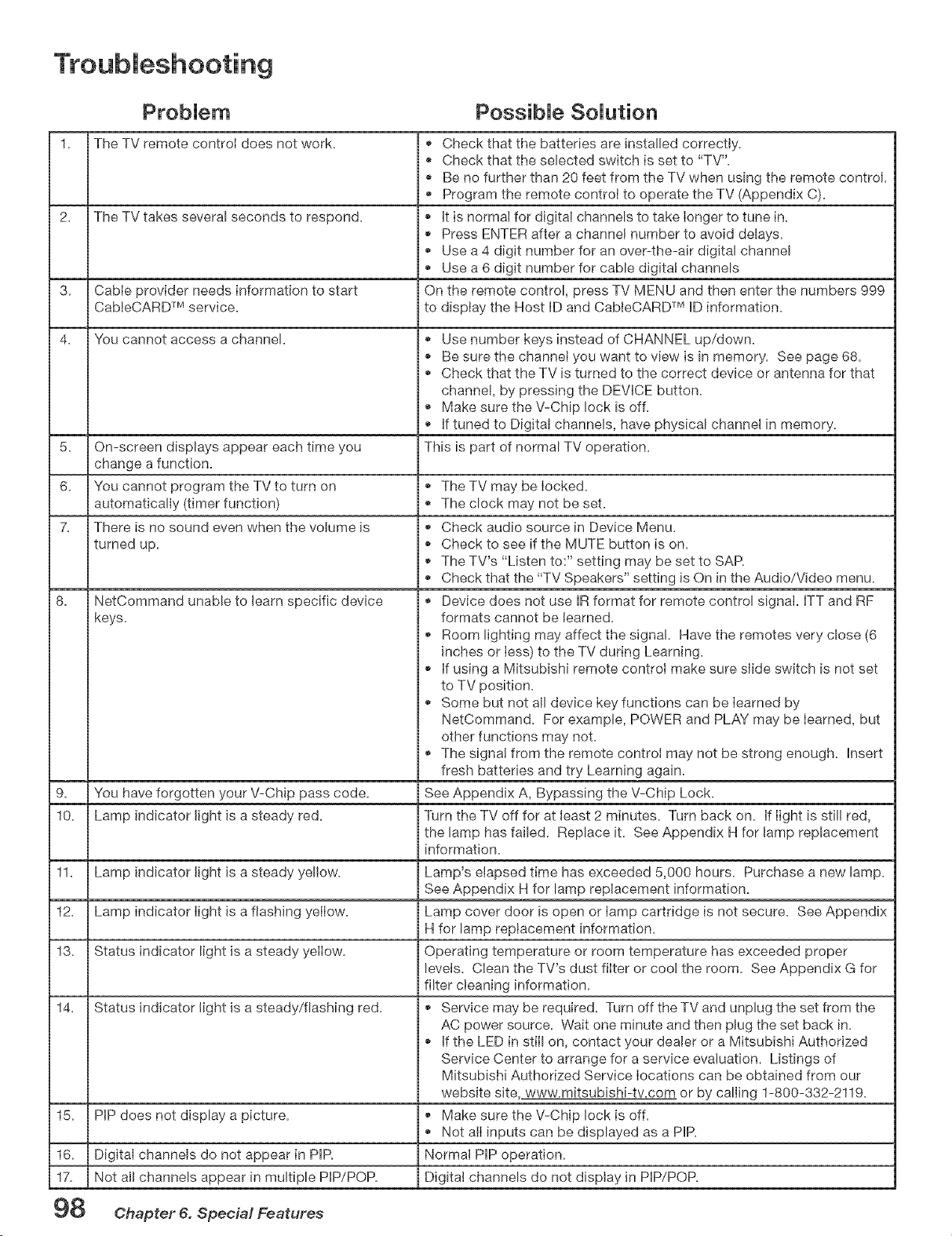
1. The TV remote control does not work.
2. The TV takes several seconds to respond.
3.
4.
PossibJe SoJution
Cable provider needs information to start
CableCARD TM service.
You cannot access a channek
5. On-screen displays appear each time you
change a function.
6. You cannot program the TV to turn on
automatically (timer function)
7. There is no sound even when the volume is
turned up.
8. NetCommand unable to learn specific device
keys.
9. You have forgotten your V-Chip pass code.
10. Lamp indicator light is a steady red.
11. Lamp indicator light is a steady yellow.
12. Lamp indicator light is a flashing yellow.
13. Status indicator light is a steady yellow.
14. Status indicator light is a steady/flashing red.
15.
16.
17.
98
PiP does not display a picture.
Digital channels do not appear in PIR
Not all channels appear in multiple PIP/POP.
Check that the batteries are installed correctly.
Check that the selected switch is set to "TV".
Be no further than 20 feet from the TV when using the remote control.
Program the remote control to operate the TV (Appendix C).
It is normal for digital channels to take longer to tune in.
Press ENTER after a channel number to avoid delays.
Use a 4 digit number for an over-the-air digital channel
Use a 6 digit number for cable digita! channels
On the remote control, press TV MENU and then enter the numbers 999
to display the Host ID and CabteCARD TM ID information.
Use number keys instead of CHANNEL up/down.
Be sure the channel you want to view is in memory. See page 68.
Check that the TV is turned to the correct device or antenna for that
channel, by pressing the DEVICE button.
Make sure the V-Chip lock is off.
If tuned to Digital channels, have physical channel in memory.
This is part of normal TV operation.
The TV may be locked.
The clock may not be set.
Check audio source in Device Menu.
Check to see if the MUTE button is on.
The TV's "Listen to:" setting may be set to SAR
Check that the "TV Speakers" setting is On in the Audio/Video menu.
Device does not use IR format for remote control signal. ITT and RE
formats cannot be learned.
Room lighting may affect the signal. Have the remotes very close (6
inches or less) to the TV during Learning.
If using a Mitsubishi remote control make sure slide switch is not set
to TV position.
Some but not all device key functions can be learned by
NetCommand. For example, POWER and PLAY may be learned, but
other functions may not.
The signal from the remote control may not be strong enough. Insert
fresh batteries and try Learning again.
See Appendix A, Bypassing the V-Chip Lock.
Turn the TV off for at least 2 minutes. Turn back on. If light is still red,
the lamp has failed. Replace it. See Appendix H for lamp replacement
information.
Lamp's elapsed time has exceeded 5,000 hours. Purchase a new lamp.
See Appendix H for lamp replacement information.
Lamp cover door is open or lamp cartridge is not secure. See Appendix
H for lamp replacement information.
Operating temperature or room temperature has exceeded proper
levels. Clean the TV's dust filter or cool the room. See Appendix G for
filter cleaning information.
Service may be required. Turn off the TV and unplug the set from the
AC power source. Wait one minute and then plug the set back in.
If the LED in still on, contact your deaJer or a Mitsubishi Authorized
Service Center to arrange for a service evaluation. Listings of
Mitsubishi Authorized Service locations can be obtained from our
website site www.mitsubishi-tv.com or by calling 1-800-332-2119.
Make sure the V-Chip lock is off.
Not all inputs can be displayed as a PIP.
Normal PIP operation.
Digital channels do not display in PIP/POP.
Chapter 6. Special Features
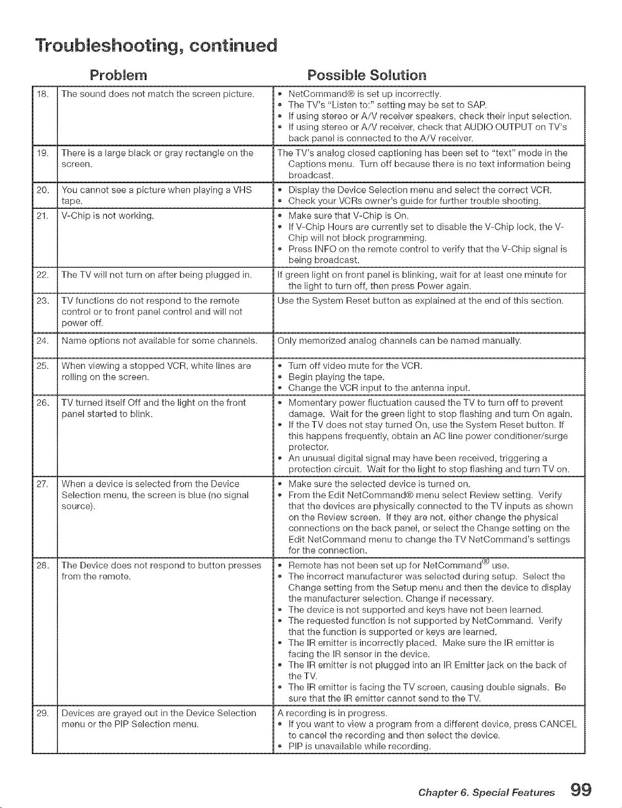
Troubleshooting, continued
18. The sound does not match the screen picture.
19.
20,
21,
22,
23,
24,
25,
26.
27.
28.
29.
PossibJe SoJution
There is a large black or gray rectangle on the
screen.
You cannot see a picture when playing a VHS
tape.
V-Chip is not working.
The TV will not turn on after being plugged in.
TV functions do not respond to the remote
control or to front panel control and will not
power off.
Name options not available for some channels.
When viewing a stopped VCR, white lines are
rolling on the screen.
TV turned itself Off and the light on the front
panel started to blink.
When a device is selected from the Device
Selection menu, the screen is blue (no signa!
source).
The Device does not respond to button presses
from the remote.
Devices are grayed out in the Device Selection
menu or the PIP Selection menu.
® NetCommand® is set up incorrectly.
® The TV's "Listen to:" setting may be set to SAP.
If using stereo or A/V receiver speakers, check their input selection.
® If using stereo or A/V receiver, check that AUDIO OUTPUT on TV's
back panel is connected to the A/V receiver.
The TV's analog closed captioning has been set to "text" mode in the
Captions menu. Turn off because there is no text information being
broadcast.
® Display the Device Selection menu and select the correct VCR.
® Check your VCRs owner's guide for further trouble shooting.
® Make sure that V-Chip is On.
® If V-Chip Hours are currently set to disable the V-Chip lock, the V-
Chip will not block programming.
® Press INFO on the remote control to verify that the V-Chip signal is
being broadcast.
If green light on front panel is blinking, wait for at least one minute for
the light to turn off, then press Power again.
Use the System Reset button as explained at the end of this section.
Only memorized analog channels can be named manually.
® Turn off video mute for the VCR.
® Begin playing the tape.
Change the VCR input to the antenna input.
® Momentary power fluctuation caused the TV to turn off to prevent
damage. Wait for the green light to stop flashing and turn On again.
® if the TV does not stay turned On, use the System Reset button, if
this happens frequently, obtain an AC line power conditioner/surge
protector.
® An unusual digita! signal may have been received, triggering a
protection circuit. Wait for the light to stop flashing and turn TV on.
® Make sure the selected device is turned on.
From the Edit NetCommand® menu select Review setting, Verify
that the devices are physically connected to the TV inputs as shown
on the Review screen, if they are not, either change the physical
connections on the back panel, or select the Change setting on the
Edit NetCommand menu to change the TV NetCommand's settings
for the connection.
® Remote has not been set up for NetCommand (_ use.
® The incorrect manufacturer was selected during setup. Select the
Change setting from the Setup menu and then the device to display
the manufacturer selection. Change if necessary.
The device is not supported and keys have not been learned.
® The requested function is not supported by NetCommand. Verify
that the function is supported or keys are learned.
The IR emitter is incorrectly placed. Make sure the IR emitter is
facing the IR sensor in the device.
® The IR emitter is not plugged into an IR Emitter iack on the back of
the TV.
® The IR emitter is facing the TV screen, causing double signals. Be
sure that the IR emitter cannot send to the TV.
A recording is in progress.
® if you want to view a program from a different device, press CANCEL
to cancel the recording and then select the device.
® PiP is unavailable while recording.
Chapter 6. Special Features 99
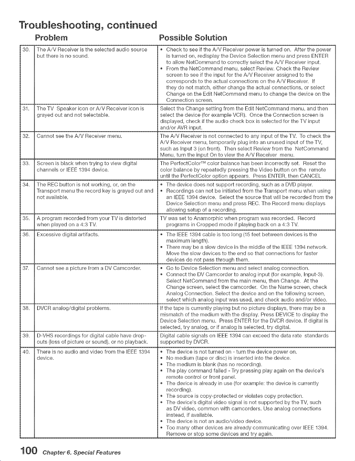
Troubleshooting, continued
PossibJe SoJution
30.
31.
The A/V Receiver is the selected audio source
but there is no sound.
The TV Speaker icon or A/V Receiver icon is
grayed out and not selectable.
32. Cannot see the A/V Receiver menu.
33.
34.
Screen is black when trying to view digital
channels or IEEE 1394 device.
The REC button is not working, or, on the
Transport menu the record key is grayed out and
not available.
35. A program recorded from your TV is distorted
when played on a 4:3 TV.
36. Excessive digital artifacts.
37. Cannot see a picture from a DV Camcorder.
38. DVCR analog/digital problems.
39.
40.
D-VHS recordings for digital cable have drop-
outs (loss of picture or sound), or no playback.
There is no audio and video from the IEEE 1394 ®
device, o
e
e
e
e
e
e
e
® Check to see if the A/V Receiver power is turned on. After the power
is turned on, redisplay the Device Selection menu and press ENTER
to allow NetCommand to correctly select the A/V Receiver input.
® From the NetCommand menu, select Review. Check the Review
screen to see if the input for the A/V Receiver assigned to the
corresponds to the actual connections on the A/V Receiver. if
they do not match, either change the actua! connections, or select
Change on the Edit NetCommand menu to change the device on the
Connection screen.
Select the Change setting from the Edit NetCommand menu, and then
select the device (for example VCR). Once the Connection screen is
displayed, check if the audio check box is selected for the TV input
and/or AVR input.
The A/V Receiver is not connected to any input of the TV. To check the
A/V Receiver menu, temporarily plug into an unused input of the TV,
such as input 3 (on front). Then select Review from the NetCommand
Menu, turn the input On to view the A/V Receiver menu.
The PerfectColor TM color balance has been incorrectly set. Reset the
color balance by repeatedly pressing the Video button on the remote
until the PerfectColor option appears. Press ENTER, then CANCEL
® The device does not support recording, such as a DVD player.
® Recordings can not be initiated from the Transport menu when using
an IEEE 1394 device. Select the source that will be recorded from the
Device Selection menu and press REC. The Record menu displays
allowing setup of a recording.
TV was set to Anamorphic when program was recorded. Record
programs in Cropped mode if playing back on a 4:3 TV.
® The IEEE 1394 cable is too long (15 feet between devices is the
maximum length).
® There may be a stow device in the middle of the IEEE 1394 network.
Move the slow devices to the end so that connections for faster
devices do not pass through them.
® Go to Device Selection menu and select analog connection.
Connect the DV Camcorder to analog input (for example, Input-3).
Select NetCommand from the main menu, then Change. At the
Change screen, select the camcorder. On the Name screen, check
Analog Connection. Select the device and on the following screen,
select which analog input was used, and check audio and/or video.
if the tape is currently playing but no picture displays, there may be a
mismatch of the medium with the display. Press DEVICE to display the
Device Selection menu. Press ENTER for the DVCR device, if digital is
selected, try analog, or if analog is selected, try digital.
Digital cable signals on IEEE 1394 can exceed the data rate standards
supported by DVCR.
The device is not turned on - turn the device power on.
No medium (tape or disc) is inserted into the device.
The medium is blank (has no recording).
The play command failed - Try pressing play again on the device's
remote control or front panel.
The device is already in use (for example: the device is currently
recording).
The source is copy-protected or violates copy protection.
The device's digital video signa! is not supported by the TV, such
as DV video, common with camcorders. Use analog connections
instead, if available.
The device is not an audio/video device.
Too many other devices are already communicating over IEEE 1394.
Remove or stop some devices and try again.
1 O0 Chapter 6. Special Features
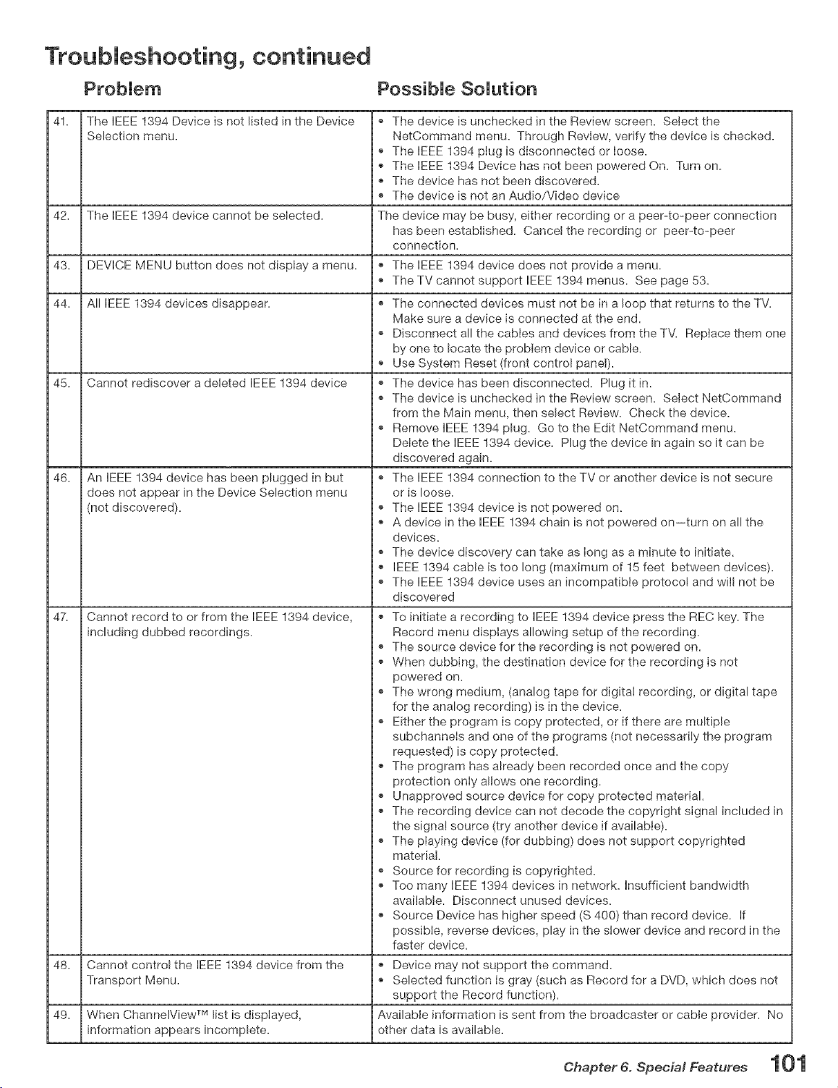
Troubleshooting, continued
PossibJe SoJution
41. The IEEE 1394 Device is not listed in the Device
Selection menu.
42. The EEE 1394 device cannot be seJected.
43. DEVICE MENU button does not display a menu.
44. All IEEE 1394 devices disappear.
45. Cannot rediscover a deleted EEE 1394 device
46.
47.
An IEEE 1394 device has been plugged in but
does not appear in the Device Selection menu
(not discovered). ®
The device is unchecked in the Review screen. Select the
NetCommand menu. Through Review, verify the device is checked.
® The IEEE 1394 plug is disconnected or Ioose.
The EEE 1394 Device has not been powered On. Turn on.
® The device has not been discovered.
® The device is not an Audio/Video device
The device may be busy, either recording or a peer-to-peer connection
has been established. Cancel the recording or peer-to-peer
connection.
® The EEE 1394 device does not provide a menu.
The TV cannot support EEE 1394 menus. See page 53.
® The connected devices must not be in a loop that returns to the TV.
Make sure a device is connected at the end.
® Disconnect all the cables and devices from the TV. Replace them one
by one to locate the problem device or cable.
Use System Reset (front control panel).
® The device has been disconnected. Plug it in.
The device is unchecked in the Review screen. SeJect NetCommand
from the Main menu, then select Review. Check the device.
® Remove IEEE 1394 plug. Go to the Edit NetCommand menu.
Delete the EEE 1394 device. Plug the device in again so it can be
discovered again.
The IEEE 1394 connection to the TV or another device is not secure
or is loose.
The EEE 1394 device is not powered on.
A device in the EEE 1394 chain is not powered on--turn on all the
devices.
The device discovery can take as long as a minute to initiate.
® EEE 1394 cable is too long (maximum of 15 feet between devices).
® The IEEE !394 device uses an incompatible protocol and will not be
discovered
® To initiate a recording to IEEE 1394 device press the REC key. The
Record menu displays allowing setup of the recording.
® The source device for the recording is not powered on.
When dubbing, the destination device for the recording is not
powered on.
® The wrong medium, (analog tape for digital recording, or digital tape
for the analog recording) is in the device.
® Either the program is copy protected, or if there are multiple
subchannels and one of the programs (not necessarily the program
requested) is copy protected.
® The program has already been recorded once and the copy
protection only allows one recording.
® Unapproved source device for copy protected material.
® The recording device can not decode the copyright signal included in
the signa! source (try another device if available).
® The playing device (for dubbing) does not support copyrighted
material.
. Source for recording is copyrighted.
® Too many IEEE 1394 devices in network. Insufficient bandwidth
available. Disconnect unused devices.
® Source Device has higher speed (S 400) than record device. If
possible, reverse devices, play in the slower device and record in the
faster device.
® Device may not support the command.
Selected function is gray (such as Record for a DVD, which does not
support the Record function).
Available information is sent from the broadcaster or cable provider. No
other data is available.
Cannot record to or from the EEE 1394 device,
including dubbed recordings.
48. Cannot control the EEE 1394 device from the
Transport Menu.
49. When ChannelView TM list is displayed,
information appears incomplete.
Chapter 6. Special Features
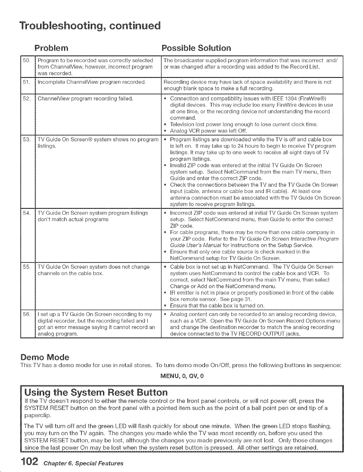
Troubleshooting, continued
PossibJe SoJution
50. Program to be recorded was correctJy selected The broadcaster supplied program information that was incorrect and/
from ChannelView, however, incorrect program or was changed after a recording was added to the Record List.
was recorded.
51. incomplete ChanneJView program recorded. Recording device may have lack of space availabiJity and there is not
enough blank space to make a full recording.
52. ChannelView program recording failed. _ Connection and compatibility issues with IEEE 1394 (FireWire@)
53.
54.
55.
56.
TV Guide On Screen@ system shows no program
listings.
TV Guide On Screen system program listings
don't match actual programs
TV Guide On Screen system does not change
channels on the cable box.
I set up a TV Guide On Screen recording to my
digital recorder, but the recording faiJed and I
got an error message saying it cannot record an
analog program.
digital devices. This may inciude too many FireWire devices in use
at one time, or the recording device not understanding the record
command.
Television lost power long enough to lose current ciock time.
, _ Analog VCR power was left Off.
Program IistJngs are downloaded while the TV is off and cable box
is left on. it may take up to 24 hours to begin to receive TV program
listings, it may take up to one week to receive aJleight days of TV
program listings.
Invalid ZiP code was entered at the initial TV Guide On Screen
system setup. Select NetCommand from the main TV menu, then
Guide and enter the correct ZiP code.
Check the connections between the TV and the TV Guide On Screen
input (cable, antenna or cable box and IR cable). At least one
antenna connection must be associated with the TV Guide On Screen
system to receive program listings.
incorrect ZiP code was entered at initial TV Guide On Screen system
setup. Select NetCommand menu, then Guide to enter the correct
ZiP code.
, _ For cable programs, there may be more than one cable company in
your ZiP code. Refer to the TV Guide On Screen Interactive Program
Guide User's Manual for instructions on the Setup Service.
Ensure that only one cable source is check marked in the
NetCommand setup for TV Guide On Screen.
Cable box is not set up in NetCommand. The TV Guide On Screen
system uses NetCommand to control the cable box and VCR. To
correct, seIect NetCommand from the main TV menu, then select
Change or Add on the NetCommand menu.
IR emitter is not in place or properly positioned in front of the cable
box remote sensor. See page 31.
Ensure that the cable box is turned on.
Analog content can only be recorded to an analog recording device,
such as a VCR. Open the TV Guide On Screen Record Options menu
and change the destination recorder to match the analog recording
device connected to the TV RECORD OUTPUT jacks.
Oemo Mode
This TV has a demo mode for use in retail stores. To turn demo mode On/Off, press the following buttons in sequence:
MENU, O, QV, 0
Using the System Reset Button
If the TV doesn't respond to either the remote control or the front panel controls, or will not power off, press the
SYSTEM RESET button on the front panel with a pointed item such as the point of a ball point pen or end tip of a
paperclip.
The TV wiii turn off and the green LED wiii flash quickly for about one minute. When the green LED stops flashing,
you may turn on the TV again. The changes you made while the TV was most recently on, before you used the
SYSTEM RESET button, may be lost, although the changes you made previously are not IosL Only those changes
since the last power On may be lost when the system reset button is pressed. All other settings are retained.
102 Chapter 6. Special Features
Trademark and License Information
LICENSOR'S SUPPLIERS DO NOT MAKE OR PASS ON TO END USER OR ANY OTHER THIRD PARTY, ANY EXPRESS,
IMPLIED OR STATUTORY WARRANTY OR REPRESENTATION ON BEHALF OF SUCH SUPPLIERS, INCLUDING, BUT
NOT MMiTED TO THE [MPMED WARRANTES OF NONqNFRiNGEMENT, TITLE, MERCHANTABiMTY OR HTNESS
FOR A PARTICULAR PURPOSE.
CabieCARD TM is a trademark of Cable Television Laboratories, Inc.
DCRTM Certification Logo is a trademark of the Consumer Electronics Association.
Manufactured under license from Doiby Laboratories. Doiby@ and the doubie-D symbol are registered trademarks of
Doiby Laboratories.
DTVMNK TM Certification Logo is a trademark of the Consumer Electronics Association.
FireWire@ is a trademark of Apple Computer, Inc. registered in the U.S. and other countries.
HDMff Mthe HDM[ logo and High-Definition Multimedia Interface are trademarks or registered trademarks of HDM[
Licensing LLC.
Lifestyle@ 28 is a trademark of the Bose Corporation.
This product incorporates copyright protection technology that is protected by U.S. patents and other intellectual
property rights. Use of this copyright protection technology must be authorized by Macrovision, and is intended for
home and other limited pay-per-view uses only unless otherwise authorized by Macrovision. Reverse engineering or
The PaneiLink Cinema Partners logo and the "PaneiLink Cinema," "PLC" and "PLC Content Ready" word
mmm
P LC marks are trademarks of Silicon Image, Inc. and are used under a license from Silicon Image, [nc or
PaneiLink Cinema, LLC.
Piaystation@ 2 is a trademark of the Sony Corporation.
In the United States, TV GUIDE and other related marks are registered marks of Gemstar-TV Guide International, Inc.
and/or one of its affiliates.
The TV Guide On Screen@ system is manufactured under license from Gemstar-TV Guide International, Inc. and/or one
of its affiliates.
The TV Guide On Screen@ system is protected by one or more of the following issued United States patents:
6,498,895; 6,418,556; 6,331,877; 6,239,794; 6,154,203; 5,940,073; 4,908,713; 4,751,578; 4,706,121.
XSox TM iSa trademark of the Microsoft Corporation.
NetCommand@, ViewPoint@, QuickView TM, SuperQuickView TM, Diamond Shield TM, PerfectCoior TM and SharpEdge TM
are trademarks of Mitsubishi Digital Electronics America, Inc.
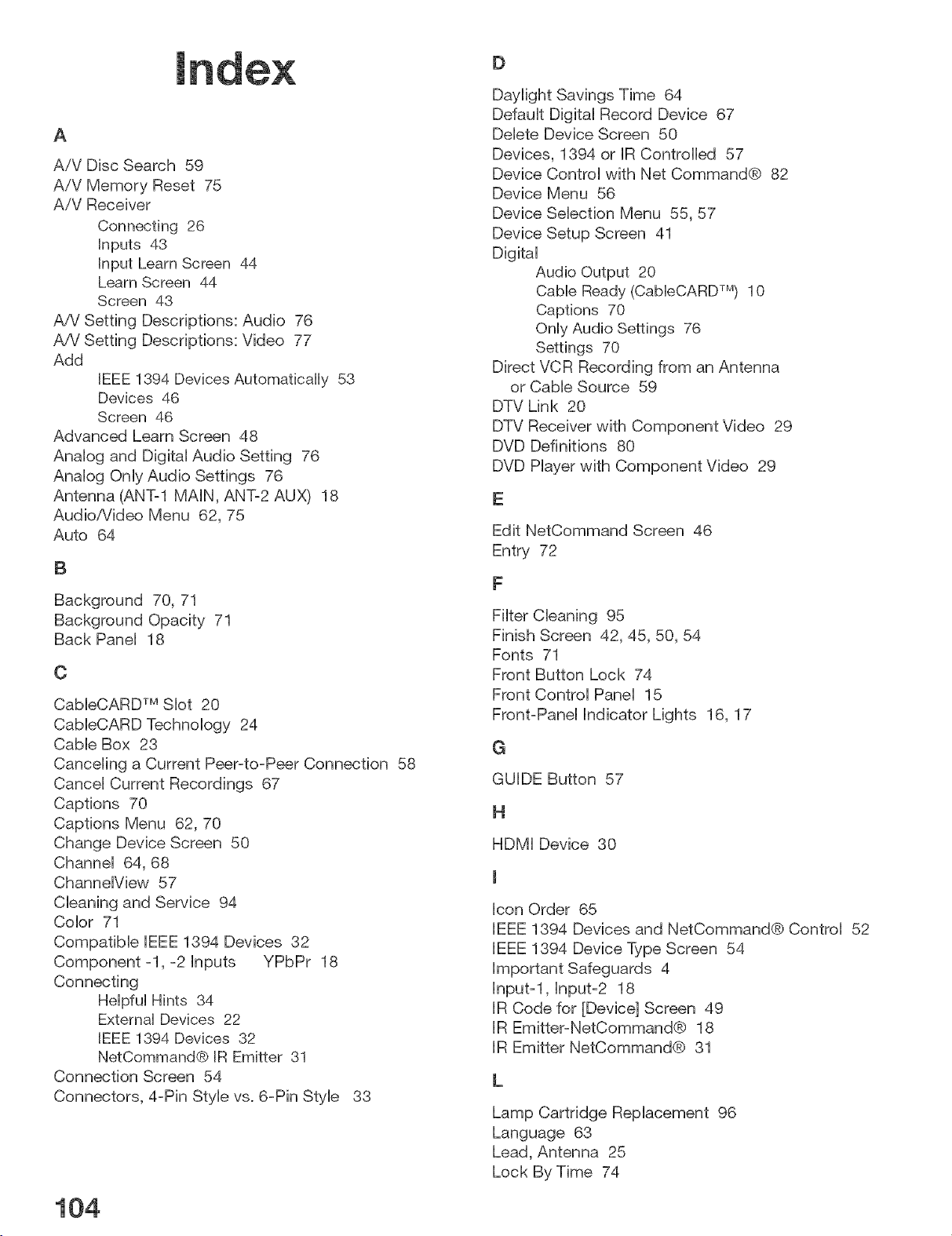
A
A/V Disc Search 59
A/V Memory Reset 75
A!V Receiver
Connecting 26
inputs 43
input Learn Screen 44
Learn Screen 44
Screen 43
A/V Setting Descriptions: Audio 76
A/V Setting Descriptions: Video 77
Add
IEEE 1394 Devices Automatbally 53
Devices 46
Screen 46
Advanced Learn Screen 48
Analog and DigkaI Audio Setting 76
Analog Only Audio Settings 76
Antenna (ANT-1 MAIN, ANT-2 AUX) 18
Audio/Video Menu 62, 75
Auto 64
B
Background 70, 71
Background Opacity 71
Back Panel 18
¢
CableCARD TM Slot 20
CableCARD Technology 24
Cable Box 23
Canceling a Current Peer-to-Peer Connection 58
Cancel Current Recordings 67
Captions 70
Captions Menu 62, 70
Change Device Screen 50
Channel 64, 68
ChanneIView 57
Cleaning and Service 94
Color 71
Compatible IEEE 1394 Devices 32
Component -1, -2 inputs YPbPr 18
Connecting
Helpful Hints 34
External Devices 22
IEEE 1394 Devices 32
NetCommand@ IR Emitter 31
Connection Screen 54
Connectors, 4-Pin Style vs. 6-Pin Style 33
104
D
Daylight Savings Time 64
Default Digital Record Device 67
Delete Device Screen 50
Devices, 1394 or IR Controlled 57
Device Control with Net Command@ 82
Device Menu 56
Device Selection Menu 55, 57
Device Setup Screen 41
Digital
Audio Output 20
Cable Ready (CabieCARD TM) 10
Captions 70
Only Audio Settings 76
Settings 70
Direct VCR Recording from an Antenna
or Cable Source 59
DTV Link 20
DTV Receiver with Component Video 29
DVD Definitions 80
DVD Player with Component Video 29
Edit NetCommand Screen 46
Entry 72
F
Filter Cleaning 95
Finish Screen 42, 45, 50, 54
Fonts 71
Front Button Lock 74
Front Control Panel 15
Front-Panel indicator Lights 16, 17
G
GUIDE Button 57
H
HDMI Device 30
icon Order 65
IEEE 1394 Devices and NetCommand@ Control 52
iEEE 1394 Device Type Screen 54
important Safeguards 4
Input-l, Input-2 18
iR Code for [Device] Screen 49
IR Emitter-NetCommand@ 18
IR Emitter NetCommand@ 31
Lamp Cartridge Replacement 96
Language 63
Lead, Antenna 25
Lock By Time 74
M
Memorize 63
Memory 68
N
Name, Channel Menu 68
Name for 1394 Device Screen 53
Name Screen 45, 48
NetCommand@
Home Network Control System 10
Initial Setup 40
Setup 22
Setup On-Screen Buttons 88
Specialized Device Keys 93
information Screen 40
Menu 64, 67
New 1394 Device Screen 55
0
On-Screen information Displays 92
Opacity, Font 71
Operation of PiP and POP 78
Pass code, ',/-Chip 72
Peer-to-Peer Connection 58
PiP Device Selection Menu 55
PIR Operation of 78
POR Operation of 78
Prefer Digital 68
Programming the Remote to Control NetOommand A/V
Products 89
Programming the Remote to Control Other Brands of
Audio and Video Products 89
R
Recording Now 66
Record List 67
Record Menu 66
Recording Combinations 98
Remote Control
Remote Control Buttons 13
Remote Control Functions 12
Remote Control Programming Codes 90
Remote Control with NetCommand@ 37
Review Screen, NetCommand@ 42
RF Connection for Cable Screen 49
S
S-Video 26
Satellite Receiver 28
Separate UHF and VHF Leads, Antennas with 25
Settings
Video 77
Setting up a Peer-to-Peer Connection 58
Setup Menu 62, 63
Set Date 63
Set Day 64
Set Time 64
Size 71
Special Features 10
Specifications 87
SQV (SuperQuickView TM) 69
Stereo System (AA/Receiver) 28
System Reset Button 104
Time-Delayed Recording 66
Timer On/Off 64
Time Zone 64
Three-Dimensional (3D) Graphical Menu System 39
Track List Screen 59
Trademark and License information 105
Transport Menu 65
Troubleshooting 100
TV Accessories 11
TV Guide On Screen@ 12, 41, 67
TV Speakers 75
V
V-Chip
Definitions 73
Exceptions 73
Lock, Bypassing the V-Chip 85
Lock Menu 78
Pass code 72
Video Settings 77
Viewing Combinations 98
W
Wall Outlet Cable 23
Warranty 109
Welcome Screen 40
Widescreen Picture Format (16:9) 10
MITSUBISHI TV SOFTWARE
END-USER LICENSE AGREEMENT FOR EMBEDDED SOFTWARE
IMPORTANT = READ CAREFULLY: This License Agreement is a legal agreement between you (either an individual or an entity) and
Mitsubishi Digital Electronics America, Inc. (MDEA) for all software pre installed and/or provided along with this television ("Software").
By utilizing this television and Software, you agree to be bound by the terms of this License Agreement.
The Software is protected by United States copyright laws and international treaty provisions, as well as other intellectual property
laws and treaties. The Software is licensed, not sold.
1. UCENSE GRANT. MDEA grants you a non-exclusive, non-transferable, limited right and license to use one copy of the
Software only with the Mitsubishi television model that included this owner's guide and owned by you.
2= RmGHTS AND UMBTATmONS.
Software Not for Resale. You may not resell or otherwise transfer for value the Software, except in coniunction with a sale of the TV
that Software has been pre installed.
Prohibition on Reverse En_q, Decompilation and Disassembl'& The Software contains trade secrets or other proprietary
material in its human perceivable form and to protect them, you may not reverse engineer, decompfie, or disassemble, or otherwise
reduce the Software to any human perceivable form, except to the extent that the foregoing restriction is expressly prohibited by
applicable law.
Separation of Components. The Software is licensed as a single product. Its component parts may not be separated for use on more
than one TM
No Rental. You may not rent, lease, lend, or sublicense the Software.
Trademarks. This License Agreement does not grant you any rights to any trademarks of MDEA.
3. WOLATmONS. You understand that any use, copying or transfer of the Software, except as permitted pursuant to this License,
may subject you to serious criminal and civil penalties including damages and an award to MDEA of attorneys' fees in connection with
any violation of this License. You further understand that you may be held lega!ly responsible for any copyright infringement or other
violation of intellectual property rights that is caused, encouraged, or induced by your failure to abide by the terms of the License.
This license is effective until terminated, and will terminate immediately without notice from MDEA or judicial resolution if you fail to
comply with any provision of this License.
4. COPYRIGHT. All title and intellectual property rights in and to the Software (including but not limited to any images,
photographs, animations, video, audio, music, text, and "applets" incorporated into the Software), and any accompanying printed
materials are owned by or licensed to MDEA. All title and intellectual property rights in and to the content which may be accessed
through use of the Software is the property of the respective content owner and may be protected by applicable copyright or other
intellectual property laws and treaties. This License Agreement grants you no rights to use such content, except that you own the
media on which the Software is recorded, but MDEA and its licensors retain ownership of the Software itself. All rights not expressly
granted are reserved by MDEA.
5. EXPORT RESTRmCTmONS. MDEA is licensing the Software for use within the United States. You agree that you will not export
or re-export the Software. You specifically agree not to export or re-export the Software: (i) to any country to which the U.S. has
embargoed or restricted the export of goods or services, which currently include, but are not necessarily limited to Cuba, Iran, Iraq,
Libya, North Korea, Sudan, and Syria, or to any national of any such country, wherever located, who intends to transmit or transport
the Software back to such country; (ii) to any person or entity who you know or have reason to know will utilize the Software in
the design, development, or production of nuclear, chemical, or biological weapons; or (iii) to any person or entity who has been
prohibited from participating in U.S. export transactions by any federal agency of the U.S. government. You warrant and represent
that neither the BXA nor any other U.S. federal agency has suspended, revoked, or denied your export privileges.
6. DmSCLAmMER OF WARRANTY. EXCEPT AS OTHERWmSE PROWDED IN THIS UCENSE OR IN THE LIMBTED
WARRANTY APPLICABLE TO THE TV, MDEA MAKES NO OTHER WARRANTmES OF ANY KIND WHATSOEVER REGARDmNG
THE SOFTWARE AND HEREBY EXPRESSLY DISCLAIMS ALL WARRANTIES OF ANY K_ND WHATSOEVER, EXPRESS OR
mMPLtED, WroTH RESPECT TO THE SOFTWARE. ALL mMPUED WARRANTmES, INCLUDING, WBTROUT L}MITATION, THE
mMPL_ED WARRANTmES OF MERCRANTABIUTY AND FITNESS FOR A PARTICULAR PURPOSE ARE HEREBY EXPRESSLY
DISCLAIMED BY MDEA. mNNO EVENT SHALL MDEA BE UABLE TO YOU OR ANY THIRD PARTBES, IN CONTRACT, IN TORT
OR OTHERWISE, FOR ANY DmRECT, INDmRECT, SPECIAL, BNCtDENTAL OR CONSEQUENTIAL DAMAGES OF ANY KIND OR
NATURE. BECAUSE SOME JURmSDICTmONS DO NOT ALLOW THE EXCLUSION OR LIMITATION OF IMPLIED WARRANTmES,
THE ABOVE LIMBTATmON MAY NOT APPLY TO YOU.
7. LIMmTATION OF LmABIL_TY, MDEA SHALL NOT, UNDER ANY C_RCUMSTANCES BE UABLE TO YOU OR ANY THIRD
PARTtES FOR ANY DAMAGES OF ANY NATURE, WHETHER _ND_RECT, SPECIAL, _NC}DENTAL, CONSEQUENTIAL
OR OTHERWISE, _NCLUD_NG, BUT NOT L_MITED TO, ANY CLAIMS FOR LOST PROFITS, LOSS OF GOOD W_LL OR
EXPENDITURES MADE OR COMMITTED FOR _N REUANCE ON THE CONTiNUATiON OF TRtS UCENSE. YOU AGREE
THAT NEITHER MDEA'S BREACH OF THS UCENSE NOR tTS FAILURE TO REPAIR A DEFECT, ERROR OR BUG SHALL
CONSTITUTE A FAILURE OF THE ESSENTIAL PURPOSE OF THIS L_CENSE. BECAUSE SOME JURiSDiCTiONS DO NOT
ALLOW THE EXCLBStON OR UM_TAT_ON OF UAB_UTY FOR CONSEQUENTIAL OR tNC_DENTAL DAMAGES, THE ABOVE
L_M_TAT_ONS MAY NOT APPLY TO YOU. MDEA's HabiHty to you for direct damages for any cause whatsoever and regardless
of the form of the action, will be Hmited to the money paid by you for the TV (based on fair market va_ue of the TV) that
caused the damages,
8. GENERAL. This License Agreement will be governed by the laws of the State of California.
106

Mitsubishi LCD Rear Projection Television Limited Warranty
M(TSUBISHI DIGmTAL ELECTRONICS AMERICA, (NC. ("MDEA") warrants as follows to the or(g(na( purchaser of th(s te(ev(s(on from an
authorized MITSUBISBI Audio/Video Dealer, should it prove defective by reason of against defects arising from improper workmanship
and/or material:
a. Parts. The lenticular (i.e. front picture) screen is warranted against defects in materials and workmanship for a period of thirty (30) days from the
date of the original purchase at retail. The lamp and all other parts (except any software incorporated into this television) are warranted for a period
of one (1) year from the date of the original purchase at retail. We will repair or replace, at our option, any defective part without charge for the part.
Parts used for replacement may be replaced with those of like kind and quality and may be new or remanufactured. Parts used for replacement are
warranted for the remainder of the original warranty period.
b. Embedded Software. MDEA warrants that all software incorporated into this television set (the "Embedded Software") will perform in accordance
with the functional description of Embedded Software in all material respects, but MDEA does not warrant that the Embedded Software is error-free.
MDEA also does not warrant that the Embedded Software will be compatible under IEEE 1394 AV/C and HAVi software standards with products
produced by any other manufacturer. The limited warranty contained in this section shall continue for a period of one (1) year from the date of the
original purchase at retail. If, after prompt notice within the warranty period, MDEA determines that the Embedded Software has failed to perform in
accordance with such functional description in all material respects and if such failure is not due to accident, misuse, modification or misapplication
of the Embedded Software, then MDEA shall modify or replace the nonconforming Embedded Software at no charge to you, which at MDEA's sole
discretion may be fulfilled by means of modification or replacement software contained on a replacement memory card for Customer installation.
The foregoing shall be MDEA's sole obligation to you under this limited warranty. All rights under this limited warranty on the Embedded Software are
also subject to your acceptance of and compliance with the terms of the Software License Agreement applicable to this television, and this limited
warranty on the Embedded Software shall be null and void if the Embedded Software is modified or changed in any manner except as specifically
authorized by MDEA.
c. Labor. For thirty (30) days after the original purchase at retail, we will repair or replace, at our option, the lenticular screen if it proves defective.
For certain items that are designed to be replaced by the consumer, including (but not limited to) some Embedded Software, the consumer is solely
responsible for any replacement labor. Air filter cleaning is normal consumer required maintenance and labor for this procedure is not covered under
warranty. Please refer to the Owner's Guide for air filter cleaning procedures. For all other parts, we will provide the labor for a warranty repair by an
authorized MITSUBISHI service center without charge for one (1) year from the original date of purchase at retail.
d. Notice. To obtain warranty service, you must notify an authorized MITSUBISHI service center of any defect within the applicable warranty time
period.
e. This LCD Projection Television uses three LCD panels to create the screen image. This technology creates the image using small dots, or picture
elements (pixels). Your LCD Projection TV is manufactured to a high level of performance and quality, in fact, 99.99% perfect in the number of
properly functioning pixels. As in other display technology, sometimes a pixel is continuously active, inactive or the incorrect color. Our standard is
clear; MDEA warrants only that the percentage of properly functioning pixels will be not less than 99.99% of all pixels.
BEFORE REQUESTING SERVICE, please review the instruction bookmet to insure proper installation and correct customer control
adjustment. If the problem persists pRease arrange for warranty service.
1. TO OBTAIN WARRANTY SERVICE:
a. Contact your nearest authorized MITSUBISHI service center, whose name and address can be obtained from your MITSUBISHI dealer, by writing
at the address provided below, calling MDEA at the 800-332-2119, or by using the support feature of our website site at www.Mitsubishi-tv.com.
b. Warranty service will be provided in your home or, if required, at an authorized service shop, provided that your television is located within the
geographic territory customarily covered by an authorized MITSUBISHI service center. If not, you must either deliver your television to an authorized
service location at your own expense, or pay for any travel and/or transportation costs the service center may charge to and from your home. Actual
service labor will be provided without charge.
c. Proof of purchase date from an authorized MITSUBISHI dealer is required when requesting warranty service. Present your sales receipt or other
document which establishes proof and date of purchase. THE RETURN OF THE OWNER REGISTRATION CARD IS NOT A CONDITION OF COVERAGE
UNDER THIS LIMITED WARRANTY. However, please return the Owner Registration Card so that we can contact you should a question of safety arise
which could affect you.
d. To obtain a replacement lamp during the warranty period, please contact the MDEA Consumer Relations Department at (800) 332=2119.
After the warranty period you may order the lamp direcBy from the MDEA Parts Department at (800) 553=7278.
2. THIS LIMITED WARRANTY DOES NOT COVER:
a. Up to .01% pixel outages (small dot picture elements that are dark or incorrectly illuminated).
b. Damage to the lenticular screen or Fresnel lens, screen frame, cosmetic damage or to any other damage where such damage is caused by
unauthorized modification, alteration, repairs to or service of the product by anyone other than an authorized MITSUBISHI service center; physical
abuse to or misuse of the product (including any failure to carry out any maintenance as described in the Owner's Guide including air filter cleaning or
any product damaged by excessive physical or electrical stress); any products that have had a serial number or any part thereof altered, defaced or
removed; product use in any manner contrary to the Owner's Guide; freight damage; or any damage caused by acts of God or other factors beyond
the reasonable control of MDEA, such as power surge damage caused by electrical system or lightning.
(Continued on next page)

Mitsubishi LCD Rear Projection Temevision Limited Warranty (continued)
This limited warranty also excludes service calls where no defect in the product covered under this warranty is found, service calls related to
unsatisfactory audio or visual reception or signal unless caused by a defect in the product that is covered under this limited warranty, all costs,
expenses or any other damages arising from product installation, or set-ups, any adjustments of user controls (including contrast, brightness, color,
tint, fine tuning, sharpness), other adjustment necessary to prepare the unit for display or use, connection with any external audio receiver, antenna,
cable or satellite systems, or service of products purchased or serviced outside the U.S.A. Please consult the operating instructions contained in the
Owner's Guide furnished with the product for information regarding user controls.
3. ANY EXPRESS WARRANTY NOT PROVIDED HEREIN, AND ANY REMEDY WHICH, BUT FOR THIS PROVISION, MIGHT ARISE BY IMPLICATION
OR OPERATION OF LAW, IS HEREBY EXCLUDED AND DISCLAIMED. THE IMPLIED WARRANTIES OF MERCHANTABILITY AND OF FITNESS FOR
ANY PARTICULAR PURPOSE ARE EXPRESSLY LIMITED TO A TERM OF ONE YEAR.
4. UNDER NO CIRCUMSTANCES SHALL MDEA BE LIABLE TO PURCHASER OR ANY OTHER PERSON FOR ANY INCIDENTAL, SPECIAL OR
CONSEQUENTIAL DAMAGES, WHETHER ARISING OUT OF BREACH OF WARRANTY, BREACH OF CONTRACT, OR OTHERWISE.
5. Some states do not allow limitations on how long an implied warranty lasts, or the exclusion or limitation of incidental, special, or consequential
damages, so the above limitations or exclusions may not apply to you.
6. This limited warranty gives you specific legal rights, and you may also have other rights which vary from state to state.
MITSUBISHI DtGmTAL ELECTRONICS AMERmCA, INC.
9351 Jerorfimo Road
Irvine, CA 92618-1904
108

_ mTSUBmSHm
ELECTRIC
DIGITAL TELEVIBIDNB _
Website:
www.mitsubishi-tv.com
To order repMacement or
additionaU remote controUs,
Mamp cartridges or Owner's
Guides, call
For questions, call Consumer
ReMations at
© 2005 Mitsubishi Digital Electronics America, Inc. Written and Printed in the U.S.A.
853B541A10