Loading ...
Loading ...
Loading ...
6. Measure the vent piping and cut to required
lengths• Pipes must be cut at right angles and
deburred to ensure a good smooth fit with
sufficient overlap for the glue joints• Correct any
interference conditions•
7. Provide support hangers for horizontal vent
piping every 4 ft. (1.2m) to prevent sagging
and stress• Provide a minimum of 1/8" (3mm)
rise per 4 ft. (1.2m) of vent piping to ensure
adequate drainage (polypropylene vent systems
require a 1/4 in. (6mm) rise per 1 ft. (0.3m)
of vent pipe)• Horizontal vent piping must not
sag to form valleys where condensate can
collect• Vertical venting shall be supported
every 5 ft. (1.5m). Use appropriate support
straps and vibration isolators (foam pads) on
straight sections only. Allow sufficient clearance
for expansion and contraction of the venting
system•
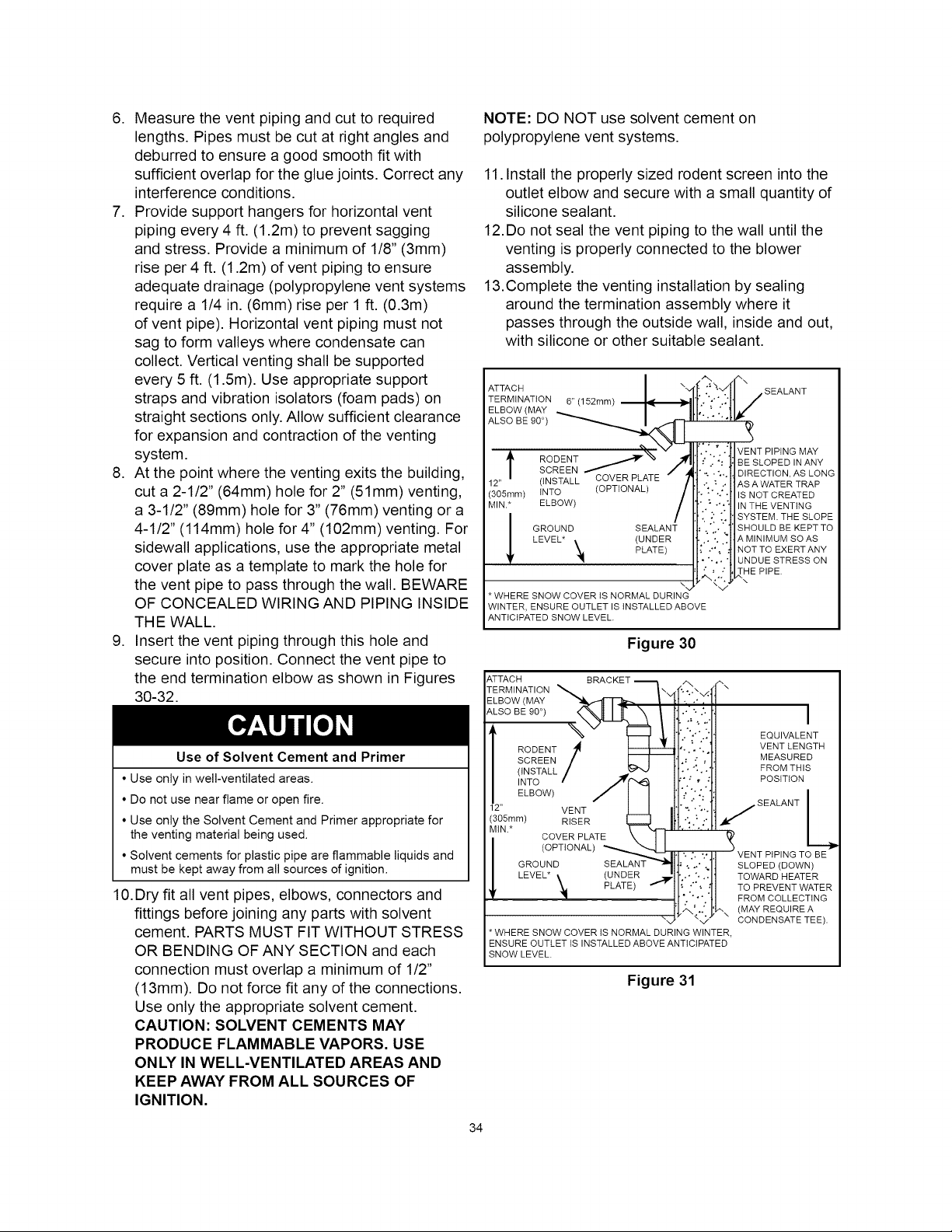
8. At the point where the venting exits the building,
cut a 2-1/2" (64mm) hole for 2" (51mm) venting,
a 3-1/2" (89mm) hole for 3" (76mm) venting or a
4-1/2" (114mm) hole for 4" (102mm) venting• For
sidewall applications, use the appropriate metal
cover plate as a template to mark the hole for
the vent pipe to pass through the wall. BEWARE
OF CONCEALED WIRING AND PIPING INSIDE
THE WALL.
9. Insert the vent piping through this hole and
secure into position• Connect the vent pipe to
the end termination elbow as shown in Figures
30-32•
Use of Solvent Cement and Primer
• Use only in well-ventilated areas.
• Do not use near flame or open fire.
• Use only the Solvent Cement and Primer appropriate for
the venting material being used.
• Solvent cements for plastic pipe are flammable liquids and
must be kept away from all sources of ignition.
10. Dry fit all vent pipes, elbows, connectors and
fittings before joining any parts with solvent
cement• PARTS MUST FIT WITHOUT STRESS
OR BENDING OF ANY SECTION and each
connection must overlap a minimum of 1/2"
(13mm). Do not force fit any of the connections•
Use only the appropriate solvent cement•
CAUTION: SOLVENT CEMENTS MAY
PRODUCE FLAMMABLE VAPORS. USE
ONLY IN WELL-VENTILATED AREAS AND
KEEP AWAY FROM ALL SOURCES OF
IGNITION.
NOTE: DO NOT use solvent cement on
polypropylene vent systems•
11. Install the properly sized rodent screen into the
outlet elbow and secure with a small quantity of
silicone sealant.
12.Do not seal the vent piping to the wall until the
venting is properly connected to the blower
assembly.
13.Complete the venting installation by sealing
around the termination assembly where it
passes through the outside wall, inside and out,
with silicone or other suitable sealant.
ATTACH
TERMINATION
ELBOW (MAY
ALSO BE 90 °)
6" (152mm)
.SEALANT
t
12"
(305ram)
MIN.*
!
RODENT
SCREEN
(INSTALL COVER PLATE
tNTO (OPTIONAL)
ELBOW)
GROUND SEALANT
LEVEL* (UNDER
'_ PLATE)
\..
* WHERE SNOW COVER iS NORMAL DURING
VENT PIPING MAY
'."•i.• ':" BE SLOPED IN ANY
• "-..',,• DIRECTION, AS LONG
: ' AS A WATER TRAP
"":" ".;" 'IS NOT CREATED
IN THE VENTING
IiI iI!IS STEMT ESO
SHOULD BE KEPT TO
A MINIMUM SOAS
NOT TO EXERT ANY
i UNDUE STRESS ON
.,L.'.,." _HE PIPE.
\
WINTER, ENSURE OUTLET IS INSTALLED ABOVE
ANTICIPATED SNOW LEVEL.
Figure 30
ATTACH BRACKET ---k
TERMINATION _ _,._
ELBOW (MAY _ I
ALSOBE0O°
112 T°w)--
" VENT
(395mm)
MtN*
GROUND
LEVEL*
(UNDER
PLATE)
" ",'\x,<; ""
. _., EQUIVALENT
VENT LENGTH
MEASURED
• • "'.." FROM THIS
• : , : POSITION
""" "'" L
.:".:_,." SEALANT
") .'. 2"
VENT PIPING TO BE
SLOPED (DOWN)
TOWARD HEATER
TO PREVENT WATER
FROM COLLECTING
(MAY REQUIRE A
CONDENSATE TEE).
* WHERE SNOW COVER iS NORMAL DURING WINTER,
ENSURE OUTLET iS INSTALLED ABOVE ANTICIPATED
SNOW LEVEL.
Figure 31
34
Loading ...
Loading ...
Loading ...