Loading ...
Loading ...
PLANNING
GUIDE
All specications subject to change without notice. www.dacor.com Ph. 800.793.0093
• Seal openings in the wall behind the range and in the floor below.
• The grey area in the diagram below shows the suggested gas/
electrical utilities. Existing utilities may be used if they do not
hinder range placement.
• Gas/electrical utilities must be located so the range can be
moved for service without being disconnected.
• An external, manual shut-off valve must be installed between
the gas inlet and range so gas to the range can be shut on/off.
• Installation must allow access to the gas shut-off valve and
circuit-breaker panel/fuse box when the range is in place.
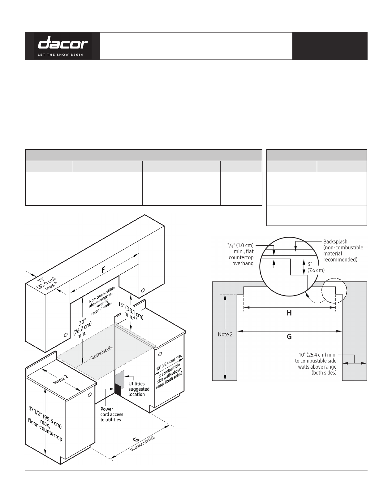
Cabinet Layout
• All maximum/minimum dimensions and clearances in the
diagrams below must be maintained for safe operation.
• Place the range away from drafts (open doors and windows, and
home heating/cooling systems).
• Do not install cabinets over the range, or to reduce risk of burn
injury from reaching over a hot cooktop, install a range hood that
projects horizontally at least 5” beyond the cabinet bottoms.
• The range may be installed against the rear wall. Dacor strongly
recommends installing a backguard or non-combustible
material on the rear wall between the range vent hood.
Heritage
®
30”, 36”, 48” Wide,
Dual-Fuel Ranges
Page 3 of 3
All tolerances: ±¹/₁₆” (±1.6 mm), unless otherwise stated.
HDPRS/HDERS
Standard Cutout with
Range Hood
1. Vertical from range grate level to combustible overhead surface; if install-
ing an overhead hood, see hood specications for minimum required
clearances.
2. Cabinet/countertop depth is at customer discretion, but cabinet face must
not protrude beyond rear of range front panel. (See Pg. 1 for dimensions.)
3. Consult local codes for exact location requirements.
4. Vertical from grate level to combustible surface.
5. Not applicable to cabinets that horizontally are over 10” (25.4 cm) from
range edge.
APPROVED DOWNDRAFT VENTS
Range Downdraft Vent
HDPRS/HDERS 30 MRV30-ER
HDPRS/HDERS 36 MRV36-ER
HDPRS/HDERS 48 MRV48-ER
IMPORTANT: See downdraft installation instruc-
tions for duct and electrical installation require-
ments. Use only approved Dacor downdraft vents.
CUTOUT DIMENSIONS
Model F: recommended/min. G: min./max. H
HDPRS/HDERS 30 36” (91.4 cm) / 30” (76.2 cm) 30” (76.2 cm) / 30 ” (76.5 cm) 27 " (69.5 cm)
HDPRS/HDERS 36 42” (106.7 cm) / 36” (91.4 cm) 36” (91.4 cm) / 36 ” (91.8 cm) 33 ” (84.8 cm)
HDPRS/HDERS 48 54” (137.2 cm) / 48” (122.0 cm) 48” (121.9 cm) / 48 ” (122.2 cm) 43 ” (110.5 cm)
Countertop Cutout For Downdraft Vent