Loading ...
Loading ...
Loading ...
–
4
–
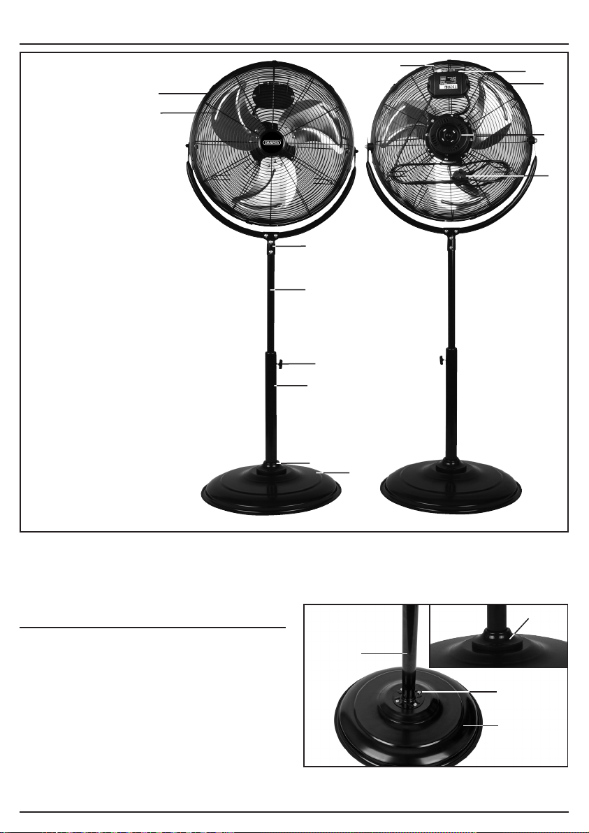
5. IDENTIFICATION – FIG.A
FIG.A
(1) Guard
(2) Blade
(3) Motor
(4) Switch
(5) Guard Clip
(6) Power Supply Cord
(7) Guard Handle
(8) “T” JOINT
(9) Inner Pole
(10) Height adjustment
(11) Outer Pole
(12) Base
(13) Decorative Cover
Note: For details of our full range of accessories and consumables, please visit drapertools.com
6. ASSEMBLY
6.1 ATTACH BASE – FIG. 1
Attach the base (12) to the outer pole (11) using the four
bolts (12.1), spring washers and nuts provided.
Then slide the decorative cover (13) over pole.
1
FIG.
(12)
(13)
(12.1)
(11)
Stock No. 70429 shown
(1)
(2)
(3)
(6)
(4)
(7)
(8)
(9)
(10)
(11)
(13)
(5)
(12)
Loading ...
Loading ...