Owners
Manual
FOR POTABLEWATER
HEATING ONLY
NOT SUITABLEFOR
SPACEHEATING.
FOR USE ONLY IN
MOBILE HOMES
Hodel No.
MODEL NUMBERS:
153.333832 30 Gal.
153.333932 40 Gal.
Caution:
Read and Follow
All Safety Rules and
Operating Instructions
Before First Use of
This Product.
Savethis Manual for Future Reference.
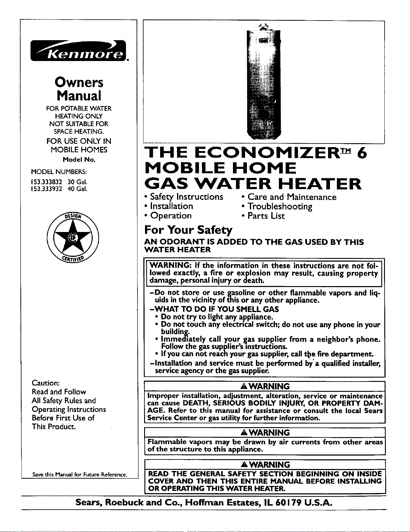
THE ECONOMIZER TM 6
MOBILE HOME
GAS WATER HEATER
• Safety Instructions
• Installation
• Operation
For Your Safety
• Care and Maintenance
• Troubleshooting
• Parts List
AN ODORANT IS ADDED TO THE GAS USED BY THIS
WATER HEATER
WARNING: If the information in these instructions are not fol-
lowed exactly, a .fire or explosion may result, causing property
damage, personal ,nlury or death.
-Do not store or use gasoline or other flammable vapors and liq-
uids in the vicinity of this or any other appliance.
-WHAT TO DO IF YOU SMELL GAS
: Do not try to light any appliance.
Do not touch any electrical switch; do not use any phone in your
building.
i Immediately call your gas suppl,er from a neighbor's phone.Follow the gas supplier'sinstructions.
If you can not reach your gas suppher, call the fire department.
-Installation and service must be performed by'a qua ifled installer,
service agency or the gas supplier.
_,WARNING . J
Improper installation, adjus_on, service or maintenance|
can cause DEATH, SERIOUS BOD!LY INJURY, OR PROPERTY DAM- i
AGE. Refer to this manual for assistance or consult the local Sears|
Service Center or gas utility for further information. |
_,WARNING
Flammable vapors may be drawn by air currents from other areas
of the structure to this appliance.
AWARNING
READ THE GENERAL SAFETY SECTION BEGINNING ON INSIDE
COVER AND THEN THIS ENTIRE MANUAL BEFORE INSTALLING
OR OPERATING THIS WATER HEATER.
Sears, Roebuck and Co., Hoffman Estates, IL 60179 U.S.A.
Safety Precautions
AWARNING ]
Improper installatio_lteration, service or [
maintenance can cause DEATH, SERIOUS BODILYI
INJUR_,OR PROPERTY DAMAGE. Referto this manualfor
assistanceor consult your local Sears Service Center forl
further information. J
AWARNING
WATER HEATERSEQUIPPED FOR ONE TYPE GAS ONLY:
Thiswaterbeaterisequippedfor onetype gasonly.Checkthe
modelrating platenearthe gascontrolvalvefurthe correctgas.
DO NOT USETHIS WATERHEATERWITH ANY GASOTHER
THAN THE ONE SHOWN ON THE MODEL RATING PLATE.
Failureto usethe correct gascan causeproblemswhich can
result in DEATH, SERIOUSBODILY INJURY,OR PROPERTY
DAMAGE.If youhaveanyquestionsor doubtsconsultyour gas
supplieror localutility.
AWARNING
INSTALLATIONSIN AREASWHERE FLAMMABLELIQUIDS
VAPORS) ARE LIKELY T_. BE PRESENT OR STORED
GARAGES, STORAGE, AND UTILITY AREAS, ETC):
Flammableliquids(suchas gasoline,solvents,propane(LP) or
butane, etc.), all of which emit flammable vapors,may be
improperlystoredor usedin suchareas.The gaswater heater
pilotlightor mainbumer canignitesuchvapors.The resulting
flashbackandErecancausedeathor seriousburnsto anyonein
thearea,aswall aspropertydamage.
If installationinsuchareasisyour onlyoption,then the installa-
tion must be accomplishedin a waythat the pilot game and
main bumerflameareelevatedfromthe floorat least 18inches.
While this mayreduce the changesof flammablevaporsfroma
floorspillbeingignited,gasolineand otherflammablesubstances
shouldneverbestored or usedin the sameroom or area con-
talninga gaswater heateror other openflameor sparkproduc-
ingappliance.
NOTE: Flammablevaporsmay be drawn by air currentsfrom
otherareasof the structuretothe appliance.
AWARNING
If this water heaterwill be usedin beautyshops,barbershops,
cleaningestablishments,or seif-servicelaundrieswith dry
cleaningequipment, it is imperativethat the water heater or
water heatersbe installedso that combustionand vantilation
air be taken from outsidetheseareas.Referto the "Facts to
ConsiderAbout the Location"sectionof this manual and also
the latestedition of the National FuelGasCode,ANSI Z223.1
also referred to as NFPA 54 fur specificsprovidedconcemin
air required.
AWARNING I
A Ere can start if combustiblematerials suchas clothing,I
cleaningmaterials,or flammable liquidsare placed against
or nextto the water heater.
AWARNING
At the time of manufacturethis water heater was provided
with a combinationtemperatere-pressuresrelief valvecertified
by a nationally recognized testing laboratory that maintains
_eriodicinspectionof productionof listedequipment or mate-
rials, as meeting the requirements for Relief Valves and
AutomaticGasShutoffDevicesfor Hot Water SupplySystems,
and the latest edition of ANSI Z21.22 and the coderequire-
mentsof ASME. If replaced,the valvemust meet the require-
ments oflocalcodes,but notlessthana combinationtempera-
ture andpressurereliefvalvecertifiedas meetingthe require-
mentsfor ReliefValvesand AutomaticGasShutoffDevicesfor
Hot Water SupplySystems,ANSI Z21.22by a nationally recog-
nized testinglaboratorythat maintains periodicinspectionof
)roduction oflistedequipment or materials.
The valvemustbe markedwith a maximum setpressurenot
to exceed the marked hydrostaticworking pressureof the
water heater(150 Ibs./sq.in.) anda dischargecapacitynot less
thanthe waterheaterinputrate as shownonthe modelrating
plate.(Electric heaters- watts dividedby 1000x 3415 equal
BTU/Hr.rate.)
Yourlocaljurisdictionalauthority, whilemandatingthe useof a
temperature-pressurereliefvalvecomplyingwithANSI Z21.22
and ASME,may require a valvemodeldifferentfrom the one
furnishedwiththe water heater.
Compliancewith suchlocalrequirementsmustbe satisfiedby
theinstalleror enduserof the water heaterwitha locallypre-
scribedtemperature-pressurerelief valveinstalledinthe desig-
natedopeningin the water heaterin placeof the factoryfur-
nishedvalve.
Forsafeoperationofthe water heater,the reliefvalvemustnot
beremovedfrom it'sdesignatedopeningor plugged.
The temperature-pressurerelief valvemust beinstalleddirectly
intothe fittingofthe water heaterdesignatedfortherollervalve.
Positionthe valvedownwardandprovidetubingso that any dis-
chargewileexit only within6 inchesabove,or at any distance
belowthe structuralfloor.Be certain that no contactis made
withany liveelectricalpart.The dischargeopeningmust not be
blockedor reduced in sizeunder any circumstances.Excessive
length,over30 feet, or useof more thanfour elbowscancause
restrictionand reducethe dischargecapacityofthe valve.
No valveor other obstructionisto be placedbetweenthe relief
valveand the tank. Do not connecttubingdirectlyto discharge
drainunlessa 6"airgapisprovided.Topreventbodilyinjury,haz-
ardto life,or propertydamage,the relief valvemust be allowed
to dischargewaterinquantitiesskouldcircumstancesdemand.If
the dischargepipeisnot connectedto a drainor other suitable
means,the waterflowmaycausepropertydamage.
The DischargePipe:
• Must not be smallerin sizethan the outlet pipesizeof the
valve,or haveany reducingcouplingsor other restrictions.
• Mustnotbe pluggedor blocked.
• Mustbeof material listedfor hotwater distribution.
• Must be installedsoas to allowcomplete drainageof beth
the temperature-pressure relief valve, and the discharge
pipe.
I, Mustterminateat anadequatedrain.
I. Must nothave valvebetweenthe railervalveandtank.
any
2
Safety Precautions
AWARNING
A gaswater heater cannotoperateproperlywithout the cor-
rectamountof air for combustion.Do not installin a confined
areasucha closet,unlessyouprovideair asshowninthe "Facts
to ConsiderAbout the Location"section.Never obstructthe
flowof ventilationair, Ifyouhaveanydoubtsor questionsat all,
callyour gascompany,Failureto providethe properamountof
combustionair can resultin a fire or explosionand cancause
DEATH,SERIOUSBODILYINJUR%,OR PROPERTYDAMAGE.
A, WARNING
Thiswater heater mustnot be installeddirectlyon carpeting.
Carpeting must be protected by a metal or wood panel
beneaththe applianceextending beyondthe full width and
depthof the appliance by at least 3 inches(76.2mm) in any
direction,or if the applianceis installedin an alc.o.v.e or closet,
the entirefloor mustbe coveredbythe panel.Fmlureto heed
thiswarningmayRsultina firehazard.
A WARNING
HOTTERWATERCAN SCALD:Water heatersareintendedto
producehot water.Water heated to a temperaturewhichwill
satisfyclotheswashing,dishwashing,and other sanitizingneeds
canscaldandpermanently injure you uponcontact.Somepeo-
pleare morelikelyto bepermanently injuredbyhotwater than
others.Theseincludethe elderly,children,the infirm,or physical.
lylmentailyhandicapped.Ifanyoneusinghotwaterinyour home
Etsintooneof thesegroupsor if there isalocal codeor statelaw
requiringa certaintemperaturewaterat the hotwater tap,than
youmusttakespecialprecautions.Inadditionto usingthelowest
possibletemperaturesettingthat satisfiesyour hotwater needs,
a meanssuchasa mixingvalve,shouldbe usedat the hotwater
tapsusedby these peopleor at the water heater.Mixingvalves
areavailableat plumbingsupplyor hardwarestores.Followman-
ufacturersinstructionsfor installationof the valves.Before
changingthe factory setting on the thermostat, read the
'q'emperatureRegulation"sectioninthis manual.
AWARNING ]
Soot build-up indicat_t requirescorrection
beforefurther use.Turn"OFF" gasto water heater and leave/
"OFF" until repairs are made, becausefailureto correct the /
causeof the suodng can result in a fire or explosioncausing|
DEATH,SERIOUSBODILYINJUR_,OR PROPERTYDAMAGE. [
&WARNING
VENT DAMPERS- Any vent damper,whether it isoperated
thermally or otherwisemustberemovedif itsuseinhibitsprop-
erdraftingof the water heater.
Thermally Operated Vent Dampers:Gas-firedwater heaters
havingthermal efficiencyin excessof 80%mayproducea rela-
tivelylowfluegastemperature. Suchtemperaturesmaynot be
high enough to properly open thermally operated vent
dampers.Thiswouldcausespillageof fluegasesand maycause
carbonmonoxidepoisoning.
Ventdampersmustbear evidenceof certificationascomplying
with the latest edition of American NationalStandardANSI
Z21.68 (ANSI Z2h66 & 67, respectively,coverelectricallyand
mechanicallyactuatedventdampers).Beforeinstallationofany
vent damper,consultyour localSoarsServiceCenterorthe gas
utilityfor further information.
_,WARNING
• The applianceand itsindividualshutoffvalvemustbe discon-
nectedfrom the gassupplypipingsystemduringanypressure
testingof the gas systemat test pressuresin excessof ½
poundper squareinch(3.5kPa).
• The appliancemustbe isolatedfromthe gassupplypipingsys-
tem by closingits individualmanualshutoffvalveduringany
pressuretestingof the gassupply pipingsystemat test pres-
suresequalor lessthan ½poundpersquare inch(3.SkPa).
_,WARNING
Chemical vapor corrosionof the flue and vent systemmay
occurif air for combustioncontainscertainchemicalvapors.
Spraycan propellants,cleaningsolvents,refrigeratorand air
conditionerrefrigerants, swimmingpoolchemicals,calcium
and sodiumchloride,waxes,bleach,and processchemicalsare
typicalcompoundswhich arepotentiallycorrosive.
AWARNING
Obstructedor daterio_ted vent systemsmaypresenta senous
healthriskor asphyxiation,
AWARNING
BEFOREUGHTING PROPANE(LR) GAS WATERHEATERS:
Propane(LR) gasisheavierthan air. Shouldthere be a leak in
the system,the gaswill settle near the ground. Basements,
crawl spaces,skirtedareasunder mobile homes (evenwhen
ventilated), closetsandareas belowgroundlevelwill serveas
pocketsfor the accumulationof this gas.Before attemptingto
lightor relight the water heater'spilotor turningon a nearby
electricallightswitch,be absolutelysurethereisnoaccumulat-
ed gasin the area.Searchfor odorof gasby miffingat ground
levelin the vicinityof the appliance.If odor is detected,follow
stepsindicatedat "For Your Safety"on the coverpageof this
manualthenleavethe premises.
3
Safety Precautions continued on page 4
Safety Precautions
a'WARNING I
The water h.ea.._rwith draft hoodinstalled must be properlyI
ventedto a chimneywhich.tern_ieatesoutdoors,Never oper-
atethewater heaterunlessit isventedto the outdoorsandhas]
adequateair supplyto avoidrisksof improperoperation,explo-
sionor asphyxation.
_,WARNING I
Minimum clearances between the water heater and corn- I
bustibleconstructionare I" at the sidesand rear, 4" at the I
front,and6" fromthe ventpipe.Clearancefromthe topoftbe I
drafthoodis 12".Referto the labelonthe water heaterlocated
adjacentto the gascontrolvalveforal cearances.
A CAUTION
WATER HEATERSEVENTUALLY LEAK: Installationof the
water heater mustbe accomplishedin sucha mannerthat if
thetankor anyconnectionsshouldleak,the flowof waterwill
not causedamageto the s'omcture.When suchlocationscan-
not be avoided,a suitable drainpan shouldbe installedunder
the water heater Drain pansare availableat yourlocalSears
store. Sucha drain pan must be not greater than 1½inches
deep,havea minimum lengthand width of at least 2 inches
greaterthan the water heater dimensionsand must be piped
to an adequatedrain.The panmustnot restrict combustionair
flow.Under no circumstancesis the manufactureror Searsto
be held liablefor anywater damagein connectionwith this
water heater.
AWARNING I
Do notusethis applianceif any.partof it hasbeenunderwater I
Immediately call a SearsService Technicianto inspectthe I
applianceand to replace the.gas control or any part of the
burnersystemwh chhasbeenunderwater
_,WARNING
HYDROGEN GAS: Hydrogengascan be producedin a hot
water systemthat hasnot beenusedfor a longperiod of time
(generallytwo weeks or more). Hydrogengasis extremely
flammableand explosive.To preventthe possibilityof inju_
underthese conditions,we recommend the hot water faucet
be openedfor severalminutesat the kitchen sinkbeforeany
electricalapplianceswhichareconnectedto the hotwater sys-
tem are used(suchas a dishwasheror washingmachine).If
hydrogengasis present, there will probablybe an unusual
soundsimilarto air escapingthrough the pipe asthe hotwater
faucetis opened.There must be no smokingor open flame
nearthefaucetat the time it isopen.
AWARNING
INSULATING JACKETS: When installingan external water
heaterinsulationjacketona gaswater heater:
DO NOT coverthe temperature-pressurereliefvalve.
DO NOT put insulationover anypart of the top of the gas
water heater.
DO NOT put insulationoverthe gascontrolvalveor gascon-
trolvalve/burnercover,or anyaccessareasto the burner
DO NOT let insulationaroundthe gaswater heater to get
within 8 inchesof the floor(air mustget to the burner).
DO NOT coveror removeoperatinginstructions,and safety
related warning labelsand materials affixedto the water
heater.
:allureto heed this will result in the possibilityof a fire or
explosion.
Table of Contents
Safety Precautions ............................................................................................................................................2-4
Table of Contents ................................................................................................................................................5
Customer Responsibilities .......................................................................................................................6
Product Specifications ..................................................................................................................................6
Materials and Basic Tools Needed ...............................................................................................7
Materials Needed ...................................................................................................................................................................... 7
Basic Tools ................................................................................................................................................................................ 7
Installation Instructions .....................................................................:..................................................8-18
Removing the Old Water Heater ............................................................................................................................................... 8
Facts to Consider About the Location .................................................................................................................................. 9-10
Securing Water Heater to Floor and Wall ................................................................................................................................ 11
Water Piping ..................................................................................................................................................................... 11- 12
Temperature-Pressure Relief Valve ........................................................................................................................................... 13
Filling the Water Heater .......................................................................................................................................................... 14
Venting .............................................................................................................................................................................. 14-15
Gas Piping .............................................................................................................................................................................. 15
"Fuel Conversion Instructior_ .......................................................................................................................................... 16-17
Installation Checklist .............................................................................................................................................................. 18
Operatin_ Instructions .........................................................................................................................19-21
÷"_Lighting............................................................................................................................................................................. 19-20
Temperature Regulation .......................................................................................................................................................... 21
Service and Adjustment ......................................................................................................................22-23
Tank (Sediment) Cleaning ...................................................................................................................................................... 22
Burner Inspection ................................................................................................................................................................... 22
Burner Cleaning ..................................................................................................................................................................... 22
Draining ................................................................................................................................................................................. 22
Temperature-Pressure Relief Valve Operation .......................................................................................................................... 23
Drain Valve Washer Replacement ........................................................................................................................................... 23
Housekeeping ......................................................................................................................................................................... 23
rvlce 23Se " . ...................................................................................................................................................................................
Troubleshooting Guide ........................................................................................................................24-25
Start Up Conditions ............................................................................................................................................................... 24
Thermal Expansion .................................................................................................................................. _:.; ........................ 24
Strange Sounds ..................................................................................................................................................................... 24
Condensation ....................................................................................................................................................................... 25
r 25Smoke/Odo .........................................................................................................................................................................
Operational Conditions ..................................................................................................................................................... 25-26
Smelly Water ......................................................................................................................................................................... 25
Air in Hot Water Faucets ...................................................................................................................................................... 25
High Temperature Shut Off System ...................................................................................................................................... 26
Not Enough Hot Water ........................................................................................................................................................ 26
Water is too Hot ................................................................................................................................................................... 26
Leakage Checkpoints .............................................................................................................................................................. 27
Parts Order List ...............................................................................................................................................28-29
5
Customer Responsibilities
Thank You for purchasinga Sears water heater.
Properly installed and maintained, it should give you years of
trouble free service. If you should decide that you want the new
water heater professionally installed by Sears call the local Sears
Service Center or any Sears store. They will arrange for prompt,
quality installation by Sears authorized contractors.
Abbreviations Found In This Instruction Manual
CSA - Canadian Standards Association
ANSI - American National Standards Institute
NFPA - National Fire Protection Association
This gas-fired water heater is design certified by CSA
INTERNATIONAL under American National
Standard/CSA Standard for Gas Water Heaters ANS
Z21.10.1 • CSA 4.1 (latest edition) for installation in
manufactured houses, (mobile homes).
Instructions to Mobile Home Manufacturers:
The installation must conform with the
Manufactured Home Construction and Safety
Standards Title 24 CFR, Part 3280.
Instruction for replacement installation:
The installation must co_nform with the instructions
in this manual; gas company rules; and Local Codes,
or in the absence of Local Codes, with the latest edi-
tion of the National Fuel Gas code, ANSI Z223.1,
also referred to as NFPA 54. This publication is avail-
able from your local government or public library or
gas company or by writing NFPA, Batterymarch
Park, Quincy, MA 02269.
• Read the "Safety Precautions" section, pages 2 through 4 of
this manual first and then the entire manual carefully. If you
don't follow the safety rules, the water heater will not operate
properly. It could cause DEATH, SERIOUS BODILY
INJURY AND/OR PROPERTY DAMAGE.
• This manual contains instructions for the installation, opera-
tion, and maintenance of the gas-fired water heater. It also
contains warnings through out the manual that you must
read and be aware of. All warnings and all instructions are
essential to the proper operation of the water heater and your
safety. Since we cannot put everything on the first few pages,
READ THE ENTIRE MANUAL BEFORE ATTEMIrITNG
TO INSTALL OR OPERATE THE WATER HEATER.
• The gas fired water bearer is design certified by CSA INTER-
NATIONAL under American National Standard/CSA
Standard for Gas Water Heaters for Installation in
Manufactured Houses, (Mobile Homes).
Instructions to Mobile Home Manufacturers:
The installation must conform with the Manufactured Home
Construction and Safety Standards Title 24 CFR, Part 3280.
Instruction for replacement installation:
The installation must conform with the instructions in this
manual; gas company rules; and Local Codes, or in the absence
of Local Codes, with the late.st edition of the National Fuel Gas
code, ANSI Z223.1, also referred to as NFPA 54. This publica-
tion is available from your local government or public library
or gas company or by writing NFPA, Batterymarcb Park,
Quincy, MA 02269.
• If after reading this manualyou have any questions or do not
understand any portion of the instructions, call the Sears
Service Center.
• Carefully plan the place where you are going to put the water
heater. Correct combustion, vent action, and vent pipe instal-
lation are very important in preventing death from possible
carbon monoxide poisoning and fires.
Examine the location to ensure the water heater complies with
the "Facts to Consider About the Location" section in this
manual.
• For California installation this water heater must be braced,
anchored, or strapped to avoid falling or moving during an
earthquake. See instructions for correct installation proce-
dures. Instructions may be obtained from your local dealer,
wholesaler, public utilities or California Office of the State
Architect, 400 P Street, Sacramento, CA 95814.
• Complies with SCAQMD rule #1121 and districts having
equivalent NOx requirements.
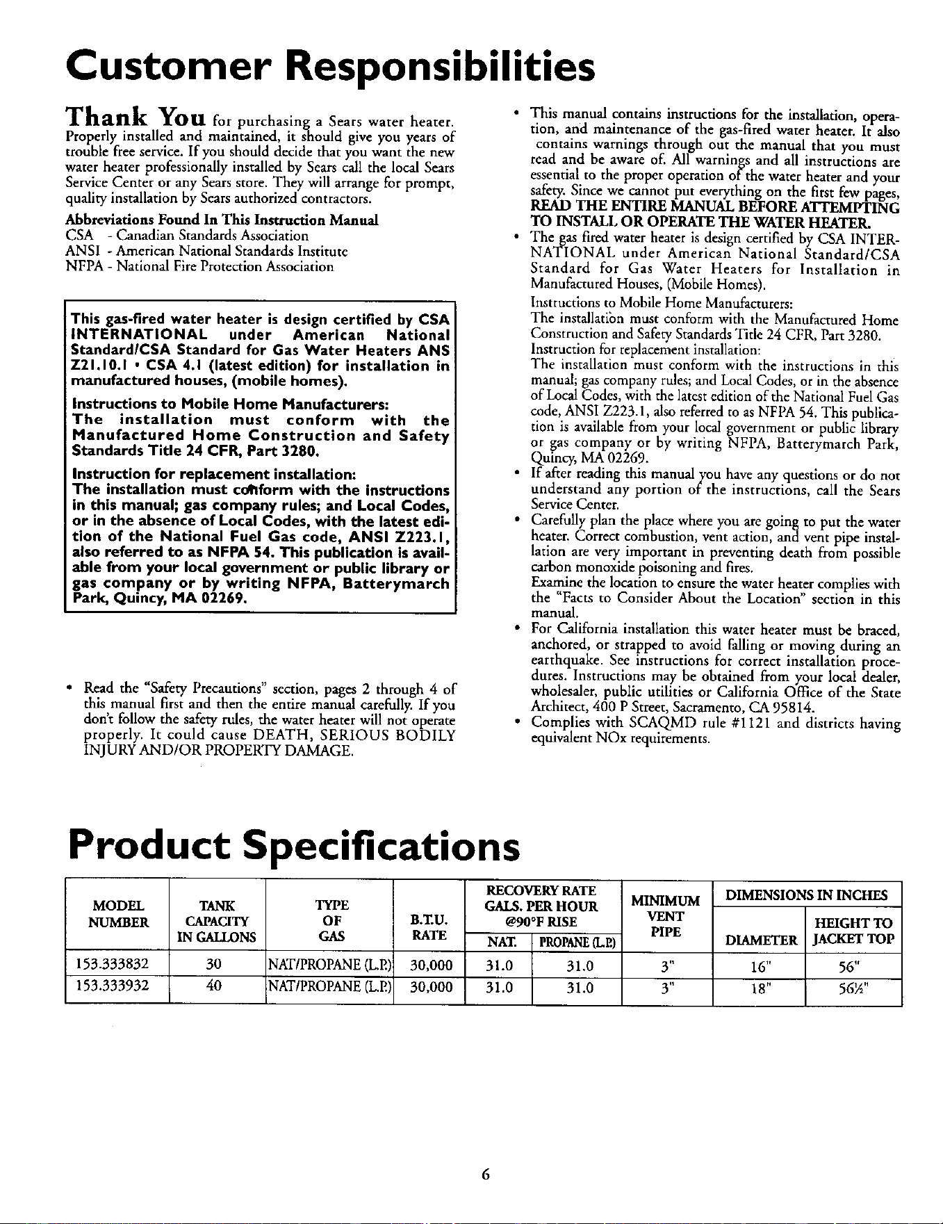
Product Specifications
MODEL
NUMBER
153.333832
153.333932
TANK
CAPACITY
IN GALLONS
30
40
TYPE
OF
GAS
NAT/PROPANE(L.P.)
NAT/PROPANE(L.P.
B.T.U.
RATE
30,000
3O,OOO
RECOVERYRATE
GALS. PER HOUR
@90°FRISE
NAT, PROPANE{L.E)
31.0 31.0
31.0 31.0
MINIMUM
VENT
PIPE
3 01
3"
DIMENSIONS IN INCHES
HEIGHT TO
DIAMETER JACKET TOP
16" 56"
18" 56½"
6
Materials and Basic Tools Needed
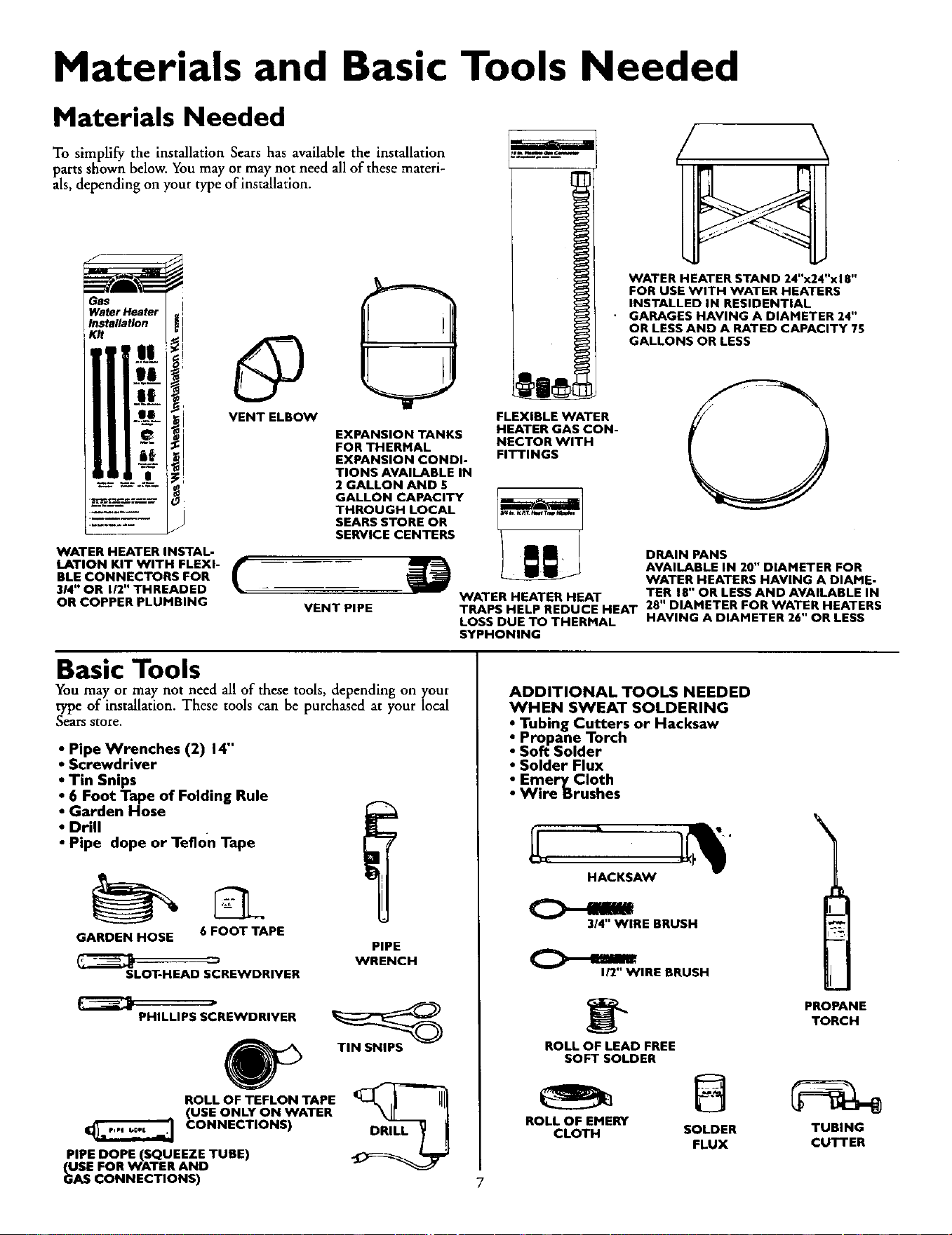
Materials Needed
To simplify the installation Sears has available the installation
parts shown below. You may or may not need all of these materi-
als, depending on your type of installation.
WATER HEATER INSTAL-
LATION KIT WITH FLEXI- f
BLE CONNECTORS FOR
3/4" OR I/2" THREADED
OR COPPER PLUMBING
VENT ELBOW
EXPANSION TANKS
FOR THERMAL
EXPANSION CONDI-
TIONS AVAILABLE IN
2 GALLON AND 5
GALLON CAPACITY
THROUGH LOCAL
SEARS STORE OR
SERVICE CENTERS
FLEXIBLE WATER
HEATER GAS CON-
NECTORWITH
FITTINGS
VENT PIPE
WATER HEATER STAND 24"x24"x18"
FOR USE WITH WATER HEATERS
INSTALLED IN RESIDENTIAL
• GARAGES HAVING A DIAMETER 24"
OR LESS AND A RATED CAPACITY 75
GALLONS OR LESS
DRAIN PANS
AVAILABLE IN 20" DIAMETER FOR
WATER HEATERS HAVING A DIAME-
WATER HEATER HEAT TER 18" OR LESS AND AVAILABLE IN
TRAPS HELP REDUCE HEAT 28" DIAMETER FOR WATER HEATERS
LOSS DUE TO THERMAL HAVING A DIAMETER 26" OR LESS
SYPHONING
Basic Tools
You may or may not need all of these tools, depending on your
type of installation. These tools can be purchased at your local
Sears store.
• Pipe Wrenches (2) 14"
• Screwdriver
• Tin Snips
• 6 Foot Tape of Folding Rule
• Garden Hose
• Drill
• Pipe dope or Teflon Tape
GARDEN HOSE 6 FOOT TAPE
SLOT-HEAD SCREWDRIVER
PIPE
WRENCH
PHILLIPS SCREWDRIVER
ROLL OF TEFLON TAPE
(USE ONLY ON WATER
CONNECTIONS)
PIPE DOPE (SQUEEZE TUBE)
(USE FOR WATER AND
GAS CONNECTIONS)
TIN SNIPS
ADDITIONAL TOOLS NEEDED
WHEN SWEAT SOLDERING
• Tubing Cutters or Hacksaw
• Propane Torch
• Soft Solder
• Solder Flux
• Emery Cloth
• Wire Brushes
HACKSAW
314"WIRE BRUSH
1/2"WIREBRUSH
ROLL OFLEAD FREE
SOFT SOLDER
PROPANE
TORCH
ROLL OF EMERY
CLOTH SOLDER TUBING
FLUX CUTTER
Installation Instructions
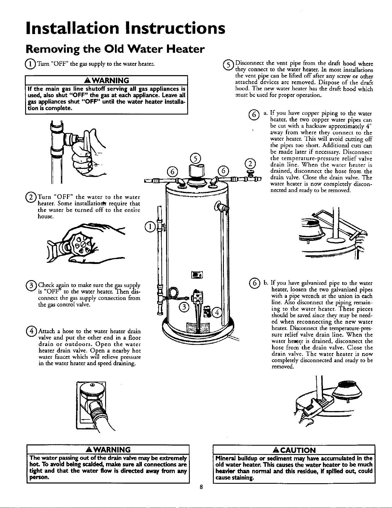
Removing the Old Water Heater
Turn "OFF" the gas supply to the water heater.
AWARNING 1
If the main gas line--all gasappliances is[
used,also shut "OFF" the gas at each appliance.Leave all [
gasappliances shut "OFF" until the water heater installa-[
tion iscomplete. ]
®
Turn "OFF" the water to the water
heater. Some installatiott_ require that
the water be turned off to the entire
house.
Q Check a_ain to make sure the gas supply
is OFF to the water heater. Then dis-
connect the gas supply connection from
the gas control valve.
®:
Attach hose the heater drain
a to water
valve and put the other end in a floor
drain or outdoors. Open the water
heater drain valve. Open a nearby hot
water faucet which will relieve pressure
in the water heater and speed draining.
Disconnect the vent pipe from the draft hood where
they connect to the water heater. In most installations
the vent pipe can be lifted off after any screw or other
attached devices are removed. Dispose of the draft
hood, The new water heater has the draft hood which
must be used for proper operation.
®
®
a.
If you have copper piping to the water
heater, the two copper water pipes can
be cut with a hacksaw approximately 4"
away from where they connect to the
water heater. This will avoid cutting off
the pipes too short. Additional cuts can
be made later if necessary, Disconnect
the temperature-pressure relief valve
drain line, When the water heater is
drained, disconnect the hose from the
drain valve. Close the drain valve. The
water heater is now completely discon-
nected and ready to be removed.
b.
If you have galvanized pipe to the water
heater, loosen the two galvanized pipes
with a pipe wrench at the union in each
line. Also disconnect the piping remain-
ing to the water heater. These pieces
should be saved since they may be need-
ed when reconnecting the new water
heater. Disconnect the temperature-pres-
sure relief valve drain line. When the
water heater is drained, disconnect the
hose from 'the drain valve. Close the
drain valve. The water heater is now
completely disconnected and ready to be
removed.
. AWARNING ]
The water passing ou_valve may be extremely [
hot. To avoid being scalded, make sure all connections are I
tight and that the water flow is directed away from any [
person. [
. ACAUTION
Mineral buildupor sediment may have accumulatedin the
old water heater. This causesthe water heater to be much
heavier than normal and this residue, if spilled out, could
causestainng.
Installation Instructions (cont'd)
Facts to Consider About the
Location
Whether replacing an old water heater or putting the water
heater in a new location, the following critical points must be
observed.
This mobile home gas-fired water heater is for use in a mobile
home. You should carefully choose an indoor location for the
new water heater, because the placement is a very important
consideration for the safety of the occupants in the building
and for the most economical use of the appliance. This water
heater is for use only in mobile homes and is not intended
for outdoor installation.
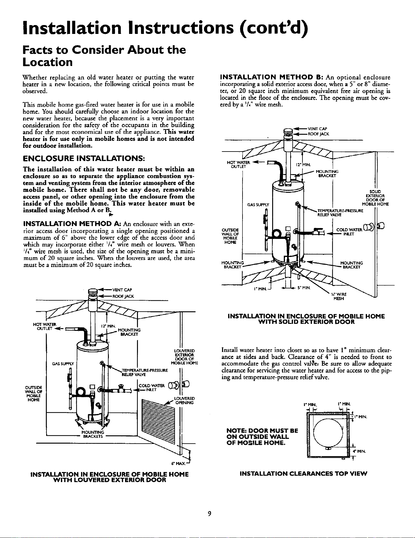
INSTALLATION METHOD B: An optional enclosure
incorporatinga solid exter'or access door, when a 5"or 8' diame-
ter, or 20 square inch minimum equivalent free air opening is
located in the floor of the enclosure. The opening must be cov-
ered by a V/' wire mesh.
ENCLOSURE INSTALLATIONS:
The installation of this water heater must be within an
enclosure so as to separate the appliance combustion sys-
tem and venting system from the interior atmosphere of the
mobile home. There shall not be any door, removable
access panel, or other opening into the enclosure from the
inside of the mobile home. This water heater must be
installed using Method A or B.
_r
INSTALLATION METHOD A: An enclosure with an exte-
rior access door incorporating a single opening positioned a
maximum of 6" above the lower edge of the access door and
which may incorporate either V, wire mesh or louvers. When
V," wire mesh is used, the size of the opening must be a mini-
mum of 20 square inches. When the louvers are used, the area
must be a minimum of 20 square inches.
HOT WATER .,el[----
OUTLET
BRACKET
SOLID
EXTERIOR
DOOR OF
WIRE
MESH
HOT WATER
OUTLET
OUTSID_
WALL OF
MOEdLE
HOME
MOUNTING
BRACKET
GAS SUP_Y
LOUVERED
EXTERIOR
DOOR OF
MOB_UE HOME
co._WA_RC_
L_/VEI_D
INSTALLATION IN ENCLOSURE OF MOBILE HOME
WITH LOUVERED EXTERIOR DOOR
INSTALLATION IN ENCLOSURE OF MOBILE HOME
WITH SOLID EXTERIOR DOOR
Install water heater into closet so as to have 1" minimum clear-
ance at sides and back. Clearance of 4" is needed to front to
accommodate the gas control val'_e,Be sure to allow adequate
clearance for servicing the water heater and for access to the pip-
ing and temperature-pressure relief valve.
NOTE: DOOR MUST BE
ON OUTSIDE WALL
OF MOglLE HOME.
I" MIN I" MIN.
I" MIN.
4" MIN,
INSTALLATION CLEARANCES TOP VIEW
Installation Instructions (cont'd)
Facts to Consider About the
Location (cont'd)
_,WARNING
Minimum clearancesbetween the water heater and com-
bustibleconstructionare I" at the sidesand rear, 4" at the
front,and6"from the vent pipe.Clearancefromthe top of the
jacketis12"onmostmodels.Note that a lesserdimensionmay
be allowedon somemodels.Referto the label on the water
heateradjacentto the gascontrolvalvefor all clearances.
The water heater should be secured to the floor and to the wall
of the enclosure with the mounting brackets provided. For
bracket location refer to "Securing Water Heater to Floor and
Wall" in the "Installation Instructions" section.
When a mobile home is skirted, an air intake opening with a
minimum free area of 32 square inches must be provided in the
skirt. If the opening is covered by louvers or screen, the total free
area must be 32 square inches. Other gas fired appliances in the
home will require additional free air openings; consult these
manufacturers for correct sizing.
A, W_,RNING
A gaswater heatercannotoperate properlywithoutthe cot-
amountof air for combustion.Do not installin a confined
areasuchacloset,unlessyouprovideairasshowninthe "Facts
to ConsiderAbout the Location" sectionon page9. Never
obstructthe flow of ventilationair. If youhaveanydoubtsor
questionsat all,callyour gascompanyorSearsServiceCenter.
Failureto providethe proper amount of combustionair can
resultin a fire or explosionand can causeDEATH, SERIOUS
BODILYINJUR_,OR PROPERTYDAMAGE.
AWARNING
When the systemrequires water at temperatureshigherthan
required for other uses,the hot water systemmay requirea
meanssuchas a mixingvalve to be installedto temper the
water at certainpointsofuse.Somepeopleare more likelyto
he permanentlyinjuredby hotwater than others;theseinclude
the elderly,children,the infirm,or the physically/mentallyhand-
icapped.Beforeimmersingyourselfor anyoneelseinhotwater,
he sureto checkthe water temperature. WARNING: HOT-
TER WATER INCREASES THE RISK OF SCALD INJURY.
(Alsosee "Temperature Regulation"section)Mixingvalvesare
availableat plumbingsupplyor hardwarestores. Followmanu-
facturersinstructionsfor installationofthesevalves.
AWARNING I
Thiswater heater shallnot be connectedto any heatingsys-I
ternsor component(s)previouslyusedwith a nonpotable water
heatingapp ance.
AWARNING
Ifthiswaterheater willhe usedin beautyshops,barbershops,
cleaningestablishments,or self-servicelaundrieswith dry
cleaningequipment,it is imperativethat the water heater or
water heatersbe installedso that combustionandventilation
air he taken from outsidethese area_ Referto the "Facts to
ConsiderAboutthe Location"sectionof this manualand also
the latestedition ofthe NationalFuelGasCode,ANSI 7.223.1
alsoreferredto asNFPA 54 for specifiesprovided€onceroin
air required.
AWARNING I
Toxicchemicalssuchas usedfor treatment of boilersor non- I
potablewater heatingappliancesshallneverhe introducedinto
a potabe water heatingsystem.
ACAUTION
WATER HEATERS EVENTUALLY LEAK: Installationof the
water heater must be accomplishedin sucha manner that if
the tank or any connectionsshouldleak,the flowof water will
not causedamageto the structure.When suchlocationscan-
not be avoided,a suitabledrain panshouldbe installedunder
the water heater.Drain pansare availableat your localSears
store. Sucha drain pan must benot greater than 1½inches
deep,have a minimum lengthand width of at least 2 inches
greaterthan the water heater dimensionsand must be piped
to anadequatedrain.The panmustnot restrict combustionair
flow.Under no circumstancesis the manufactureror Searsto
be held liablefor any water damagein connectionwith this
waterheater.
When a drain pan is required, the installation must conform to
"Method A" on page 9.
_,WARNING
INSTALLATIONSIN AREASWHERE FLAMMABLELIQUIDS
VAPORS) ARE LIKELY TO BE PRESENT OR STORED
GARAGES, STORAGE, AND UTILITY AREAS, ETC):
Flammableliquids(suchas gasoline,solvents,propane(LP) or
butane, etc.), all of whichemit flammable vapors,may be
improperlystoredor usedin suchareas.The gaswater heater
pilotlightor mainburnercanignitesuchvapors.The resulting
flashbackandfire cancausedeathor seriousburnsto anyonein
the area,aswellaspropertydamage.
If installationinsuch areasisyouronlyoption,then the installa-
tion must be accomplishedin a waythat the pilot flame and
mainburnerflameare elevatedfromthe floorat least18inches.
While this mayreduce the changesof flammablevaporsfroma
floorspillbeingignited,gasolineandotherflammablesubstances
shouldneverbestored or usedin the sameroom or areacon-
taininga gaswater heateror otl_eropenflameorsparkproduc-
ingappliance.
NOTE: Flammablevaporsmayhe drawnby air currentsfrom
otherareasofthe structureto the appliance.
_,WARNING
Propellantsof aerosolspraysand volatilecompounds,(clean-
ers,chlorinebasedchemicals,refrigerants, etc.) in additionto
beinghighlyflammablein manycases,will alsochangeto cor-
rosive hydrochloricacid when exposedto the combustion
productsof the water heater.The results can he hazardous,
and alsocauseproductfailure.
A, WARNING
This water heatermust not he installeddirectlyon carpeting.
Carpeting must be protected by a metal or wood panel
beneaththe applianceextending beyondthe full width and
depthof the applianceby at least3 inches(76.2mm) in any
direction,or if the appliance isinstalledin an alcoveor closet,
theentire floormustbe coveredby the panel.Failureto heed
this warningmayresultinaErehazard.
10
Installation Instructions (cont'd)
Securing Water Heater to
Floor and Wall
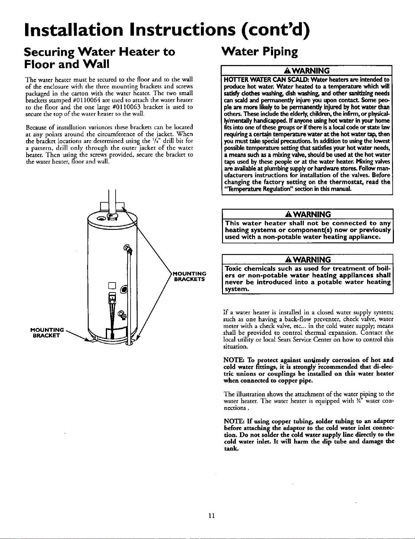
The water heater must be secured to the floor and to the wall
of the enclosure with the three mounting brackets and screws
packaged in the carton with the water heater. The two small
brackets stamped #0110064 are used to attach the water heater
to the floor and the one large #0110063 bracket is used to
secure the top of the water heater to the wall.
Because of installation variances these brackets can be located
at any points around the circumference of the jacket. When
the bracket locations are determined using the _/s" drill bit for
a pattern, drill only through the outer jacket of the water
heater. Then using the screws provided, secure the bracket to
the water heater, floor and wall.
Water Piping
A, WARNING
HOTTER WATER CAN SCALD: Water heaters are intended to
produce hot water, Water hea.t._.l.to a temperature which will
satisfyclothes washing,dish washing,and other sanitizingneeds
can scald and permanently injure you upon contact. Some peo-
ple are more likely to be permanently injured by hot water than
others. These includethe elderly,children,the infirm, or physical-
ly/mentally handicapped.If anyone usinghot water in your home
fits into one of these groupsor ifthere isa localcode or state law
requiringa certain temperature water at the hot water _ then
you must take specialprecautions.In addition to usingthe lowest
possibletemperature setting that satisfies your hot water needs,
a means suchasa mixing valve, shouldbe used at the hot water
taps used by these people or at the water heater, Mixing valves
are availableat plumbingsupplyor hardware stores.Follow man-
ufacturers instructions for installation of the valves. Before
changing the factory setting on the thermostat, read the
'q'emperature Regulation" sectionin this manual.
BRACKET
AWARNING I
This water heater shall not be connected to any I
heating systems or component(s) now or previously
used w th a non-potab e water heating app lance.
MOUNTING
BRACKETS
_,WARNING J
Toxic chemicals such as used for treatment of boil- J
ers or non-potable water heating appliances shall J
never be introduced into a potable water heating
system.
If a water heater is installed in a closed water supply system;
such as one having a back-flow preventer, check valve, water
meter with a check valve, etc.., in the cold water supply; means
shall be provided to control thermal expansion. Contact the
local utility or local Sears Service Center on how to control this
situation.
NOTE: To protect against untimely corrosion of hot and
cold water fittings, it is strongly _ecommended that all-elec-
tric unions or couplings be installed on this water beater
when connected to copper pipe.
The illustration shows the attachment of the water [iping to the
water heater. The water heater is equipped with ¾" water con-
nections.
NOTE: If using copper tubing, solder tubing to an adapter
before attaching the adaptor to the cold water inlet connec-
tion. Do not solder the cold water supply line directly to the
cold water inlet. It will harm the dip tube and damage the
tank.
11
Installation Instructions (cont'd)
Water Piping (cont'd)
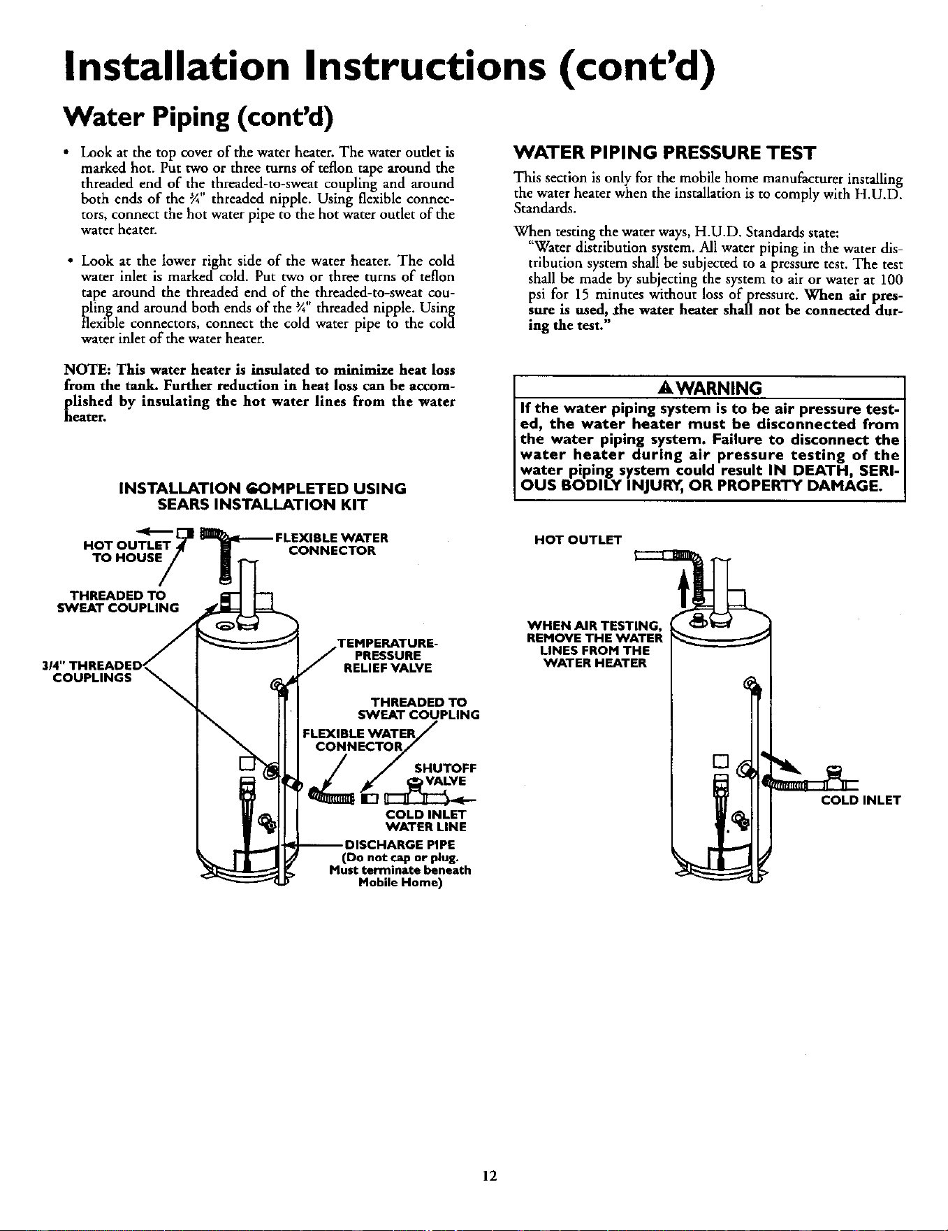
• Look at the top cover of the water heater. The water outlet is
marked hot. Put two or three turns of teflon tape around the
threaded end of the threaded-to-sweat coupling and around
both ends of the ¾ threaded nipple. Using flexible connec-
tors, connect the hot water pipe to the hot water outlet of the
water heater.
• Look at the lower right side of the water heater. The cold
water inlet is marked cold. Put two or three turns of teflon
tape around the threaded end of the threaded-to-sweat cou-
pling and around both ends of the ¾" threaded nipple. Using
exible connectors, connect the cold water pipe to the cold
water inlet of the water heater.
WATER PIPING PRESSURE TEST
This section is only for the mobile home manufacturer installing
the water heater when the installation is to comply with H.U.D.
Standards.
Wh,,en testing the water ways, H.U.D. Standards state:
Water distribution system. All water piping in the water dis-
tribution system shall be subjected to a pressure test. The test
shall be made by subjecting the system to air or water at 100
psi for 15 minutes without loss of pressure. When air pres-
sure is used, she water heater shall not be connected dur-
ing the test."
NOTE: This water heater is insulated to minimize heat loss
from the tank. Further reduction in heat loss can be accom-
plished by insulating the hot water lines from the water
_l.t er.
INSTALLATION GOMPLETED USING
SEARS INSTALLATION KIT
AWARNING
If the water piping system is to be air pressure test-
ed, the water heater must be disconnected from
the water piping system. Failure to disconnect the
water heater during air pressure testing of the
water piping system could result IN DEATH, SERI-
OUS BODILY INJURY, OR PROPERTY DAMAGE.
HOT OUTLET
HOT OUTLET
TO HOUSE
CONNECTOR
THREADED TO
SWEAT COUPLING
3/4"THREADED
COUPLINGS
PRESSURE
RELIEF VALVE
THREADED TO
SWEAT COUPLING
SHUTOFF
VALVE
COLD INLET
WATER LINE
(Do not cap or plug.
Must terminate beneath
Mobile Home)
WHEN AIR TESTING, :
REMOVE THE WATER
LINES FROM THE
WATER HEATER
COLD INLET
12
Installation Instructions (cont'd)
Temperature-Pressure Relief Valve
AWARNING
At the time of manufacturethis water heater wasprovided
with a combinationtemperature-pressuresreliefvalvecertified
bya nationally recognized testing laboratorythat maintains
_riodic inspectionof productionof listedequipmentor mate-
rials, as meeting the requirements for Relief Valves and
AutomaticGasShutoffDevicesfor Hot Water SupplySystems,
and the latest edition of ANSI Z21.22 andthe coderequire-
mentsof ASME. If replaced,the valvemust meet the require-
nentsoflocal codes,butnot lessthanacombinationtempera-
tere andpressurereliefvalvecertifiedasmeetingthe require-
mentsfur ReliefValvesand AutomaticGasShutoffDevicesfor
Hot Water SupplySystems,ANSI Z21.22bya nationally recog-
nizedtestinglaboratorythat maintainsperiodicinspectionof
)reductionof listedequipmentor materials.
The valvemust be marked with a maximum set pressurenot
to exceed the marked hydrostaticworking pressureof the
water heater(150 Ibsdsq.in.)and a dischargecapacitynot less
thanthe water heaterinputrate asshownonthe model rating
plate. (Electricheaters- watts dividedby 1000x 3415 equal
BTU/Hn rate.)
Yourlocaljurisdictionalauthori_, whilemandatingthe useof a
temperature-pressure relief vaivecomplyingwithANSI Z21.22
and ASME, mayrequire a valvemodeldifferent from the one
furnishedwiththe water heater
Compliancewith suchlocalrequirements mustbe satisfiedby
the i_ier or enduserof the water heaterwith a locallypre-
scribedtemperature-pressurereliefvalveinstalledinthe desig-
natedopeningin the water heaterin placeof the factoryfur-
nishedvalve.
Forsafeoperationofthe water heater,tile reliefvalvemustnot
beremovedfrom it'sdesignatedopeningor plugged.
The temperature-pressurereliefvalvemustbe installeddirectly
intothe fittingofthe water heaterdesignatedforthe relief valve.
Posi_ontbovalvedownwardandprevidetubingso that any dis-
chargewill exit only within6 inchesabove,or at any distance
below the structuralfloor Be certain that no contactis made
withanyliveelectricalpart.The dischargeopeningmust not be
blockedor reduced in sizeunderany circumstances.Excessive
length,over30 feet, or useof morethanfour elbowscan cause
R_lrictionandreducethe dischargecapacityof the valve.
No valveor otherobstructionisto beplacedbetweenthe relief
valveand the .,t_n,k. Do not connecttubingdirectlyto discharge
drainunlessa6 airgapisprovided.Topreventbodilyinlury, haz-
ardto life,or propertydamage,the relief valvemustbeallowed
to dischargewaterinquantitiesshouldcircumstancesdemand.If
the dischargepipe isnot connectedto a drainor other suitable
means,the water flowmaycausepropertydamage.
"heDischargePipe:
Mustnot be smallerin sizethan the outlet pipe sizeof the
valve,orhaveany reducingcouplingsor other restrictions.
Mustnot bepluggedor Mocked.
Mustbeof material listedforhotwater distribution.
Mustbe installedso as to allow complete drainageof both
the temperaturo-pressurerelief valve, and the discharge
pipe.
Mustterminateat an adequatedrain.
Mustnot haveanyvalvebetweenthe relief valveandtank.
AWARNING
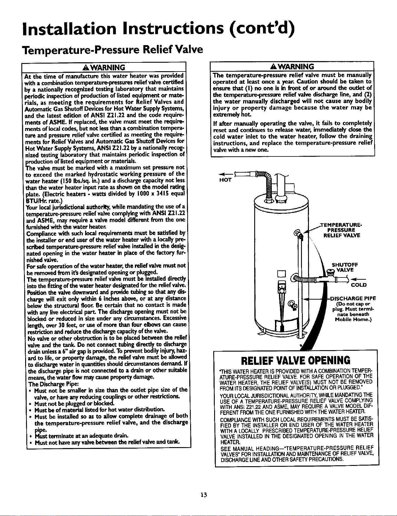
The temperature-pressure relief valve must be manually
operated at least once a year.Caution shouldbe taken to
ensurethat (I) no one is in front of or aroundthe outlet of
the temperature-pressurerelief valvedischargeline, and (2)
the water manually dischargedwill not cause any bodily
injury or property damage because the water may be
extremely hot.
If after manuallyoperating the valve,it failsto completely
resetand continuesto release water, immediately closethe
cold water inlet to the water heater, follow the draining
instructions,and replace the temperature-pressure relief
valvewith a new one.
HOT
PRESSURE
RELIEF VALVE
SHUTOFF
VALVE
:OLD
PE
(Do not cap or
plug, Must termi-
nate beneath
Mobile Home,)
RELIEFVALVEOPENING
"THISWATERHEATERISPROV}DEDWITHA COMBINATIONTEMPER-
ATURE-PRESSURERELIEFVALVE.FORSAFEOPERATIONOF THE
WATERHEATER,THE RELIEFVALVE(S)MUST NOTBE REMOVED
FROMITSDESIGNATEDPOINTOFiNSTALLATIONORPLUGGED."
YOURLOCALJURISDICTIONALAUTHORITY,WHILEMANDATINGTHE
USE OF A TEMPERATURE-PRESSURERELIEFVALVECOMPLYING
WITHANSI Z.21.22ANDASME, MAYREQUIREA VALVEMODELDIF-
FERENTFROMTHEONEFURNISHEDWITHTHEWATERHEATER.
COMPLIANCEWITHSUCHLOCALREQUIREMENTSMUSTBESATIS-
FIEDBY THEINSTALLEROR ENDUSEROF THE WATERHEATER
WITHA LOCALLYPRESCRIBEDTEMPERATURE-PRESSURERELIEF
VALVEINSTALLEDINTHE DESIGNATEDOPENINGIN THE WATER
HEATER.
SEE MANUALHEADING--=TEMPERATURE-PRESSURERELIEF
VALVES"FORINSTALLATIONANDMAINTENANCEOFRELIEFVALVE,
DISCHARGELINEANDOTHERSAFETYPRECAUTIONS,
13
Installation Instructions (cont'd)
Filling the Water Heater
A CAUTION
Never use this water heater unless it is completely filled with
[ water. To prevent damage to the tank, the tank must be filled
[ with wate_ Water must flow from the hot water faucet
I before turning "ON" gasto the water heater.
To fill the water heater with water:
• Close the water heater drain valve by turning the handle to
the right (clockwise). The drain valve is on the lower front of
the water heater.
Open the cold water supply valve to the water heater.
NOTE: The cold water supply valve must be lefx open
when the water heater is in use.
To insure complete filling of the tank, allow air to exit by
opening the nearest hot water faucet. Allow water to run
until a constant flow is obtained. This will let air out of the
water heater and the piping.
• Check all new water piping for leaks.Repairas needed.
Venting
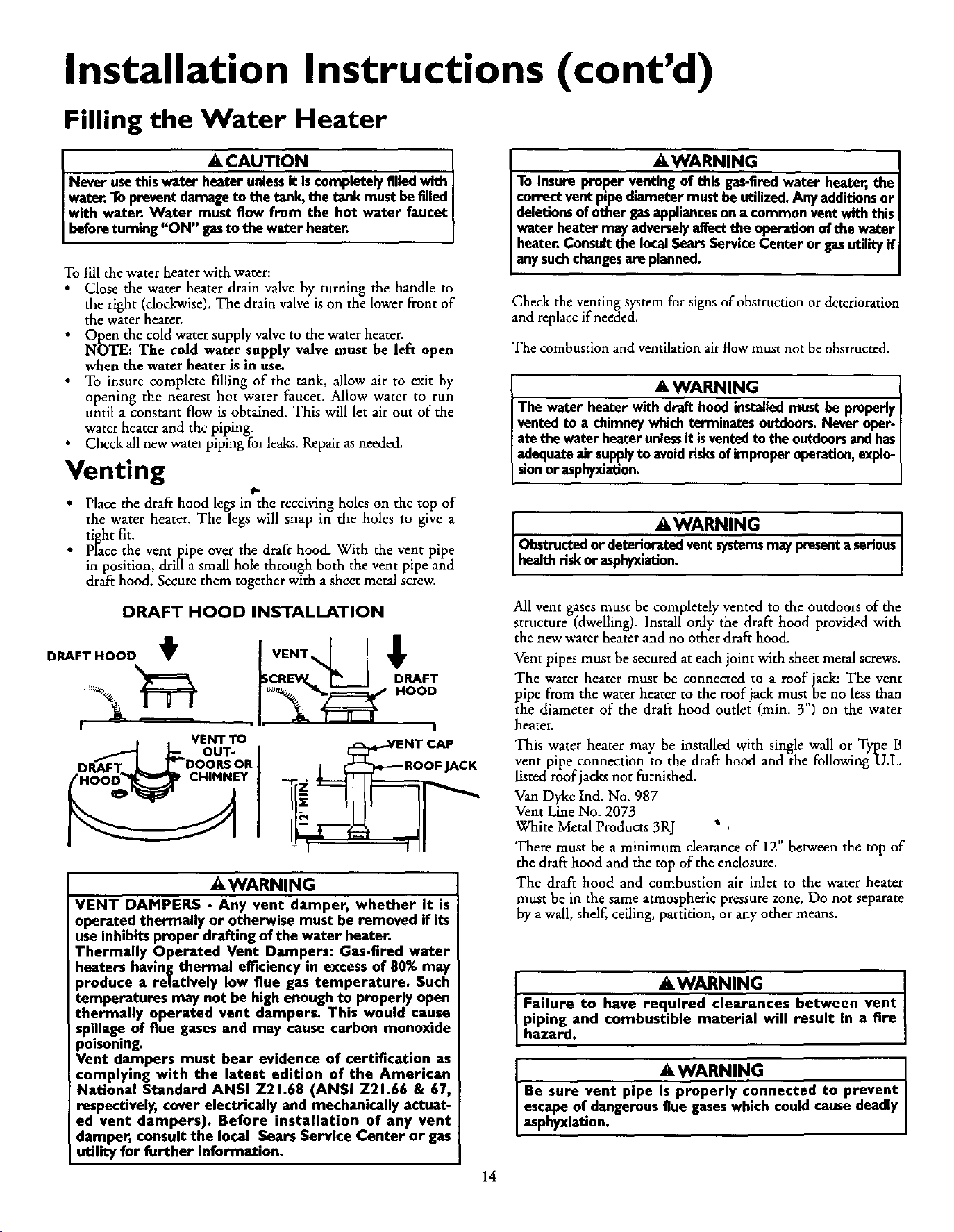
• Place the draft hood legs in the receiving holes on the top of
the water heater. The legs will snap in the holes to give a
tight fit.
• Place the vent pipe over the draft hood. With the vent pipe
in position, drill a small hole through both the vent pipe and
draft hood. Secure them together with a sheet metal screw.
DRAFT HOOD INSTALLATION
DRAFTHOOD # VENT J. [
'_% _ ;CREW_. [_ I DRAFT
,
VENT TO _¢ENT CAPOUT. I
DRAFT_ • _-_ DOORSOR| l _4_ ROOF JACK
_ I _fHOOD_ CHIMNEY [ !_T_______ i_
AWARNING
VENT DAMPERS - Any vent damper, whether it is
operated, thermally or otherwise must be removed if its
use inhibits proper drafting of the water heater.
Thermally Operated Vent Dampers: Gas-fired water
heaters having thermal etficiency in excess of 80% may
woduce a relatively low flue gas temperature. Such
temperatures may not be high enough to properly open
thermally operated vent dampers. This would cause
spillage of flue gases and may cause carbon monoxide
_oisoning.
Vent dampers must bear evidence of certification as
complying with the latest edition of the American
National Standard ANSI Z21.68 (ANSI Z21.66 & 67,
respectively, cover electrically and mechanically actuat-
ed vent dampers). Before installation of any vent
damper, consult the local Sears Service Center or gas
utility for further information.
AWARNING
!To insure proper venting of this gas-fired water heater, the
correct vent pipe diameter must be utilized. Any additions or
deletions of other gas appliances on a common vent with this
water heater may adversely affect the operation of the water
heater. Consult the local Sears Service Center or gas utility if
any such changes are planned.
Check the venting system for signs of obstruction or deterioration
and replace if needed.
The combustion and ventilation air flow must not be obstructed.
AWARNING l
The water heater with_led must be
properlyI
vented to a chimney which"'" '"terminates outdoors, Never oper. [
ate the water heater unlessit is vented to the outdoors and has/
adequate air supplyto avoid risksof improper operation, explo- [
sion or asphyxiation. J
A WARNING
Obstructed or deteriorated vent systemsmay present a serious
health risk or asphyxiation.
All vent gases must be completely vented to the outdoors of the
structure (dwelling). Installonly the draft hood provided with
the new water heater and no other draft hood.
Vent pipes must be secured at each joint with sheet metal screws.
The water heater must be connected to a roof jack: The vent
pipe from the water heater to the roof jack must be no less than
the diameter of the draft hood outlet (min. 3") on the water
heater.
This water heater may be installed with single wall or Type B
vent pipe connection to the draft hood and the following U.L.
listed roof jacks not furnished.
Van Dyke Ind. No. 987
Vent Line No. 2073
White Metal Products 3RJ *,
There must be a minimum clearance of 12" between the top of
the draft hood and the top of the enclosure.
The draft hood and combustion air inlet to the water heater
must be in the same atmospheric pressure zone. Do not separate
by a wall, shelf, ceiling, partition, or any other means.
A WARNING
Failure to have required clearances between vent
piping and combustible material will result in a fire
hazard.
.AWARNING
Be sure vent pipe _s properly connected to prevent
escapeof dangerousflue gaseswhich could cause deadly
asphyxiat on.
14
Installation Instructions (cont'd)
Venting (cont'd)
AWARNING
Chemical vapor corrosion of the flue and vent system
may occur if air for combustioncontains certain chemical
vapors.Spray canpropellants, cleaningsolvents,refrigera-
tor and air conditioner refrigerants, swimming pool
chemicals, calcium and sodium chloride, waxes, bleach
and process chemicals are typical compoundswhich are
Ipotentially corrosive.
Gas Piping
.&WARNING
Make sure the gas suppliedis the same type listed on the
model rating plate. The inlet gaspressuremust not exceed
10.5in.water column(2.6kPa)for naturalgasor 13in. water
column (3.2kPa)for propane(LP.) gas.The minimum inlet
gaspressurelistedon the model rating plate isfor the pur-
poseofinputadjustment.
I AWA.RNING
fithe gascontrol valveis sublectedto pressuresexceeding½[
poundper squareinch(3.5kPa),the damageto the gascon-I
trol valvecouldresultm a fireor explosionfrom leakinggas. I
AWARNING
If the main gasline shutoffserving all gasappliancesis used,
alsoturn "OFF" the gasat eachappliance. Leaveallgasappli-
ancesshutoffuntilthe water heaterinstallationiscomplete.
A gas line of sufficient size must be run to the water heater.
Consult the latest edition of National Fuel Gas Code ANSI
Z223.1, also referred to as NFPA 54 and the gas company con-
cerning pipe size.
There must be:
• A readily accessible manual shut offvalve in the gas supply line
serving the water heater, and
• A drip leg (sediment trap) ahead of the gas control valve to help
prevent dirt and foreign materials from entering the gas control
valve.
• A flexible gas connector or a ground joint union between the
shutoffvalve and control valve to permit servicing of the unit.
AWARNING I
The appliance and its gas connectionmust be leak tested
beforeplacngthe app ance n operaton.
AWARNING
• The applianceandits individualshutoffvalvemustbe discon-
necteclfromthe gassupplypipingsystemduringanypressure
testing of the gas systemat test pressuresin excessof V2
pound per squareinch(3.5kPa).
• The appliancemustbeisolatedfrom the gassupplypipingsys-
tem by closingits individualmanualshutoffvalveduringany
pressuretestingof the gassupplypipingsystemat test pres-
suresequalor lessthan ¼poundpersquareinch(3.5kPa).
AWARNING
Use pipe joint compound or teflon tape marked as being
resistant to the actionofpetro eum[Propane(LR)] gases.
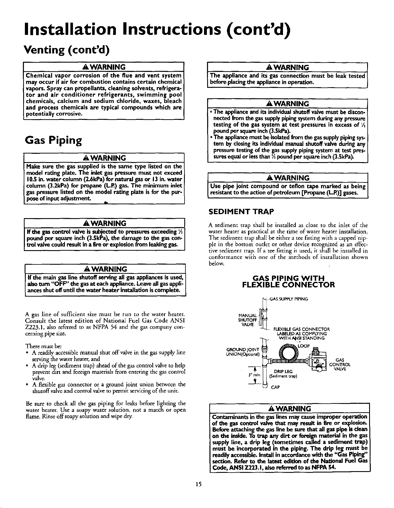
SEDIMENT TRAP
A sediment trap shall be installed as close to the inlet of the
water heater as practical at the time of water heater installation.
The sediment trap shall be either a tee fitting with a capped nip-
ple in the bottom outlet or other device recognized as an effec-
tive sediment trap. If a tee fitting is used, it shall be installed in
conformance with one of the methods of installation shown
below.
GAS PIPING WITH
FLEXIBLE CONNECTOR
GROUND JOINT
UNION(Optional)
._-_ GAS SUPPLY PIPING
MANUAL
SHUTOFF
VALVE
FLEXIBLEGAS CONNECTOR
LABELEDAS COMPLYING
WITH ,_SI STANDING
LOOP
GAS
CONTROL
_ VAkVE
DRIP LEG
3" rain. (Sediment trap)
CAP
Be sure to check all the gas piping for leaks before lighting the
water heater. Use a soapy water solution, not a matcn or open
flame. Rinse offsoapy solution and wipe dry:
AWARNING
Contaminantsin the gaslinesmaycauseimproper operation
of the gascontrol valvethat may result in Ere or explosion.
Beforeattachingthe gasline be sure that all gaspipe isdean
on the inside.Totrap any dirt or foreign material in the gas
supplyline, a drip leg (sometimes called a sediment trap)
must be incorporated in the piping. The drip leg must be
readily accessible.Installin accordancewith the "Gas Piping"
section.Refer to the latest edition of the National Fuel Gas
ICode,ANSI Z223.1,alsoreferredto as NFPA54.
15
Installation Instructions (cont'd)
"Fuel" Conversion Instruc-
tions From Natural Gas To
Propane (L.P.) Gas
_,WARNING
This water heater hasbeen factory equipped to operate
with the type gasindicated in the "EQUIPPED FOR" area
of the model rating plate located near the gas control
valve. The indicated _as may be either Natural or
Propane (L.R). By followingthe conversioninstructions in
this manualor the instructionsnear the gas control valve,
the water heater must be converted if it is to be used
with the opposite gas. DO NOT USE THIS WATER
HEATER WITH ANY GAS OTHER THAN THE ONE
LISTED ON THE MODEL RATING PLATE. Failure to use
the correct gas can cause problems which can result in
DEATH, SERIOUS BODILY INJURY, OR PROPERTY
DAMAGE. If you have any questions or doubts consult
yourgassupplier or gascompany.
Read and follow detailed con_mion instructions located on the
water heater and also in this manual in their entirety before starting
the conversion.
Conversion kit with necessary parts are in a bag attached to the
drain valve.
Step 1. Turn gas control knob "A"to "PILOT". Depress and turn
"OFF_'. (See Figure 1, page 17).
Step 2. Remove outer and inner access doors from water heater.
Step 3. Remove burner _ssemblyfrom water heater and control by
loosening 3Anut H holding burner assembly to _ntrol.
(See Figure 2, pag_ !7). Loosen pilot tube nut J and
thermocouple nut K at control.
Step 4. Remove screws "D" disengaging manifold from burner
(See Figure 3, page 17)
• (g . • . 3 Ir
Step 5. Remove orifice E (See Figure 3, page 17) using ¼
wrench. Install orifice marked "L.P." found in the bag
into manifold. "l_ghten securely. Secure burner to mani-
fold with screws D .
Step 6. Loosen pilot tube nut "F" (See Figure 4, page 17). Re-
move orifice _G" and replace with blue colored orifice
found in bag. Reinstall nut F and tighten securely.
Step 7. Make sure all connections are tightened securely, and rein-
stall burner assembly into water heater. Position end of the
manifold inside bracket as shown in Figure 3 on page 17.
Reinstall manifold into control and tighten 3Anut ( H )
securely. Recheck to see that end of manifold is still inside
bracket as shown in Figure 3 on page 17. Reinstall pilot
tubing and thermocouple into control. (See Figure 2,
page 17)
Step 8. Place screwdriver in slot "B". (See Figure 1, page 17). De-
press and turn counter-clockwise (C'-'_ to stop• Con-
trol screw must be in "IN"position for propane (L.P.)gas
and in _OUT" position for natural gas. STOP! Read label
"ForYour Safety" located on your water heater.
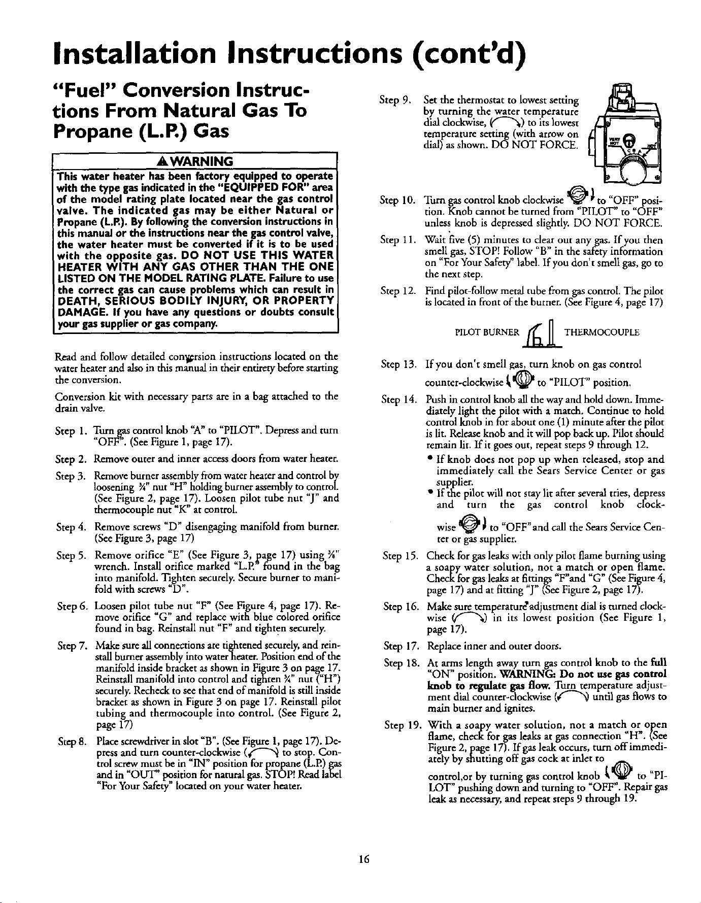
Step 9.
Step 10.
Step 11.
Step 12.
Step 13.
Step 14.
Step 15.
Step 16.
Step 17.
Step 18.
Step 19.
Set the thermostat to lowest setting
by turning the water temperature
dial clockwise, (_"_) to its lowest /_======_
temperature setting (with arrow on _ I1_ _ li
dial) as shown. DO NOT FORCE.
Turn gas control knob clockwise ___ to OFF posi-
tion. Knob cannot be turned from ' PILOT" to "OFF"
unless knob is depressed slightly. DO NOT FORCE.
Wait five (5) minutes to clear out anygas. If you then
smell gas, STOP! Follow "B" in the safety information
on "For Your Safety" label• If you don't smell gas, go to
the next step.
Find pilot-follow metal tube from gas control. The pilot
is located in front of the burner. (See Figure 4, page 17)
PILOT BURNER ._ THERMOCOUPLE
If you don't smell gas, turn knob on gas control
counter-clockwise _ to "PILOT"position.
Push in control knob all the way and hold down. Imme-
diately light thepilot with a match, Continue to hold
control knob in for about one (1) minute after the pilot
is lit. Release knob and it will pop back up. Pilot should
remain lit. If it goes out, repeat steps 9 through 12.
• If knob does not pop up when released, stop and
immediately call the Sears Service Center or gas
supplier.
• If the pilot will not stay lit after several tries, depress
and turn the gas control knob clock-
wise _ _ to "OFF"and call the Sears Service Cen-
ter or gas supplier.
Check for gas leaks with only pilot flame burning using
a soapy water solution, not a match or open flame.
Check for gas leaks at fittings "F"and _G" (See Figure4,
page 17) and at fitting "J"(See Figure2, page 17).
Make sure temperature'ad ustment dial is turned clock-
wise (_'_) in its lowest position (See Figure 1,
page 17).
Replace inner and outer doom.
At arms length away turn gas control knob to the full
_ON" position. WARNING: Do not use gas control
knob to regulate gas flow. Turn temperature adjust-
ment dial counter-clockwise (_-'x) until gas flows to
main burner and ignites.
With a soapy water solution, not a match or open
flame, check for gas leaks at gas connection _H_. (See
Figure 2, page 17). If gas leak occurs, turn offimmedi-
ately by shutting off gas cock at inlet to at_
control,or by turning gas control knob _ to PI-
LOT" pushing down and turning to OFF . Repair gas
leak as necessary, and repeat steps 9 through 19.
16
Installation Instructions (cont'd)
Step 20. At arm's length away, set the thermostat to desired set-
ting. The mark (V) HOT indicative of approx. 120°F is
preferred starting point. If hotter water is desired see the
_Temperature Regulation" section in this manual.
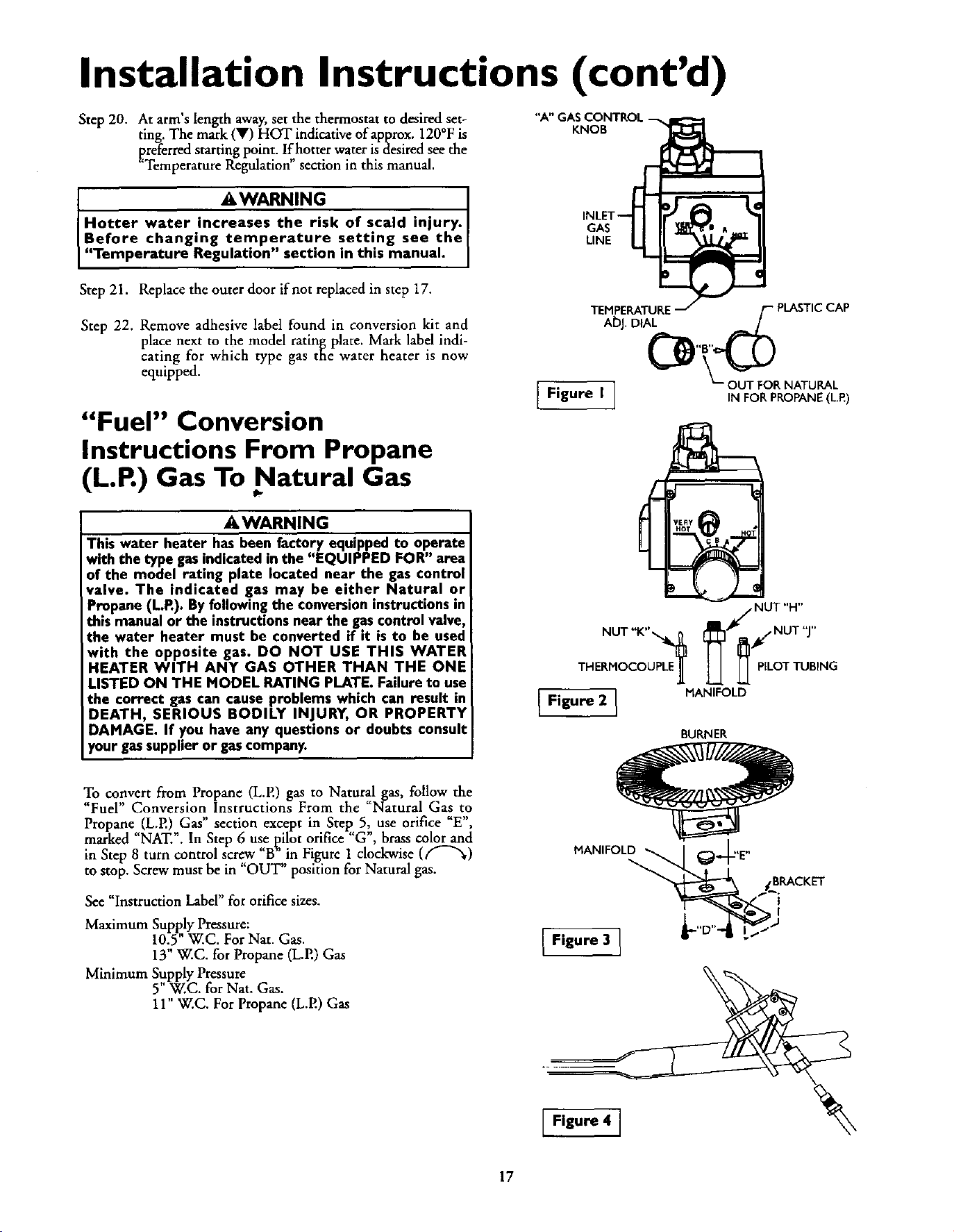
"A" GAS CONTROl
KNOB
_WARNING
Hotter water increases the risk of scald injury.
Before changing temperature setting see the
"Temperature Regulation" section in this manual.
GAS
LINE
Step 21. Replace the outer door if not replaced in step 17.
Step 22. Remove adhesive label found in conversion kit and
place next to the model raring place. Mark label indi-
cating for which type gas the water heater is now
equipped.
"Fuel" Conversion
Instructions From Propane
(L.P.) Gas To Natural Gas
TEMPERATURE /'- PLASTIC CAP
AbJ. DIAL -- /
g I
OUT FOR NATURAL
L Figure I ] IN FORPROPANE(L._)
A, WARNING
This water heater has been factory equipped to operate
with the type gas indicated in the "EQUIPPED FOR" area
of the model rating plate located near the gas control
valve. The indicated gas may be either Natural or
Propane (L.P.). By following the conversioninstructions in
this manual or the instructions near the g.ascontrol valve,
the water heater must be converted if it is to be used
with the opposite gas. DO NOT USE THIS WATER
HEATER WITH ANY GAS OTHER THAN THE ONE
LISTED ON THE MODEL RATING PLATE. Failure to use
the correct gas can cause problems which can result in
DEATH, SERIOUS BODILY INJURY, OR PROPERTY
DAMAGE. If you have any questions or doubts consult
your gassupplier or gas company.
To convert from Propane (L.E) gas to Natural gas, follow the
"Fuel" Conversion Instructions From the "Natural Gas to
Propane (L.E) Gas" section except in Step 5, use orifice "E",
marked NAT.. In Step 6 use pdot orifice G , brass co or and
in Step 8 turn control screw "B_ in Figure 1 clockwise (f'-_)
to stop. Screw must be in "OUT" position for Natural gas.
See "Instruction Label" for orifice sizes.
Maximum Supp,ly Pressure:
10.5 W.C. For Nat. Gas.
13" W.C. for Propane (L.P.) Gas
Minimum Supply Pressure
5 W.C. for Nat. Gas.
11" W.C. For Propane (L.P.)Gas
NUT "K" _I_UTN 'U_"J"
THERNOCOUPL_E _ _ PILOT TUBING
[FI B 21 MAN,FOLD
BURNER
,F,.ii 'ilL
IFig-- ]
17
Installation Instructions (cont'd)
Installation Checklist
BEFORE LIGHTING THE PILOT:
• Check the gas lines for leaks.
a. Use a soapy water solution. DO NOT test for gas leaks
usinga match or open flame.
b. Brush the soapy water solution on all gas pipes, joints and
fittings.
c. Chec'_ for bubbling soap. This means you have a leak.
Turn "OFF" gas andmake the necessary repairs.
d. Recheck for leaks.
e. Rinse off soapy solution and wipe dry.
• ls the new temperature-pressure relief valve properly installed
and piped to an adequate drain? See "Temperature-Pressure
Relief Valve ' sect'on.
• Are the cold and hot water lines connected to the water
heater correctly? See "Water Piping" instructions in the
"Installation Instructions" section.
• Is the water heater completely filled with water? See "Filling"
mstrucnons m the Installat on Instruct ons sect on.
• Will a water leak damage anything? See the "Facts to
Consider About the Location" section.
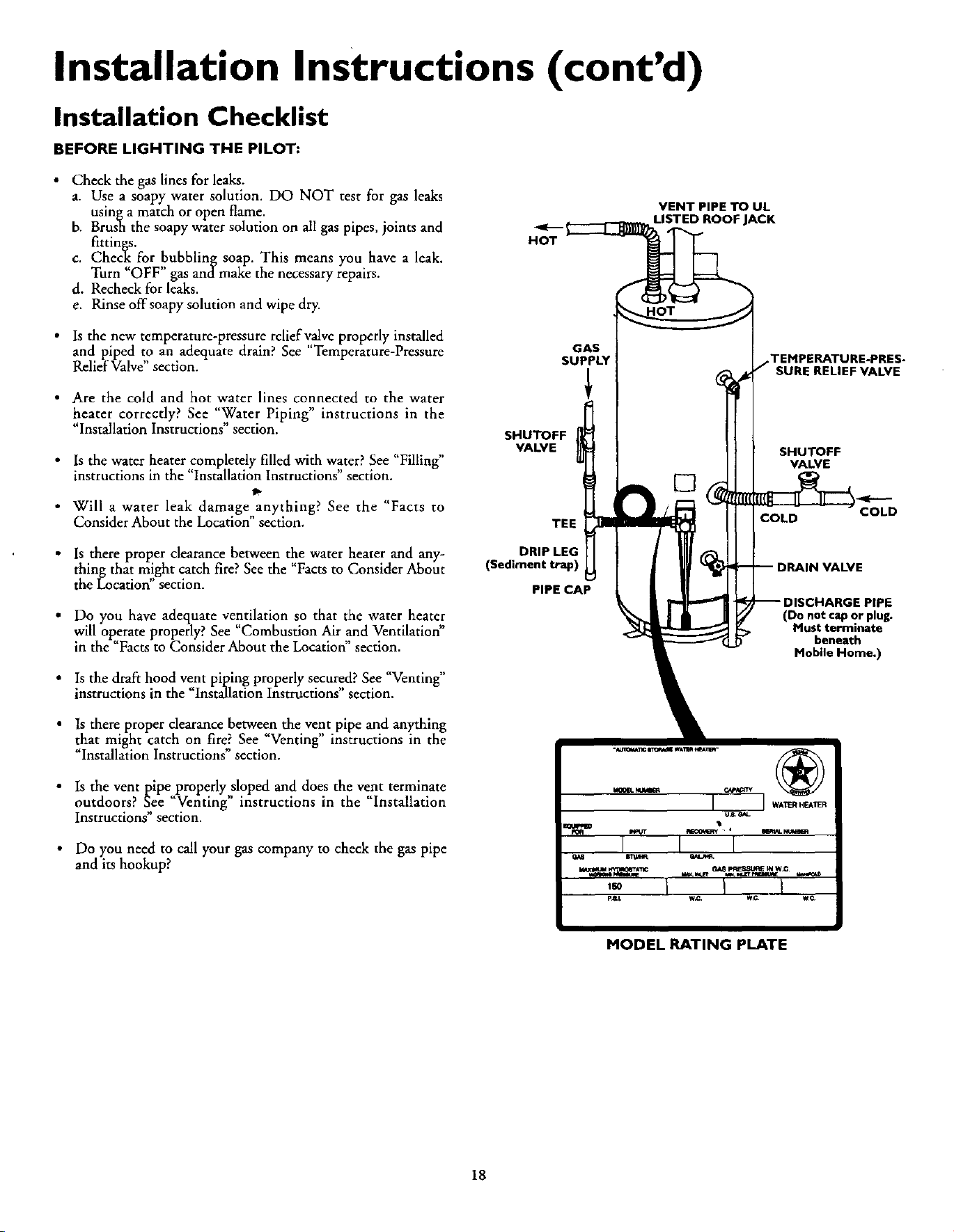
-.IF---
HOT
GAS
SUPPLY
SHUTOFF
VALVE
TEE
VENT PIPE TO UL
LISTED ROOF JACK
TEMPERATURE.PRES.
SURE RELIEF VALVE
SHUTOFF
VALVE
COLD COLD
• Is there proper clearance between the water heater and any-
thing that might catch fire? See the "Facts to Consider About
the Location" section.
• Do you have adequate ventilation so that the water heater
will operate properly? See "Combustion Air and Ventilation"
in the "Facts to Consider About the Location" section.
• Is the draft hood vent piping properly secured? See "Venting"
instructions in the "Installation Instructions" section.
DRIP LEG
(Sediment trap)
PIPE CAP
I VALVE
PIPE
(Do not cap or plug.
Must terminate
beneath
Mobile Home.)
• Is there proper clearance between the vent pipe and anything
that might catch on fire. See Venting mstrucnons m the
"Installation Instructions" section.
• Is the vent pipe, properlysloped and does the vent terminate
outdoors. See Ventmg mstructmns In the Installatmn
Instructions" section.
Do you need to call your gas company to check the gas pipe
and its hookup?
_ WA'P_ H_R
'= I I I
P_LI, W/_, W,C WC
MODEL RATING PLATE
18
Operating Instructions
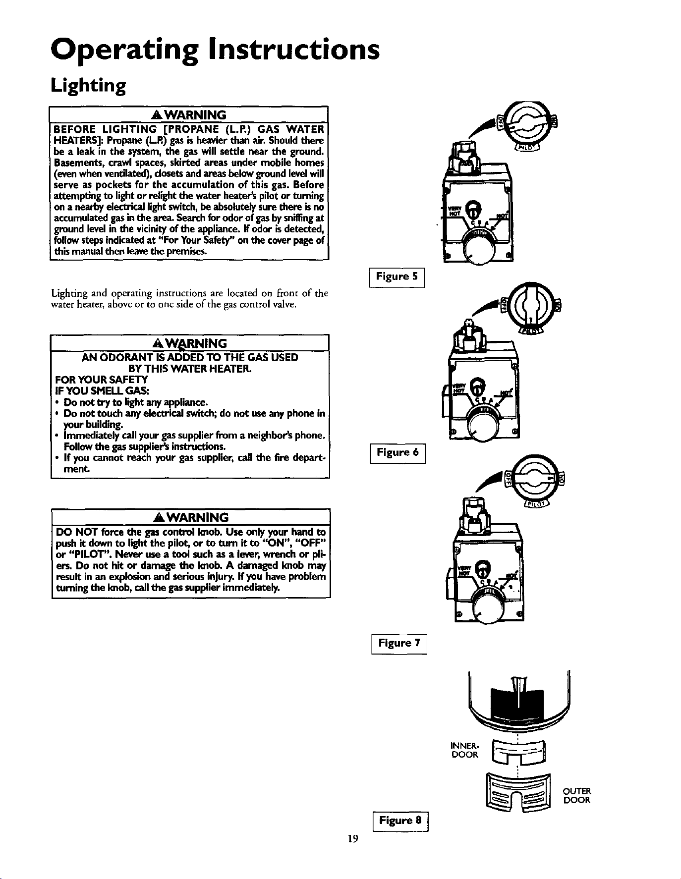
Lighting
A WARNING
BEFORE LIGHTING [PROPANE (L.R) GAS WATER
HEATERS]:Propane(I-R) gasis heavierthanair. Shouldthere
be a leak in the system,the gaswill settle near the ground.
Basements,crawlspaces,skirted areasunder mobile homes
(evenwhenventilated),closetsandareasbelow groundlevelwill
serve as pocketsfor the accumulation of this gas. Before
attemp_ngto lightor rellghtthewater heater'spilotor turning
on a nearbyelectricallightswitch,beabsolutelysurethereisno
accumulatedgasinthearea.Searchforodorof gasbysnifEngat
groundlevelinthe vicinityofthe appliance.If odor is detected,
follow stepsindicatedat "For YourSafety"onthe coverpageof
this manualthen leavethe premises.
Lighting and operating instructions are located on front of the
water heater, above or to one side of the gas control valve.
Figure 5 ]
_,W_,RNING
AN ODORANT IS ADDED TO THE GAS USED
BYTHIS WATER HEATER.
FORYOUR SAFETY
IFYOU SMELLGAS:
Do nottry to lightanyappliance.
Do not touch anyelect_cal switch;do not useanyphonein
yourbuilding.
Immediatelycallyourgassupplierfrom a neighbor'sphone.
Followthe gassuppliersinstructions.
If you cannotreachyour gassupplier,call the fire depart.
ment.
l Figure 6 1
_,WARNING
DO NOT force the gascontrol knob, Use only your hand to
pushit downto lightthe pilot, or to turn it to "ON", "OFF"
or "PILOT". Never usea tool suchasa lever,wrench or pli-
er_ Do not hit or damage_.e knob,A damagedknob may
resultin an explosionandsenous injury.If you haveproblem
turningthe Imob,callthe gassupplier immediately.
Figure 7 ]
19
Figure 8 ]
INNER-
DOOR
i
OUTER
DOOR
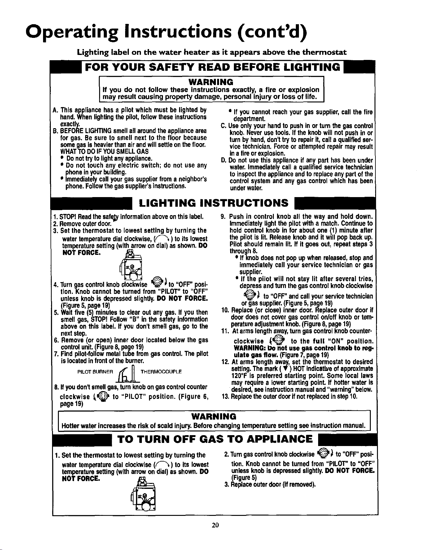
Operating Instructions (cont'd)
Lighting label on the water heater as it appears above the thermostat
FOR YOUR SAFETY READ BEFORE LIGHTING
WARNING I
If you do not follow these instructions exactly, a fire or explosion
may resu t caus ng property damage, persona njury or oss of fe.
A. This appliancehas a pilotwhichmust be lighted by
hand.Whenlightingthe pilot,followtheseinstructions
exactly.
B, BEFORELIGHTINGsmellall aroundthe applianceares
for gas. Be sure to smell next to the floor because
somegas isheavierthanairandwillsettleonthe floor.
WHATTODOIFYOUSMELLGAS
• Donottryto lightanyappliance.
• Do not touch any electric switch;do not use any
phoneinyourbuilding.
• Immediatelycallyourgas supplierfroma neighbor's
phone. Followthegas supplier'sinstructions.
C,
D,
• If youcannot reachyour gas supplier,call the fire
department.
Useonlyyourhandto pushinor turn the gas control
knob.Neverusetools.If the knobwill not pushin or
turn byhand,don'ttryto repairit, calla qualifiedeer-
vicetechnician.Forceor attemptedrepairmay result
ina fireorexplosion.
Do not use this applianceif any psrt has beenunder
water.Immediatelycall a qualifiedservicetechnician
to inspecttheapplianceandto replaceanypartofthe
controlsystemandany gas controlwhich has been
underwater.
LIGHTING INSTRUCTIONS
1.STOP!Readthe safe_ informationaboveonthislabel.
2.Removeouterdoor.
3. Set thethermostat to lowest setting by turning the
watertemperaturedial clockwise,(r-,_) to itslowest
temperaturesetting(witharrowondial) asshown.DO
NOT FORCE.
4. TurngascontrolknobclockwiseV to "OFF" posi-
tion. Knob cannot be turned from "PILOT" to "OFF"
unlessknob is depressedslightly.DO NOT FORCE.
(Figure5, page19)
i. Waitfive (5) minutesto clearout any gas. If youthen
smellgas, STOP!Follow"B" in the safetyinformation
aboveon this label.If you don'tsmell gas, go to the
nextstep.
Remove(or open)inner door locatedbelowthe gas
control unit.(Figure8, page19)
7. Findpilot-followmetaltube fromgas control.The pilot
islocatedinfrontofthe burner.
PILOT BURNER f_ THERMOCOUPLE
8. Ifyoudon'tsmellgas,turn knobongascontrolcounter
clockwise {,@ to "PILOT" position. (Figure 6,
pagef9)
9. Push in control knob all the way and hold down.
Immediatelylightthe pilotwitha match.Continueto
hold control knob in for about one (1) minute after
thepilot is lit.Releaseknoband it willpop back up.
Pilotshouldremainlit. If it goesout, repeat steps 3
through8,
• If knobdoesnotpop up whenreleased,stopand
immediatelycall your servicetechnicianor gas
supplier.
e If the pilot will not stay lit after several tries
depressandturnthe gas controlknobclockwise
ef_.J to "OFF" andcallyourservicetechnician
orgassupplier.(Figure5, page19)
10. Replace(or close)innerdoor.Replaceouterdoor if
doordoesnot covergascontrolon/offknob ortem-
peratureadjustmentknob.(Figure8, page19)
11. At armslengthaway,turn gascontrolknobcounter-
clockwise _ to the full "ON" position.
WARNING: bo not use gas control knob to reg.
ulate gas flow. (Figure7, page19)
12. At armslengthaway,set the thermostatto desired
setting.The mark( • ) HOTindicatLveofapproximate
120°F is preferredstarting point. Some local laws
may requirea lowerstartingpoint.If hotter water is
desired,seeinstructionmanualand"warning" below.
13.Replacetheouterdoorifnotreplacedinstep10.
I WARNING
Hotter waterincreasesthe riskof scald injury.Beforechangingtemperaturesetting see instructionmanual.
TO TURN OFF GAS TO APPLIANCE
1o
Set the thermostatto lowest settingbyturning the
watertemperaturedial clockwise(r.,_) to its lowest
temperaturesetting(witharrowon dial)as shown.DO
NOT FORCE.
2.Turngascontrolknob clockwise_V _ to "OFF" posi-
tion. Knobcannotbeturnedfrom"PILOT" to "OFF"
unlessknob is depressedslightly.DO NOT FORCE,
(Figure5)
3. Replaceouterdoor(if removed).
2O
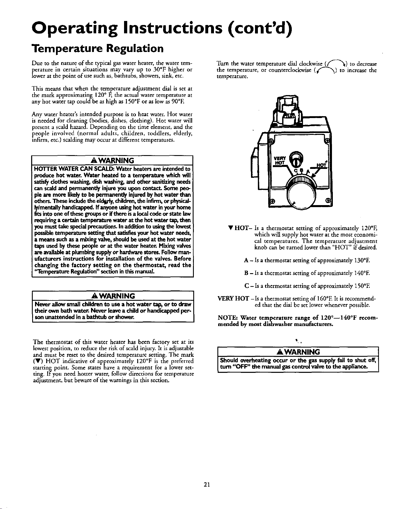
Operating Instructions (cont'd)
Temperature Regulation
Due to the nature of the typical gas water heater, the water tem-
erature in certain situations may vary up to 30°F higher or
_o_werat the point of use such as, bathtubs, showers, sink, etc.
Turn the water temperature dial dockwise_f_-"_) to decrease
the temperature, or counterclockwise (_"-_'_) to increase the
temperature.
This means that when the temperature adjustment dial is set at
the mark approximating 120 ° F, the actual water temperature at
any hot water tap could be as high as 1500F or as low as 90°E
Any water heater's intended purpose is to heat water. Hot water
is needed for cleaning (bodies, dishes, clothing). Hot water will
present a scald hazard. Depending on the time element, and the
people involved (normaladults, children, toddlers, elderly,
infirm, etc.) scalding may occur at different temperatures.
AWARNING
HOTTERWATERCAN SCALD:Water heatersare intendedto
producehot water.Water heatedto a temperature whichwill
satisfyclotheswashing,dishwashing,andother sanitizingneeds
canscaldand permanently injureyouuponcontact.Somepeo-
plearemore likelyto be permanentlyinjured_ bet waterthan
others.Theseindudethe eld_trly, children,the infirm, or physical-
ly/mentally handicapped.Ifanyoneusinghotwater inyourhome
fitsinto oneofthesegroupsor ifthereisalocalcedeor statelaw
requiring acertaintemperaturewater atthe hotwater tap,then
youmusttakespecialprecautions.In.additionto usingthe lowest
possibletemperaturesettingthat satisfiesyour hotwater needs,
a meanssuchasa mixingvalve,shouldbe usedat the hotwater
tapsusedbythese peopleor at the water heator.Mixingvalves
areavailableat plumbingsupplyor hardwarestores.Followman-
ufacturersinstructionsfor installation of the valves.Before
changingthe factory setting on the thermostat, read the
'q'emperatureRegulation"sectioninthis manual.
i
• HOT- Is a thermostat setting of approximately 120°F,
which will supply hot water at the most economi-
cal temperatures. The temperature adjustment
knob can be turned lower than "HOT" if desired.
A - Is a thermostat setting of approximately 130°E
B - Is a thermostat setting of approximately ] 40°E
A, WARNING
Never allowsmallchildrento usea hot water _ or to draw
theirown bathwater. Never leavea childor handicappedper-
sonunattendedina bathtubor shower.
C -Is a thermostat setting of approximately 150°E
VERY HOT -Is a thermostat setting of 160°E It is recommend-
ed that the dial be set lower whenever possible.
NOTE: Water temperature range of 120°--140°F recom-
mended by most dishwasher manufacturers.
The thermostat of this water heater has been factory set at its
lowest position, to reduce the risk of scald injury. It is adjustable
and must be reset to the desired temperature setting. The mark
(•) HOT indicative of approximately 120°F is the preferred
starting point. Some states have a requirement for a lower set-
ting. If you need hotter water, follow directions for temperature
adjustment, but beware of the warnings in this section.
AWARNING
Shouldoverheatingoccuror the gassupplyfail to shut off,
tom "OFF" the manualgascontrolvalveto _e appliance.
21
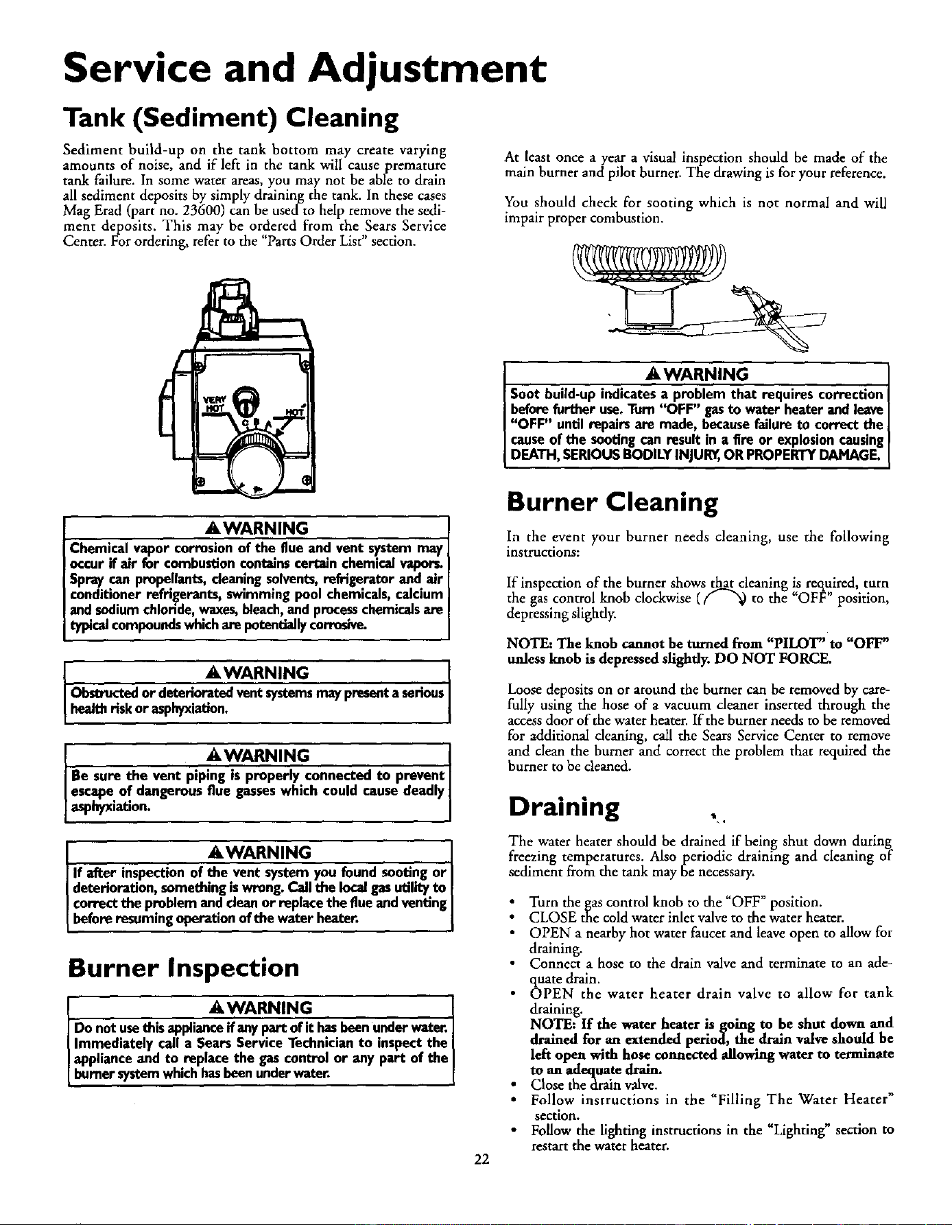
Service and Adjustment
Tank (Sediment) Cleaning
Sediment build-up on the tank bottom may create varying
amounts of noise, and if left in the tank will cause premature
tank failure. In some water areas, you may not be able to drain
all sediment deposits by simply draining the tank. In these cases
Mag Erad (part no. 23600) can be used to help remove the sedi-
ment deposits. This may be ordered from the Sears Service
Center. For ordering, refer to the "Parts Order List" section.
At least once a year a visual inspection should be made of the
main burner and pilot burner. The drawing is for your reference.
You should check for sooting which is not normal and will
impair proper combustion.
AWARNING
Chemical vapor corrosionof the flue and vent systemmay
occurif air for combustioncontainscertain chemicalvapors.
Spray canpropellants,cleaningsolvents,refrigerator and air
conditionerrefrigerants, swimmingpool chemicals,calcium
andsodiumchloride,waxes,bleach,and processchemicalsare
typicalcompoundswhichare potentiallycorrosive.
AWARNING
Obstructedor deterioratedventsystemsmaypresentaserious
healthrisk or asphyxiation.
AWARNING I
Be sure the vent piping is properly connected to prevent I
escapeof dangerousflue gasseswhich could causedeadly
asphyx ation. [
•,WARNING I
If after inspectionof the vent system you found sooting or I
deterioration,something iswrong. Call the localgasutilityto
correctthe problemand cleanor replace the flueand venting
beforeresumngoperat onof the water heater. {
Burner Inspection
. AWARNING
Do not usethisapplianc_ hasbeenunderwater,
Immediately call a Sears Service Technicianto inspectthe
appliance and to replace the gascontrol or any part of the
burnersystemwhich hasbeenunderwater.
22
AWARNING ]
Soot build-up indicatesa problem that requires correction
beforefurther use.Turn "OFF" gasto water heaterand leave
"OFF" until repairs are made,becausefailureto correctthe
causeof the sootingcan result in a fire or explosioncausing
DEATH,SEROUS BODILYINJUR_,OR PROPERTYDAMAGE.
Burner Cleaning
In the event your burner needs cleaning, use the following
instructions:
If inspection of the burner shows that cleaning is required, turn
the gas control knob clockwise (_ to the "OFF" position,
depressing slightly.
NOTE: The knob cannot be turned from "PILOT" to "OFF"
unless knob is depressed slighdy. DO NOT FORCE.
Loose deposits on or around the burner can be removed by care-
fully using the hose of a vacuum cleaner inserted through the
access door of the water heater. If the burner needs to be removed
for additional cleaning, call the Sears Service Center to remove
and clean the burner and correct the problem that required the
burner to be cleaned.
Draining ,
The water heater should be drained if being shut down during
freezing temperatures. Also periodic draining and cleaning of
sediment from the tank may be necessary.
Turn the gas control knob to the _OFF" position.
CLOSE the cold water inlet valve to the water heater.
• OPEN a nearby hot water faucet and leave open to allow for
draining.
• Connect a hose to the drain valve and terminate to an ade-
quate drain.
• OPEN the water heater drain valve to allow for tank
draining.
NOTE: If the water heater is going to be shut down and
drained for an extended period, the drain valve should be
left open with hose connected allowing water to terminate
to an adequate drain.
• Close thedrain salve.
• Follow instructions in the "Filling The Water Heater"
section.
Follow the lighting instructions in the "Lighting" section to
restart the water heater.
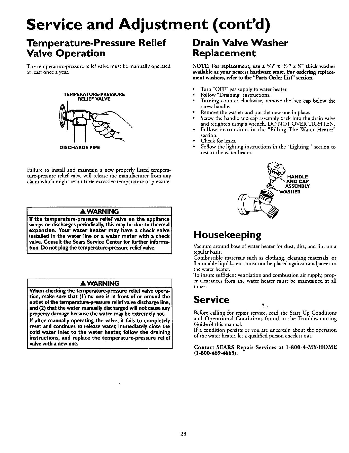
Service and Adjustment (cont'd)
Temperature-Pressure Relief
Valve Operation
Drain Valve Washer
Replacement
The temperature-pressure relief valve must be manually operated
at least once a year.
NOTE: For replacement, use a '_" x '_/_" x ¼" thick washer
available at your nearest hardware store. For ordering replace-
ment washers, refer to the "Parts Order List" section.
TEMPERATURE-PRESSURE
RELIEF VALVE
DISCHARGE PIPE
Turn "OFF" gas supply to water heater.
Follow _Draining" instructions.
• Turning counter clockwise, remove the hex cap below the
screw handle.
Remove the washer and put the new one in place.
Screw the handle and cap assembly back into the drain valve
and retighten using a wrench. DO NOT OVER TIGHTEN.
Follow instructions in the "Filling The Water Heater"
section.
Check for leaks.
Follow the lighting instructions in the "Lighting " section to
restart the water heater.
Failure to install and maintain a new properly listed tempera-
ture-pressure relief valve will release the manufacturer from any
claim which might result from excessive temperature or pressure.
AWARNING
If the temperature-pressure relief valve on the appliance
weepsor dischargesperiodically,thismay be dueto thermal
expansion. Your water heater may have a check valve
installedin the water line or a water meter with a check
valve.Consultthe SearsServiceCenter for further informa-
tion. Do not plugthe temperature-pressurerelief valve.
_WARNING
When checkingthe tempereture-pressurerelief valve opera-
don, make sure that (I) no one is in front of or aroundthe
outlet of the temperature-pressure reliefvalvedischargeline,
and(2) that the water manuallydischargedwill not causeany
propertydamagebecausethe water maybe extremelyhot.
If after manually operating the valve, it failsto completely
reset and continuesto release water, immediately closethe
cold water inlet to the water heater, follow the draining
instructions, and replace the temperature-pressure relief
valvewith a newone.
ASSEMBLY
Housekeeping
Vacuum around base of water heater for dust, dirt, and lint on a
regular basis.
Combustible materials such as clothing, cleaning materials, or
flammable liquids, etc. must not be placed against or adjacent to
the water heater.
To insure sufficient ventilation and combustion air supply, prop-
er clearances from the water heater must be maintained at all
times.
Service
Before calling for repair service, read the Start Up Conditions
and Operational Conditions found in the Troubleshooting
Guide of this manual.
If a condition persists or you are uncertain about the operation
of the water heater, let a qualified person check it out.
Contact SEARS Repair Services at 1-800-4-MY-HOME
(1-800-469-4663).
23
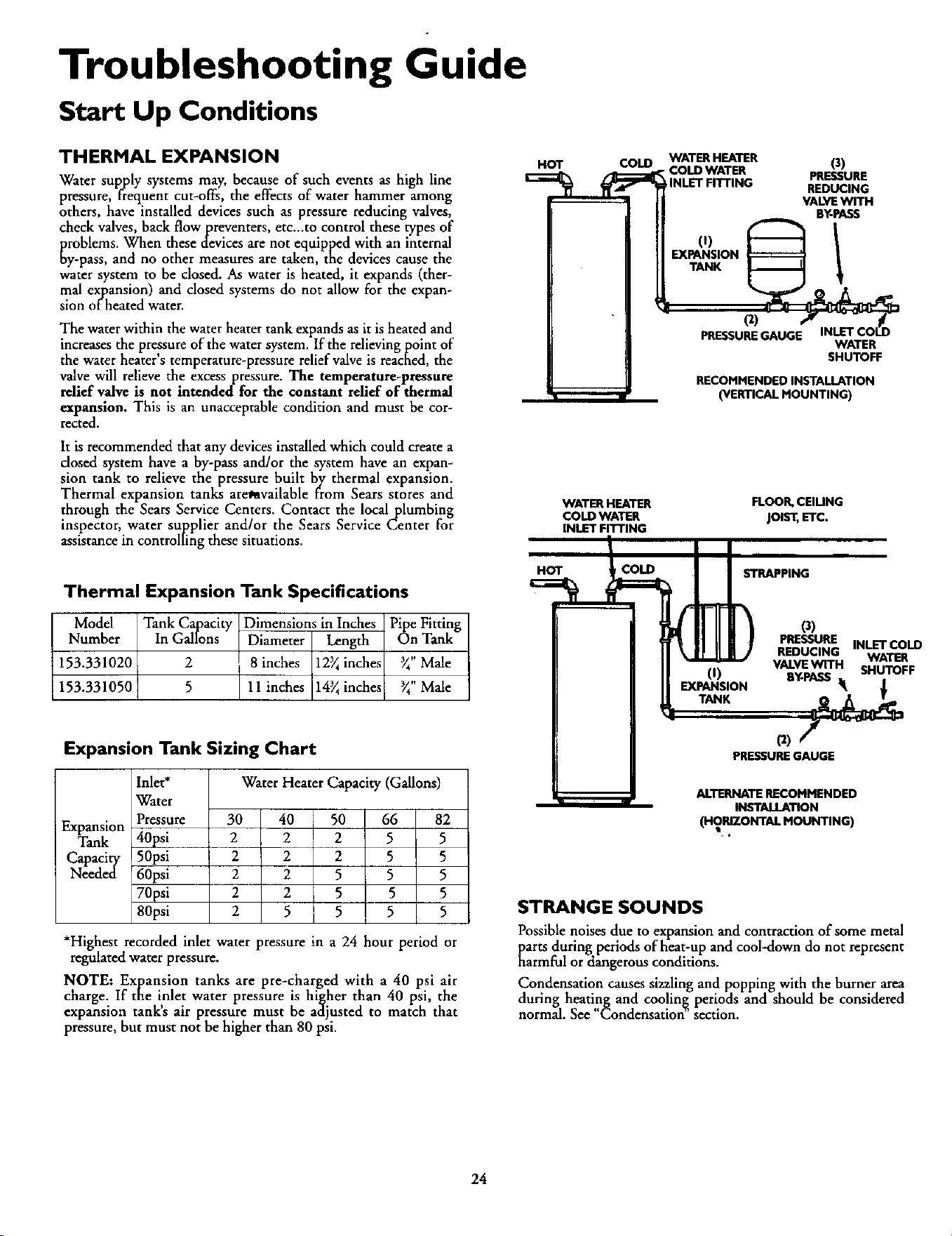
Troubleshooting Guide
Start Up Conditions
THERMAL EXPANSION
Water supply systems may, because of such events as high line
pressure, frequent cut-offs, the effects of water hammer among
others, have installed devices such as pressure reducing valves,
check valves, back flowpreventers, etc_.to control these types of
problems. When these devices are not equipped with an internal
by-pass, and no other measures are taken, the devices cause the
water system to be closed. As water is heated, it expands (ther-
mal expansion) and closed systems do not allow for the expan-
sion of heated water.
The water within the water heatertank expands as it is heated and
increases the pressure of the water system. If the relieving point of
the water heater's temperature-pressure relief valve is reached, the
valve will relieve the excess pressure. The temperature-pressure
relief valve is not intended for the constant relief of thermal
expansion. This is an unacceptable condition and must be cor-
rected.
It is recommended that any devices installed which could create a
closed system have a by-pass and/or the system have an expan-
sion tank to relieve the pressure built by thermal expansion.
Thermal expansion tanks are_vailable from Sears stores and
through the Sears Service Centers. Contact the local plumbing
inspector, water supplier and/or the Sears Service Center for
assistance in controlling these situations.
Thermal Expansion Tank Specifications
Model Tank Capacity Dimensions in Inches Pipe Fitting
Number In Gallons Diameter Length On Tank
153.331020 2 8 inches 12_ inches _" Male
153.331050 5 11 inches 14_ inches _" Male
HOT
COLD
HOT
WATER HEATER
COLD WATER
INLET FITTING
WATERHEATER
COLDWATER
INLETFII-rlNG
0)
TANK
(3)
PRESSURE
REDUCING
VALVEWITH
BY-PASS
o)
PRESSUREGAUGE
WATER
SHUTOFF
RECOMMENDED INSTALLATION
(VERTICAL MOUNTING)
FLOOR, CEILING
JOIST,ETC.
STRAPPING
0)
PRESSURE INLETCOLD
REDUCING WATER
VALVEWITH SHUTOFF
(1) BY-I_SS
EXPANSION _
Expansion Tank Sizing Chart
Expansion
Tank
Capacity
Needed
Inlet*
Water
Pressure
40psi
50psi
60psi
70psi
80psi
Water Heater Capacity (Gallons)
30 40 50 66 82
2 2 2 5 5
2 2 2 5 5
2 2 5 5 5
2 2 5 5 5
2 5 5 5 5
*Highest recorded inlet water pressure in a 24 hour period or
regulated water pressure.
NOTE: Expansion tanks are pre-charged with a 40 psi air
charge. If the inlet water pressure is higher than 40 psi, the
expansion tank's air pressure must be adjusted to match that
pressure, but must not be higher than 80 psi.
0)
PRESSUREGAUGE
ALTERNATE RECOMMENDED
INSTALLATION
(HORIZONTAL MOUNTING)
STRANGE SOUNDS
Possible noises due to expansion and contraction of some metal
parts during periods of heat-up and cool-down do not represent
harmful or dangerous conditions.
Condensation causes sizzling and popping with the burner area
during heating and cooling periods and should be considered
normal. See "Condensation" section.
24
Troubleshooting Guide (cont'd)
Start Up Conditions (cont'd)
CONDENSATION
Whenever the water heater is filled with cold water, a certain
amount of condensation will form while the burner is on. A
water heater may appear to be leakingwhen in fact the water is
condensation. This usually happens when:
• When a new water heater is filled with cold water for the
first time.
• When gas burns and water vapor isproduced in water
heaters, particularly high efficiency models where flue tem-
peratures are lower.
• When you use large amounts of hot water in a short time
and the refill water is very cold.
Moisture from the products of combustion condense on the
cooler tank surfaces and form drops of water which may fall
onto the burner or other hot surfaces to produce a "sizzling" or
"frying" noise.
Excessive condensation can cause pilot outage due to water run-
ning down the flue tube onto the main burner and putting out
the pilot.
Because of the suddenness and amount of water, condensation
water may be diagnosed as a "tank leak". After the water in the
tank warms up (about 1-2 hours), the condition should
disappear.
SMOKE/ODOR
It is not uncommon to experience a small amount of smoke and
odor during the initial start-up. This is due to burning off of oil
from metal parts, and will disappear in a short while.
Operational Conditions
SMELLY WATER
In each glasslined water heater there is installed at least one
anode rod (see parts section) for corrosion protection of the
tank. Certain water conditions will cause a reaction between this
rod and the water. The most common complaint associated with
t e anode rod is one of a rotten egg smell . This odor Is derived
from hydrogen sulfide gas dissolved in the water. The smell is
the result orfour factors which must all be present for the odor
to develop:
a. a concentration of sulfate in the supply water.
b. little or no dissolved oxygen in the water.
c. a sulfate reducing bacteria within the water heater. (This
harmless bacteria is non-toxic to humans.)
d. an excess of active hydrogen in the tank. This is caused by
the corrosion protective action of the anode.
Do not assume the water heater is leaking until there has been
enough time for the water in the tank to warm up.
An undersized water heater will cause more condensation. The
water heater must be sized properly to meet the family's
demands for hot water including dishwashers, washing machines
and shower heads.
Excessive condensation may be noticed during the winter and
early spring months when incoming water temperatures are at
their lowest.
Smelly water may be eliminated or reduced in some water heater
models by replacing the anode(s) with one of less active material,
and then chlorinating the water heater tank and all hot water
lines. Contact Sears Service for fiarther information concerning
an Anode Replacement Kit #9001453 and this Chlorination
Treatment.
If the smelly water persists after the anode replacement and chlo-
rination treatment, we can only suggest that continuous chlori-
nation and filtering conditioning equipment be considered to
eliminate the water problem.
Good venting is essential for a gas fired water heater to operate
properly as well as to carry away products of combustion and
water vapor.
Do not remove the anode leaving the tank unprotected. By
doing so, all warranty on the water heater tank is voided.
_,WARNING
HOTTERWATERCAN SCALD:Water heatersare intendedto
producehot water.Water heatedto a temperature whichwill
satisfyclotheswashin_dishwashing,andother sanitizingneeds
canscaldandpermanentlyinjureyouuponcontact.Somepeo-
plearemorelikelyto be permanentlyinjuredbyhotwater than
others.Theseincludetheelderly,children,the infirm,orphysical-
lylmentailyhandicapped.If anyoneusinghotwater inyour home
fitsintooneofthesegroupsor ifthere isa localcodeor statelaw
requiringacertaintemperaturewaterat the hotwater ta_ then
mumusttakespecialprecautions.Inadditionto usingthe lowest
)ossibletemperaturesettingthat satisfiesyour hotwater needs,
t meanssuchasa mixingvalve,shouldbe usedat the hotwater
tapsusedby thesepeopleor at thewater heater.Mixingvalves
areavailableat plumbingsupplyor hardwarestore_Followman-
ufacturersinstructionsfor installationof the valves.Before
changingthe factory setting on the thermostat, read the
'q'emperatureRegulation"sectioninthis manual.
"AIR" IN HOT WATER FAUCETS
AWARNING
HYDROGEN GAS:Hydrogengascan be producedin a hot
watersystemthat hasnotbeenusedfora longperiod of time
(generallytwo weeksor more). Hydrogengas is extremely
flammableand explosive. To prevent the possibilityof injury
underthese conditions,we recommendthe hot water faucet
be ope.nod for severalminutesat the kitchensinkbefore any
electricalapplianceswhichare connectedto the hotwater sys-
tem are used(suchas a dishwasheror washingmachine).If
hydrogengasis present,there wdl probablybe an unusual
soundsimilarto air escapingthrough the pipeasthe hot water
faucetis opened.There must be no smokingor open flame
nearthefaucetat the time it isopen.
25
Troubleshooting Guide (cont'd)
HIGH TEMPERATURE SHUT OFF SYSTEM WATER IS TOO HOT
This water heater is equipped with an automatic gas shut off sys-
tem. The high temperature shut off is built into the gas control
valve. This system shuts off the gas supply to the water heater
burners when high water temperatures are present. It is non-
resettable. If the high temperature shut off activates, the gas con-
trol valve must be replaced. If this were to occur, turn "OFF" the
entire gas supply to the water heater. Contact the Sears Service
Center.
• The temperature adjustment dial may be set too high. See the
Temperature Adjustment section.
NOTE: A period of time is necessary after an adjustment
has been made for the water temperature to reach the new
temperature setting.
• If lower temperature settings will not lower the water tempera-
ture, call the Sears Service Center.
AWARNING I
Shouldoverheatingoccuror the gassupplyfail to shutoff,
turn "OFF" the manual gascontrol valve to the appliance.
NOT ENOUGH OR NO HOT WATER
• Check the manual gas shut offvalve to be sure it is open.
• Check the pilot flame. It may have gone out. All models have
an opening behind the outer door for view,,ingthe pilot.
If the pilot is not lit, follow _ Lighting instructions in this
manual or located above the gas control valve on the water
heater to relight the pilot. If the water was extremely hot and is
now cold, the high limit safety temperature shut off may have
put out the burner and pilot. If the high temperature shut off
activates, the gas controlvalve must be replaced. Contact the
Sears Service Center.
_ The gas control knob must be turned to the "ON"position.
The temperature adjustment dial may be set too low. See the
Temperature Regulation section.
The gas company can check the gas input to see if it is correct.
An underfired water heater will not heat water as quickly.
• Look for leaking or open hot water faucets. Make sure all are
dosed.
• The cold water inlet temperature may be colder during the
winter months. It will take longer to heat the water and seem
like less hot water.
• If you cannot find what is wrong, call the Sears Service
Center.
A WARNING
Due to the nature of the typical gas water heater, the
water temperature in certain situations may be hotter
than the thermostat setting.
Short, frequent draws of hot water - especiallywith very
coldincomingwater - can shockthe thermostat into brief
operation resulting in hotter and hotter layersof water
closerto the top of the tank.
Changes in hot water usagepatterns or raisingthe tem-
perature differential between the cut-on of the thermo-
stat and the cold water temperature will usuallyeliminate
the problem.
26
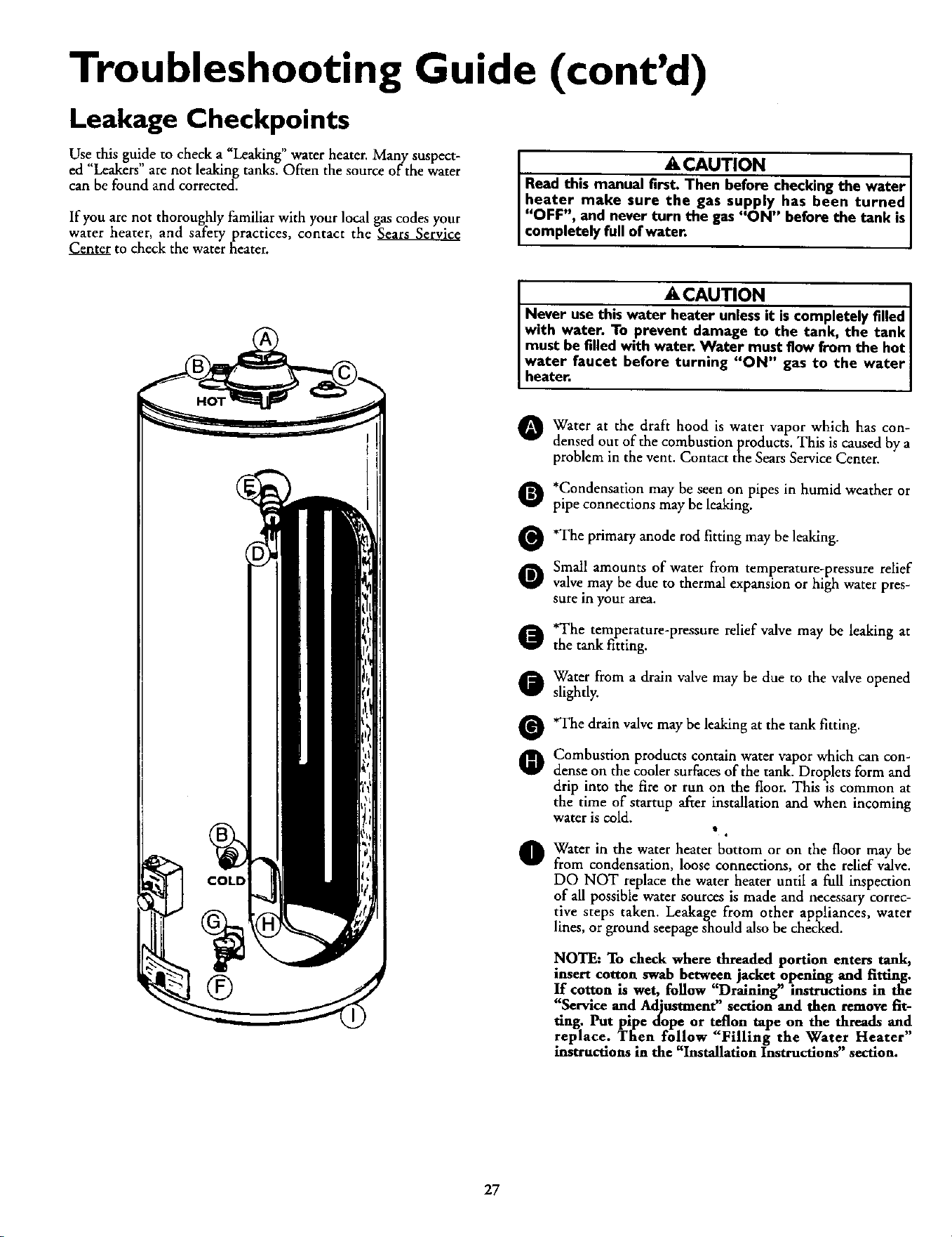
Troubleshooting Guide (cont'd)
Leakage Checkpoints
Use this guide to check a "Leaking" water heater. Many suspect-
ed "Leakers" are not leaking tanks. Often the source of the water
can be found and corrected.
If you are not thoroughly familiar with your local gas codes your
water heater, and safety practices, contact the Sears
_enter to check the water heater.
• _, CAUTION . [
Read this manual first. Then before checking the water I
heater make sure the gas supply has been turned J
"OFF", and never turn the gas "ON" before the tank is
complete y fu of water.
A CAUTION. J
Never use this water beater unless it is completely filled J
with water. To prevent damage to the tank, the tank J
must be filled with water. Water must flow from the hot
water faucet before turning "ON" gas to the water
heater.
O Water at the draft hood is water which hasvapor
con-
densed out of the combustion products. This is caused by a
problem in the vent. Contact the Sears Service Center.
O *Condensation may be seen on pipes in humid weather or
pipe connections may be leaking.
Q'The primary anode rod fitting may be leaking.
Small amounts of water from temperature-pressure relief
O valve, may be due to thermal expansion or high water pres-
sure In your area.
Q'The temperature-pressure relief valve may be leaking at
the tank fitting.
Q Water from a drain valve may be due to the valve opened
slightly.
Q'The drain valve may be leaking at the tank fitting.
Q Combustion products contain water vapor which can con-
dense on the cooler surfaces of the tank. Droplets form and
drip into the fire or run on the floor. This is common at
the time of startup after installation and when incoming
water is cold.
,
O Water in the water heater bottom or on the floor be
may
from condensation, loose connections, or the relief valve.
DO NOT replace the water heater until a full inspection
of all possible water sources is made and necessary correc-
tive steps taken. Leakage from other appliances, water
lines, or ground seepage should also be checked.
NOTE: To check where threaded portion enters tank,
insert cotton swab between jacket opening and fitting.
If cotton is wet, follow "Draining" instructions in the
"Service and Adjustment" section and then remove fit-
ring. Put pipe dope or teflon tape on the threads and
replace. Then follow "Filling the Water Heater"
instructions in the "Installation Instructions" section.
27
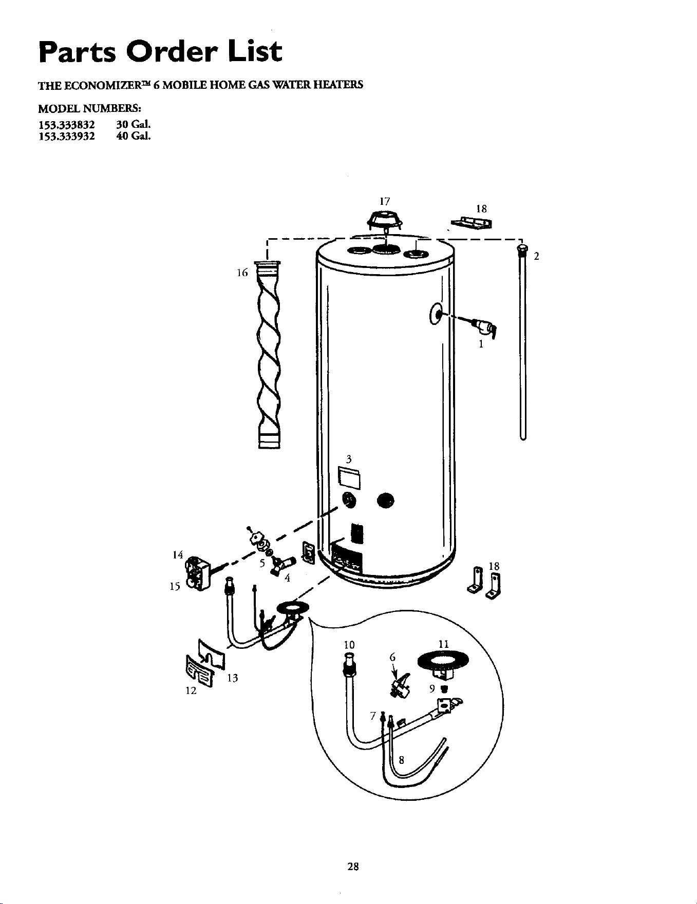
Parts Order List
THE ECONOMIZERm6MOBILEHOMEGASWATERHEATERS
MODEL NUMBERS:
153.333832 30Gal.
153.333932 40Gal.
16
17
18
12
13
28
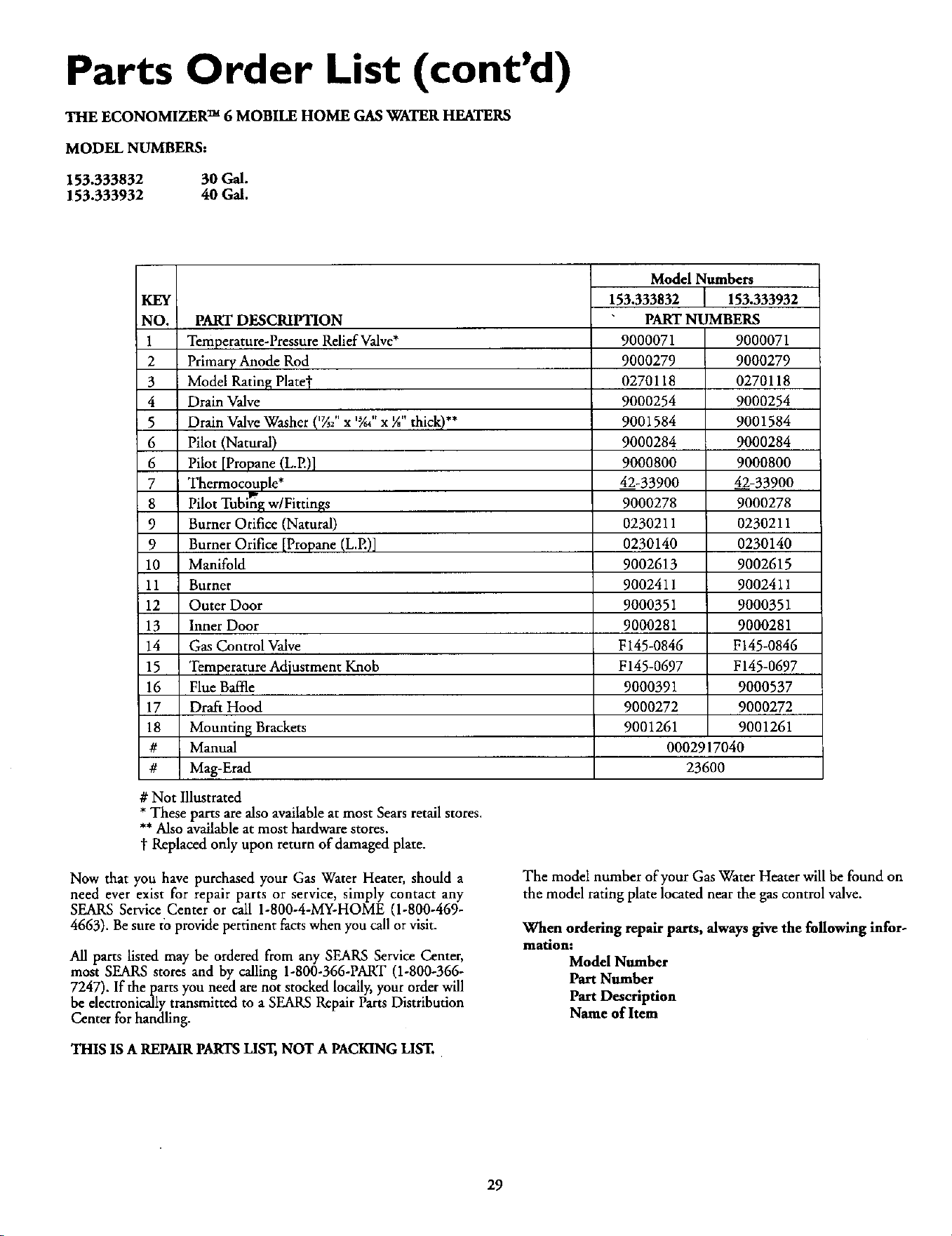
Parts Order List (cont'd)
THE ECONOMIZERm6MOBILEHOMEGASWATERHEATERS
MODEL NUMBERS:
153.333832 30Gal.
153.333932 40G_,
KEY
NO. PARTDESCRIPTION
1 Temperature-Pressure Relief Valve*
2 Primary Anode Rod
3 Model Rating Platey
4 Drain Valve
5 Drain Valve Washer ('_2" x 'Vd' x 7." thick)**
6 Pilot (Natural)
6 Pilot [Propane (L,P..)]
7 Thermocouple*
8 Pilot Tubing w/Fittings
9 Burner Orifice (Natural)
9 Burner Orifice [Propane (L.E)]
10 Manifold
11 Burner
12 Outer Door
13 Inner Door
14 Gas Control Valve
15 Temperature Adjustment Knob
16 Flue Baffle
17 Draft Hood
18 Mounting Brackets
# Manual
# Mag-Erad
9000071
9000279
0270118
9OOO254
9001584
9000284
9000800
42-33900
9000278
0230211
0230140
9002613
9002411
9000351
9000281
F145-0846
F145-0697
9000391
9000272
9001261
Model Numbers
153.333832 153.333932
PART NUMBERS
9000071
9000279
0270118
9000254
9001584
9000284
9000800
4_2-33900
9000278
0230211
0230140
9002615
9002411
9000351
9000281
F145-0846
F145-0697
9000537
9000272
9001261
0002917040
23600
# Not Illustrated
* These parts are also available at most Sears retail stores.
** Also available at most hardware stores.
t Replaced only upon return of damaged plate.
Now that you have purchased your Gas Water Heater, should a
need ever exist for repair parts or service, simply contact any
SEARS Service Center or call 1-800-4-MY-HOME (1-800-469-
4663). Be sure to provide pertinent facts when you call or visit.
All parts listed may be ordered from any SEARS Service Center,
most SEARS stores and by calling 1-800-366-PART (1-800-366-
7247). If the parts you need are not stocked locally, your order will
be electronically transmitted to a SEARS Repair Parts Distribution
Center for handling.
The model number of your Gas Water Heater will be found on
the model rating plate located near the gas control valve.
When ordering repair parts, always give the following infor-
mation:
Model Nmnber
Part Number
Part Descripdon
Name of Item
THIS IS A REPAIR PARTSLIST,NOT A PACKING LIST.
29

Notes
30

Notes
31
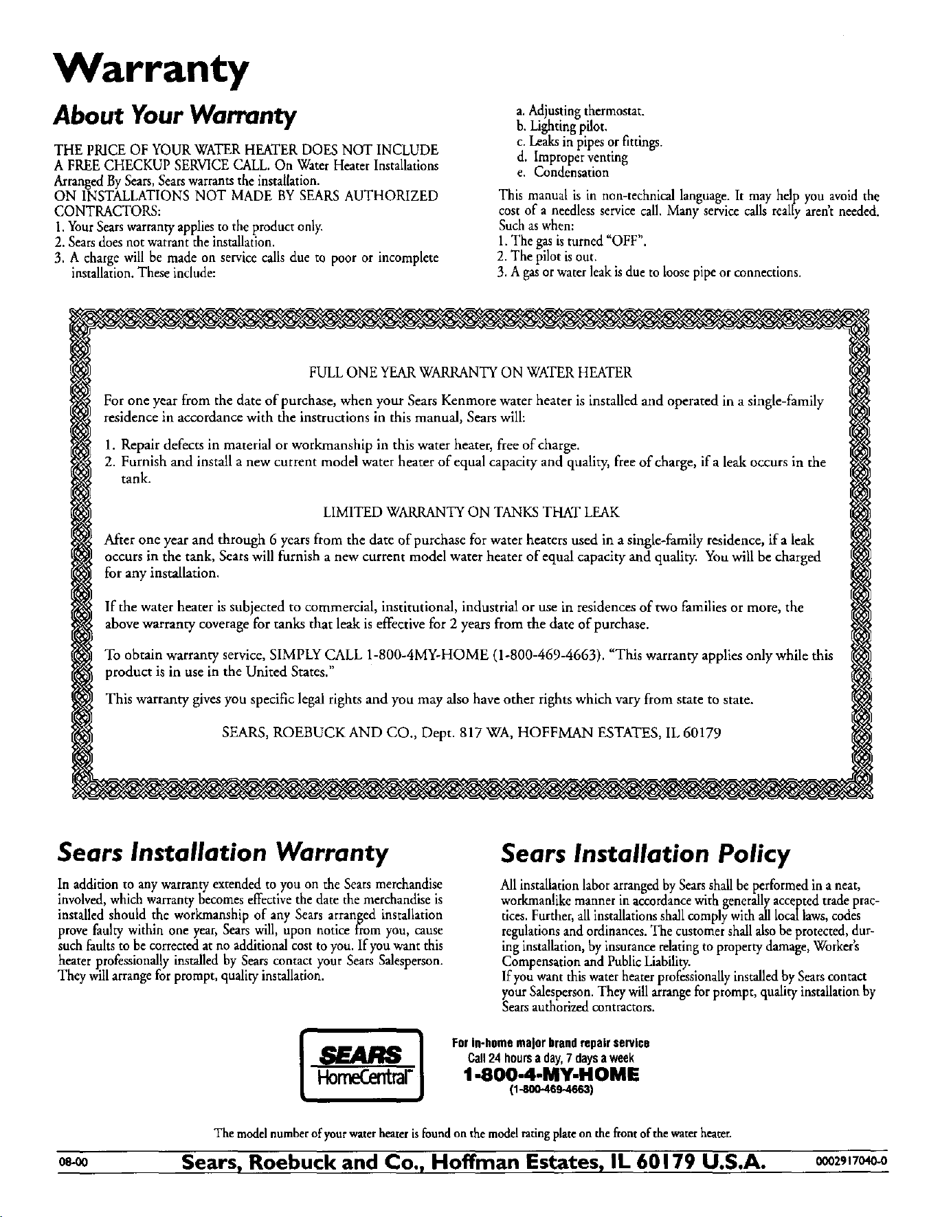
Warranty
About Your Warranty
THE PRICE OF YOUR WATER HEATER DOES NOT INCLUDE
A FREE CHECKUP SERVICE CALL. On Water Heater Installations
Arranged By Sears, Sears warrants the installation.
ON INSTALLATIONS NOT MADE BY SEARS AUTHORIZED
CONTRACTORS:
1. Your Sears warranty applies to the product only.
2. Sears does not warrant the installation.
3. A charge will be made on service calls due to poor or incomplete
installation. These include:
a. Adjustingthermostat.
b. Lightingpilot.
c. Leaksin pipesor fittings.
d. Improper venting
e. Condensation
This manual is in non-technical language.It may help you ,avoidthe
cost of a needless service call. Manyservice calls really arent needed.
Suchas when:
1.The gasis turned "OFF".
2.The pilot isout.
3.A gasor water leakisdue to loosepipe or connections.
FULL ONE YEAR WARRANTY ON WATER HEATER
For one year from the date of purchase, when your Sears Kenmore water heater is installed and operated in a single-family
residence in accordance with the instructions in this manual, Sears will:
1. Repair defects in material or workmanship in this water heater, free of charge.
2. Furnish and install a new current model water heater of equal capacity and quality, free of charge, if a leak occurs in the
tank.
LIMITED WARRANTYON TANKS THAT LEAK
After one year and through 6 years from the date of purchase for water heaters used in a single-family residence, if a leak
occurs in the tank, Sears will furnish a new current model water heater of equal capacity and quality. You will be charged
for any installation.
If the water heater is subjected to commercial, institutional, industrial or use in residences of two families or more, the
above warranty coverage for tanks that leak is effective for 2 years from the date of purchase.
To obtain warranty service, SIMPLY CALL 1-800-4MY-HOME (1-800-469-4663). "This warranty applies only while this
product is in use in the United States."
This warranty gives you specific legal rights and you may also have other rights which vary from state to state.
SEARS, ROEBUCK AND CO., Dept. 817 WA, HOFFMAN ESTATES, IL 60179
Sears Installation Warranty
In addition to any warranty extended to you on the Sears merchandise
involved, which warranty becomes effective the date the merchandise is
installed should the workmanship of any Sears arranged installation
prove faulty within one year, Sears will, upon notice from you, cause
such faults to be corrected at no additional cost to you. If you want this
heater professionally installed by Sears contact your Sears Salesperson.
They will arrange for prompt, quality installation.
Sears Installation Policy
All installationlabor arrangedby Searsshall beperformed in a neat,
workmanlikemanner in accordancewith generallyacceptedtrade prac-
tices.Further,all installationsshallcomplywith alllocal laws,codes
regulationsand ordinances.The customershallalsobe protected,dur-
ing installation,by insurancerelatingto property damage,Worker's
Compensation and PublicLiability.
lfyou want this waterheater professionallyinstalledby Searscontact
your Salesperson.They willarrangefor prompt, quality installationby
Searsauthorizedcontractors.
Forin-homemajorbrandrepairservice
Call24hoursaday,7 daysaweek
1-800,,4-MY-HOME
(1-800-469-4663)
The model number of your water heater isfound on the modd rating plate on the front of thewater heater.
Sears, Roebuck and Co., HotTman Estates, IL 60179 U.S.A.
08-00 00029170400