
Installation Instructions
Modernist Pro Range
DOP48M96D/DOP36M94D
Part No. 112158 Rev G

2 English
Contents
Before
You Begin
3
Important
Customer-Assurance Information
Important Safety Instructions
Pre-Installation Checklist
General Requirements
Location Requirements
Gas Requirements
Special Gas Requirements (gas models sold in Massachusetts)
Electrical Requirements
Installation Instructions
Read All Instructions Before Using This Manual
Appliance Symbols Used In This Manual
About the Anti-tip Device
Installation-Related Safety Instructions
Product Specifications
10
What Is Included (DOP48M96)
What Is Included (DOP36M94)
Needed Tools and Parts
Installation Requirements
13
20
20
29
30
34
34
Preparing for Installation
Installing the Burner-Control Knobs
Rangetop Assembly
Verifying Proper Operation
Removing and Reinstalling the Range
Installation Checklist
35
4
13
13
16
18
18
19
4
4
4
5
10
11
12
3
3
Before You Begin
Important
English 3
Overall design/accessories may differ with the model.
Installer
•Read this manual before installing the cooktop.
•Remove all packing material before connecting
the electric and gas supply.
•Observe all governing codes and ordinances.
•
•
Leave this manual with the owner, and write the
unit's model/serial #s inside for easy reference.
Installation of this appliance requires basic
mechanical skills.
•The owner shall see to the range's proper
installation. (The warranty does not cover
product failure due to improper installation.)
Owner
•As with any heat-generating appliance, certain safety precautions must be followed.
•Ensure your range is installed properly by a qualified installer or technician.
•Ensure the wall coverings near the range can withstand the heat generated by it.
•Cabinet storage space above the range surface should be at least 30 in. (76.2 cm).
•Keep this manual handy for personal and professional reference.
Service Technician
The electrical diagram is attached inside the burner box.
Customer-Assurance Information
I
To resolve questions and installation issues, contact your Dacor dealer or the Dacor Customer
Assurance Team. Before calling, have the range's model/serial numbers available. (See the range's
data label: Double oven – left door trim of small oven; single oven – left door trim.)
Dacor Customer Assurance:
Phone: (800) 793-0093 x2813 (USA, Canada)
Hours of Operation: Mon – Fri, 5:00 a.m. to 5:00 p.m. Pacific Time
Website: www.dacor.com/customer-care/contact-us
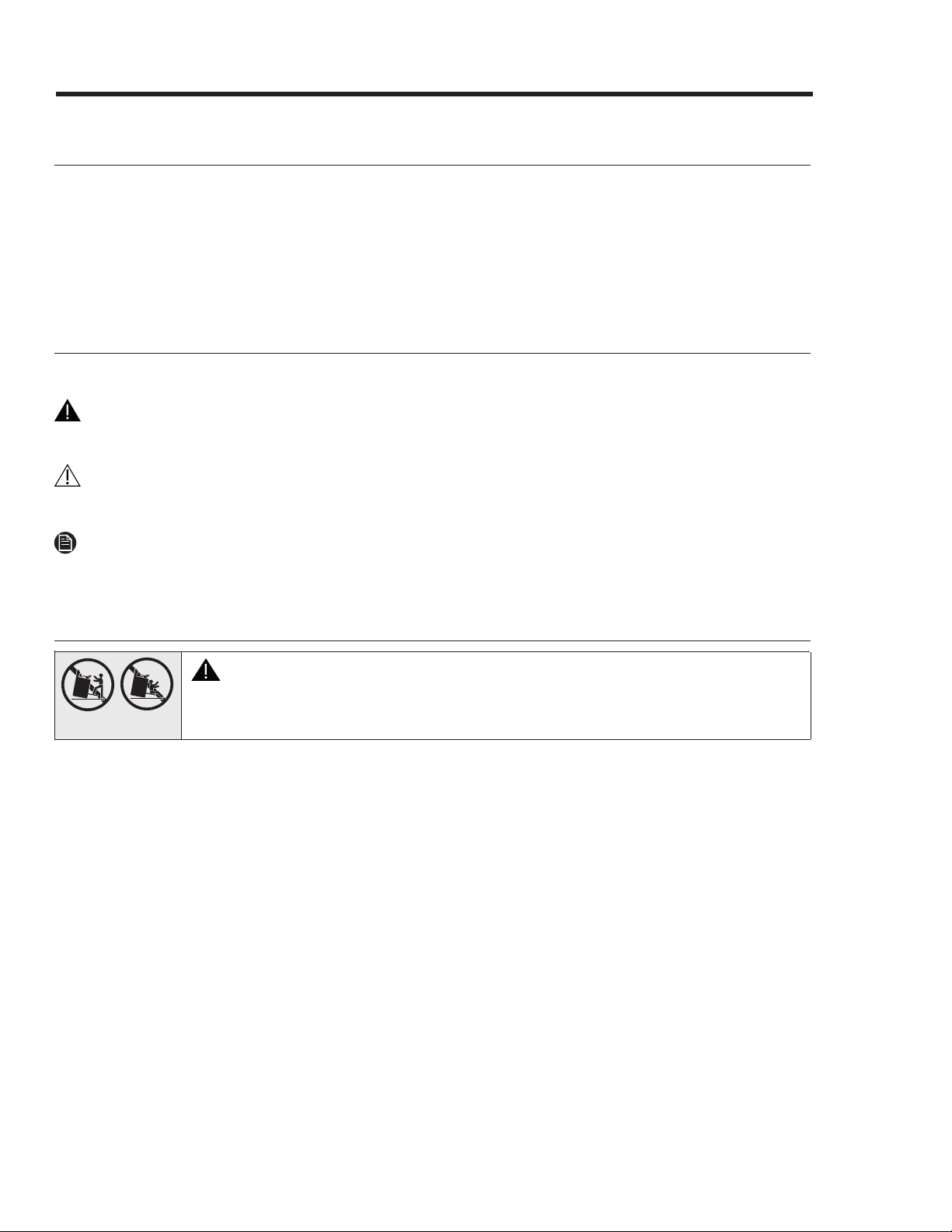
Important Safety Instructions
WARNING
All ranges can tip and cause personal injury and death. Install and check the anti-
tip bracket per the instructions and template supplied with the bracket.
•After installing the anti-tip device (see Installing the Anti-Tip Device), verify proper installation
by carefully tipping the range forward. The anti-tip device should keep the range safely in place.
•
When the range is put back in place after maintenance, be sure to re-engage the anti-tip device.
•To avoid personal/property damage, do not step/sit/lean on the range.
READ ALL INSTRUCTIONS BEFORE USING THIS APPLIANCE
•To avoid property damage/personal injury/death, follow the directions in this manual.
•Electrical and gas equipment with moving parts can be dangerous. The Important safety
instructions in this manual are intended to minimize the risk of property damage, personal
injury, and death. Read these instructions.
•Keep this manual in a handy place for reference.
Symbols Used In This Manual
These warning icons and symbols alert you to potentially unsafe conditions. Follow them explicitly.
WARNING
Hazards or unsafe practices that may result in sev
ere personal injury or death.
CAUTION
Hazards or unsafe practices that may result in electric shock, personal injury, or property damage.
NOTE
Useful tips and instructions.
About the Anti-Tip Device
State of California Proposition 65 Warning (US only)
•This product contains chemicals known to the State of California to cause cancer and birth
defects or other reproductive harm.
•Gas appliances can cause low-level exposure to Proposition 65-listed substances (e.g., carbon
monoxide, formaldehyde, soot) caused by the incomplete combustion of LP or natural gas.
Commonwealth of Massachusetts
This product must be installed by a plumber or gas fitter qualified or licensed by the State of
Massachusetts. When using ball-type gas shut-off valves, you must use the T-handle type. Multiple
flexible gas lines must not be connected in series.
4 English

Important Safety Instructions
Installation-Related Safety Instructions
English 5
• Do not touch the range during or immediately after cooking.
•Know where and how to shut off/on the range's gas-supply valve.
•Use only dry pot holders.
• Do not let children sit/stand on the range or play with any of its parts. Do not leave children
unattended near the range when it is in use.
•Remove all packaging before operating the range, and properly and immediately dispose of the
packaging.
•Keep all packaging away from children.
•Do not keep objects of interest to children on or around the range.
•Do not operate the range if it is damaged or malfunctioning, or is missing parts.
•Do not use oven cleaners/liners anywhere on the oven.
•Do not heat sealed food containers.
•Do not strike the oven glass.
•When disposing of the range, cut off the power cord, and remove the door.
•Shut off the gas, and unplug the range before service/maintenance.
•Cook meat to an internal temperature of 160 °F (71 °C) and poultry to 180 °F (82 °C).
•Air curtains or hoods that blow on the gas range shall be used only if the hood and range are
designed and tested per the Standard for Domestic Gas Ranges, ANSI Z21.1 • CSA1.1, and listed
by an independent testing lab for combination use.
•Never use the range as a space heater.
Fire Safety
•Do not store/place/use combustible items (e.g., paper, plastic, fabrics, gasoline) near the range.
•Do not wear loose-fitting or hanging garments while using the range.
•Do not let pot holders or other flammable material touch a heating element. Do not use a towel
or other bulky cloth as a pot holder.
•Do not douse a grease fire with water but turn off the burner, and smother the fire with a tight-
fitting lid, or use a multi-purpose, dry-chemical, or foam extinguisher.
•For oven fires, keep the door closed, and press OFF. Do not open the door until the fire goes out.
If needed, use a multipurpose, dry-chemical, or foam extinguisher.
•Do not heat sealed containers; pressure may burst the container and cause injury.
This section consists of general and specific safety instructions surrounding the range's installation.
WARNING
Read these instructions thoroughly to reduce risk of property damage, fire, personal injury, and
death, and to ensure proper installation.
General Safety

6 English
Important Safety Instructions
Installation-Related Safety Instructions, cont.
If you smell gas:
•do not use the range, and close the gas valve.
•do not light a match, candle, or cigarette.
•do not turn on any gas or electric appliances.
•do not plug in a power cord or touch an electrical switch.
•do not use any phone in your building.
•evacuate the building.
•immediately call your gas supplier from a neighbor’s phone; follow the supplier’s directions.
•if you cannot reach your gas supplier, call the fire department.
Checking For Gas Leaks
Leak-test the range per manufacturer directions. Do not use a flame to check for leaks. With a
brush, spread a soap-and-water solution around the area in question. If there is a gas leak,
small bubbles will appear in the solution. If unsure, call for professional help.
Electrical and Grounding Safety
•Do not remove the ground prong.
•Do not use an adapter or extension cord.
•Do not use a damaged plug, cord, or loose power outlet, and do not alter the plug, cord, or outlet.
•Do not put a fuse in a neutral or ground circuit.
•
Use a dedicated 240 Vac, 60 Hz, 50 Amp breaker for the 48" Range and a 40 Amp breaker for the
36" Range. A time-delay fuse or circuit breaker should be used. Plug only the range into this circuit.
•Do not connect the ground wire to plastic plumbing/gas lines, or hot water pipes.
•The range must be grounded. Grounding lowers the risk of electric shock by giving the current a
safe path. If unsure that your outlet is properly grounded, have a licensed electrician check it.
•The range has a grounded, 3-prong, plug that must be inserted in a grounded, 3-prong outlet
that meets all local ordinances. If codes allow a separate ground wire, a qualified electrician
should determine its path.
•Electrical service to the range must conform to local codes, or in their absence, to the National
Electrical code/NFPA No. 70 – Latest Revision (for the U.S.) or the Canadian Electrical Code CSA
C22.1 or Latest Revisions.
•The owner shall ensure the range receives the proper electrical service.
This section consists of general and specific safety instructions surrounding the range's installation.
WARNING
Read these instructions thoroughly to reduce risk of property damage, fire, personal injury, and
death, and to ensure proper installation.
Gas Safety

Important Safety Instructions
Installation-Related Safety Instructions, cont.
English 7
•The range should be installed/grounded/serviced by a qualified installer as instructed in this
manual.
•Do not service/alter/replace the range or any part of it unless as instructed in this manual. All
other service should be done by a qualified technician.
•Remove all tape and packing material.
•Use only new, flexible connectors when installing the range.
•Ensure the anti-tip device is properly installed (Pg. 20).
•Due to the size and weight of the range, have two or more people move the range.
•After unpacking the product, remove all accessories, taking care with heavy pieces.
•Verify that no parts came loose during shipping.
•Ensure the range is correctly installed/adjusted by a qualified service technician or installer for
the type of gas (natural or LP) you will use. For the range to use LP gas, the installer must
replace all surface burner orifices with the provided LP orifice set, and reverse the GPR adapter.
These adjustments must be made per manufacturer instructions and local regulations. The
qualified agency performing this work shall be responsible for the gas conversion.
•Installation of this range must conform with local codes or, in their absence , with the National
Fuel Gas Code, ANSI Z223.1/NFPA.54, latest edition. In Canada, installation must conform with
the current Natural Gas and Propane Installation Code, CAN/CGA-B149.1, or the current Propane
Installation Code, CAN/CGA-B149.2, and with local codes where applicable. This range has been
design-certified by UL according to ANSI Z21.1/CSA 1.1, latest edition.
Location Safety
•Install the range indoors away from weather/water/strong drafts.
•If the range is near a window, do not hang paper bli
nds or long curtains that could be blown
over/onto the range.
•The range must be installed within easy reach of a grounded, 3-prong outlet.
•Wall coverings around the range must
withstand heat up to 194 °F (90 °C).
•Select a level, sturdy floor that can support the range’s weigh
t (48": 564 lbs.).
Synthetic flooring
(e.g., linoleum) must withstand 180°F
(82°C) without sh
rinking, warping, or discoloring. The
range must be separated from carpeting by a sheet of ¼" plywood
or similar insulator.
•The range needs sufficient space all around the ch
assis for its vents to properly exhaust heat
and fumes, th
us ensuring safe operation.
•Avoid cabinet storage above the range; otherwise, allow at leas
t 30 in. (76.2 cm
) from
cooking
surface to cabinet bottom; or install a range h
ood that projects outward at least 5
in. (12.7 cm)
beyond th
e cabinetry.
This section consists of general and specific safety instructions surrounding the range's installation.
WARNING
Read these instructions thoroughly to reduce risk of property damage, fire, personal injury, and
death, and to ensure proper installation.
Installation Safety

8 English
Important Safety Instructions
Installation-Related Safety Instructions, cont.
•
Turn all burners off if not using the range.
•
Do not line the grates or any part of the cooktop with foil.
•
Do not leave burners unattended on medium or high settings.
•
Before igniting, ensure burners and caps are properly seated.
•
Use LITE (flame symbol) to ignite a burner. If the burner does not stay lit, turn the knob OFF, and
wait 5 minutes for the gas to dissipate, then retry.
•
When setting a burner to simmer, turn the knob slowly; ensure the burner stays lit.
•
Place only cookware on the cooktop.
•
The cooktop is designed to cook with a wok or wok-ring attachment.
•
Food should only be flamed under an active ventilation hood.
•
Before removing cookware, turn off the burner, and remove food/cookware when done cooking.
•
Burners should be off and all surfaces cool before removing grates and burner parts. After
cleaning the burner head, dry it completely before re-assembly.
•
Assemble the dual-burner spreader so its spark mark is next to the electrode.
•
Do not pour water or other liquids into the cooktop.
•
Select cookware that is designed for cooktops and that covers the grate. Burner flames should
stay fully under the cookware.
•
Do not use cookware that is much larger than the grate.
•
Turn cookware handles away from active burners and the cooktop front edge.
•
Heat frying-oil slowly, and watch as it heats. When frying at high heat, stand at a safe distance,
and monitor the oil constantly. If combining fats/oils, mix them together before heating.
•
Use a deep-fry thermometer if possible to avoid heating the oil beyond its smoke point.
•
Fry with minimal oil. Thaw food fully before frying; do not fry icy or overly cold food. Let oil/fat
cool to room temperature before moving the cookware.
•
To avoid delayed-eruptive boiling, let oil/fat stand at least 20 seconds after turning off the burner
to stabilize the temperature. In case of a burn injury:
– Immerse the scaled area in cool or lukewarm water for at least 10 minutes.
– Do not apply any creams, oils, or lotions.
– Cover with a clean, dry cloth.
This section consists of general and specific safety instructions surrounding the range's installation.
WARNING
Read these instructions thoroughly to reduce risk of property damage, fire, personal injury, and
death, and to ensure proper installation.
Cooktop Safety

Important Safety Instructions
Installation-Related Safety Instructions, cont.
English 9
•Do not use the oven for non-cooking purposes such as drying clothes or storage. Use the oven
for cooking purposes only.
•Ensure the oven racks are placed on the same level on each side.
•Do not spray water on the oven glass while the oven is on or just after you turn it off.
•Do not clean the door gasket.
•Do not use cover/line any part of the oven with aluminium foil or like material.
•When using the oven, stand to one side when opening the door.
•Keep the oven free from grease buildup.
•Ensure the oven is completely cool before adjusting the oven racks.
•Do not leave plastic items in the oven.
•To avoid damaging the burner control knobs or oven control, always bake/broil with the oven
door closed.
•Do not put meat too close to the broil element; trim excess fat before cooking meat.
•Use cooking bags as directed by the bag manufacturer.
•Do not use abrasive cleaners or metal scrapers to clean the oven-door glass.
•Do not try to operate the oven during a power failure.
•If power fails, turn the oven off. If the oven is not turned off and power returns, the oven may
begin to operate again. Unattended food could catch fire or spoil.
Self-Cleaning Oven Safety
•
During self-cleaning, the oven operates at about 800 °F (427 °C). Do not touch any surfaces of
the range during a self-cleaning cycle, and keep children away from the oven.
•
Before operating the self-clean cycle, wipe excess food residue from the oven. (Excess grease
may ignite, causing smoke damage.
•
Before self-cleaning, remove all racks, cookware, and utensils from the oven. Only porcelain-
coated oven racks may be left in the oven.
•
Stand aside when opening the oven door after self-cleaning.
•
If the self-cleaning cycle malfunctions, turn off the oven and circuit breaker, and contact a
qualified service technician.
•
Fumes released during self-cleaning can be harmful/fatal to pet birds. Move birds to a distant,
well-ventilated room.
•
Do not use commercial oven cleaner or protective coating on the oven interior/exterior.
This section consists of general and specific safety instructions surrounding the range's installation.
WARNING
Read these instructions thoroughly to reduce risk of property damage, fire, personal injury, and
death, and to ensure proper installation.
Oven Safety
10 English
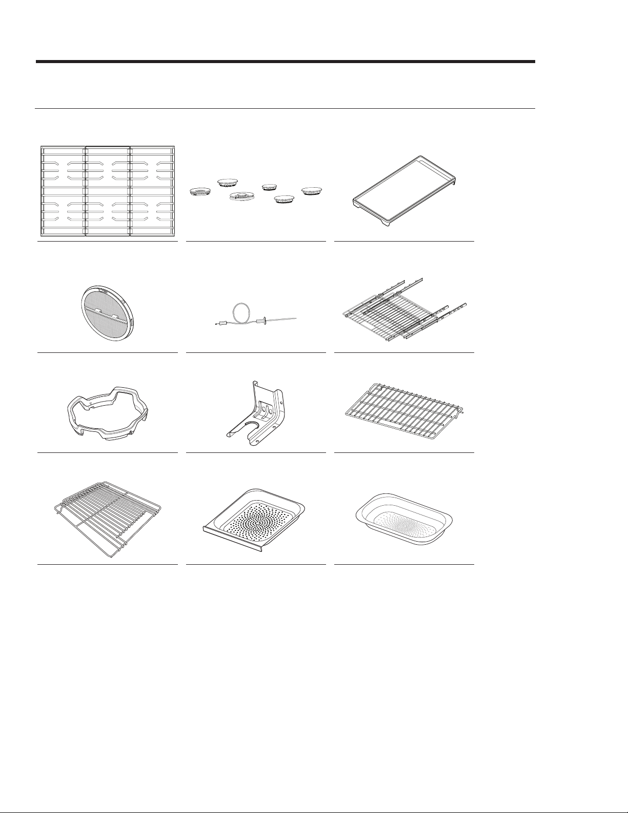
Product Specifications
What Is Included (DOP48M96D)
The range comes with brass and porcelain burner caps to suit customer preference.
Grates (3) Burner heads (6) and Burner
caps (7)
Griddle (1)
Convection filter (3) Temp. Probe (2) Glide racks (2)
WOK ring (1) Anti-tip bracket (1) Wire rack (1)
Steam tray (2)* Half steam tray (2)*Small rack (1)*
*Steam ovens only
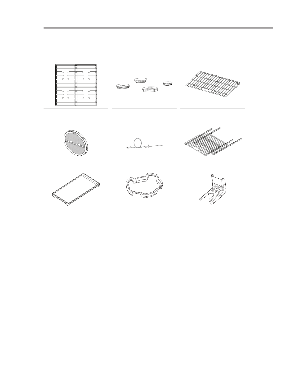
Product Specifications
What Is Included (DOP36M94D)
English 11
The range comes with brass and porcelain burner caps to suit customer preference.
Grates (2) Burner heads (4) and Burner
caps (5)
Wire rack (1)
Convection filter (2) Temp. Probe (1) Glide racks (2)
Griddle (1) WOK ring (1) Anti-tip bracket (1)
12 English
Product Specifications
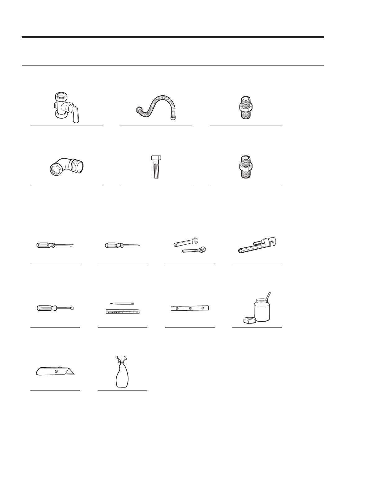
Needed Tools and Parts
Gas line shut-off valve Flexible metal appliance
connector ½ in (ID) x 5 ft
Flare union adapter ¾ in
(NPT) x ½ in (ID)
135-degree elbow
(optional)
Lag bolt or ½-in (OD)
sleeve anchor
Flare union adapter ½ in
(NPT) x ½ in (ID)
Tools Needed
Flat-blade
screwdriver
Phillips
screwdriver
Open-end or
adjustable wrench
Pipe wrench (2)
Nut driver Pencil and ruler Level Pipe joint
compound
Utility knife Soapy water
solution
Parts Needed
Installation Requirements
Pre-Installation Checklist
English 13
1. Before installing the range, read this manual thoroughly.
2. Plan for a location where the range will not be subject to strong drafts.
3. Remove packaging, grate boxes, regulator with literature, and literature package
from the range, verify that all items are present before beginning the installation.
General Requirements
Clearances and Dimensions
• For OTR over gas stove, follow the local gas code.
• For safe operation, provide adequate space between the range and combustible surfaces.
Location of the electrical outlet and gas piping may be adjusted to meet the dimensions and
clearances in this manual.
• The range may be installed flush to the rear wall. A non-combustible material must be
installed on the rear wall between the range and hood. It is not necessary to install non-
combustible material directly behind the range. Openings in the wall behind the range or in
the floor below must be sealed.
• Canada only: A free-standing range shall be installed at least 4.7 in. (12 cm) from all adjacent
surfaces.
CAUTION
The range complies with the maximum allowable wood-cabinet temperature of 194 °F (90 °C).
Ensure the adjacent wall covering, countertops, and cabinets can withstand such heat to avoid
discoloration, delamination, or melting.
Minimum Dimensions
WARNING
Regarding overhead cabinets, a hood should be installed that projects at least 5" (12.7 cm) beyond
the cabinetry face to dissipate heat in those cabinets. The hood must consist of sheet metal at
least .0122" thick. Install the hood with at least 1/4" clearance between it and the bottom of the
combustible material or metal cabinet. The hood must be at least as wide as the range and
centered over it. Clearance between the cook surface and hood bottom must be at least 24". (For
above-range cooking appliances, follow that appliance's installation criteria.)
•
30" (76.2 cm) minimum clearance between the cook surface and bottom of an unprotected wood/
metal cabinet; or if no 30" (76.2 cm) min. clearance, 24" (61 cm) min. when the bottom of the
wood/metal cabinet is protected by at least .25" (.64 cm) flame-retardant millboard covered with
at least No. 28 MSG sheet steel, .015" (.038 cm) stainless steel, .024" (.061 cm) aluminum,
or .02" (.051 cm) copper.
• 18 in. (45.7 cm) minimum between the countertop and adjacent cabinet bottom.
14 English
Front of open door
Front of handle
Front of bull nose
Front panel
Rear of oven door
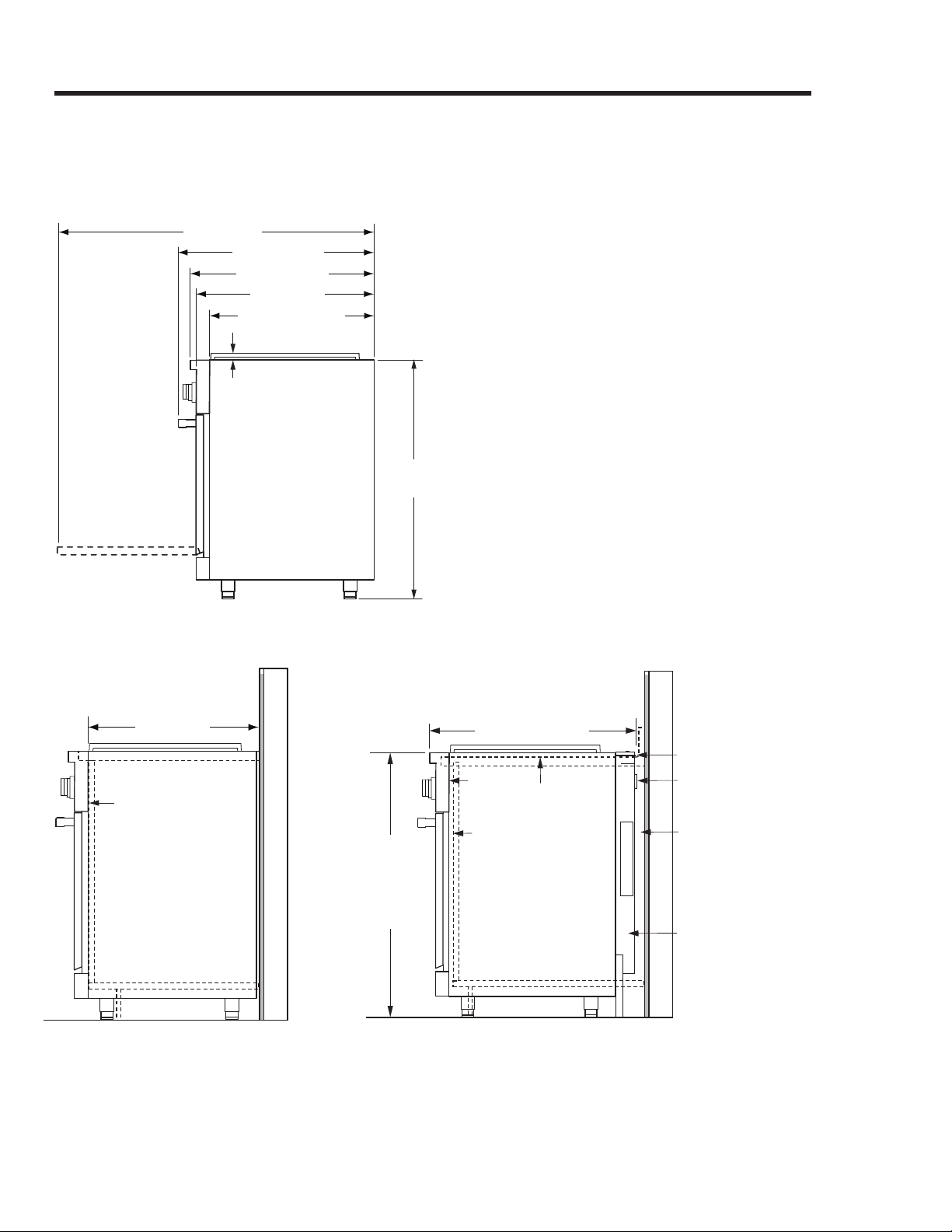
48” (121.9 cm)
28 1/8” (71.4 cm)
27 1/2” (69.9 cm)
26” (66.0 cm)
15/16” (2.4 cm) top of
trim to top of grates
(cooking surface)
36 1/8"
(91.8 cm)
Installation Requirements
Product Dimensions—
Product tolerances: ±1/16” (±1.6 mm)
DOP36M94D: 35 7/8” (91.1 cm) wide ; DOP48M96D: 47 7/8” (121.6 cm)
24” (61.0 cm)
Cabinet
face
29 7/8” (75.9 cm)***
Countertop
height:
36 3/16"
(91.9 cm) min.
37 1/2 "
(95.3 cm) max.
3/8” min. (1.0 cm)
flat countertop
overhang needed
behind cutout
Stiffener
3/8” min. (1.0 cm)
space behind
downdraft vent
chassis to clear
stiffener
Countertop*
Back of
control
panel
Range Installed
Range Installed with Downdraft Vent
MRV36-ER or
MRV48-ER
downdraft vent
23 15/16” (60.8 cm)
Cabinet
face

English 15
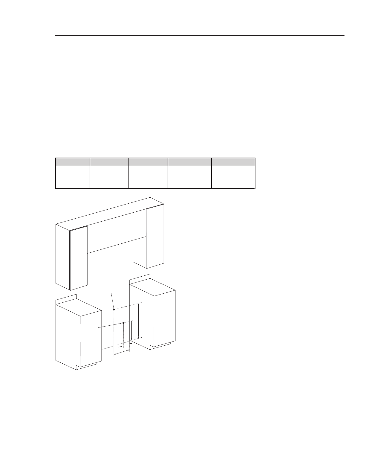
Installation Requirements
Cabinet Dimensions
Maintain all max/min dimensions and clearances in the diagrams below for safe use.
CUTOUT DIMENSIONS
Range Model A B C
DOP36M94D
42” (106.7 cm)*; 36” (91.4 cm)**
36” (91.4 cm)**; 36 1/8” (91.7 cm)***
33 1/2” (84.8 cm)
DOP48M96D
54” (137.2 cm)*; 48” (121.9 cm)**
48” (121.9 cm)**; 48 1/8” (122.2 cm)***
43 1/2” (110.5 cm)
A
B
C
13” (33.0 cm)
max.
5
Non-combustible
surface along back wall
recommended
10” (25.4 cm)
min. to
combustible
side walls
above range
(both sides)
Note 2
Note 2
B
acksplash
3” (7.6 cm)
3/8" (1.0 cm) min.
flat countertop
overhang
Non-combustible rear
wall (recommended)
10" (25.4 cm) min.
to combustible side
walls above range
(both sides)
Cutout with Optional Downdraft Vent
(Top View)
Standard Cutout
with Range Hood
1. Vertical f
rom range
grate
le
vel
to
combustible overh
ead surface; if in
stalling an ove
rhe
ad hood, se
e
hood specifications for minimum re
quire
d clearances.
2.
Cabinet/countertop depth is at the customer's discretion, but cabinet face must not protrude beyond the
rear of the front panel. (See Product Dimensions, Pg. 14.)
3. Consult local codes for exact location requirements.
4. Vertical from grate level to combustible surface.
5. Does not apply to cabinets more than a horizontal distance of 10" (25.4 cm) from the range edge.
*Recommended, **Minimum, ***Maximum
Top of
finished
counter
30” (76.2 cm)
max.
1
Suggested
location of
utilities
3
18" (45.7 cm)
4, 5
37 1/2"
(95.3 cm)
max.
Grate
level
B
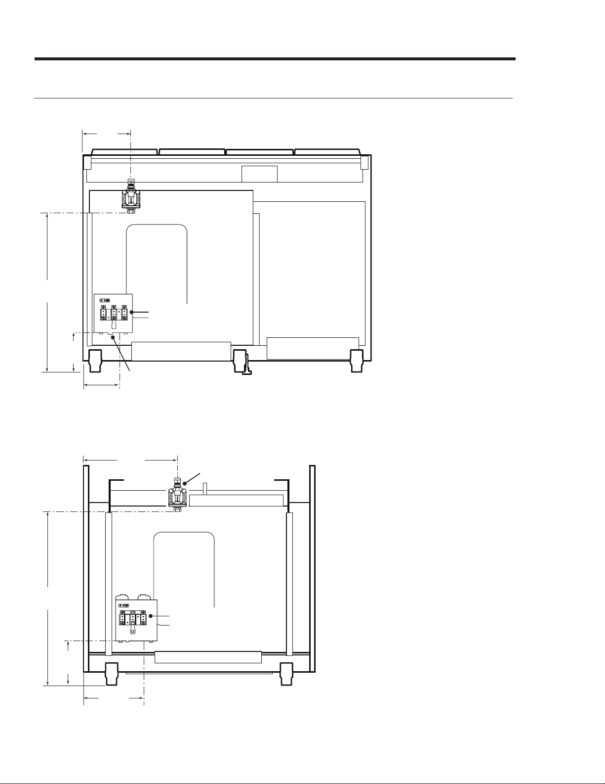
16 English
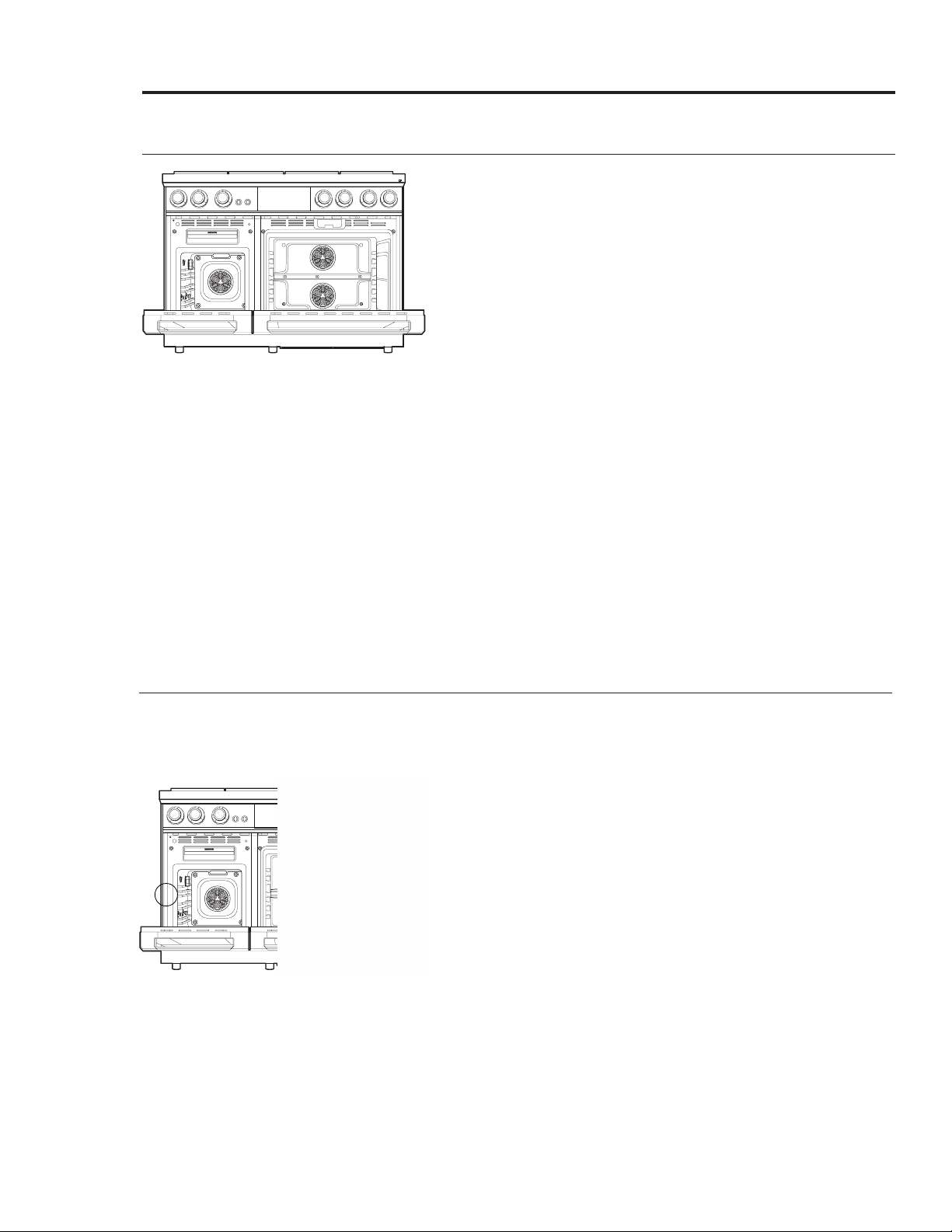
DOP48M96D (rear)
Gas Inlet
Shown with
electrical access
cover removed
E - Electrical wiring
access hole in bottom
Installation Requirements
Location Requirements
8 1/8"
(20.6 cm)
26 5/8"
(67.6 cm)
5 1/2"
(13.9 cm)
6 5/8"
(16.8 cm)
DOP36M94D (rear)
Gas Inlet
Shown with electrical
access cover removed
1. Measurement with
appliance
legs adjusted to lowest height.
2.
Th
e h
ole s
ize f
or t
he e
lectrical
wiring m
ay b
e i
ncreased t
o 1
1/8” (
2.
9 cm) by removing the
conduit bracket in the bottom
of the range electrical box.
24 1/4"
(61.6 cm)
6 5/8"
(16.8 cm)
8 7/8"
(22.5 cm)
11 3/16"
(28.4 cm)
English 17
Installation Requirements
Gas and Electrical Service
• See below for the recommended location of the gas inlet and electrical junction box/receptacle.
Existing utilities may be used if they are compatible with this range. Check local building codes
for allowed gas-valve locations.
• An external manual shut-off valve must be installed between the gas inlet and range so the
range's gas supply can be turned on/off. Installation must allow access to the gas shut-off valve
when the unit is installed and access to the remote circuit-breaker panel/fuse box without
moving the range.
• The gas-supply piping and shut-off valve, and the electrical junction box/receptacle must be
located so as not to interfere with the range when it is installed.
• The junction box and gas-shut off valve must be located so the range can be pulled out for
service without being disconnected.
G
E
D
F
Recommended
position for
Gas stub
Recommended
position for
electrical outlet
Model D E F G
DOP36M94D
8 7/8"
(22.5 cm)
6 5/8"
(16.8 cm)
11 3/16"
(28.4 cm)
24 1/4"
(61.6 cm)
DOP48M96D
5 1/2"
(13.9 cm)
6 5/8"
(16.8 cm)
8 1/8"
(20.6 cm)
26 5/8"
(67.6 cm)
18 English
Installation Requirements
Gas Requirements
Provide Adequate Gas Supply
This oven's installation must conform to local codes or, in their absence, with the National Fuel Gas
Code, ANSI Z223.1/NFPA 54.
This range's cooktop is designed to operate at a manifold pressure of 5 in. (13 cm) of water column
for natural gas/natural gas at high altitude (NG-H) or 10 in. (25.4 cm) of water column for LP
(propane)/LP at high altitude (LP-H).
Verify that the oven is right for the provided gas service.
When verifying regulator function, inlet pressure must be at least 1 in. (2.5 cm) greater than the
operating (manifold) pressure as given.
GAS SUPPLY PRESSURE REQUIREMENTS*
Gas Type Minimum Manifold Pressure Minimum Gas Supply Pressure**
Natural Gas
5” Water Column
6” Water Column
*The gas supply pressure for testing the regulator setting shall be at least 1" water column (249 Pa) above the
specified manifold pressure; **Maximum gas supply pressure for all models: 1/2 psi.
LP (propane) Gas
10” Water Column
11” Water Column
NOTE
• The pressure regulator at the inlet of the cooktop manifold must stay in the supply line whether
or not natural or LP gas is used.
• Use only the range's regulator, which must be installed in the gas line that runs from the
cooktop gas inlet to the gas shut-off valve.
• An external manual shut-off valve must be installed between the gas inlet and range for turning
on/off gas to the appliance.
• Ensure the connectors are installed by a qualified installer.
• To avoid leaks and personal injury, never install used connectors on a new product. Use only
new, flexible connectors.
Special Gas Requirements (gas models sold in Massachusetts)
WARNING
• Gas leaks may occur in your system, creating a hazardous condition. Such leaks may not be
detected by smell alone; thus, gas suppliers recommend installing a UL-approved gas detector
per manufacturer specifications.
• The range must be installed by a plumber or gas fitter certified by the State of Massachusetts.
• A T-handle manual gas valve MUST be installed in the gas-supply line to your range.
• If using a flexible gas connector, multiple lines must not be connected in series.
Installation Requirements
Electrical Requirements
English 19
Follow these directions to reduce risk of property damage, personal inju
ry, or death.
WARNING
The owner shall ensure that the electrical service meets requirements and that the electrical outlet
is installed by a licensed electrician.
All Ranges
• Do not use an extension cord or adapter plug with this range.
• This range must be plugged in to a properly grounded outlet. (Check with a qualified electrician
if you doubt that the outlet is properly grounded.)
• Do not alter the power plug. Have a proper outlet installed by a qualified electrician.
• All wiring/grounding must comply with local codes or, in their absence, with the National
Electrical Code, ANSI/NFPA No. 70 – Latest Revision (US), or the Canadian Electrical Code CSA
C22.1 – Latest Revisions and local codes.
• The wiring diagram is on the back of the range.
• A dedicated circuit breaker is recommended.
• Use this chart to identify the minimum recommended dedicated circuit protection.
KW Rating (240 V) Recommended Circuit Size (Dedicated)
7.3 KW - 9.6 KW 40 Amp
9.7 KW - 12.0 KW 50 Amp
20 English
Installation Instructions
Preparing for Installation
WARNING
• If the gas or electric service provided does not meet the product specifications, do not proceed
with the installation. Call the dealer, the gas supplier or a licensed electrician.
• Before installing the range, you must locate and secure the anti-tip bracket to the floor.
Unpacking the Range
Unpack the parts box and verify that all required components have been provided. If any item is
missing or damaged, please contact your dealer immediately. Do not install a damaged or
incomplete appliance.
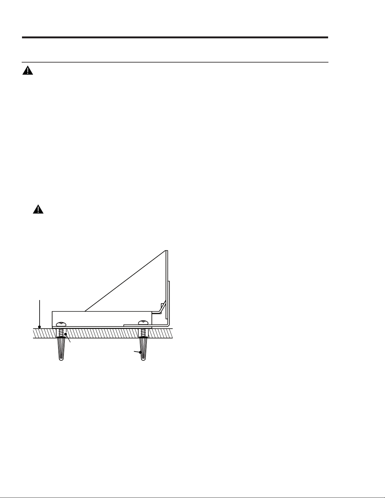
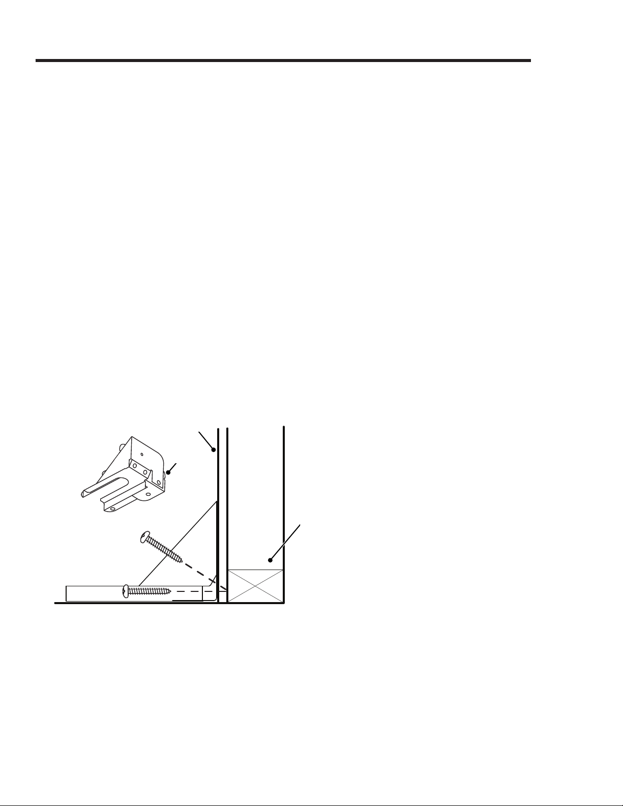
Floor-Mounting the Anti-Tip Bracket
WARNING
To perform as designed, the anti-tip bracket must attach to the concrete slab or wood sub-floor
below any upper flooring (including cement board). Do not attach the anti-tip bracket directly to
floor coverings such as ceramic/asphalt tile or linoleum.
Floor covering
Sub-floor
Screws attached
through flooring
into sub-floor
Installing the Anti-tip Bracket and Foot
There are two ways to mount the anti-tip bracket: Floor mounting (preferred), and wall mounting
(Pg. 22). Use this method if floor mounting is unsuitable; however, if the range's front panel is over
26 1/2” (67.3 cm) from the back wall or if the floor is too thick, floor mounting must be used.
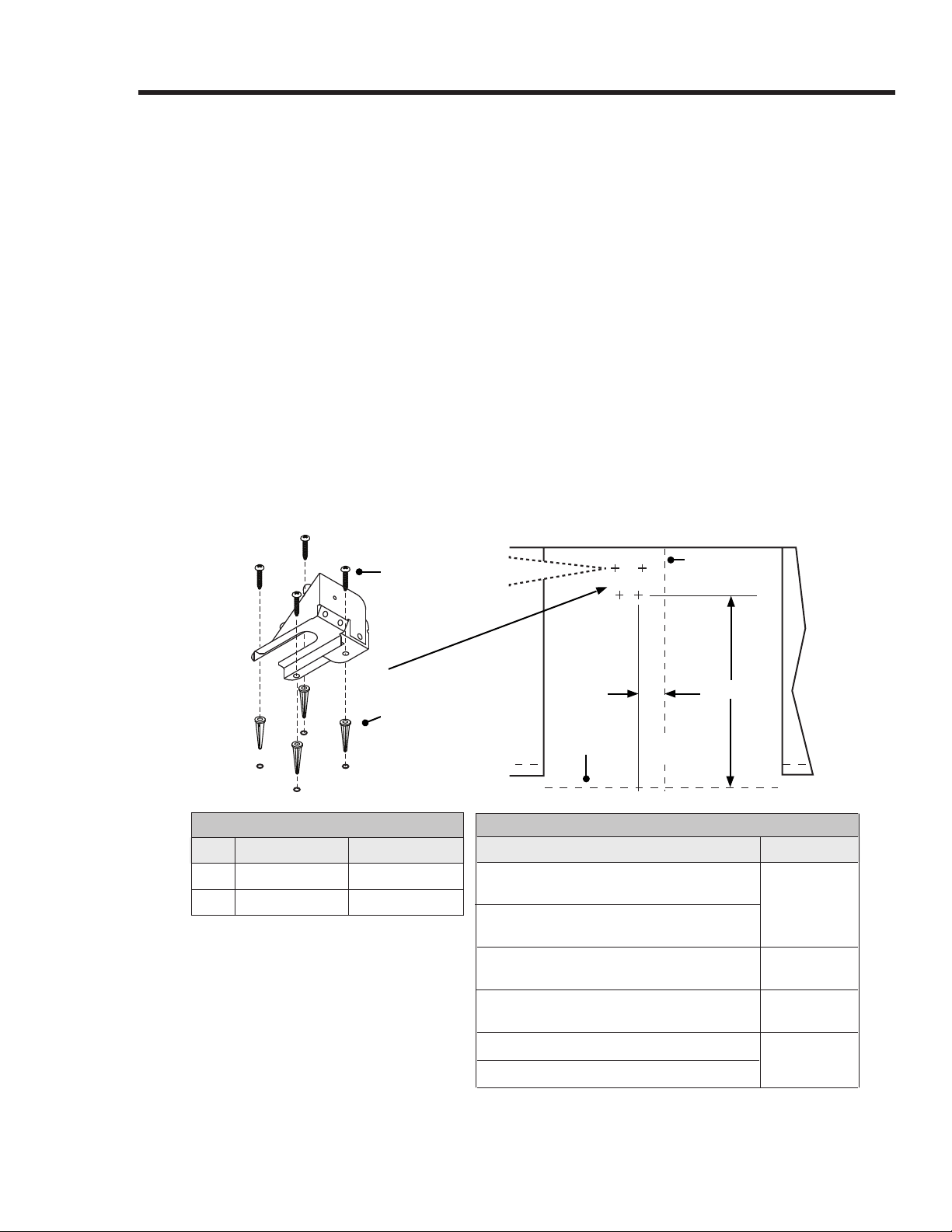
Anchors shown
(concrete
sub-floor only)
•Four plastic anchors are provided with
three sizes (4 each) of #8 or #12 Phillips
head screws for attaching the anti-tip
bracket to the floor. Use both anchors
and four of the screws to attach the
bracket to a concrete sub-floor. Do not
use anchors on a wood sub-floor.
•Determine the location of the range
center line and front panel for the
range’s final position based on the
Product Dimensions (Pg. 14) and the
actual cabinet/cutout dimensions used
for the installation.
Installation Instructions
Floor-Mounting the Anti-Tip Bracket, cont.
English 21
•Determine the required position of the anti-tip bracket, based on the diagram below. Mark the
4 mounting-hole locations on the floor with a pencil.
•Determine the screw size. The minimum full thread depth (portion of screw threaded into
wood/slab) is 3/8” (1 cm) for wood and 5/8” (1.6 cm) for concrete. (See SCREW SIZE table,
below, for correct screw sizes.)
Attaching the Bracket to a Concrete Floor
1. Drill four 3/8” dia. countersink holes through flooring to but not into the concrete.
2. Through these holes, drill 4 anchor holes 1-1/4” (3.2 cm) into the concrete with a 3/16”
masonry bit. This hole length is longer than the anchor. Clean out the holes, and tap in each
anchor so its top is flush with the concrete surface.
3. Align the bracket and anchor holes, then insert and tighten the screws.
Attaching the Bracket to a Wood Floor
1. Ceramic, stone, other hard flooring over wood: Drill 4 countersink holes to access the
wood for drilling pilot holes.
2. Drill 4 pilot holes in the wood with a drill bit (1/16” dia. for #8 screws, 1/8” dia. for #12
screws). Align the bracket and pilot holes, then insert and tighten the screws.
C
B
A
TOP
VIEW
Range center line
#8 x 1” #8 x 1 1/4”
or #12 x 1 3/4 screw,
4 places (see text)
Anchor, 4 places:
use for concrete
floor only
Range
front panel
SCREW SIZE
Sub-Floor Type/Floor Covering Thickness Screw Size
Concrete/wood subfloor, no floor covering
over top
#8 x 1*
Concrete/wood subfloor, floor covering up to
1/4” thick
Concrete/wood subfloor, floor covering over
1/4” up to 1/2” thick
#8 x 1 1/4*
Wood sub-floor, floor covering over 1/2” and
up to 1 3/16” thick
#12 x 1 3/4*
Concrete under floor covering over 1/2” thick
Purchase
separately**
Wood under floor covering over 1 3/16” thick
*Included with range
;
**determine required depth
based on info in Step 3, and
purchase from hardware store.
ANTI-TIP BRACKET PLACEMENT
Dim
.
DOP36M94D DOP48M96D
A
13” (33.0 cm) 3 1/2” (8.9 cm)
B
22 1/2” (57.2 cm) 22 1/2” (57.2 cm)
22 English
Installation Instructions
Installing the Anti-Tip Bracket and Foot, cont.
Wall-Mounting the Anti-Tip Bracket
For this option to be suitable, the range front panel must be 26 1/2" (67.3 cm) or less from the
wall, and the bracket screws must be able to engage the base plate inside the wall. Notches on
the sides of the bracket indicate the minimum height of the base plate and that any floor
covering thickness will not impede secure threading.
To determine if the base height is suitable:
• Determine the location of the range centerline and front panel when the range is in its final
position based on the product dimensions on Pg. 14 and the actual cabinet/cutout
dimensions used for the installation.
• Determine and mark the required position of the anti-tip bracket, based on the diagram on
Pg. 21. Push the bracket up against the wall in the mounting location.
• With a pencil, make a dot next to the notches on both sides of the bracket. Determine if the
base plate is as high as the notches by drilling test holes into the wall at both dots with a
1/16” drill bit. Drill just deep enough to see if the bit contacts the base plate. If there is
contact, the location will support wall installation of the bracket. If there is no contact, wall
mounting is unsuitable, and either floor mounting must be used, or the wall must be altered
so there is base material above the notches.
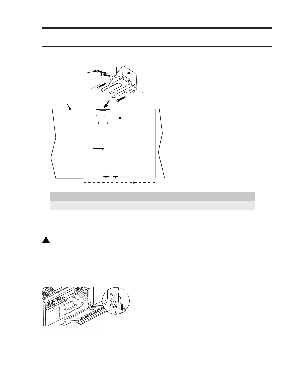
To install the bracket, place it against the wall in the mounting location. Using a drill with 1/8"
diameter drill bi
t, drill four (4) 1 5/8” deep pilot holes perpendicular to the screw seating
surfaces shown below. A
ttach th
e bracket to th
e wall as sh
own with the four (4) included #12 x 1
¾ screws.
Drywall
Notch
Wall
Base plate
Anti-tip
bracket
Installation Instructions
Wall-Mounting the Anti-Tip Bracket, cont.
English 23
C C
C
Back wall
#12 x 1 3/4” screw,
4 places
This hole lines up with
bracket center line
Range center line
Range front
p
anel
Bracket
center
line
ANTI-TIP BRACKET PLACEMENT
Dimension DOP36M94D DOP48M96D
C 14 1/8” (35.9 cm) 3 1/2” (8.9 cm)
Installation Instructions
Preparing for Installation, cont.
Removing the Oven Door
WARNING
• Do not try to disengage the hinge catches with the door(s) removed. The hinge springs could
release causing personal injury.
• Do not lift or carry the oven door(s) by the handle.
Catch
Retaining arm
1. Open the door fully.
2. With needle-nose pliers or a slotted
screwdriver, rotate the catch over the
retaining arm on each hinge.
24 English
Installation Instructions
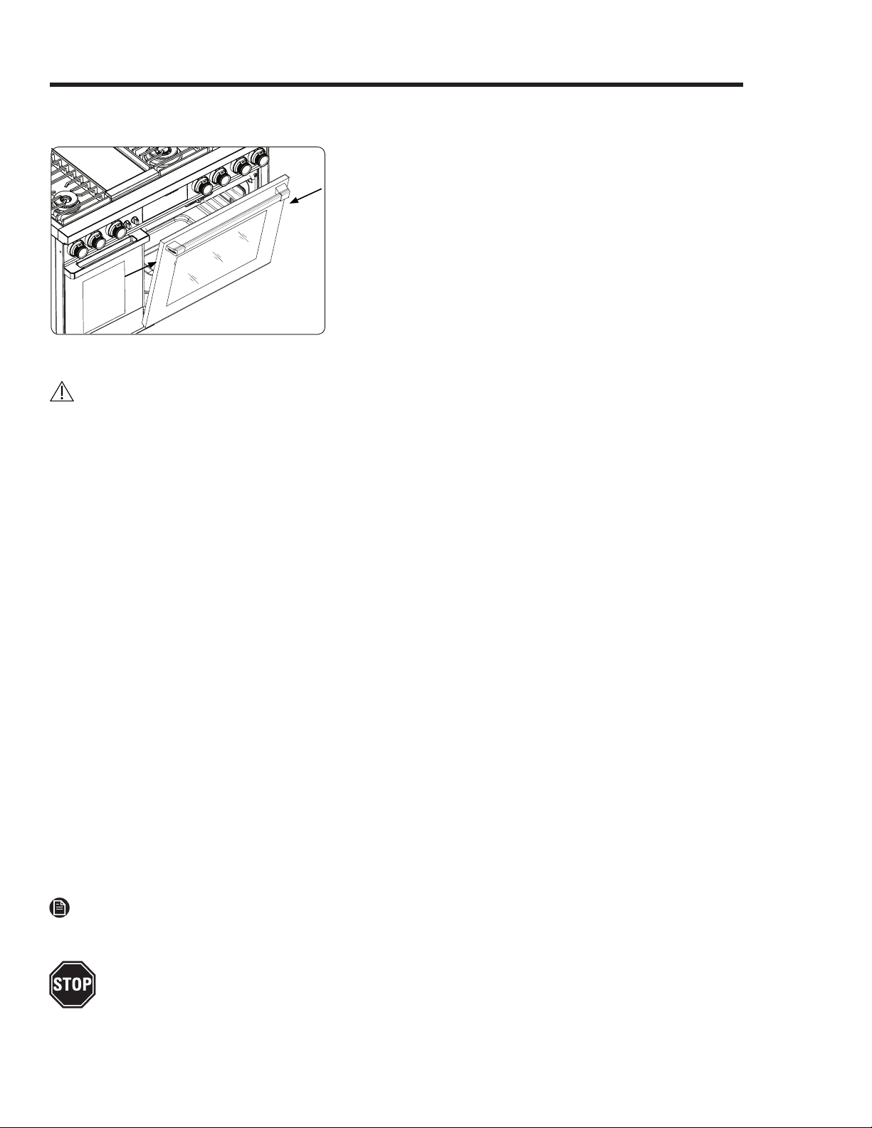
Removing the Oven Door, cont.
Door
Gripping
Points
3.
4.
Lift the oven door to about a 15° angle from
vertical.
With both hands, grasp the door just below the
handle, and pull up slightly.
5. On the bottom-right edge of the door, pull out
the wire connector, and disconnect the wires.
6. Lift the door away from the oven.
Electrical Connection
C
AUTION
For personal safety, do not use an extension cord with the range. Remove the house fuse or open
the circuit breaker before starting the installation.
The range must receive the proper voltage and frequency and connect to an individual, properly
grounded branch circuit protected by a circuit breaker or fuse having amperage as specified on the
rating plate (left-side door trim). The range's power hookup should be done by a qualified
electrician. After installation, have the electrician show you where to turn off power to the range.
Consult local utilities for applicable codes. Failure to wire your oven per these codes could create a
safety hazard. If there are no such codes, your range must be wired and fused per the National
Electrical Code, ANSI/NFPA No. 70–Latest Edition. For a copy, write: National Fire Protection
Association, Batterymarch Park, Quincy, MA 02269
Effective Jan. 1, 1996, the National Electrical Code requires that new construction use a 4-
conductor connection to an electric range. When installing an electric range in new construction,
follow Steps 2 and 3 for 4-wire connection.
• A 3-wire or 4-wire, single-phase A.C. 240 Volt, 60 hertz electrical system is required. If the home
electrical service does not meet the above specifications, have a licensed electrician install an
approved outlet.
• Use only a 3-conductor or a 4-conductor UL-listed range cord. These cords may be provided
with ring terminals on wire and a strain relief device.
• A range cord rated at 40 amps with 125/250 minimum volt range is required. (A 50 amp range
cord is not recommended but if used, it should be marked for use with nominal 1⅜" diameter
connection openings. Center the cable and strain relief within the knockout hole to keep the
edge from damaging the cable.)
• Because range terminals are inaccessible when the range is in position, flexible conduit/cord
must be used.
NOTE
If conduit is being used, see Pg. 25.
ALL NEW BRANCH-CIRCUIT CONSTRUCTION, MOBILE HOMES, RECREATIONAL VEHICLES, AND
INSTALLATIONS WHERE LOCAL CODES PROHIBIT GROUNDING THROUGH NEUTRAL, REQUIRE A
4-CONDUCTOR UL-LISTED RANGE CORD.
English 25
InstalInstallation lation InstructionInstructionss
Installing the Flexible Conduit
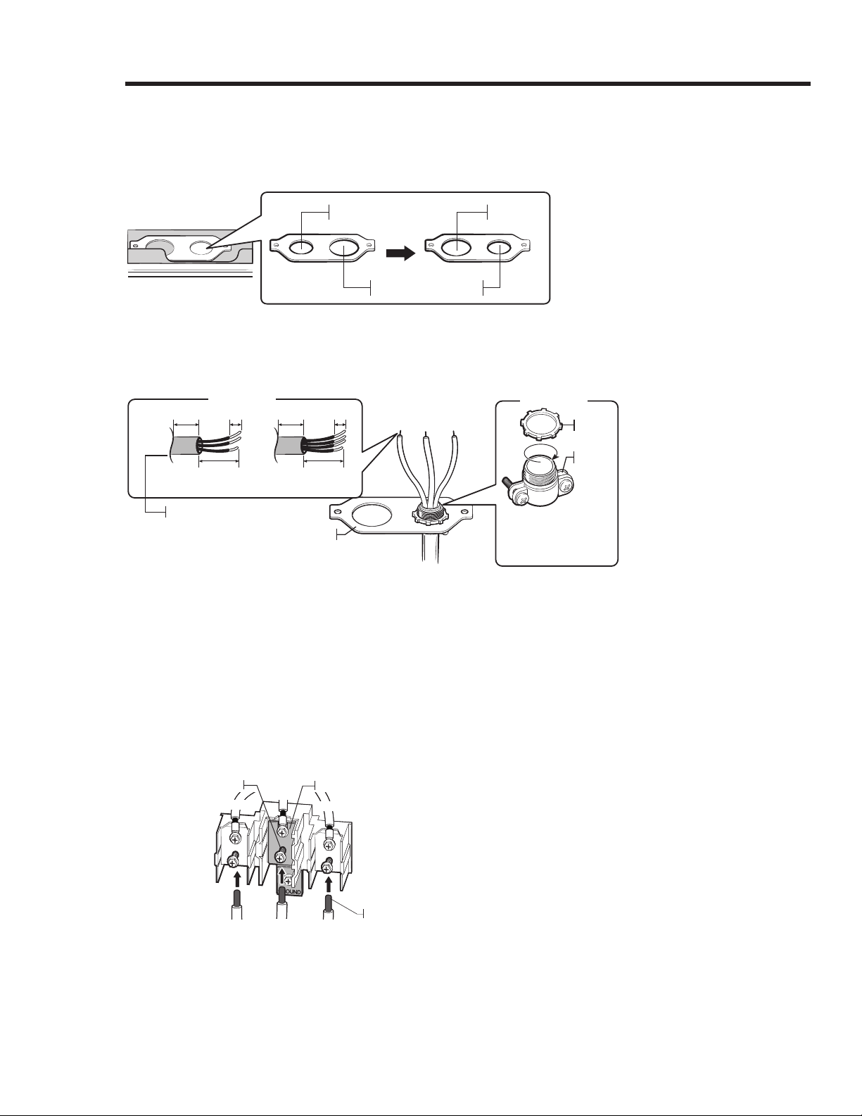
Remove the conduit connection plate from the rear of the drawer body, and flip it as shown.
(Use the 1⅛" hole.)
1⅛" 1⅜"
1⅛"
1⅜"
1. Prepare the conduit cord (Figure 1).
2. Install the conduit cord (Figure 2).
Conduit connection plate
Strain relief
Ring
Body
Figure 2
1"
3½"
⅜" 1"
3½"
3 wire 4 wire
Knockout surface
Figure 1
⅜"
Conduit installations: Insert the strain relief (not included) i
n the 1⅛"conduit hole, thread the
conduit cord through
th
e body of the strain relief, and fasten th
e ring, th
en reinstall th
e bracket.
Installing a 3-wire Conduit
• Aluminum building wire may be used but must be rated for the correct amperage and
voltage. Connect wires according to Step 4 depending on the number of wires.
• Wire used, location/enclosure of splices, etc., must follow good wiring practices and local
codes.
White
Black
Red
Ground strap
Neutral terminal
Wire tips
Red
White
Black
1.
2.
3.
Loosen the three lower screws on the terminal
block.
Insert the white/neutral bare wire tip through the
bottom-center block opening. (Some models: the
wire inserted through the ground-strap opening
into the bottom-center block opening.)
Insert the left and right wire tips into their
respective block openings.
4. Tighten the screws to 35 – 50 in.-lbs.(Any tighter
may damage the wires.)
26 English
Installation Instructions
Installing the Flexible Conduit, cont.
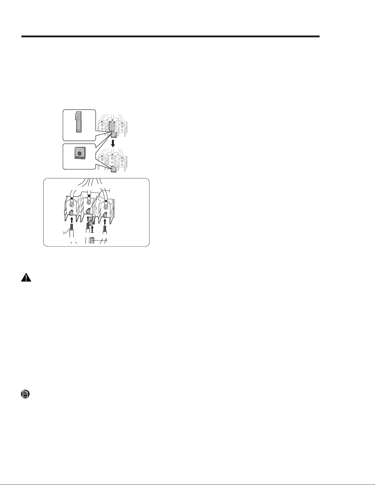
Installing a 4-wire conduit
• Aluminum building wire may be used but it must be rated for the correct amperage and
voltage. Connect wires according to this Step 4 depending on the number of wires.
• Wire used, location and enclosure of splices, etc., must conform to good wiring practices and
local codes.
Ground strap
Ground plate
Red
Neutral
terminal
Ground wire (Green)
Wire
tips
White
Black
Red
1. Loosen the 3 lower screws on the terminal
block. Remove and retain the ground screw
and ground plate.
2. Cut and discard the ground strap. Do not
3.
4.
5.
6.
discard any screws.
Insert the ground bare wire tip between the
range frame and ground plate (removed
earlier), and secure it with the ground screw
(removed earlier).
Insert the wire (white/neutral) tip through
the bottom center of the block opening.
Insert the left and right wire tips into their
respective block openings.
Tighten the screws to 35 – 50 in.-lbs.(Any
tighter may damage the wires.)
Black
White
Gas Connection
WARNING
• Turn off the gas-supply valve, and turn off power to the range at the circuit breaker or fuse box
before connecting the gas line.
• Do not apply excessive pressure when tightening gas connections and fittings.
• Do not use Teflon tape or plumber’s putty on gas flex-line connections.
• Maximum gas-supply pressure to the regulator must not exceed ½ psi (pounds per square inch)
or 3.5 kPa.
• The range and shut-off valve must be disconnected from the gas-supply piping for pressure
testing that exceeds ½ psi (3.5 kPa).
• The range must be isolated from the gas-supply piping by closing the shut-off valve for pressure
testing at or below ½ psi (3.5 kPa).
•
Check all gas lines for leaks as instructed to avoid fire/explosions hazard. Do not check for leaks
with a flame.
NOTE
The gas-pressure regulator is factory set for the type of gas used with the range. To verify that the
range is compatible with the available gas, see the rating label (oven left door trim). Consult your
dealer if the range is incompatible with the supplied gas.
Anti-tip
bracket
Anti-tip foot
English 27
Installation Instructions
Gas Connection, cont.
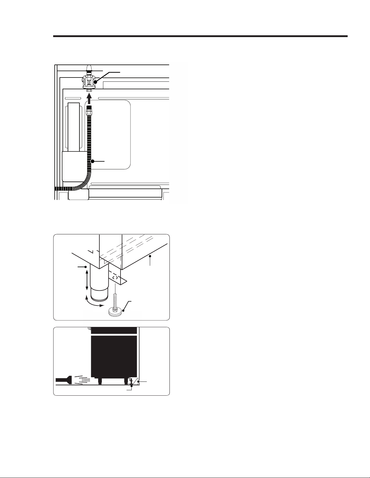
Before sliding the range into the cabinet
1. Turn off the gas-supply valve, and turn off
power to the range.
2. Connect a flexible gas line to the shut-off valve
installed on the stub out. The line must be long
enough that the range can be pulled out for
service without disconnecting the line.
3. Slide the gas line up through the chassis' access
holes to the regulator. (Move the wires inside
the access holes to keep them from catching on
the gas line.)
4. Connect the gas line to the regulator.
5. Turn off all cooktop controls, then turn on the
gas supply.
6. With a soap-and-water solution, check all lines
and connections for leaks.
7. Turn off the gas-supply valve.
Regulator connection
Gas line
Final Installation
Back of range
Rear leg
1 1/4” *
* Distance to floor:
4 1/16” to 5 5/16”
Anti-Tip Foot
(location varies)
up
down
1.
2.
3.
Peel the protective sheeting from the range.
Measure from floor to countertop. Adjust the
leveling legs as needed to position the trim
around the cooktop even with or above the
countertop.
Turn to lower the anti-tip foot at the back of
the range until it is 1/16” (2 mm) off the floor.
4. Slide the range into the cutout so the anti-tip
foot engages the anti-tip bracket. (Use a
flashlight to verify.)
5. With a level, check that the range does not tilt
in any direction. (Adjust the legs to level the
range as needed.)
28 English
Installation Instructions
Reinstalling the Oven Door(s)
WARNING
To avoid personal injury or damage to the door from it falling off its hinges:
• Make sure that the notch on the bottom of each hinge rests on the lower lip of each hinge
receptacle before trying to open the oven door.
• Flip the hinge locks toward the front of the range immediately after installation of the door.
1. Grasp the oven door on both sides, and hold it at a 15° angle from the front of the oven. Slide the
hinges into their slots, resting the bottom of the hinge arms on the hinge receptacles. Maintain
the 15° angle with one hand while pushing in on each bottom corner of the door, until the notch
on the bottom of each hinge slips over the lower lip of each hinge receptacle.
NOTE
Wire connector under the right side of the door
should be connected.
2. Lower the door to the fully opened position.
3. Rotate the two hinge locks toward the oven.
4. Slowly and carefully open and close the
door completely to ensure that it is properly
installed.
5. Remove any packaging from inside the
oven(s).
H
inge
slot
Notch
(h
in
ge
bottom)
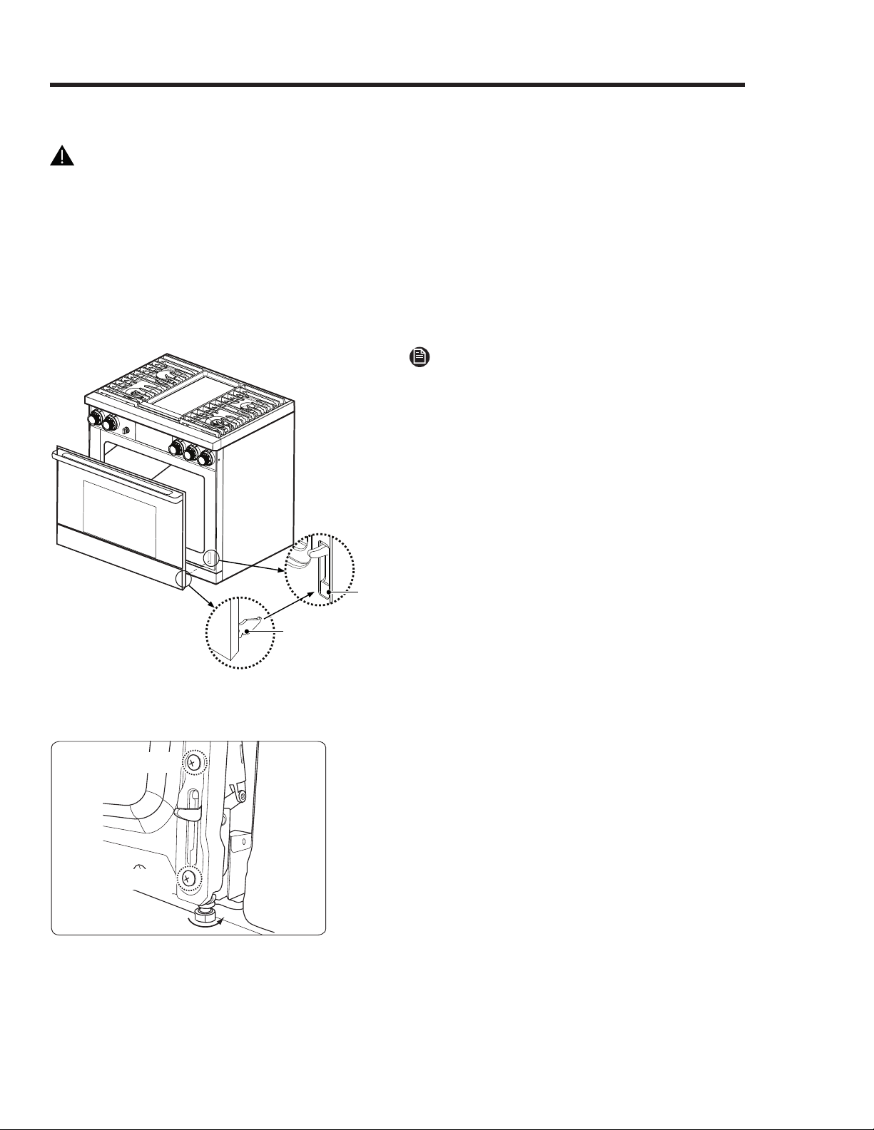
Adjusting the Do
or (DOP48M96D only)
Steps 1 and 3
Steps 1 and 3
Ensure the oven doors are parallel and flush. To
do this, use the three bolts (one on the right-
upper side, and one under the each hinge) .The
upper bolt adjusts the door hori
zontally. The
lower two bolts adjust th
e door vertically.
To adjust door vertically:
1. Remove the
door, then remove 2 screws on
each door-hinge latch.
2. Adjust the bolt under each latch.
3. Re-attach and tighten the 2 screws.
4. Re-install the door.
English 29
Installation Instructions
Adjusting the Door (DOP48M96D only), cont.
Lifting the door-hinge latches too much makes
fastening the two screws difficult.
To adjust door side to side, turn the upper bolt (see
left).
NOTE
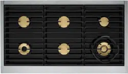
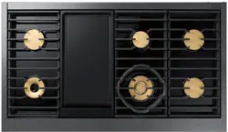
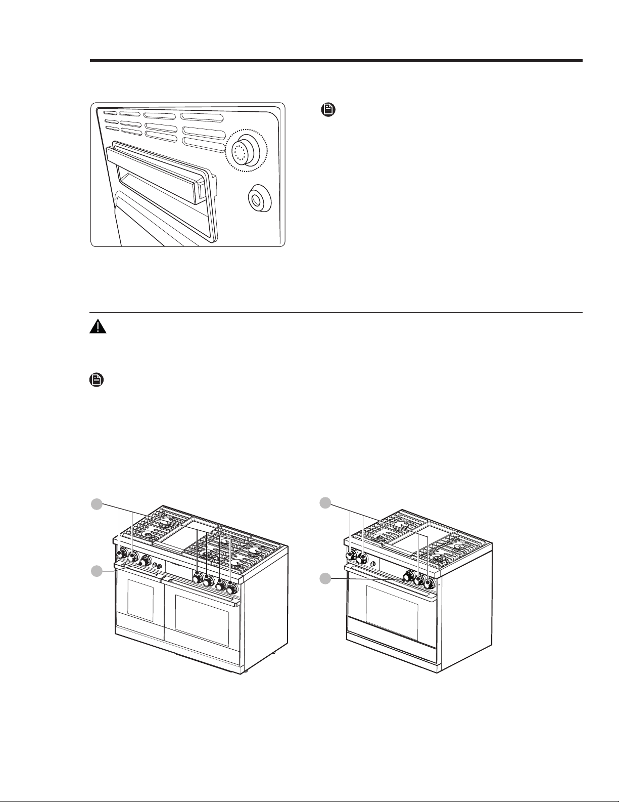
Installing the Burner-Control Knobs
WARNING
Installing the range knobs in the wrong position may result in damage to the griddle included with
the range. The knobs for the center burners are marked with the maximum griddle settings.
NOTE
When installing the knobs, align the “D” shaped opening on the back of the knob with the end of the
valve shaft. Gently push the knob on until it stops.
Two types of knobs come with the range: Griddle (no flame icon) and burner.
1. Put the griddle knob on Position A.
2. Put the remaining knobs on Position B.
A
B
A
B
48" Model: DOP48M96D 36" Model: DOP36M94D
30 English
Installation Instructions
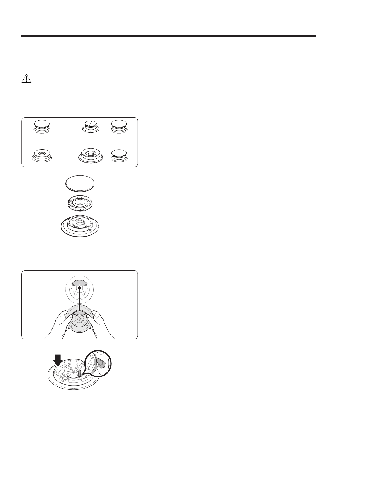
Rangetop Assembly
Assembling the Burners
CAUTION
• Do not operate the rangetop burners unless properly assembled.
•
Do not push in a rangetop knob while removing the burner; a slight electrical shock might result.
• Do not remove the top or touch a burner electrode while another burner is on.
1. Place the burner heads on the burner bases as
shown at left. (The electrodes fit in the slot in the
bottom of the heads.) The heads should be flat
and parallel to the rangetop.
2. Place the matching size caps on top of each
rangetop burner head.
Dual Burner Head/Cap
1. Orient the burner head so the electrode opening
aligns with the electrode.
2. Install the burner head so the electrode passes
through its opening in the head. Ensure the
burner head lies flat atop the base.
English 31
Installation Instructions
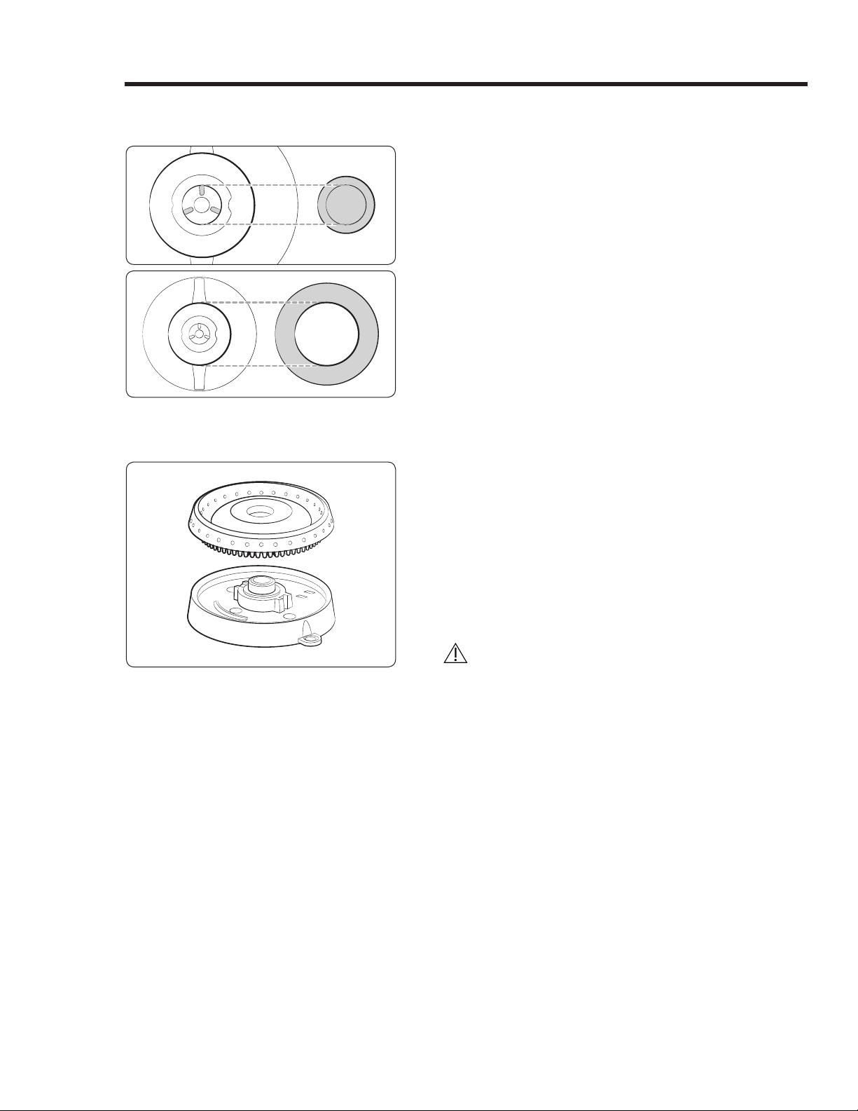
Dual Burner Head/Cap, cont.
3. Match the burner caps to the burners by size,
then install the caps on the heads.
Round Burner Head/Cap
1. Put the burner heads on the burner bases as
shown at left. The bottom of the head fits within
the burner base.
2. Turn the head until it drops into place. Twist the
head back and forth slightly to ensure it is
properly seated.
3. Put the burner caps (brass or porcelain) atop the
burner heads. The ridge around the bottom edge
of the cap fits around the top of the burner head.
CAUTION
Ensure all burner components (heads and caps) rest
flat and snugly in place.
Installation Instructions
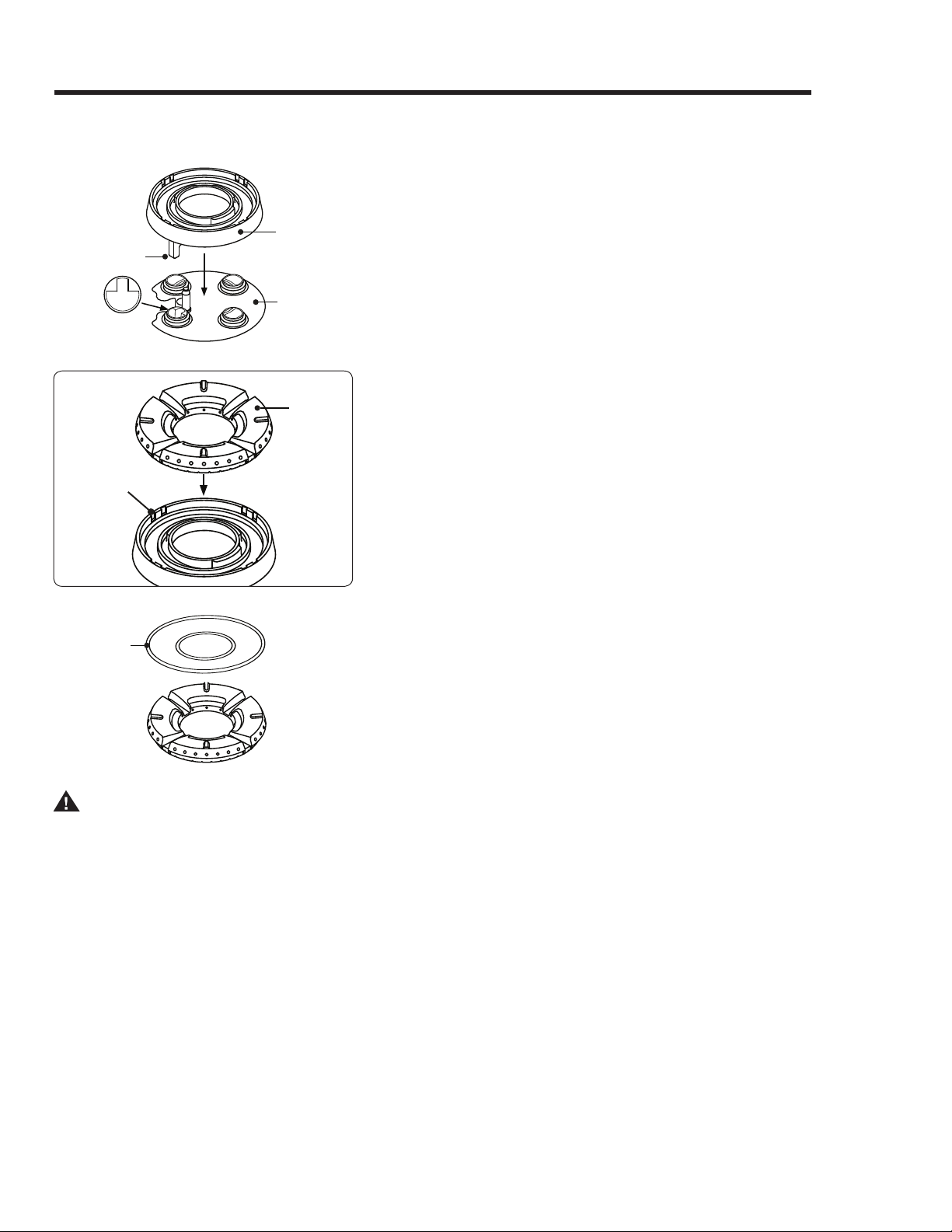
SimmerSear Assembly
Keyed Hole
Locating
Tab
Burner
Base
Burner
Head
1. Put the burner heads in place as shown. The
locating tab on the burner head goes in the keyed
hole as shown.
Tabs Slots
Burner
Ring
2. Put the burner rings on the burner heads as shown.
Match the tabs on the bottom of the ring to the
slots on the head. Twist each ring back and forth
slightly to verify it is properly seated.
Ridge on
Bottom of
Burner Cap
3. Put the burner caps on the burner rings. Use
either the supplied brass or porcelain caps. The
ridge around the bottom edge of the cap goes
around the top of the burner ring.
WARNING
Be sure electrical power is off and all surfaces are cool before cleaning any part of the cooktop.
32 English
English 33
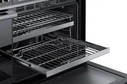
Installation Instructions
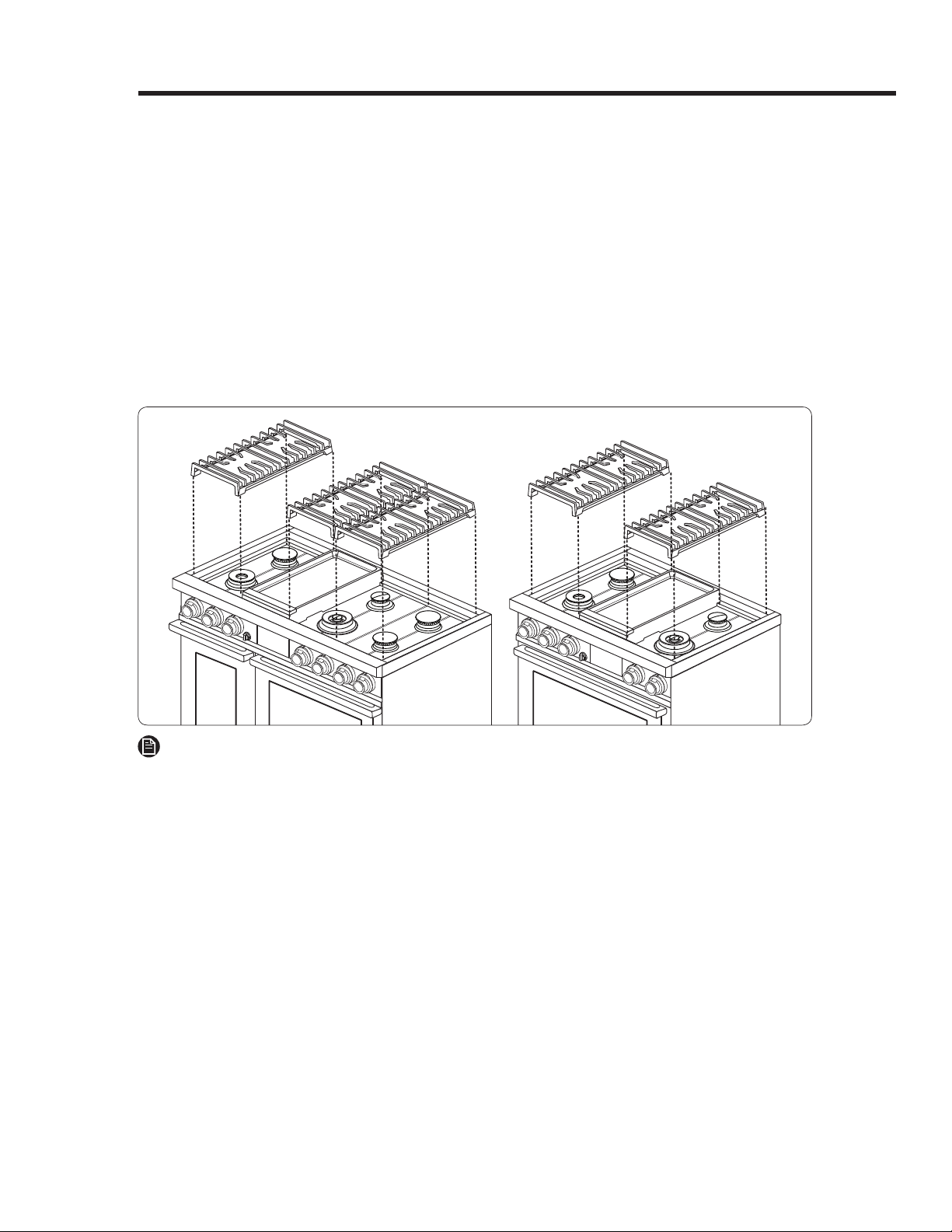
Installing the Grates
For best results and longest life, install the grates as instructed. When installed properly, the
openings in the grates are centered over the burners. The grates occupy specific positions on the
rangetop. For maximum stability and safe operation, these grates should only be used in their
proper positions. The back of the right grate is notched to help orient the grates correctly. (See the
graphic below.)
To correctly position the grates:
1. Find the notch on the back of the right-hand grate, and orient the grate properly above the
right-hand burners.
2. Gently lower the right-hand grate so its legs rest in the corresponding dimples on the cooktop.
3. Likewise place the remaining grates so their feet rest in the corresponding dimples.
NOTE
Grates are not interchangeable. Each grate has own engraving under it. It tells you which
the front side of grate is and proper position, left, center or right.
34 English
Installation Instructions
Verifying Proper Operation
1. Before starting the test procedure, turn off all burners, and see that all burner components and
grates are properly positioned.
2. Open the gas-supply valve, and check for gas leaks.
3. Turn on power to the range at the circuit breaker or fuse box.
4. Use the oven display to set user preferences and wireless network settings.
5. On the display, tap MENU > BAKE. (The default bake temperature should appear.)
6. Tap Start. In 3 minutes, open the door to see that the oven chamber is heating. (The display
should show BAKE and the preheating temperature.)
7. Tap OFF.
8. Push a knob in, and turn it counterclockwise to HIGH. (Within 4 seconds,
ignition occurs, and the igniter stops sparking. If ignition does not occur
as expected, turn off the knob, wait 5 minutes for the gas to dissipate,
then retry the test.
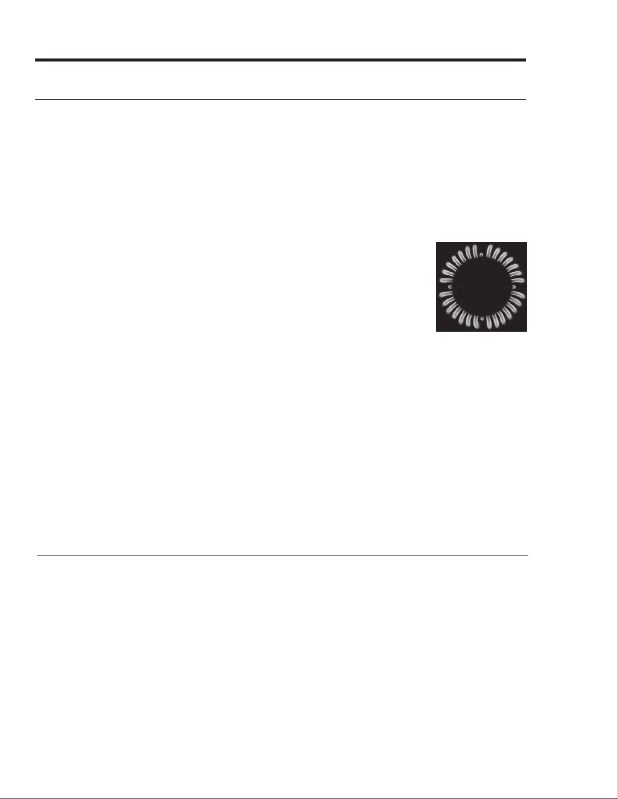
9. After ignition, turn the control knob from HIGH to LOW while watching
the flame height. If the range is installed properly, the flame is steady
and quiet with a sharp, blue inner cone that varies in length depending
on the burner size.
10. Turn the control knob OFF.
11. Repeat the ignition test for the remaining burners.
Normal Flame
If the range does not operate properly
:
1. Verify that power and gas are supplied to the range.
2. Check the electrical connections and gas supply to verify proper installation.
3. Repeat the above bake test and burner-ignition test.
4. If the range still does not work, contact Dacor Customer Assurance: (800) 793-0093 x2813. Be
ready with the model/serial numbers. (See the data label, left-side door trim.)
Do not try to repair the range yourself. Dacor is not responsible for the cost of correcting
problems caused by a faulty installation.
Removing and Reinstalling the Range
Removing the Range for Service
1. Close the gas-supply valve.
2. Turn off power to the range at the circuit breaker or fuse box.
3. Pull the range out from the wall
Reinstalling the Range After Service
1. Push the range into position, engaging the anti-tip bracket.
2. Turn on power to the range at the circuit breaker or fuse box.
3. Open the gas-supply valve.

English 35
InstalInstallation lation InstructionInstructionss
Installation Checklist
WARNING
The installer should complete this checklist to ensure thorough, proper installation.
Proper installation is the responsibility of the homeowner.
•
•
•
•
•
•
•
•
•
•
•
Was the plastic sheeting peeled off the range exterior?
Was all packaging removed from the oven chamber?
Do all leveling legs contact the floor? Is the unit level? (Pg. 27.)
Was the range secured with the anti-tip bracket and foot as instructed? (Pgs. 20 – 23.)
Was the gas-supply inlet pressure measured to ensure it does not exceed the maximums
stated in these instructions. (Pg. 18.)
Is the range connected to the gas supply as instructed and according to applicable codes? Was
the gas supply checked for leaks? Was the regulator cover re-installed? (Pg. 25 – 27.)
Is the oven door installed as instructed? (Pg. 28 – 29.)
Were the burner knobs properly installed? (Pg. 29.)
Are the burners (Pg. 30 – 32) and grates (Pg. 33) installed as instructed?
Was proper operation verified?
Was the warranty activated online or the warranty card filled out and mailed?

Dacor ∙ 14425 Clark Avenue, City of Industry, CA 91745 ∙ Phone: (800) 793-0093 ∙ Fax: (626) 403-3130 ∙ www.dacor.com
DG68-00936A-00