Loading ...
Loading ...
Loading ...
Mr. Heater MH4GC Golf Cart Heater Operating Instructions and OwnerÊs Manual
4
2015 CB
A slight yellow flame may occur where the pilot flame
and main burner flame meet. The burner should be bright
orange (with a slight blue color around the border, a red-
orange haze that is visible on the ceramic tile is acceptable)
and without a noticeable flame.
A blue flame that rolls out at the top of the ceramic tile
indicates an accumulation of dust, lint or spider webs
inside the housing assembly and main burner assembly.
If the pilot is yellow or the burner has a noticeable flame,
cleaning may be required. Use the following procedure to
inspect the casing assembly and main burner assembly. It
is necessary to periodically check the burner orifice and
burner venturi to make sure that they are clear of insects/
nests or spider webs that may accumulate over time. A
clogged tube can lead to a fire.
CLEANING INSTRUCTIONS:
1. Allow heater to thoroughly cool before performing
any maintenance.
2. Remove disposable 1 lb. propane cylinder from
heater.
3. Remove right side plastic service panel (Parts diagram
ref. 4) by removing the four screws holding it in
place.
4. Inspect the interior of casing for accumulation of
dust, lint or spider webs. If necessary, clean the
interior of the casing assembly with a vacuum cleaner
or compressed air (max 30 psi). Do not damage any
components within the casing assembly when you
are cleaning.
5. Inspect and clean main burner (Parts Diagram ref. 3)
and orifice (ref. 8) by using a vacuum or compressed
air (max 30 psi).
6. Inspect and clean pilot tube (Parts Diagram ref.
7). Insert a doubled over pipe cleaner into the
pilot tube until it bottoms against the pilot orifice
(approximately 2‰). Rotate the pipe cleaner a couple
of times and remove. Blow out the remaining debris
using compressed air.
LIGHTING / OPERATING INSTRUCTIONS
WARNING: Always inspect propane cylinder and heater
propane connections for damage, dirt, and debris before
attaching propane cylinder. Do not use if head of cylinder is
damaged, punctured or deteriorated.
ALWAYS ATTACH OR DETACH CYLINDER OUTDOORS AWAY
FROM FLAMES, OTHER IGNITION SOURCES, AND ONLY
WHEN HEATER IS COOL TO TOUCH. NEVER SMOKE WHEN
ATTACHING OR REMOVING PROPANE CYLINDER!
• LP cylinders must be marked in accordance with
„Cylinders, Spheres and Tubes for Transporation of
Dangerous Goods, CAN/CSA B339‰.
• Use only LP-gas cylinders marked in accordance with the
U.S. Dept. of Transportation (DOT).
• Use only 16.4 oz. (1 lb.) disposable cylinders that mate
with No. 600 valve connection.
• Heater and attached cylinder must be in an upright
position during operation.
• Screw 1 lb. disposable LP-gas supply cylinder clockwise
(from bottom) into portable heater until hand-tight and
fit cylinder into cup adapter. Do not use thread sealant
on this connection. Be sure cup adapter fits tightly into
cup holder before moving.
• Check cylinder connection for leaks with soapy water
at the threaded connection under the domed plastic
cover where the cylinder screws into the regulator. SEE
WARNING! ON PLASTIC COVER.
• Depress „ON‰ button to light pilot flame (repeat until
pilot lights) and continue to hold for 30-60 seconds.
• After lighting pilot, release „ON‰ button to light heater.
The white tile will take a few moments to start to glow.
• To shut off heater, press the „OFF‰ button.
• CAUTION: After turning heater off, wire guard will
remain hot. Allow to thoroughly cool before storing.
• Do not operate, store or remove cylinder near
flammable items or ignition sources.
• LP-GAS CYLINDERS MUST BE DISCONNECTED FROM
HEATER WHEN NOT IN USE!
• Heater must not be exposed to flammable vapors or
liquids during ignition or operation.
MAINTENANCE:
Always keep the heater area clear and free from
combustible materials, gasoline and other flammable
vapors and liquids.
Keep the vent areas (slots in the bottom and top of the
heater) clear at all times.
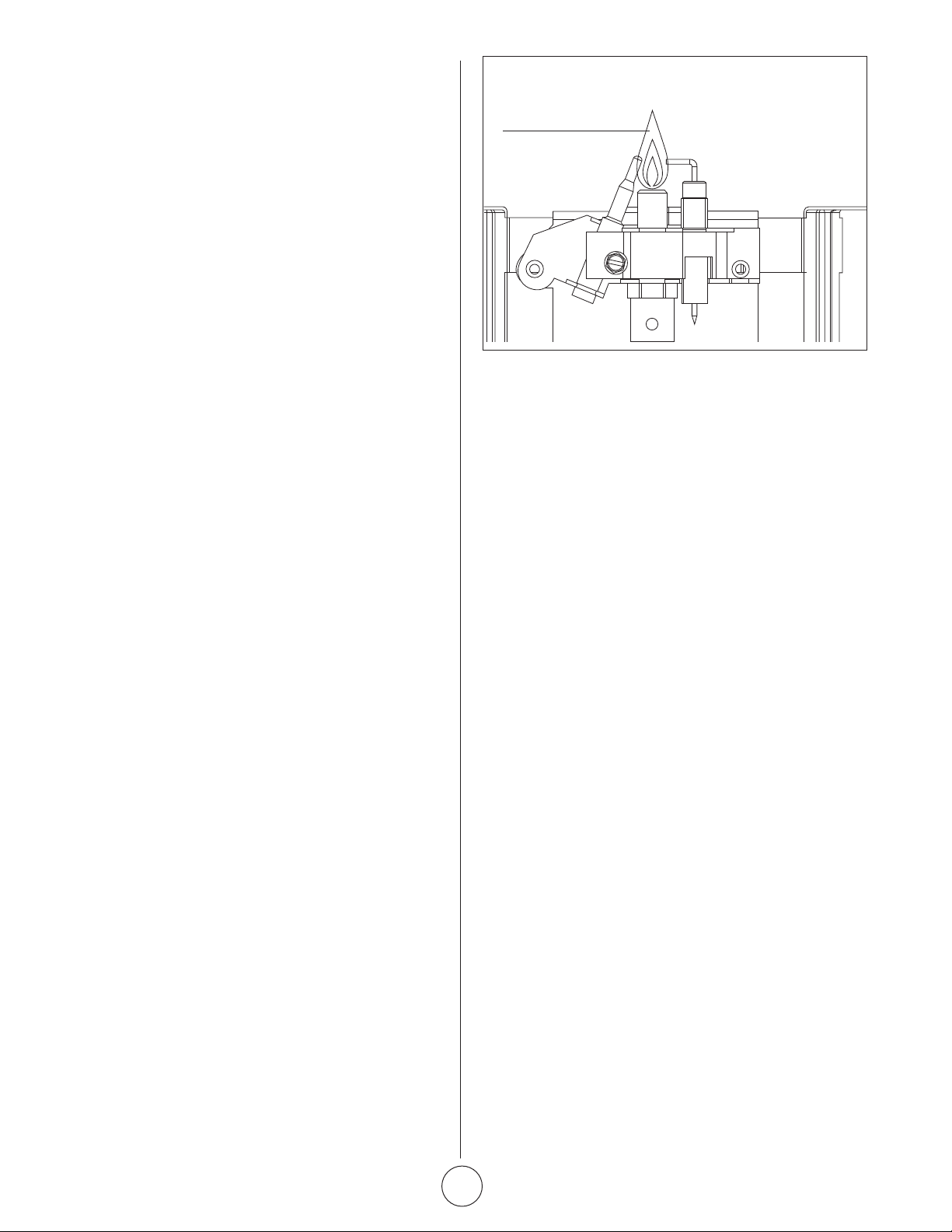
Visually inspect the pilot flame and burner periodically
during use. The pilot flame should be blue in color (not
yellow) and will extend to the thermocouple. The flame will
surround the thermocouple just below the tip, see Figure 2.
Pilot Flame
Oxygen Depletion Sensor
Figure 2
Loading ...
Loading ...
Loading ...