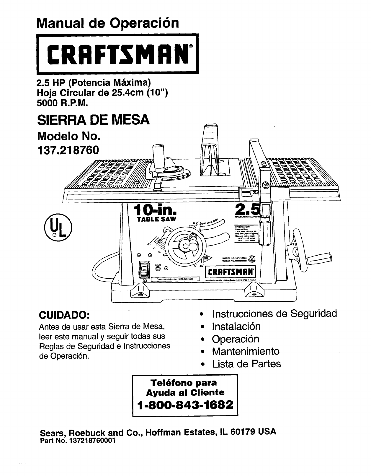
Owner's Manual
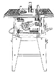
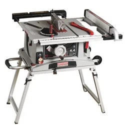
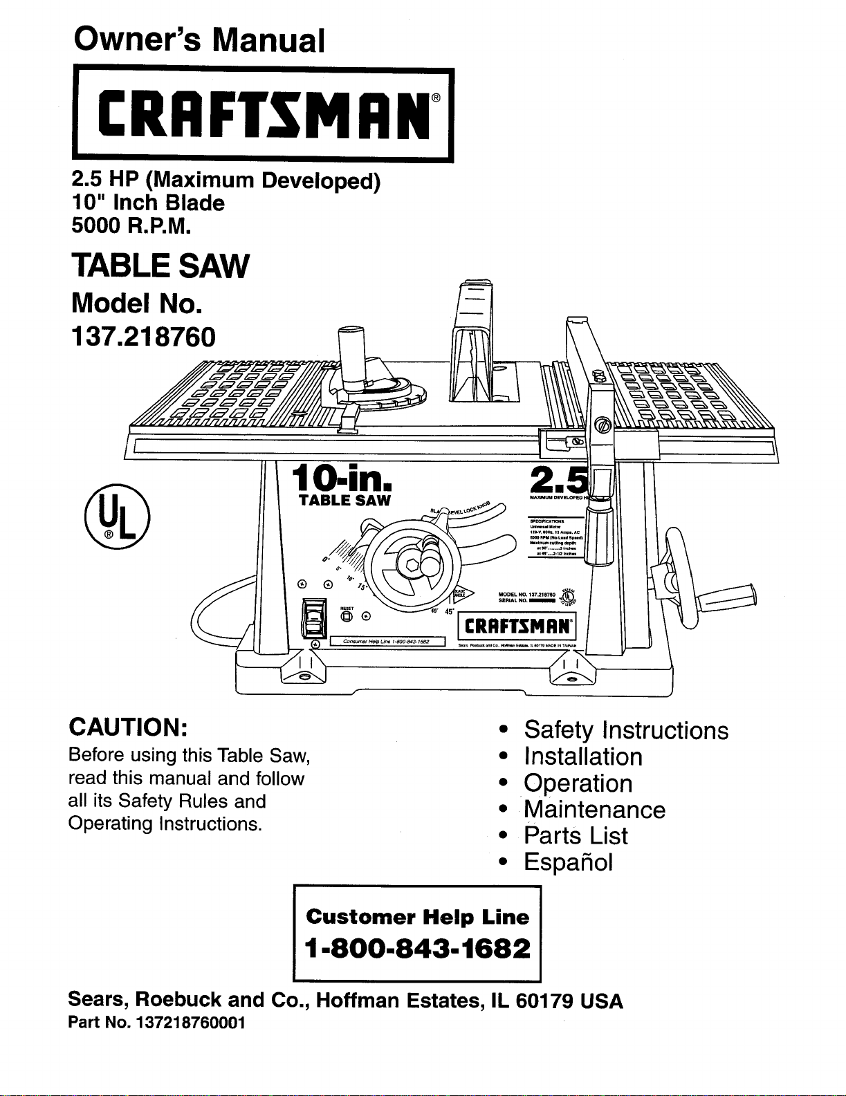
2.5 HP (Maximum Developed)
10" Inch Blade
5000 R.P.M.
TABLE SAW
Model No.
137.218760_
CAUTION:
Before using this Table Saw,
read this manual and follow
all its Safety Rules and
Operating Instructions.
• Safety Instructions
• Installation
• Operation
• Maintenance
• Parts List
• EspaSol
Customer Help Line
1-800-843-1682
Sears, Roebuck and Co., Hoffman Estates, IL 60179 USA
Part No. 137218760001
SECTION PAGE
Warranty ................................................................ 2
Product Specifications ..................................................... 2
Safety Instructions ......................................................... 3
Accessories and Attachments ............................................... 6
Tools needed for assembly ................................................. 6
Carton Contents .......................................................... 6
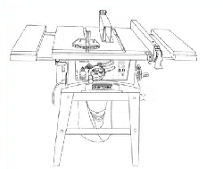
Know Your Table Saw ...................................................... 8
Assembly and Adjustments ................................................. 9
Operation .............................................................. 14
Maintenance ............................................................ 18
Troubleshooting guide .................................................... 19
Parts .................................................................. 20
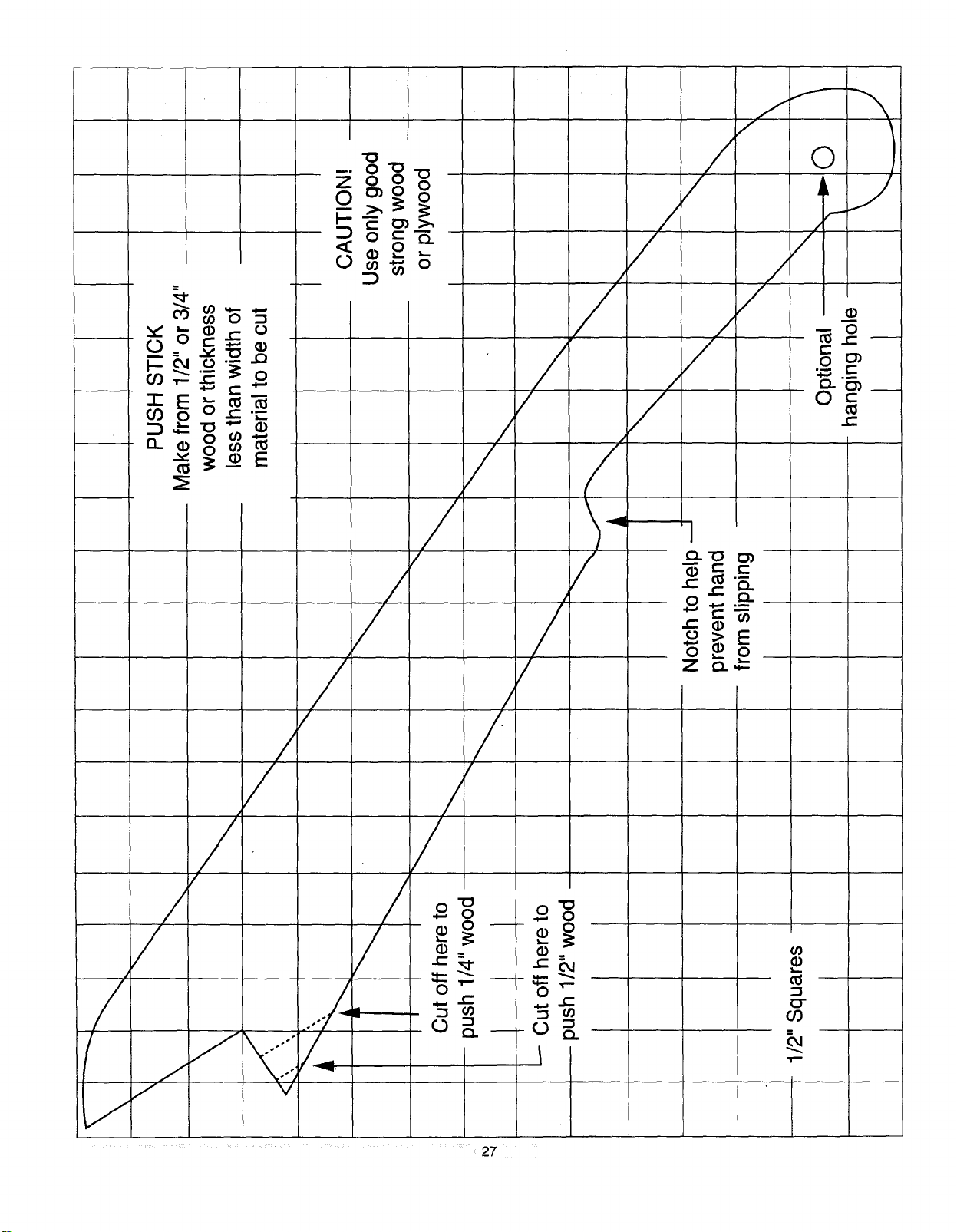
Making a push stick ...................................................... 27
Espafiol ................................................................ 31
FULL ONE YEAR WARRANTY
If this product fails due to a defect in material or workmanship within one year from the date of purchase, Sears
will repair it free of charge.
Contact a Sears Service Center for repair.
If this product is used for commercial or rental purposes, this warranty applies only for 90 days from the date of
purchase.
This warranty gives you specific legal rights, and you may also have other rights which vary from state to state.
Sears, Roebuck and Co., Dept. 817 WA, Hoffman Estates, IL 60179
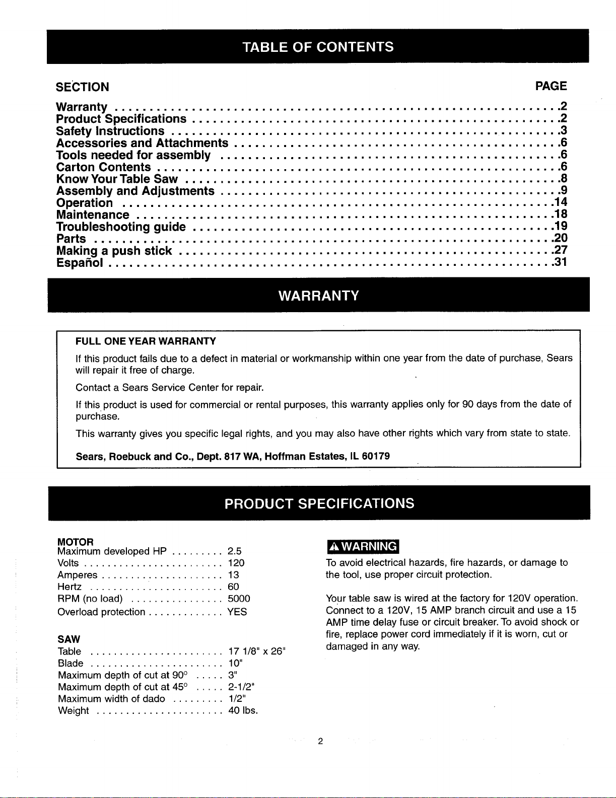
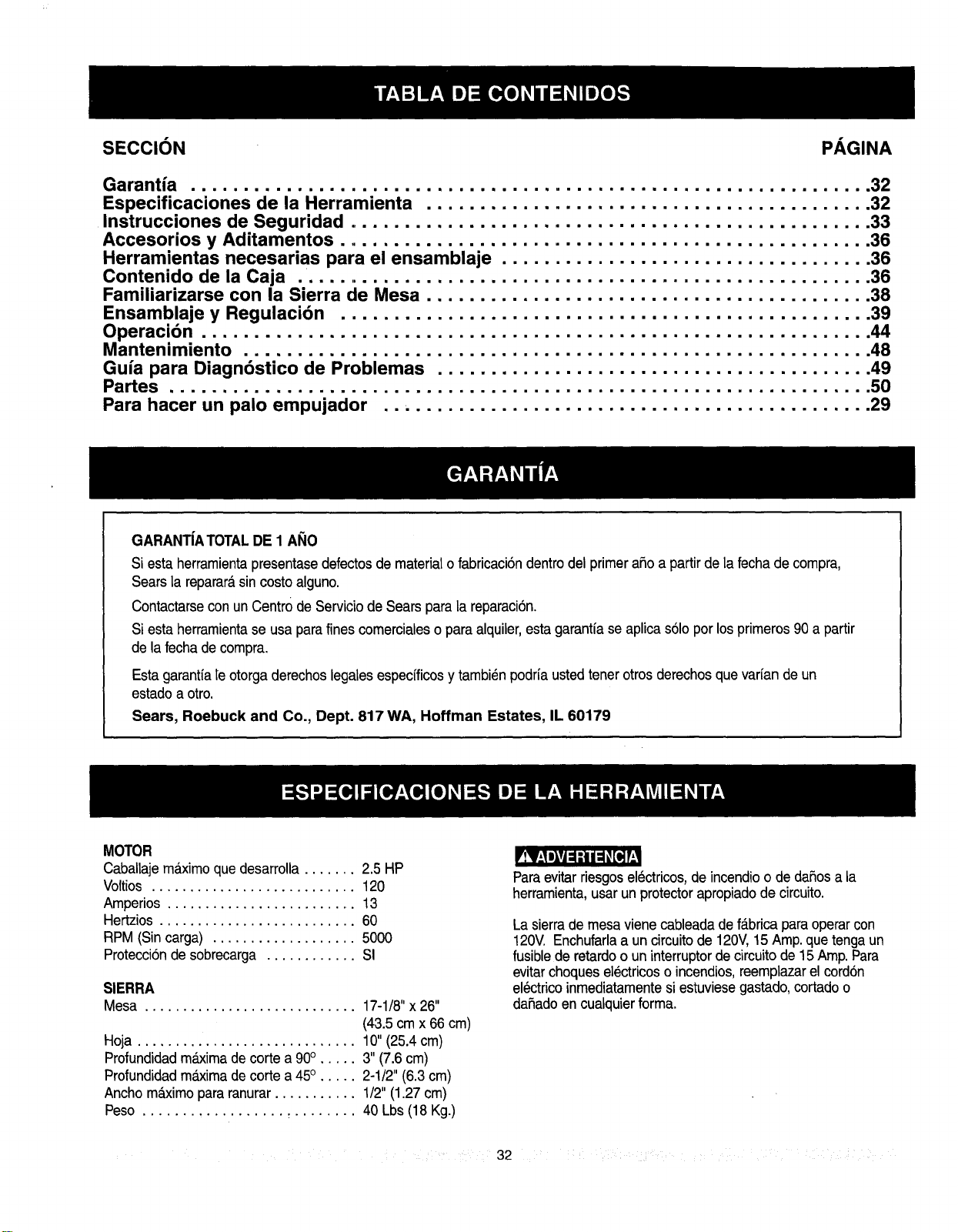
MOTOR
Maximum developed HP ......... 2.5
Volts ........................ 120
Amperes ..................... 13
Hertz ....................... 60
RPM (no load) ................ 5000
Overload protection ............. YES
SAW
Table ....................... 17 1/8" x 26"
Blade ....................... 10"
Maximum depth of cut at 90° ..... 3"
Maximum depth of cut at 45° ..... 2-1/2"
Maximum width of dado ......... 1/2"
Weight ...................... 40 Ibs.
To avoid electrical hazards, fire hazards, or damage to
the tool, use proper circuit protection.
Your table saw is wired at the factory for 120V operation.
Connect to a 120V, 15 AMP branch circuit and use a 15
AMP time delay fuse or circuit breaker. To avoid shock or
fire, replace power cord immediately if it is worn, cut or
damaged in any way.
GENERAL SAFETY INSTRUCTIONS
BEFORE USING THE TABLE SAW
Safety is a combination of common sense, staying alert
and knowing how to use your table saw.
To avoid mistakes that could cause serious injury, do not
plug the table saw in until you have read and understood
the following:
12.
1. READ and become familiar with this entire instruction
manual. LEARN the tool's applications, limitations, and
possible hazards. 13.
2. KEEP GUARDS IN PLACE and in working order.
14.
3. REMOVE ADJUSTING KEYS AND WRENCHES.
Form the habit of checking to see that keys and
adjusting wrenches are removed from the tool before
turning ON. 15.
4, KEEP WORK AREA CLEAN. Cluttered areas and
benches invite accidents.
DON'T USE IN A DANGEROUS ENVIRONMENT.
Don't use power tools in damp or wet locations, or
expose them to rain. Keep work area well lighted.
KEEP CHILDREN AWAY.All visitors should be kept at
a safe distance from the work area.
.
.
7. MAKE WORKSHOP KID PROOF with padlocks, master
switches, or by removing starter keys.
8. DON'T FORCE THE TOOL. It will do the job better
and safer at the rate for which itwas designed.
9. USE THE RIGHT TOOL. Don't force tool or the
attachment to do a job for which itwas not.designed.
10. USE PROPER EXTENSION CORD. Make sure your
extension cord is in good condition. When using an
extension cord, be sure to use one heavy enough to
carry the currentyour productwilldraw.An undersized
cord will cause a drop in line voltage resulting in loss
of power and overheating.The table on page 7 shows
the correct size to use depending on cord length and
nameplate ampere rating. If in doubt, use the next
heavier gauge. The smaller the gauge number, the
heavier the cord.
11. WEAR PROPER APPAREL. DO NOT wear loose
clothing, gloves, neckties, rings, bracelets, or other
jewelry which may getcaught in moving parts.
Nonslip footwear is recommended. Wear protective
hair covering to contain long hair.
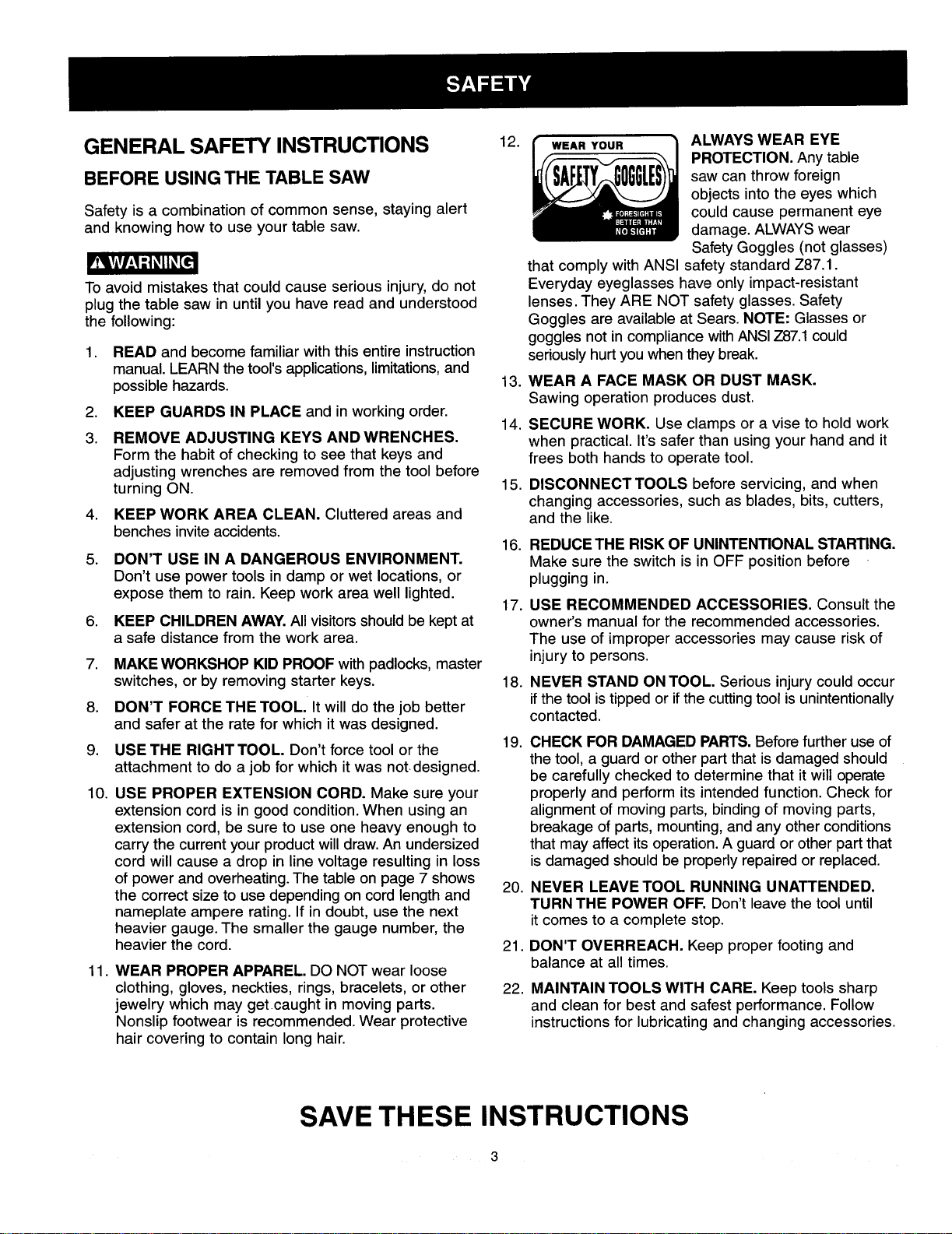
ALWAYS WEAR EYE
PROTECTION. Any table
saw can throw foreign
objects intothe eyes which
could cause permanent eye
damage. ALWAYS wear
Safety Goggles (not glasses)
that comply with ANSI safety standard Z87.1.
Everyday eyeglasses have only impact-resistant
lenses. They ARE NOT safety glasses. Safety
Goggles are available at Sears. NOTE: Glasses or
goggles not in compliance with ANSI Z87.1 could
seriously hurt you when they break.
WEAR A FACE MASK OR DUST MASK.
Sawing operation produces dust.
SECURE WORK. Use clamps or a vise to hold work
when practical. It's safer than using your hand and it
frees both hands to operate tool.
DISCONNECT TOOLS before servicing, and when
changing accessories, such as blades, bits, cutters,
and the like.
16. REDUCE THE RISK OF UNINTENTIONAL STARTING.
Make sure the switch is in OFF position before
plugging in.
17. USE RECOMMENDED ACCESSORIES. Consult the
owner's manual for the recommended accessories.
The use of improper accessories may cause risk of
injury to persons.
18. NEVER STAND ON TOOL. Serious injurycould occur
ifthe tool istipped or ifthe cuttingtool isunintentionally
contacted.
19.
20.
CHECK FOR DAMAGED PARTS. Before further use of
the tool, a guard or other part that is damaged should
be carefully checked to determine that it will operate
properly and perform its intended function. Check for
alignment of moving parts, bindingof moving parts,
breakage of parts, mounting,and any otherconditions
that may affect its operation.A guard or otherpart that
is damaged should be properly repaired or replaced.
NEVER LEAVE TOOL RUNNING UNATTENDED.
TURN THE POWER OFF. Don't leave the tool until
itcomes to a complete stop.
DON'T OVERREACH. Keep proper footingand
balance at all times.
MAINTAIN TOOLS WITH CARE. Keep tools sharp
and clean for best and safest performance. Follow
instructionsfor lubricating and changing accessories.
SAVE THESE INSTRUCTIONS

23. DIRECTION OF FEED. Feed work into a blade or cutter
against the directionof rotation of the blade or cutter
only.
24. WARNING: Dust generated from certain materials can
be injurious to your health. Always operate saw in well
ventilated areas and provide for proper dust removal.
SPECIFIC SAFETY INSTRUCTIONS
FOR THE TABLE SAW
,
ALWAYS USE SAW BLADE GUARD spreader and
anti-kickback pawls for every operation for which
they can be used, including through-sawing.
Through-sawing operations are those in which the
blade cuts completely through the workpiece
when ripping or cross-cutting.
2. ALWAYS HOLD THE WORK FIRMLY against the
miter gauge or rip fence.
.
USE A PUSH STICK when required. Always use a
push stick for ripping narrow stock. Refer to ripping
applications in the instruction manual where the
push stick iscovered in detail. See the push stick
pattern included in this Owner's Manual.
. NEVER PERFORM ANY OPERATION
"FREE HAND", which means using your hands
only to support or guide the workpiece. Always
use either the fence or the miter gauge to position
and guide the work.
5. NEVER STAND or have any part of your body
in line with the path of the saw blade. Keep your
hands out of the line of the saw blade.
6. NEVER REACH behind or over the cutting tool
for any reason.
7. REMOVE the rip fence when cross-cutting.
8. DO NOT USE molding head set with this saw.
9. FEED WORK INTO THE BLADE against the
direction of rotation only.
10. NEVER use the fence as a cut-off gauge when
cross-cutting.
rvA,W_t"_II_[¢
11. NEVER ATTEMPT TO FREE A STALLED SAW
BLADE without first turning the saw OFF. Turn
power switch OFF immediately to prevent motor
damage.
12. PROVIDE ADEQUATE SUPPORT to the rear and
sides of the saw table for wide or long workpieces.
13.
AVOID KICKBACKS (work thrown back towards
you) by keeping the blade sharp, keeping the rip
fence parallel to the saw blade, and by keeping the
spreader, anti-kickback pawls, and guard in place
and functioning. Do not release work before it is
pushed all the way past the saw blade. Do not rip
work that is twisted, warped, or does not have a
straight edge to guide along the fence.
14. AVOID AWKWARD OPERATIONS and hand
positions where a sudden slip could cause your
hand to move intothe cutting tool.
15.
NEVER USE SOLVENTS to clean plastic parts.
Solvents could possibly dissolve or otherwise
damage the material. Only a soft damp cloth should
be used to clean plastic parts.
16. MOUNT your table saw before performing any
cutting operations. Refer to installation instructions.
17. NEVER CUT METALS or materials which may make
hazardous dust.
18. ALWAYS USE IN A WELL VENTILATED AREA.
Remove sawdust frequently. Clean out sawdust from
the interiorof the saw to prevent a potential fire
hazard.
19. NEVER LEAVE THE TOOL running unattended.
Don't leave the tool until it comes to a complete stop.
20.
For proper operation follow the instructions of this
owner's manual titled "SAW MOUNTED TO WORK
SURFACES." Failure to provide sawdust fall-through
and removal hole will allow sawdust to build up in
the motor area, which may result in a fire hazard or
cause motor damage.
ELECTRICAL REQUIREMENTS
POWER SUPPLY AND MOTOR
SPECIFICATIONS
To avoid electrical hazards, fire hazards, or damage to
the tool, use proper circuit protection. Use a separate
electrical circuit for your tools.Your saw is wired at the
factory for 120V operation. Connect to a 120V, 15 Amp
circuit and use a 15 Amp time delay fuse or circuit
breaker. To avoid shock or fire, if power cord is worn or
cut, or damaged in any way, have it replaced
immediately.
SAVE THESE INSTRUCTIONS
4
GROUNDING INSTRUCTIONS
INTHE EVENT OF A MALFUNCTION OR BREAKDOWN,
grounding provides a path of least resistance for electric
current and reduces the risk of electric shock.This tool
is equipped with an electric cord that has an equipment
grounding conductor and a grounding plug.The plug
MUST be plugged into a matching receptacle that is
properly installed and grounded in accordance with ALL
local codes and ordinances.
DO NOT MODIFY THE PLUG PROVIDED. If it will not
fit the receptacle, have the proper receptacle installed
by a qualified electrician.
IMPROPER CONNECTION of the equipment grounding
conductor can result in risk of electric shock.The
conductor with the green insulation (with or without
yellow stripes) isthe equipment grounding conductor. If
repair or replacement of the electric cord or plug is
necessary, DO NOT connect the equipment grounding
conductor to a live terminal.
CHECK with a qualified electrician or service person if
you do not completely understand the grounding
instructions,or ifyou are not sure the toolis properly
grounded.
USE A SEPARATE ELECTRICAL CIRCUIT for your
tools. This circuit must not be less than #12 wire and
should be protected with a 15 Amp time delay fuse.
Before connecting the motor to the power line, make
sure the switch is in the OFF position and the electric
current is rated the same as the current stamped on the
motor nameplate. Running at a lower voltage will
damage the motor.
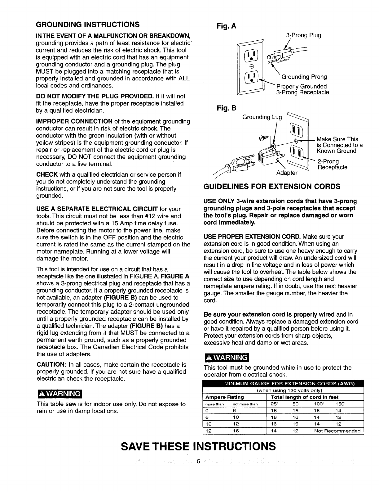
This tool is intended for use on a circuit that has a
receptaclelike the one illustratedin FIGURE A. FIGURE A
shows a 3-prong electrical plug and receptacle that has a
groundingconductor.Ifa properly grounded receptacle is
not available, an adapter (FIGURE B) can be used to
temporarily connect this plug to a 2-contact ungrounded
receptacle. The temporary adapter should be used only
until a properly grounded receptacle can be installed by
a qualified technician.The adapter (FIGURE B) has a
rigid lug extending from itthat MUST be connected to a
permanent earth ground, such as a properly grounded
receptacle box. The Canadian Electrical Code prohibits
the use of adapters.
r_k_v/_[-.._ll_[_
CAUTION: In all cases, make certain the receptacle is
properly grounded. If you are not sure have a qualified
electrician check the receptacle.
IITAII_IILVILIJ_I[_ LS[O]Zl I_['4Btl::l_[,,,,'][0]_1 [o,][o_,]=]Lm,3_][_]
rv_l,VlVl_,_--1_,II_[e
This table saw is for indoor use only. Do not expose to
rain or use in damp locations.
Fig. A
3-Prong Plug
_ pr_i_el;d_go_iing e
Fig. B
Grounding Lug
_ Make Sure This
is Connected to a
Known Ground
"_ 2-Prong
Receptacle
GUIDELINES FOR EXTENSION CORDS
USE ONLY 3-wire extension cords that have 3-prong
grounding plugs and 3-pole receptacles that accept
the tool's plug. Repair or replace damaged or worn
cord immediately.
USE PROPER EXTENSION CORD. Make sure your
extension cord is in good condition.When usingan
extension cord, be sure to use one heavy enough to carry
the current your productwill draw.An undersizedcord will
result in a drop in linevoltage and in loss of power which
willcause the toolto overheat.The table below shows the
correctsize to use depending on cord length and
nameplate ampere rating.If in doubt, use the next heavier
gauge. The smaller the gauge number,the heavierthe
cord.
Be sure your extension cord is properly wired and in
good condition.Always replace a damaged extension cord
or have itrepaired by a qualified person before using it.
Protect yourextension cordsfrom sharp objects,
excessive heat and damp or wet areas.
This tool must be grounded while in use to protect the
operator from electrical shock.
(when using 120 volts only)
Ampere Rating Total length of cord in feet
more than not more than 25' 50' 100' 1SO'
0 6 18 16 16 14
6 10 18 16 14 12
10 12 16 16 14 12
12 16 14 12 Not Recommended
SAVE THESE INSTRUCTIONS
5
RECOMMENDED ACCESSORIES
Visit your Sears Hardware Department or see the
Craftsman Power and Hand Tools Catalog to purchase
recommended accessories for this power tool.
UNPACKING AND CHECKING CONTENTS
Separate all parts from packing material. Check each one
with the illustration on the next page and the table of
loose parts to make certain all items are accounted for,
before discarding any packing material.
To avoid the risk of personal injury:
• Do not use adjustable (wobble) type dadoes or
carbide tipped dado blades, maximum dado width
is 1/2".
• Do not use a dado with a diameter larger than 6".
• Do not use molding head set with this saw.
• Do not modify this power tool or use accessories not
recommended by Sears.
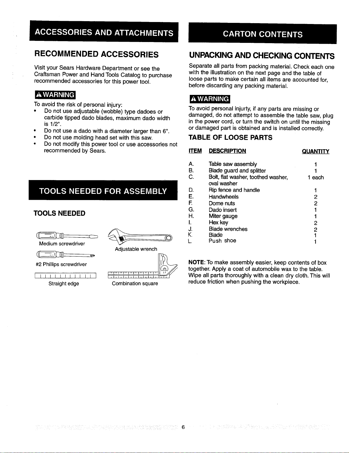
TOOLS NEEDED
Medium screwdriver
Adjustable wrench
#2 Phillipsscrewdriver
I I Ill I till I I ] t'_'_'°i'_:_'_i4"_i_",, , , , ,
Straight edge Combination square
To avoid personal injurty, if any parts are missing or
damaged, do not attempt to assemble the table saw, plug
in the power cord, or turn the switch on untilthe missing
or damaged part is obtained and is installed correctly.
TABLE OF LOOSE PARTS
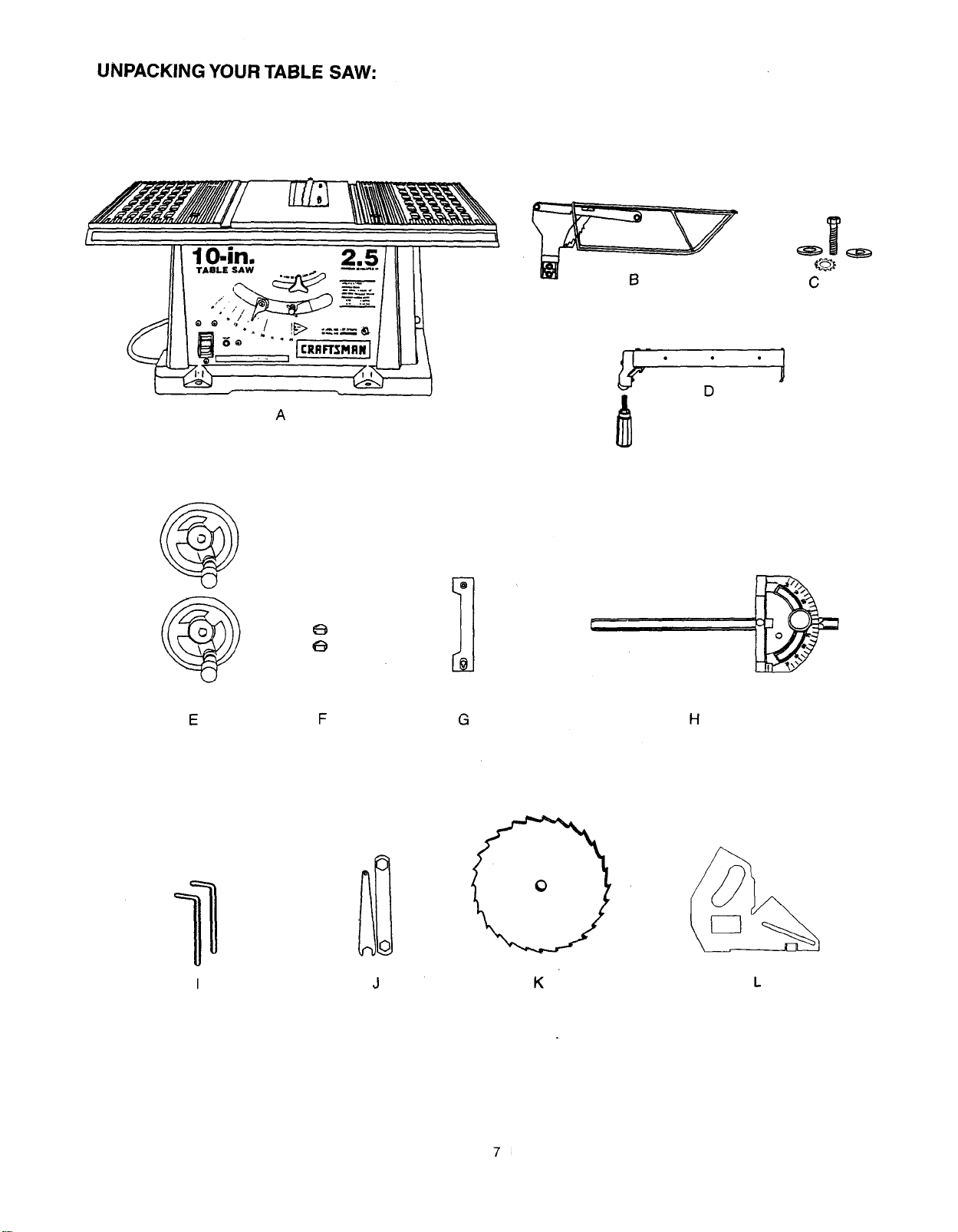
ITEM DESCRIPTION QUANTITY
A. Table saw assembly 1
B. Blade guard and splitter 1
C. Bolt, flat washer, toothed washer, 1 each
oval washer
D. Rip fence and handle 1
E. Handwheels 2
E Dome nuts 2
G. Dado insert 1
H. Miter gauge 1
I. Hex key 2
J. Blade wrenches 2
K. Blade 1
L. Push shoe 1
NOTE: To make assembly easier, keep contents of box
together. Apply a coat of automobile wax to the table.
Wipe all parts thoroughly with a clean dry cloth.This will
reduce friction when pushing the workpiece.
6
UNPACKING YOUR TABLE SAW:
A
C
e
e
1
G
H
K
L
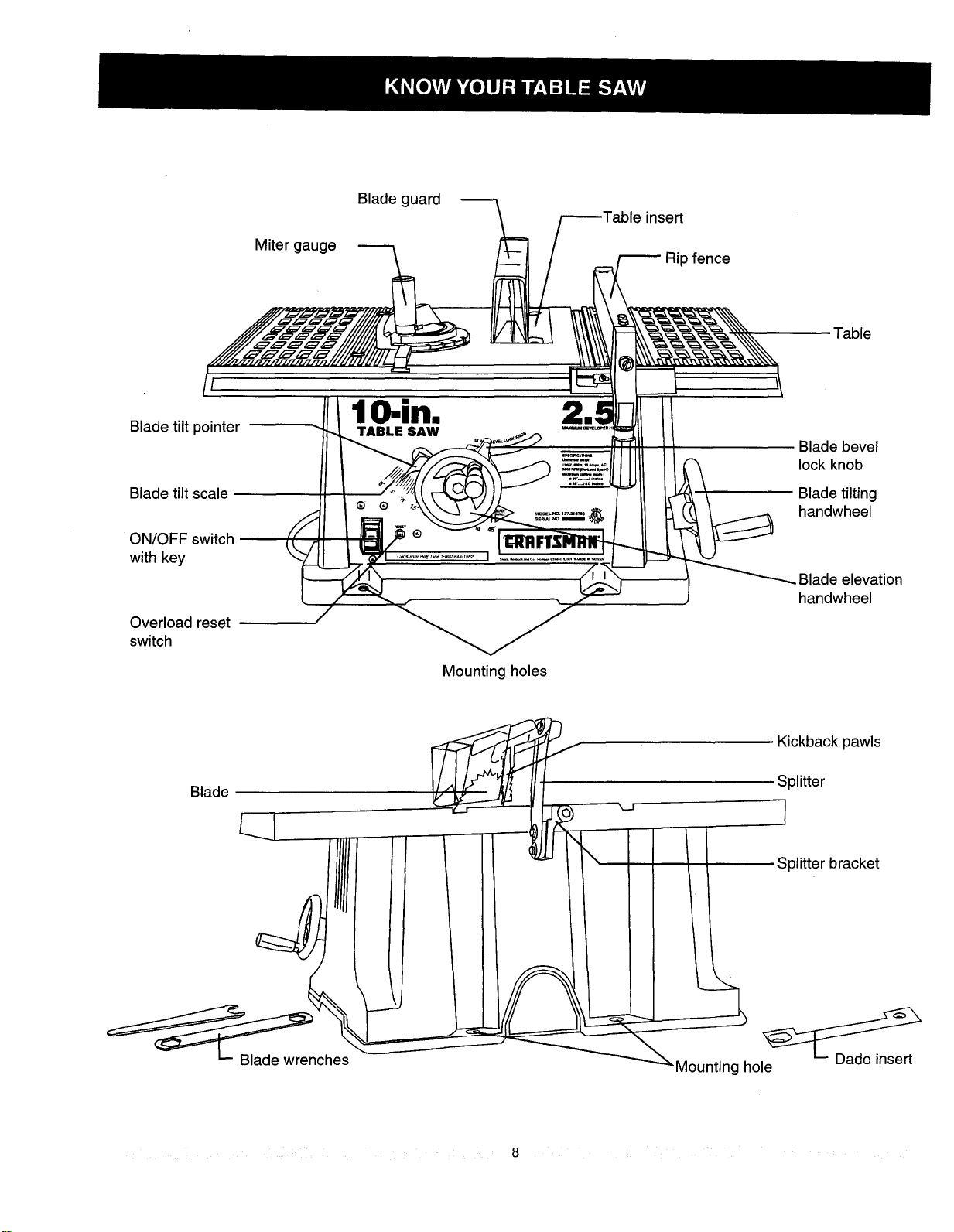
Miter gauge
Blade guard
.=insert
Rip fence
/
Blade tilt pointer
l in.
TABLE SAW
Table
Blade tilt scale
ON/OFF switch
with key
Overload reset
switch
Blade bevel
lock knob
Blade tilting
handwheel
Blade elevation
handwheel
Mounting holes
Blade
.J
Kickback pawls
Splitter
€ plitter bracket
_nches
Mounting hole
8
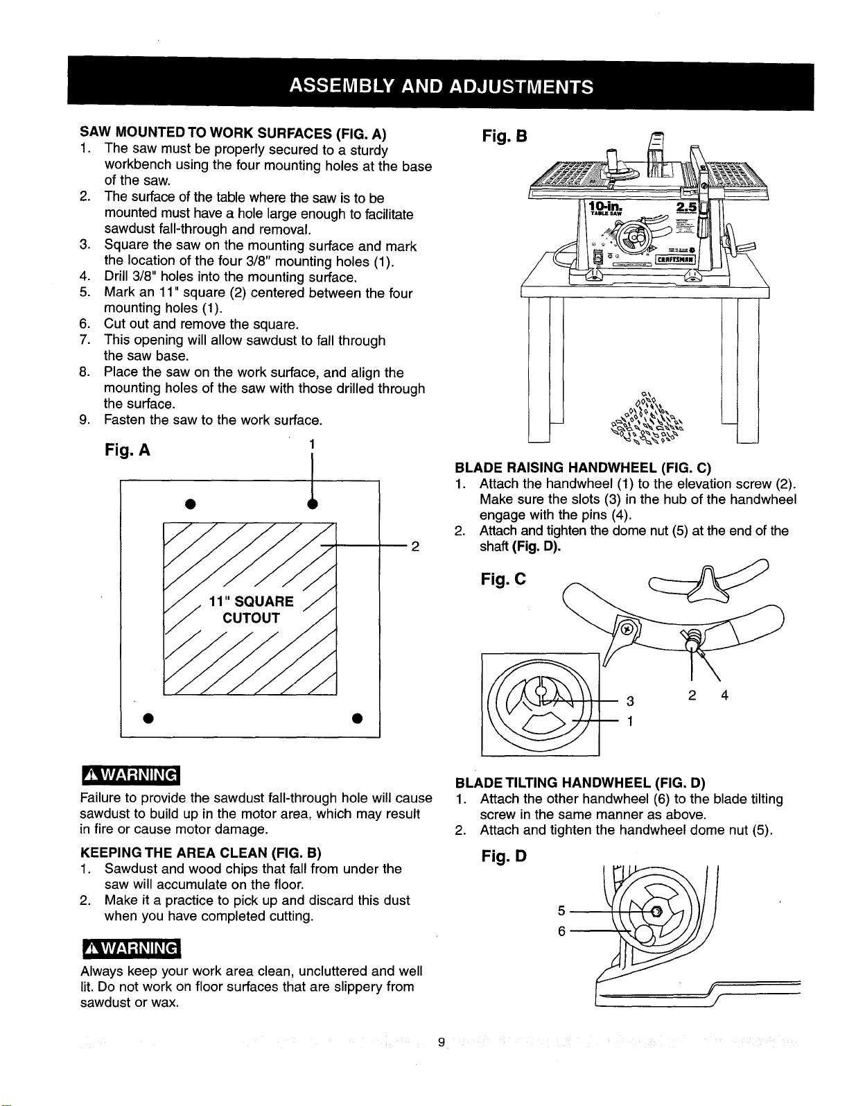
SAW MOUNTED TO WORK SURFACES (FIG. A)
1. The saw must be properly secured to a sturdy
workbench using the four mounting holes at the base
of the saw.
2. The surface of the table where the saw is to be
mounted must have a hole large enough to facilitate
sawdust fall-through and removal.
3. Square the saw on the mounting surface and mark
the location of the four 3/8" mounting holes (1).
4. Drill 3/8" holes intothe mounting surface.
5. Mark an 11" square (2) centered between the four
mounting holes (1).
6. Cut out and remove the square.
7. This opening will allow sawdust to fall through
the saw base.
8. Place the saw on the work surface, and align the
mounting holes of the saw with those drilled through
the surface.
9. Fasten the saw to the work surface.
Fig. A
1
l
2
Fig. B
BLADE RAISING HANDWHEEL (FIG. C)
1. Attach the handwheel (1) to the elevation screw (2).
Make sure the slots (3) in the hub of the handwheel
engage with the pins (4).
2. Attach and tightenthe dome nut (5) at the end ofthe
shaft (Fig. D).
Fig. C
3 2 4
1
P_Eig'Zld_l_€
Failure to provide the sawdust fall-through hole will cause
sawdust to build up in the motor area, which may result
in fire or cause motor damage.
KEEPING THE AREA CLEAN (FIG. B)
1. Sawdust and wood chips that fall from under the
saw will accumulate on the floor.
2. Make it a practice to pick up and discard this dust
when you have completed cutting.
Always keep your work area clean, uncluttered and well
lit. Do not work on floor surfaces that are slippery from
sawdust or wax.
BLADE TILTING HANDWHEEL (FIG. D)
1. Attach the other handwheel (6) to the blade tilting
screw in the same manner as above.
2. Attach and tighten the handwheel dome nut (5).
Fig. D
9
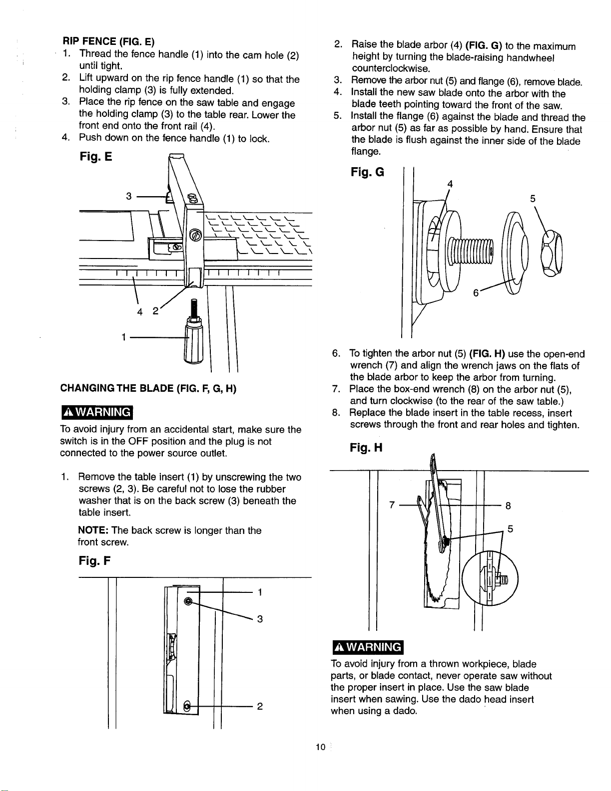
RIP FENCE (FIG. E)
1. Thread the fence handle (1) into the cam hole (2)
until tight.
2. Lift upward on the rip fence handle (1) so that the
holding clamp (3) is fully extended.
3. Place the rip fence on the saw table and engage
the holding clamp (3) to the table rear. Lower the
front end onto the front rail (4).
4. Push down on the fence handle (1) to lock.
Fig. E
I I I I I I
4
I I I I
CHANGING THE BLADE (FIG. F, G, H)
To avoid injury from an accidental start, make sure the
switch is in the OFF position and the plug is not
connected to the power source outlet.
.
Remove the table insert (1) by unscrewing the two
screws (2, 3). Be careful not to lose the rubber
washer that is on the back screw (3) beneath the
table insert.
NOTE: The back screw is longer than the
front screw.
Fig. F
1
_3
2
2. Raise the blade arbor (4) (FIG. G) to the maximum
height by turning the blade-raising handwheel
counterclockwise.
3. Remove the arbor nut (5) and flange (6), remove blade.
4. Install the new saw blade onto the arbor with the
blade teeth pointing toward the front of the saw.
5. Install the flange (6) against the blade and thread the
arbor nut (5) as far as possible by hand. Ensure that
the blade is flush against the inner side of the blade
flange.
Fig. G
5
6. To tighten the arbor nut (5) (FIG. H) use the open-end
wrench (7) and align the wrench jaws on the flats of
the blade arbor to keep the arbor from turning.
7. Place the box-end wrench (8) on the arbor nut (5),
and turn clockwise (to the rear of the saw table.)
8. Replace the blade insert in the table recess, insert
screws through the front and rear holes and tighten.
Fig. H
7
8
5
To avoid injury from a thrown workpiece, blade
parts, or blade contact, never operate saw without
the proper insert in place. Use the saw blade
insert when sawing. Use the dado head insert
when using a dado.
10
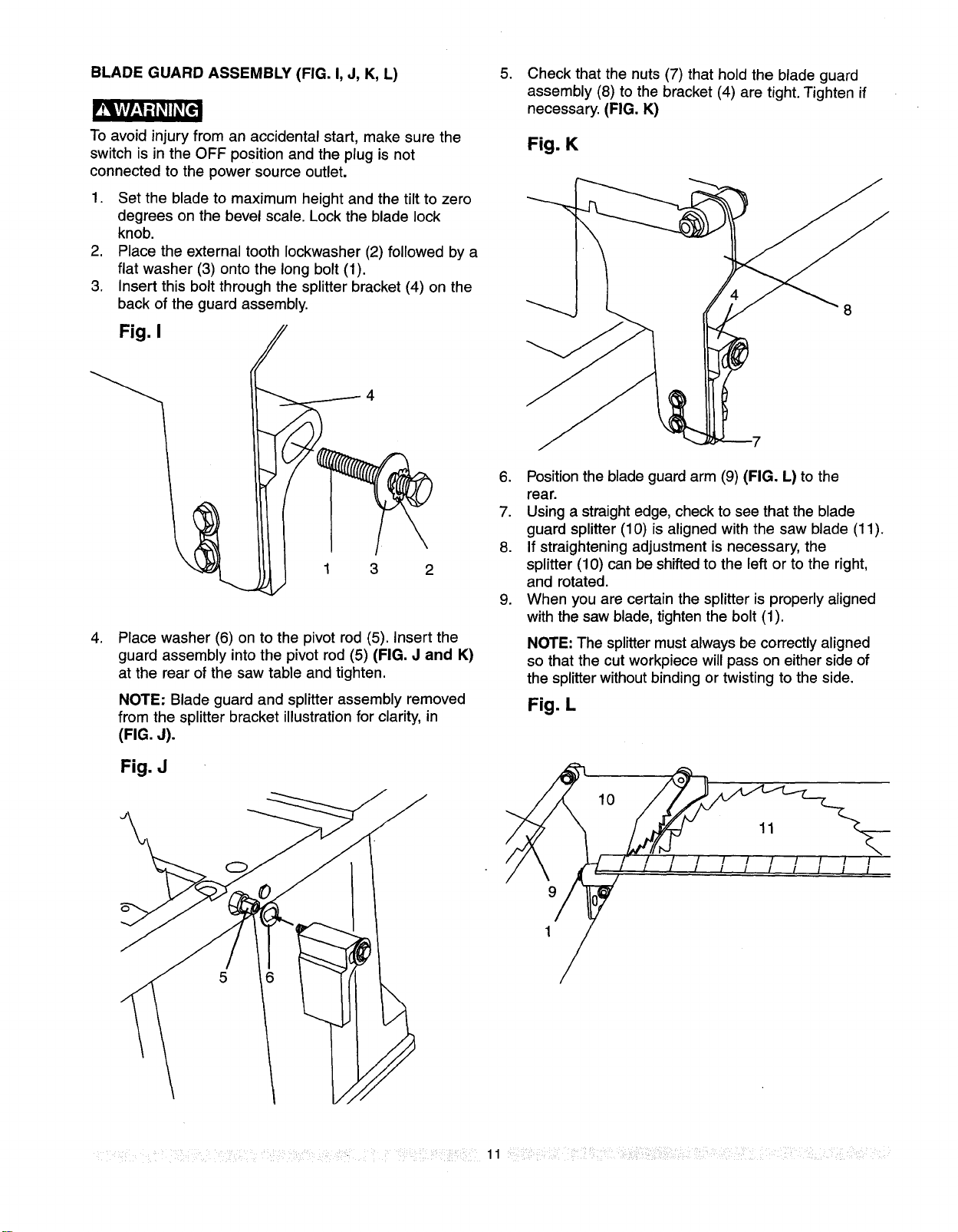
BLADE GUARD ASSEMBLY (FIG. I, J, K, L)
To avoid injury from an accidental start, make sure the
switch is in the OFF position and the plug is not
connected to the power source outlet.
1. Set the blade to maximum height and the tilt to zero
degrees on the bevel scale. Lock the blade lock
knob.
2. Place the external tooth Iockwasher (2) followed by a
flat washer (3) onto the long bolt (1).
3. Insert this bolt through the splitter bracket (4) on the
back of the guard assembly.
Fig. I
3 2
.
Place washer (6) on to the pivot rod (5). Insert the
guard assembly into the pivot rod (5) (FIG. J and K)
at the rear of the saw table and tighten.
NOTE: Blade guard and splitter assembly removed
from the splitter bracket illustration for clarity, in
(FIG. J).
Fig. J
.
Check that the nuts (7) that hold the blade guard
assembly (8) to the bracket (4) are tight. Tighten if
necessary. (FIG. K)
Fig. K
6. Position the blade guard arm (9) (FIG. L) to the
rear.
7. Using a straight edge, check to see that the blade
guard splitter (10) is aligned with the saw blade (11).
8. If straightening adjustment is necessary, the
splitter (10) can be shifted to the left or to the right,
and rotated.
9. When you are certain the splitter is properly aligned
with the saw blade, tighten the bolt (1).
NOTE: The splitter must always be correctly aligned
so that the cut workpiece will pass on either side of
the splitter without binding or twisting to the side.
Fig. L
10
11
I
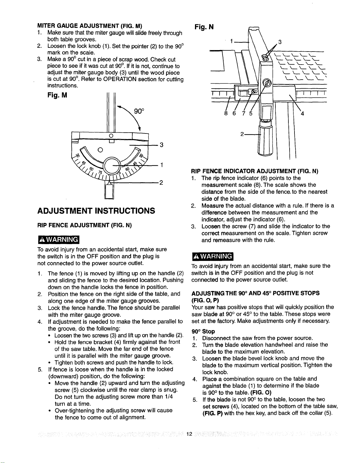
MITER GAUGE ADJUSTMENT (FIG. M)
1. Make sure that the mitergauge willslidefreely through
both table grooves.
2. Loosen the lock knob (1). Set the pointer(2) to the 90°
mark on the scale.
3. Make a 90° cut in a piece of scrap wood. Check cut
piece to see if itwas cut at 90°. If itis not, continueto
adjustthe miter gauge body (3) untilthe wood piece
is cut at 90°. Refer to OPERATION section for cutting
instructions.
Fig. M
° o 1_3
2
ADJUSTMENT INSTRUCTIONS
RIP FENCE ADJUSTMENT (FIG. N)
To avoid injury from an accidental start, make sure
the switch is in the OFF position and the plug is
not connected to the power source outlet.
1. The fence (1) is moved by lifting up on the handle (2)
and sliding the fence to the desired location. Pushing
down on the handle locks the fence in position.
2. Position the fence on the right side of the table, and
along one edge of the miter gauge grooves.
3. Lock the fence handle. The fence should be parallel
with the miter gauge groove.
4. If adjustment is needed to make the fence parallel to
the groove, do the following:
• Loosenthe two screws (3) and lift upon the handle (2).
• Hold the fence bracket (4) firmly against the front
of the saw table. Move the far end of the fence
until it is parallel with the miter gauge groove.
• Tighten both screws and push the handle to lock.
5. Iffence is loose when the handle is in the locked
(downward) position, do the following:
• Move the handle (2) upward and turn the adjusting
screw (5) clockwise until the rear clamp is snug.
Do not turn the adjusting screw more than 1/4
turn at a time.
• Over-tightening the adjusting screw will cause
the fence to come out of alignment.
Fig. N
,,
8675
2_
RIP FENCE INDICATOR ADJUSTMENT (FIG. N)
1. The rip fence indicator (6) points to the
measurement scale (8). The scale shows the
distance from the side of the fence, to the nearest
side of the blade.
2. Measure the actual distance with a rule. If there is a
difference between the measurement and the
indicator, adjust the indicator (6).
3. Loosen the screw (7) and slide the indicator to the
correct measurement on the scale. Tighten screw
and remeasure with the rule.
To avoid injury from an accidental start, make sure the
switch is in the OFF position and the plug is not
connected to the power source outlet.
ADJUSTING THE 90° AND 45° POSITIVE STOPS
(FIG. O, P)
Your saw has positive stops that will quickly position the
saw blade at 90° or 45° to the table. These stops were
set at the factory. Make adjustments only if necessary.
90° Stop
1. Disconnect the saw from the power source.
2. Turn the blade elevation handwheel and raise the
blade to the maximum elevation.
3. Loosen the blade bevel lock knob and move the
blade to the maximum vertical position.Tighten the
lock knob.
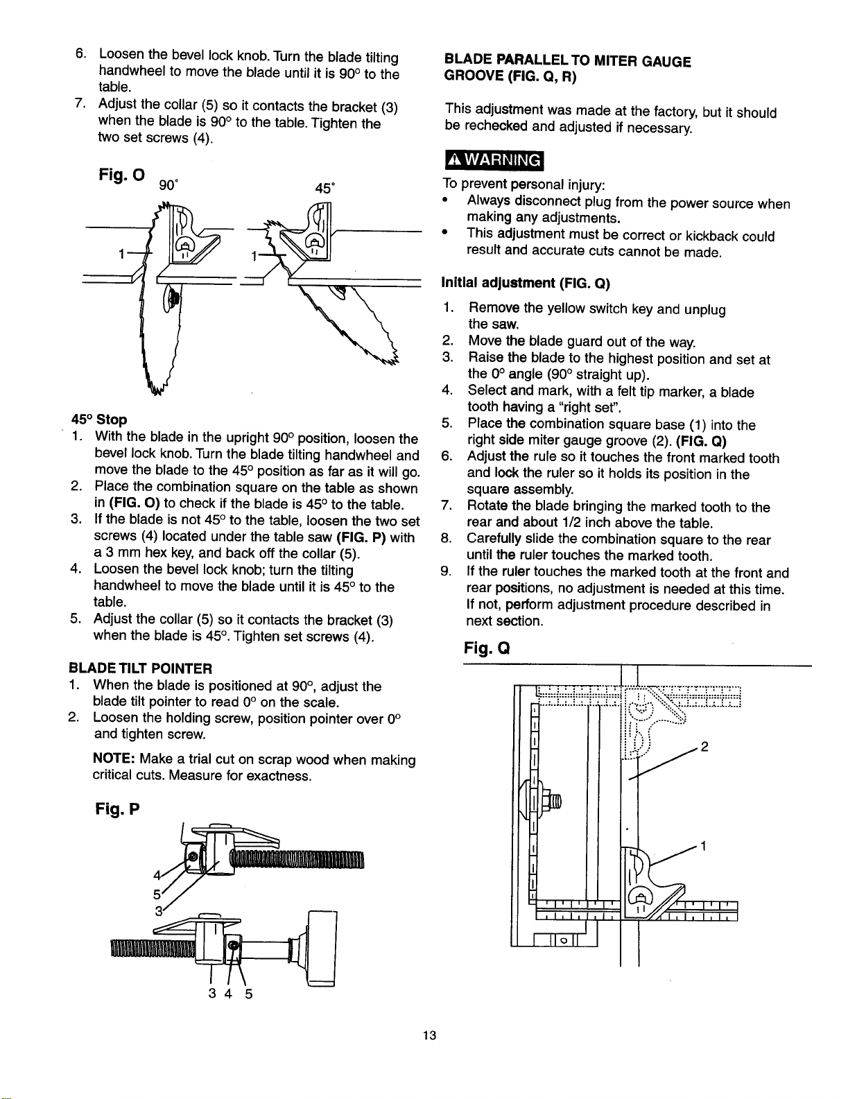
4. Place a combination square on the table and
against the blade (1) to determine if the blade
is 90° to the table. (FIG. O)
5. If the blade is not 90° to the table, loosen the two
set screws (4), located on the bottom ofthe table saw,
(FIG. P) with the hex key,and back off the collar (5).
.... 12 :
6. Loosen the bevel lock knob. Turn the blade tilting
handwheel to move the blade until it is 90° to the
table.
7. Adjust the collar (5) so it contacts the bracket (3)
when the blade is 90° to the table. Tighten the
two set screws (4).
_e
Fig. O
90° 45 °
450 Stop
1. With the blade in the upright 90° position, loosen the
bevel lock knob.Turn the blade tilting handwheel and
move the blade to the 45° position as far as itwill go.
2. Place the combination square on the table as shown
in (FIG. O) to check ifthe blade is 45° to the table.
3. If the blade is not 45° to the table, loosen the two set
screws (4) located under the table saw (FIG. P) with
a 3 mm hex key, and back offthe collar (5).
4. Loosen the bevel lock knob; turn the tilting
handwheel to move the blade until it is 45° to the
table.
5. Adjust the collar (5) so it contacts the bracket (3)
when the blade is 45°. Tighten set screws (4).
BLADE TILT POINTER
1. When the blade is positioned at 90°, adjust the
blade tilt pointer to read 0° on the scale.
2. Loosen the holding screw, position pointer over 0°
and tighten screw.
NOTE: Make a trial cut on scrap wood when making
critical cuts. Measure for exactness.
Fig. P
BLADE PARALLEL TO MITER GAUGE
GROOVE (FIG. Q, R)
This adjustment was made at the factory, but it should
be rechecked and adjusted if necessary.
To prevent personal injury:
• Always disconnect plug from the power source when
making any adjustments.
• This adjustment must be correct or kickback could
result and accurate cuts cannot be made.
Initial adjustment (FIG. Q)
1. Remove the yellow switch key and unplug
the saw.
2. Move the blade guard out of the way.
3. Raise the blade to the highest position and set at
the 0° angle (90° straight up).
4. Select and mark, with a felt tip marker, a blade
tooth having a "right set".
5. Place the combination square base (1) into the
right side miter gauge groove (2). (FIG. Q)
6. Adjust the rule so it touches the front marked tooth
and lock the ruler so it holds its position in the
square assembly.
7. Rotate the blade bringing the marked tooth to the
rear and about 1/2 inch above the table.
8. Carefully slide the combination square to the rear
until the ruler touches the marked tooth.
9. If the ruler touches the marked tooth at the front and
rear positions, no adjustment is needed at this time.
If not, perform adjustment procedure described in
next section.
Fig. O
345
13
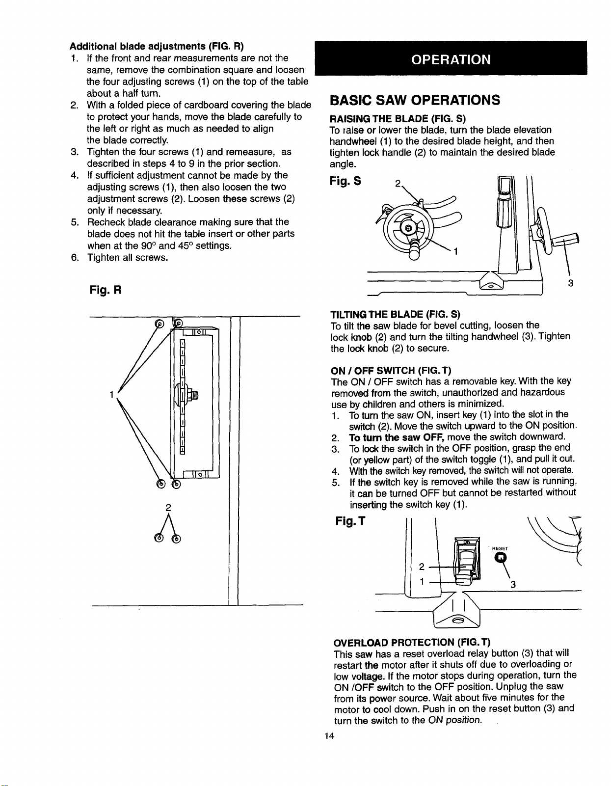
Additional blade adjustments (FIG. R)
1. Ifthe front and rear measurements are not the
same, remove the combination square and loosen
the four adjusting screws (1) on the top of the table
about a half turn.
2. With a folded piece of cardboard covering the blade
to protect your hands, move the blade carefully to
the left or right as much as needed to align
the blade correctly.
3. Tighten the four screws (1) and remeasure, as
described in steps 4 to 9 in the prior section.
4. If sufficient adjustment cannot be made by the
adjusting screws (1), then also loosen the two
adjustment screws (2). Loosen these screws (2)
only if necessary.
5. Recheck blade clearance making sure that the
blade does not hit the table insert or other parts
when at the 90° and 45° settings.
6. Tighten all screws.
Fig. R
BASIC SAW OPERATIONS
RAISING THE BLADE (FIG. S)
To raise or lower the blade, turn the blade elevation
handwheel (1) to the desired blade height, and then
tighten lock handle (2) to maintain the desired blade
angle.
Fig. S
3
2
TILTINGTHE BLADE (FIG. S)
To tilt the saw blade for bevel cutting, loosen the
lock knob (2) and turn the tiltinghandwheel (3). Tighten
the lock knob (2) to secure.
ON / OFF SWITCH (FIG. T)
The ON / OFF switch has a removable key.With the key
removed from the switch, unauthorized and hazardous
use by children and others is minimized.
1. To turn the saw ON, insert key (1) intothe slot inthe
switch (2). Move the switchupward tothe ON position.
2. To turn the saw OFF, move the switch downward.
3. To lockthe switch in the OFF position,graspthe end
(or yellow part) of the switchtoggle (1), and pullit out.
4. With theswitchkey removed,the switchwillnot operate.
5. If the switch key is removed while the saw is running,
it can be turned OFF but cannot be restarted without
inserting the switch key (1).
Fig.T
• RESET
3
OVERLOAD PROTECTION (FIG. T)
This saw has a reset overload relay button (3) that will
restart the motor after it shuts off due to overloading or
low voltage. If the motor stops during operation, turn the
ON/OFF switch to the OFF position.Unplug the saw
from its power source. Wait about five minutes for the
motor to cool down. Push in on the reset button (3) and
turn the switch to the ON position.
14
r_Lv_ d2_e
To avoid injury, the ON/OFF switch should be in the OFF
position and the plug removed from the power source
while the motor cool down takes place, to prevent
accidental starting when the reset button is pushed.
Overheating may be caused by misaligned parts or dull
blade. Inspect your saw for proper setup before using it
again.
CUTTING OPERATIONS
There are two basic types of cuts: ripping and
crosscutting. Ripping is cutting along the length and
the grain of the workpiece. Crosscutting is cutting
either across the width or across the grain of the
workpiece. Neither ripping nor crosscutting may be
done safely freehand. Ripping requires the use of the
rip fence, and crosscutting requires the miter gauge.
Before you use the saw each and every time, check
the following:
1. Blade is tight on the arbor.
2. Bevel angle lock knob is tight.
3. If ripping, fence knob is tight and fence is
parallel to the miter gauge grooves.
4. Blade guard is in place and working properly.
5. You are wearing safety glasses.
The failure to adhere to these common safety
rules, and those printed in the front of this manual,
can greatly increase the likelihood of injury.
RIPPING (FIG. U, V)
To prevent serious injury:
• Do not allow familiarity gained from the frequent use
of your table saw to cause careless mistakes.
Remember that even a careless fraction of a second
isenough to cause a severe injury.
• Keep both hands away from the blade and path of the
blade.
• The workpiece must have a straight edge against the
fence and must notbe warped, twisted,or bowed.
1. Remove the miter gauge. Secure the rip fence to
the table.
2. Raise the blade so it is about 1/8" higher than the
top of the workpiece.
3. Place the workpiece flat on the table and against the
fence. Keep the workpiece about 1" away from the blade.
4. Turn the saw ON and wait for the blade to come up
to speed.
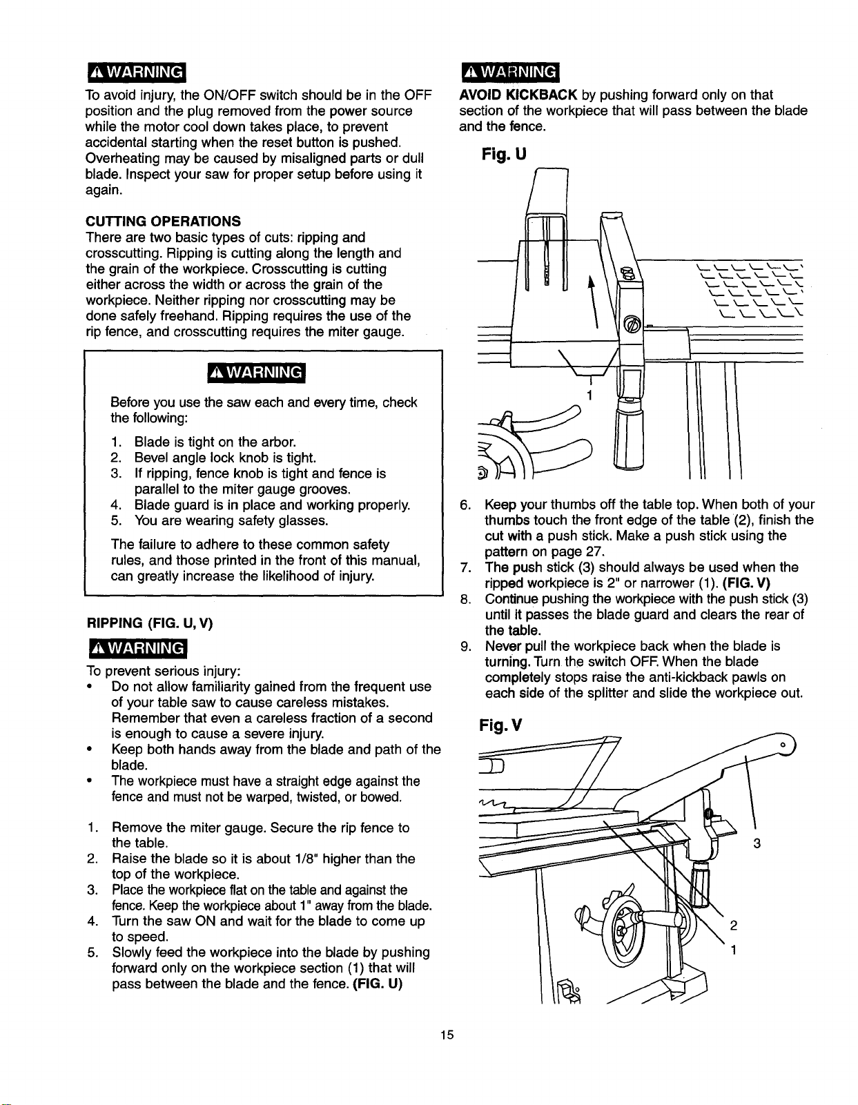
5. Slowly feed the workpiece into the blade by pushing
forward only on the workpiece section (1) that will
pass between the blade and the fence. (FIG. U)
AVOID KICKBACK by pushing forward only on that
section of the workpiece that will pass between the blade
and the fence.
Fig. U
6. Keep your thumbs off the table top. When both of your
thumbs touch the front edge of the table (2), finish the
cut with a push stick. Make a push stick using the
pattern on page 27.
7. The push stick (3) should always be used when the
ripped workpiece is 2" or narrower (1). (FIG. V)
8. Continue pushing the workpiece with the push stick (3)
until it passes the blade guard and clears the rear of
the t_le.
9. Never pull the workpiece back when the blade is
turning. Turn the switch OFF. When the blade
completely stops raise the anti-kickback pawls on
each side of the splitter and slide the workpiece out.
Fig. V
2
1
15

BEVEL RIPPING
This cut is the same as ripping except the blade bevel
angle is set to an angle other than 0°.
Cut only with the workpiece and the fence on the right
side of the blade.
RIPPING SMALL PIECES
rv_kvAvl__1_|_II_€
Avoid injury from blade contact. Never make through-saw
cuts narrower than 1/2" wide.
,
2.
It is unsafe to rip small pieces. Instead, rip a larger
piece to obtain the size of the desired piece.
When a small width is to be ripped and your hand
cannot be safely put between the blade and the
rip fence, use one or more push sticks to move
the workpiece.
CROSSCUTTING (FIG. W)
To prevent serious injury:
• Do not allow familiarity gained from the frequent use
of your table saw to cause careless mistakes.
Remember that even a careless fraction of a second
isenough to cause a severe injury.
• Keep both hands away from the blade and path of the
blade.
1. Remove the rip fence and place the miter gauge in
the left side groove.
2. Adjust the blade height so it is 1/8" higher than the
top of the workpiece.
3. Hold the workpiece firmly against the miter gauge
with the blade path in line with the desired cut
location. Move the workpiece to one inch distance
from the blade.
4. Start the saw and wait for the blade (1) to come up to
full speed.
5. Keep the workpiece (2) against the face of the miter
gauge (3) and flat against the face of the gauge and
flat against the table. Then slowly push the
workpiece through the blade (FIG. W).
6. Do not try to pull the workpiece back with the blade
turning. Turn the switch OFF, and carefully slide the
workpiece out when the blade is completely stopped.
Fig. W
3 2
BEVEL CROSSCUTTING (FIG. X)
This cutting operation is the same as crosscutting except
the blade is at bevel angle other than 0°.
1. Adjust the blade (1) to the desired angle, and tighten
the blade bevel lock knob.
2. Always work to the left side of the blade. The miter
gauge (3) must be in the leftside groove (2). It
cannot be used in the right side groove unless the
miter angle is very sharp, as it will interfere with the
blade guard.
Fig. X
2
1
\Of
n
16
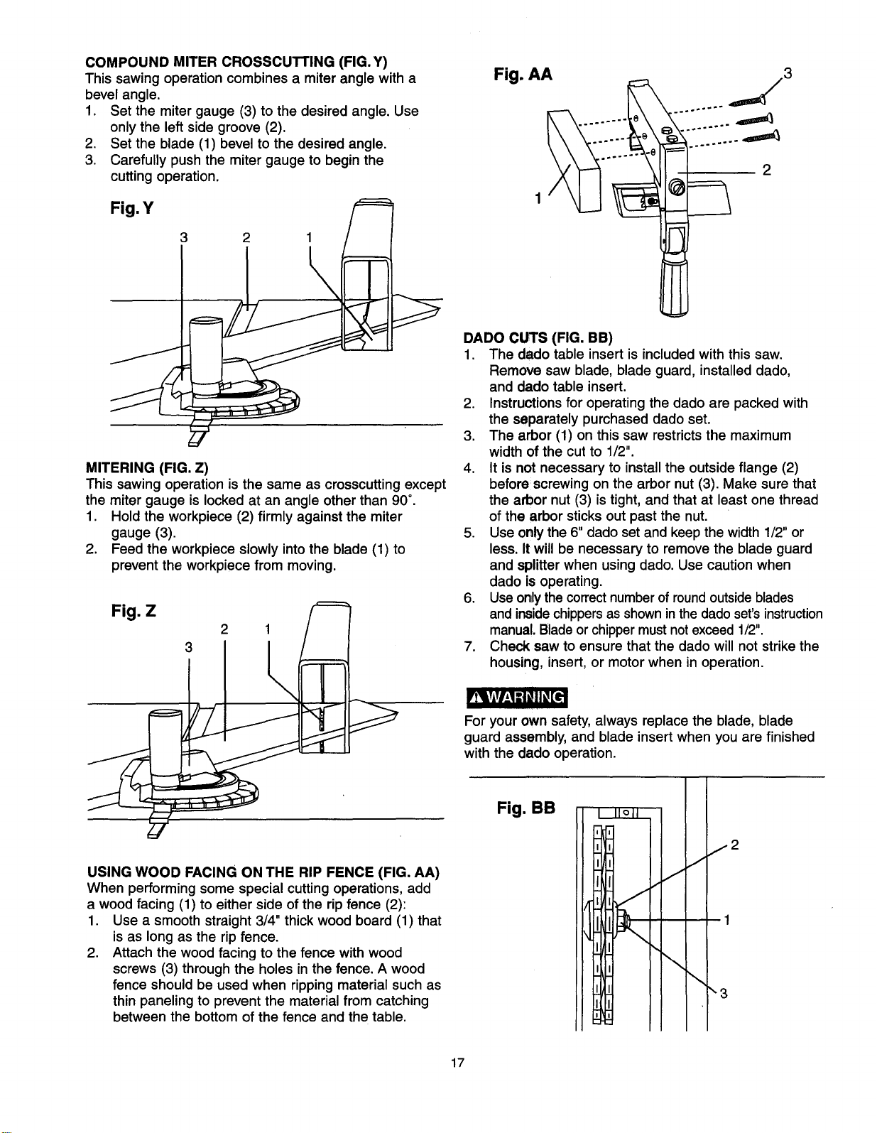
COMPOUND MITER CROSSCUTTING (FIG.Y)
This sawing operation combines a miter angle with a
bevel angle.
1. Set the miter gauge (3) to the desired angle. Use
only the left side groove (2).
2. Set the blade (1) bevel to the desired angle.
3. Carefully push the miter gauge to begin the
cutting operation.
Fig.Y /_
Fig. AA
1
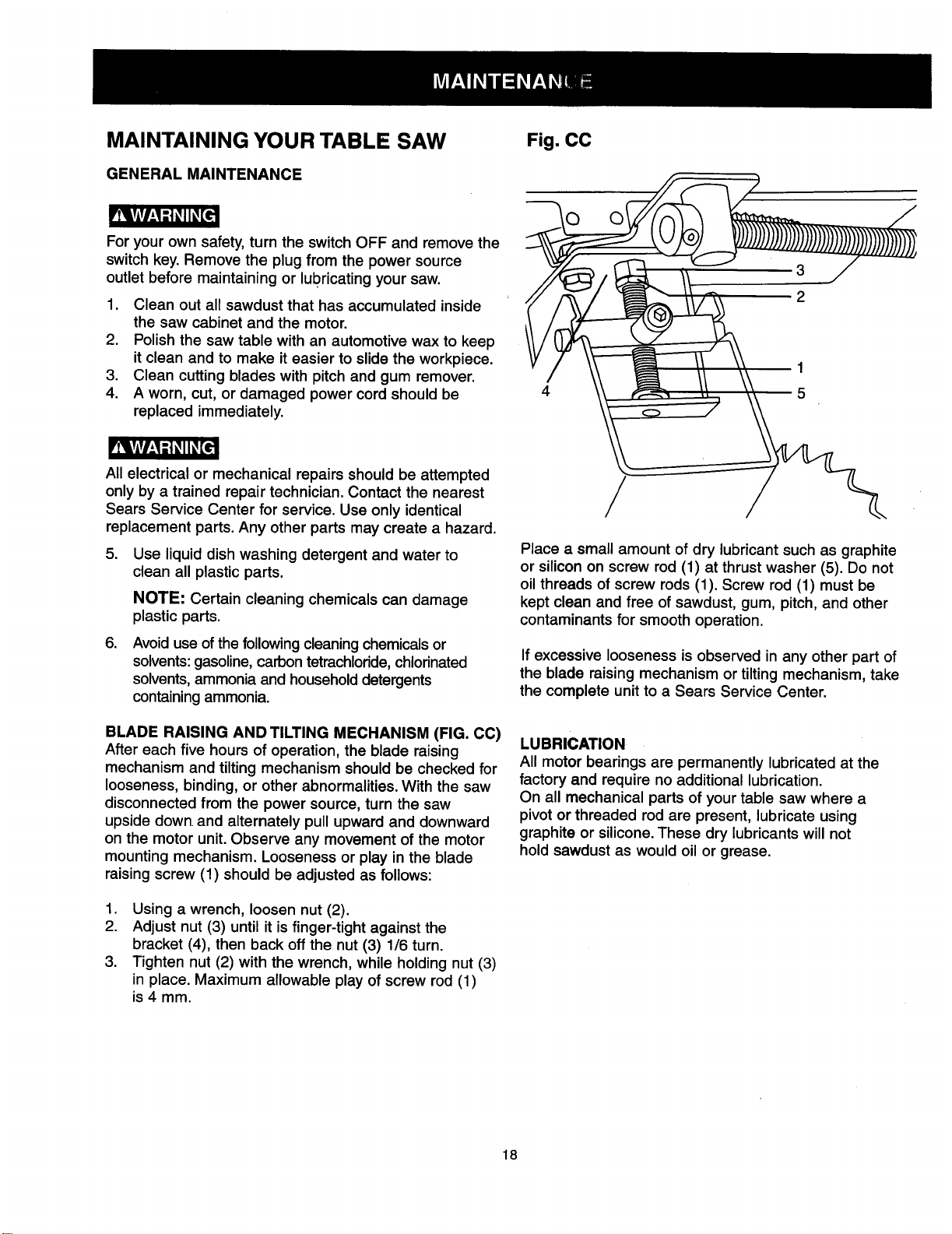
DADO CUTS (FIG. BB)
1.
2.
3.
MITERING (FIG. Z)
This sawing operation is the same as crosscutting except
the miter gauge is locked at an angle other than 90°,
1. Hold the workpiece (2) firmly against the miter
gauge (3),
2. Feed the workpiece slowly intothe blade (1) to
prevent the workpiece from moving.
Fig.
Z
2 1 / I
5r
rt_kv_v_l_[e
USING WOOD FACING ON THE RIP FENCE (FIG. AA)
When performing some special cutting operations, add
a wood facing (1) to either side of the rip fence (2):
1. Use a smooth straight 3/4" thick wood board (1) that
is as long as the rip fence.
2. Attach the wood facing to the fence with wood
screws (3) through the holes in the fence. A wood
fence should be used when rippingmaterial such as
thin paneling to prevent the material from catching
between the bottom of the fence and the table.
... _3
F
2
The dado table insert is included with this saw.
Remove saw blade, blade guard, installed dado,
and dado table insert.
Instructions for operating the dado are packed with
the separately purchased dado set.
The arbor (1) on this saw restricts the maximum
width of the cut to 1/2".
4. It is not necessary to install the outside flange (2)
before screwing on the arbor nut (3). Make sure that
the arbor nut (3) is tight, and that at least one thread
of the arbor sticks out past the nut.
5. Use only the 6" dado set and keep the width 1/2" or
less. It will be necessary to remove the blade guard
and splitter when using dado. Use caution when
dado is operating.
6. Useonly the correct number of round outside blades
and inside chippers as shown in the dado set's instruction
manual. Blade or chipper must not exceed 1/2".
7. Check saw to ensure that the dado will not strike the
housing, insert, or motor when in operation.
For your own safety, always replace the blade, blade
guard assembly, and blade insert when you are finished
with the dado operation.
Fig. BB
I
17
MAINTAINING YOUR TABLE SAW
GENERAL MAINTENANCE
For your own safety, turn the switch OFF and remove the
switch key. Remove the plug from the power source
outlet before maintaining or lubricating your saw.
1. Clean out all sawdust that has accumulated inside
the saw cabinet and the motor.
2. Polish the saw table with an automotive wax to keep
it clean and to make it easier to slide the workpiece.
3. Clean cutting blades with pitch and gum remover.
4. A worn, cut, or damaged power cord should be
replaced immediately.
All electrical or mechanical repairs should be attempted
only by a trained repair technician. Contact the nearest
Sears Service Center for service. Use only identical
replacement parts. Any other parts may create a hazard.
5. Use liquid dish washing detergent and water to
clean all plastic parts.
NOTE: Certain cleaning chemicals can damage
plastic parts.
.
Avoid use of the following cleaningchemicalsor
solvents: gasoline, carbon tetrachloride,chlorinated
solvents, ammonia and household detergents
containing ammonia.
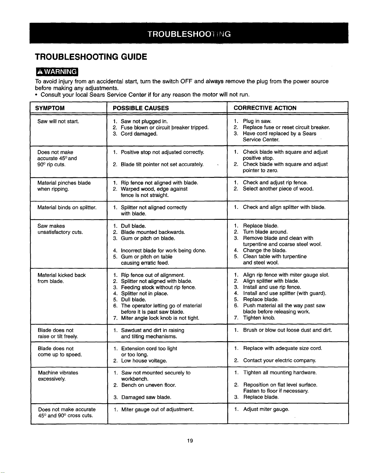
BLADE RAISING AND TILTING MECHANISM (FIG. CC)
After each five hours of operation, the blade raising
mechanism and tilting mechanism should be checked for
looseness, binding, or other abnormalities. With the saw
disconnected from the power source, turn the saw
upside down.and alternately pull upward and downward
on the motor unit. Observe any movement of the motor
mounting mechanism. Looseness or play in the blade
raising screw (1) should be adjusted as follows:
1. Using a wrench, loosen nut (2).
2. Adjust nut (3) until it is finger-tight against the
bracket (4), then back off the nut (3) 1/6 turn.
3. Tighten nut (2) with the wrench, while holding nut (3)
in place. Maximum allowable play of screw rod (1)
is 4 mm.
Fig. CC
/
Place a small amount of dry lubricant such as graphite
or silicon on screw rod (1) at thrust washer (5). Do not
oil threads of screw rods (1). Screw rod (1) must be
kept clean and free of sawdust, gum, pitch, and other
contaminants for smooth operation.
If excessive looseness is observed in any other part of
the blade raising mechanism or tilting mechanism, take
the complete unit to a Sears Service Center.
LUBRICATION
All motor bearings are permanently lubricated at the
factory and require no additional lubrication.
On all mechanical parts of your table saw where a
pivot or threaded rod are present, lubricate using
graphite or silicone. These dry lubricants will not
hold sawdust as would oil or grease.
18
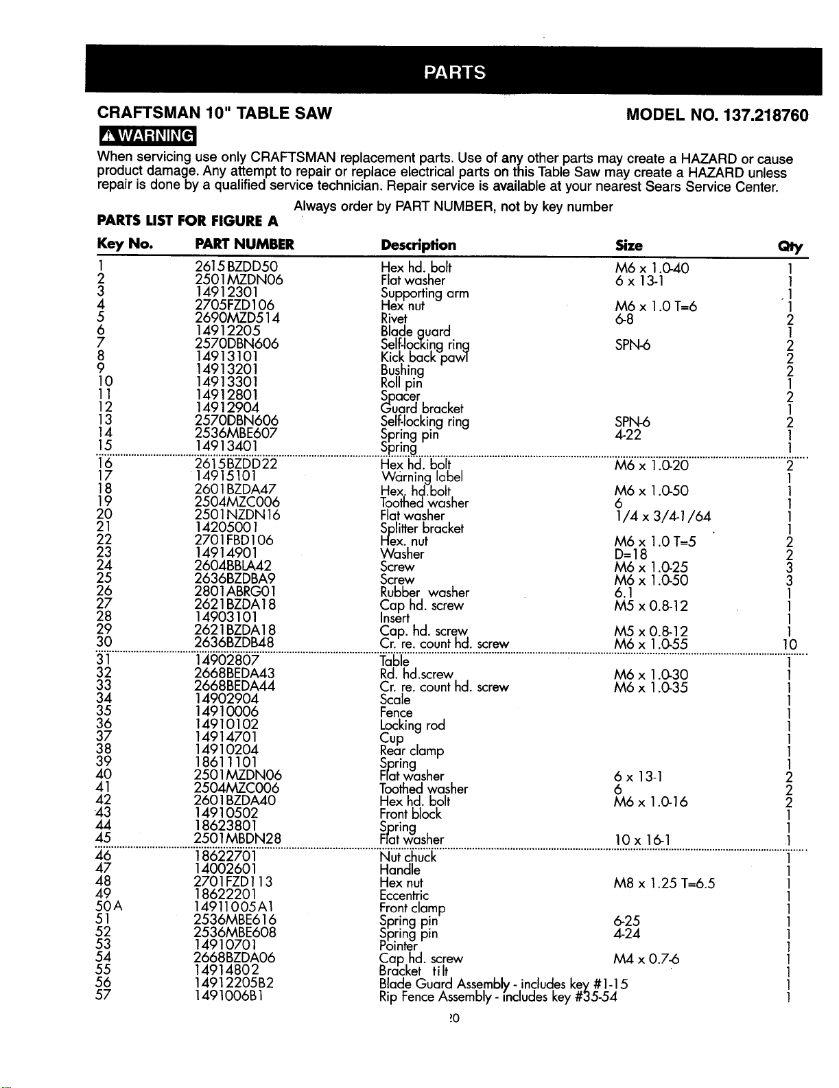
TROUBLESHOOTING GUIDE
To avoid injury from an accidental start, turn the switch OFF and always remove the plug from the power source
before making any adjustments.
= Consult your local Sears Service Center if for any reason the motor will not run.
SYMPTOM POSSIBLE CAUSES CORRECTIVE ACTION
Saw will not start. 1. Saw not plugged in. 1. Plug in saw.
2. Fuse blown or circuit breaker tripped. 2. Replace fuse or reset circuit breaker.
3. Cord damaged. 3. Have cord replaced by a Sears
Service Center.
Does not make 1. Positive stop not adjusted correctly. 1. Check blade with square and adjust
accurate 45°and positive stop.
90° rip cuts. 2. Blade tilt pointer not set accurately. 2. Check blade with square and adjust
pointer to zero.
Material pinches blade 1. Rip fence not aligned with blade. 1. Check and adjust rip fence.
when ripping. 2. Warped wood, edge against 2. Select another piece of wood.
fence is not straight.
Material binds on splitter. 1. Splitter not aligned correctly 1. Check and align splitter with blade.
with blade.
Saw makes
unsatisfactory cuts.
Material kicked back
from blade.
Blade does not
raise or tilt freely.
Blade does not
come up to speed.
Machine vibrates
excessively.
Does not make accurate
45° and 90° cross cuts.
1. Dull blade.
2. Blade mounted backwards.
3. Gum or pitch on blade,
4. Incorrect blade for work being done.
5. Gum or pitch on table
causing erratic feed.
1. Rip fence out of alignment.
2. Splitter not aligned with blade.
3, Feeding stock without rip fence.
4. Splitter not in place.
5. Dull blade.
6. The operator letting go of material
before it is past saw blade.
7. Miter angle lock knob is not tight.
1. Sawdust and dirt in raising
and tilting mechanisms.
1. Extension cord too light
or too long.
2. Low house voltage,
1. Saw not mounted securely to
workbench.
2. Bench on uneven floor.
3. Damaged saw blade.
1. Miter gauge out of adjustment.
1. Replace blade.
2. Turn blade around.
3. Remove blade and clean with
turpentine and coarse steel wool.
4. Change the blade.
5. Clean table with turpentine
and steel wool.
1. Align rip fence with miter gauge slot.
2. Align splitter with blade.
3. Install and use rip fence.
4. Install and use splitter (with guard).
5. Replace blade.
6. Push material all the way past saw
blade before releasing work.
7. Tighten knob.
1. Brush or blow out loose dust and dirt.
1. Replace with adequate size cord.
2. Contact your electric company.
1. Tighten all mounting hardware.
2. Reposition on flat level surface.
Fasten to floor if necessary,
3. Replace blade.
1. Adjust miter gauge.
19
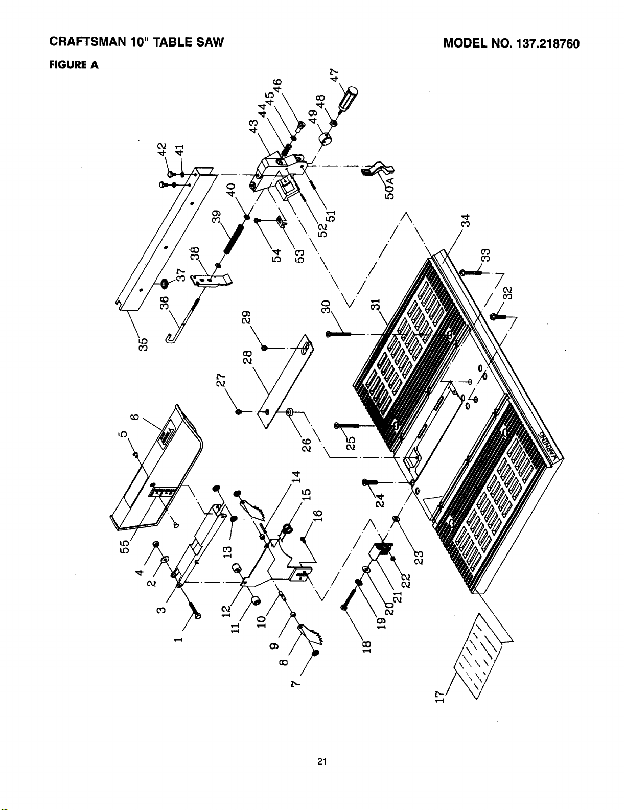
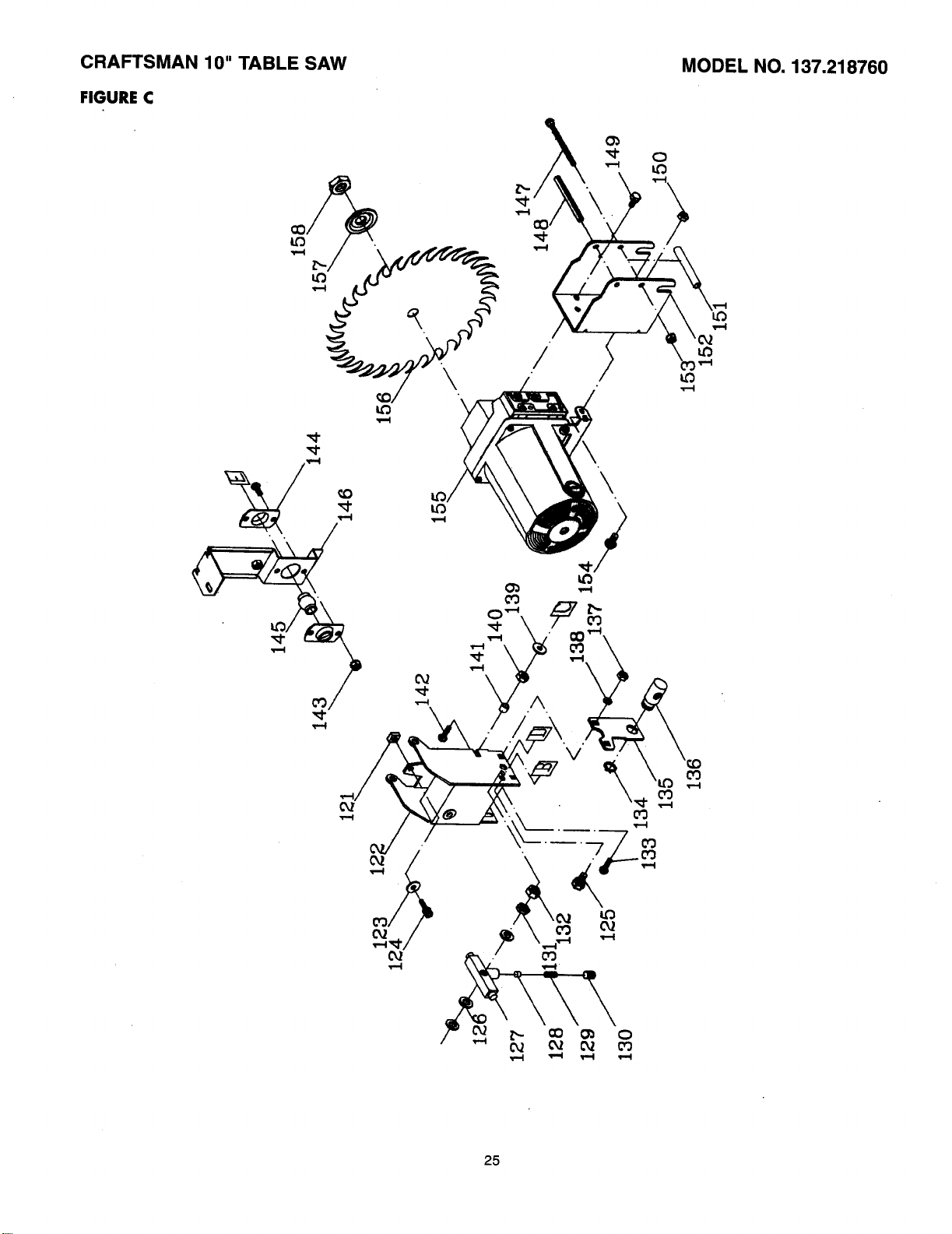
CRAFTSMAN 10" TABLE SAW MODEL NO. 137.218760
_€
When servicing use only CRAFTSMAN replacement parts. Use of any other parts may create a HAZARD or cause
product damage. Any attempt to repair or replace electrical parts on this Table Saw may create a HAZARD unless
repair is done by a qualified service technician. Repair service is available at your nearest Sears Service Center.
Always order by PART NUMBER, not by key number
PARTS LIST FOR FIGURE A
Key No. PART NUMBER Description Size Qty
1 2615 BZDD50 Hex hd. bolt M6 x 1.0-40 1
2 2501MZDN06 Flat washer 6 x 13-1 1
3 14912301 Supporting arm ,1
4 2705FZD106 Hex nut M6 x 1.0 T=6 1
5 2690MZD514 Rivet 6-8 2
6 14912205 Blade .auard 1
7 2570DBN606 Sel[-Ioc'_ingrin_! SPN-6 2
8 14913101 _JcKDaCKpawl 2
9 14913201 Bushing 2
10 14913301 Roll pin 1
11 14912801 GuadSDaCrer 2
12 14912904 bracket 1
13 2570DBN606 Self-locking ring SPN-6 2
14 2536MBE607 Spring pin 4-22 1
15 14913401 Spring 1
.............................. ......................................Fl'ex" l':"l off.....................................................................................................
17 14915101 Wcirning label 1
18 2601BZDA47 Hex. hd.bolt M6 x 1.0-50 1
19 2504MZC006 Toothed washer 6 1
20 2501NZDN 16 Flat washer 1/4 x 3/4-1/64 1
21 1420500 ] .Splitterbracket 1
22 2701FBD106 Hex. nut M6 x 1.0 T--5 2
23 14914901 Washer D=18 2
24 2604BBLA42 Screw M6 x 1.0-25 3
25 2636BZDBA9 Screw M6 x 1.0-50 3
26 2801ABRGO 1 Rubber washer 6.1 1
27 2621BZDA18 .Cap hd. screw M5 x 0.8-12 1
28 14903101 Insert 1
29 2621BZDA18 Cap. hd. screw M5 x 0.8-12 1
30 2636BZDB48 Cr. re. count hd. screw M6 x 1.0-55 10
................................ ............................................?a'l Ye..........................................................................................................................................i......
32 2668BEDA43 Rd. hd.screw M6 x 1.0-30 1
33 2668BEDA44 Cr. re. count hd. screw M6 x 1.0-35 1
34 14902904 Scale 1
35 14910006 Fence 1
36 14910102 Locking rod 1
37 14914701 Cup 1
38 14910204 Rear clamp 1
39 18611101 Spring 1
40 2501MZDN06 Flat washer 6 x 13-1 2
41 2504MZC006 Toothed washer 6 2
42 2601BZDA40 Hex hd. bolt M6 x 1.0-16 2
:43 14910502 Front block 1
44 18623801 Spring 1
45 2501MBDN28 Fratwasher 10 x 16-1 .1
............................................................................ uicl uc ................................................................................................................................i......
47 14002601 Handle 1
48 2701FZD113 Hex nut M8 x 1.25 T=6.5 1
49 18622201 Eccentric 1
50A 14911005A1 Front clamp 1
51 2536MBE616 Spring pin 6-25 1
52 2536MBE608 Spring pin 4-24 1
53 14910701 Pointer 1
54 2668BZDA06 Cap,hd. screw M4 x 0.7-6 1
55 14914802 mracket tilt 1
56 14912205 B2 Blade Guard Assembly- includes key # 1-15 1
57 1491006B 1 Rip Fence Assembly -{ncludes key #35-54 1
_0
CRAFTSMAN 10" TABLE SAW
FIGURE A
A
/ \
/ \
!
\ /
MODEL NO. 137.218760
cO
\
21
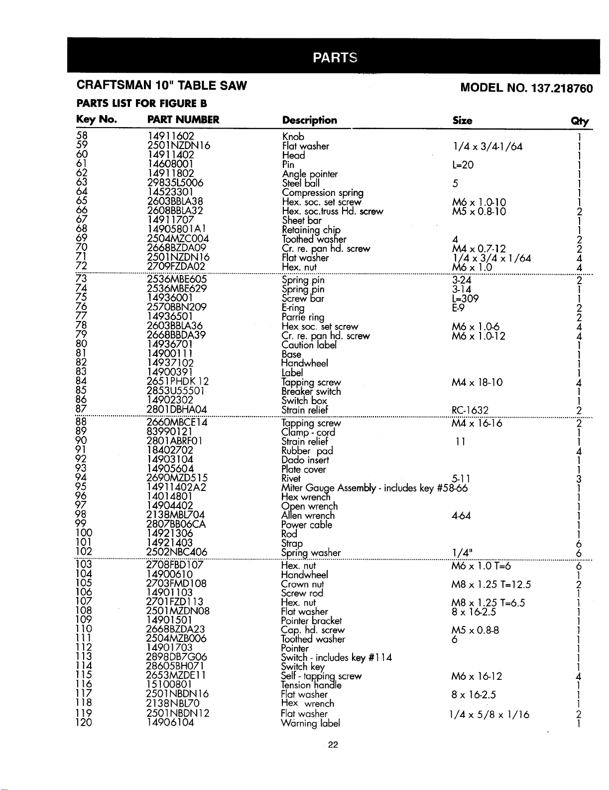
CRAFTSMAN 10" TABLE SAW
PARTS LIST FOR FIGURE B
MODEL NO. 137.218760
Key No. PART NUMBER Description Size Qty
58 14911602 Knob 1
59 2501NZDN 16 Flatwasher 1/4 x 3/4-1/64 1
60 14911402 Head 1
61 14608001 Pin L--20 1
62 14911802 Ang!e pointer 1
63 29835L5006 _teel ball 5 1
64 14523301 Compression spring 1
65 2603BBLA38 Hex. soc. set screw M6 x 1.0-10 1
66 2608BBLA32 Hex. soc.truss Hd. screw M5 x 0.8-10 2
67 14911707 Sheetbar 1
68 14905801A 1 Retaining chip 1
69 2504MZC004 Toothed wasBer 4 2
70 2668BZDA09 Cr. re. pan hd. screw M4 x 0.7-12 2
71 2501NZDN16 Flat washer 1/4 x 3/4 x 1/64 4
72 2709FZDA02 Hex. nut M6 x 1.0 4
.............................. ................................................................................................................................................................
74 2536MBE629 Spring pin 3-14 1
75 14936001 Screw Bar L=309 1
76 2570BBN209 E-ring E-9 2
77 14936501 Parrie ring 2
78 2603BBLA36 Hex soc. set screw M6 x 1.0-6 4
79 2668BBDA39 Cr. re. pan hd. screw M6 x 1.0-12 4
80 14936701 Caution label 1
81 14900111 Base 1
82 14937102 Handwheel 1
83 14900391 Label 1
84 2651PHD K 12 Tapp,ing screw M4 x 18,-10 4
85 2853U55501 Breaker switch 1
86 14902302 Switch box 1
87 2801 DBHA04 Strain relief RC-1632 2
...................................................................?a' 'p]'n "screw..................................................................................................
89 83990121 Clamp- cord 1
90 2801ABRF01 Strain relief 11 1
91 18402702 Rubber pad 4
92 14903104 Dado insert 1
93 14905604 Platecover 1
94 2690MZD515 Rivet 5-11 3
95 14911402A2 Miter Gauge Assembly- includes key #58-66 1
96 14014801 Hex wrench 1
97 14904402 Open wrench 1
98 2138MBL704 Allen wrench 4-64 1
99 2807BB06CA Power cable 1
100 14921306 Rod 1
101 14921403 Strap 6
!02 2502NBC406 ............... Spring washer . 1/4" 6
103 2708FBD107 Pl'ex'_"nul: " M6"'x"i i0":1:'"6.................................6.....
104 14900610 Handwheel 1
105 2703FMD108 Crown nut M8 x 1.25 T=I 2.5 2
106 14901103 Screw rod 1
107 2701FZD113 Hex. nut M8 x 1.25 T=6.5 1
108 2501MZDN08 Flat washer 8 x 16-2.5 1
109 14901501 Pointer bracket 1
110 2668BZDA23 Cap.. hd. screw M5 x 0.8-8 1
111 2504MZB006 Toothed washer 6 1
112 14901703 Pointer 1
113 2898DB7G06 Switch- includes key #114 1
114 28605BH071 Switch key 1
115 2653MZDE 11 Self- tap.ping,screw M6 x 16-12 4
116 15100801 lension handle 1
117 2501NBDN 16 Flat washer 8 x 16-2.5 1
118 2138NBL70 Hex wrench 1
119 2501NBDN12 Flat washer 1/4 x 5/8 x 1/16 2
120 14906104 Wc_rning label 1
22
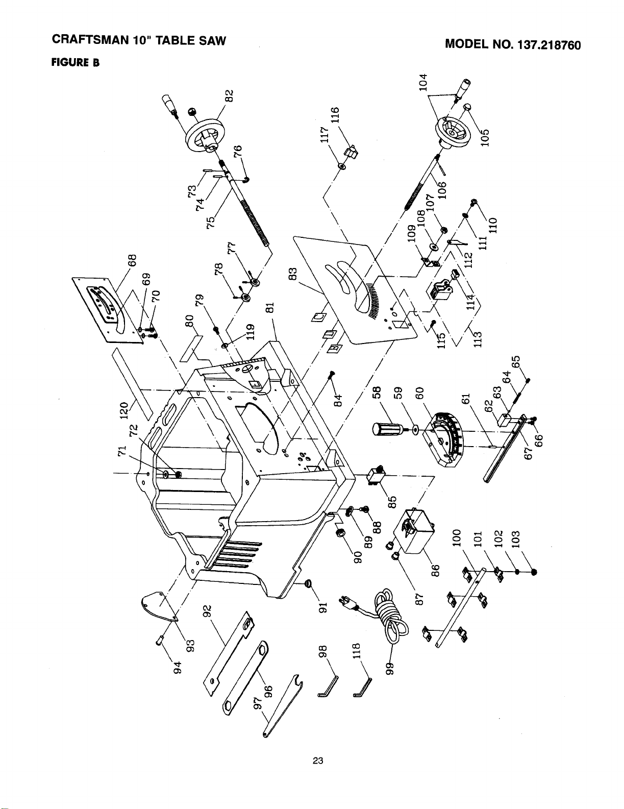
CRAFTSMAN 10" TABLE SAW MODEL NO. 137.218760
FIGURE B
C33
\
7
/
/
23
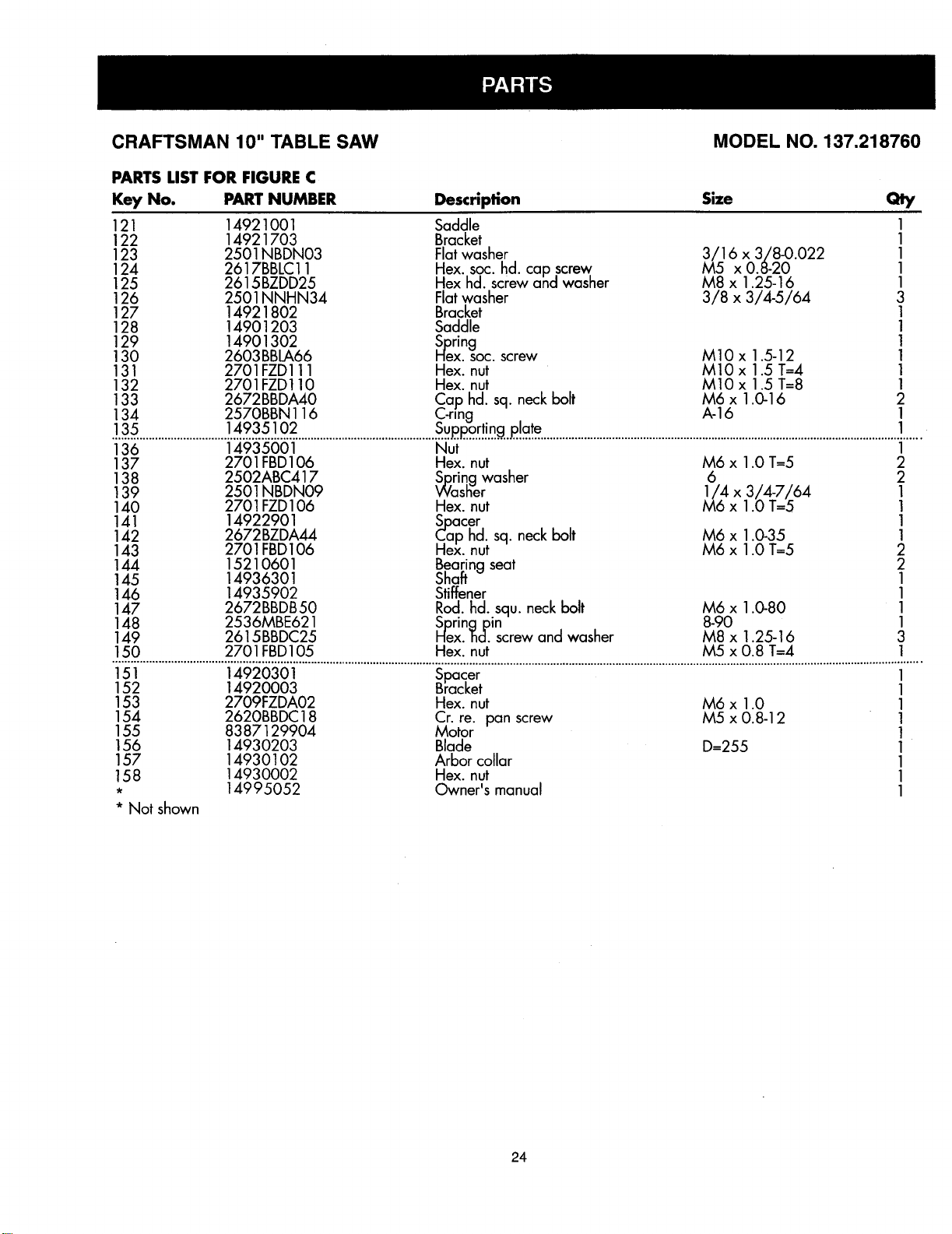
CRAFTSMAN 10" TABLE SAW MODEL NO. 137.218760
PARTS LIST FOR FIGURE C
Key No. PART NUMBER Description Size Qty
121 14921001 Saddle 1
122 14921703 Bracket 1
123 2501NBDN03 Flat washer 3/16 x 3/8-0.022 1
124 2617BBLC11 Hex. soc. hd. cap screw M5 x 0.8-20 1
125 2615BZDD25 Hex hd. screw and washer M8 x 1.25-16 1
126 2501 NNHN34 Flat washer 3/8 x 3/4-5/64 3
127 14921802 Bracket 1
128 14901203 Saddle 1
129 14901302 Spring 1
130 2603BBLA66 nex. soc. screw M10 x 1.5-12 1
131 2701FZD111 Hex. nut M10 x 1.5 T--4 1
132 2701FZD110 Hex. nut MIO x 1.5 T=8 1
133 2672BBDA40 Cap hd. sq. neck bolt M6 x 1.0-16 2
134 2570BBN 116 C-ring A-16 1
.!..3.5.............................].49..s..s...!.02.....................................................................................................................................................................
136 14935001 Nut 1
137 2701FBD106 Hex. nut M6 x 1.0 T=5 2
138 2502ABC417 Spring washer 6 2
139 2501NBDN09 Washer 1/4 x 3/4-7/64 1
140 2701FZD106 Hex. nut M6 x 1.0 T=5 1
141 14922901 Spacer 1
142 2672BZDA44 Cap hd. sq. neck bolt M6 x 1.0-35 1
143 2701FBD106 Hex. nut M6 x 1.0 T=5 2
144 15210601 Bearing seat 2
145 14936301 Shatt 1
146 14935902 Stiffener 1
147 2672BBDB50 Rod. hd. squ. neck bolt M6 x 1.0-80 1
148 2536MBE621 SDrinc_Din 8-90 1
149 2615BBDC25 Hex. 'Bcl.screw and washer M8 x 1.25-16 3
150 2701FBD105 Hex. nut M5 x 0.8 T=4 1
151 14920301 Spacer 1
152 14920003 Bracket 1
153 2709FZDA02 Hex. nut
154 2620BBDC18 Cr. re. pan screw
155 8387129904 Motor
156 14930203 Blade
157 14930102 Arbor collar
158 14930002 Hex. nut
• 14995052 Owner's manual
• Not shown
M6 x 1.0
M5 x 0.8-12
D--255
1
1
1
1
1
1
1
24
CRAFTSMAN 10" TABLE SAW
FIGURE C
MODEL NO. 137.218760
\
\
25

26
/
/
/
/
/
/
/
/
/
:_-_
Z Q.
ffJ
............... 27

28
I
l
,
I
I
I
I
I
J J
J j
J
I/I
/
/
/
-j
_!0Io
/ J
I
!
I
/
/
/
/
/
___o
_o
I
I
f
/
!-
C
J
J
/
o/
w
,-o._
.0 0 C:D
C_."_ "_
'0_ "--
o
I
I
oo
0 =
o
29

30
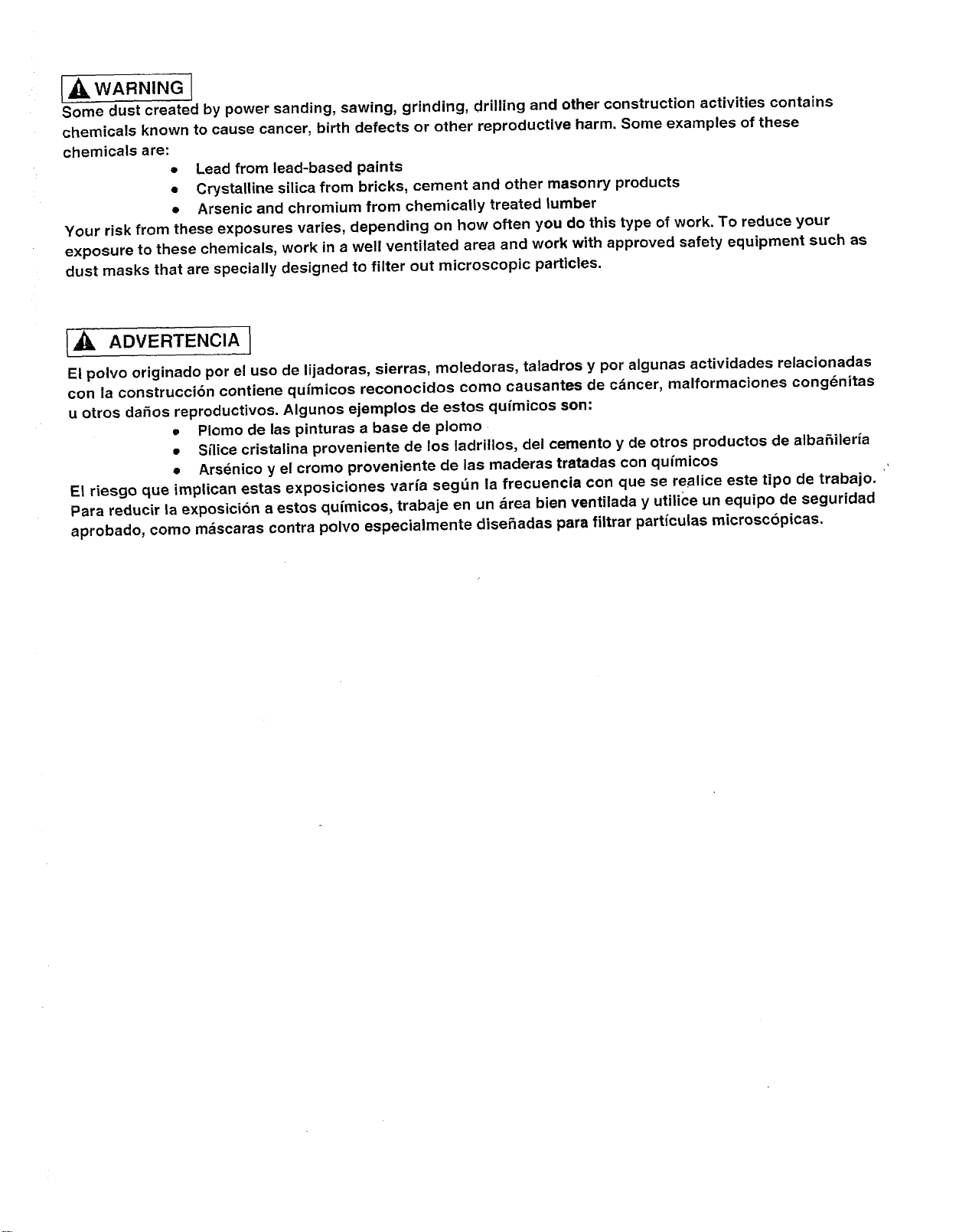
[_1_ WARNING (
Some dust created by power sanding, sawing, grinding, drilling and other construction activities contains
chemicals known to cause cancer, birth defects or other reproductive harm. Some examples of these
chemicals are:
o Lead from lead-based paints
• Crystalline silica from bricks, cement and other masonry products
• Arsenic and chromium from chemically treated lumber
Your risk from these exposures varies, depending on how often you do this type of work. To reduce your
exposure to these chemicals, work in a well ventilated area and work with approved safety equipment such as
dust masks that are specially designed to filter out microscopic particles.
ADVERTENCIA I
El polvo originado por el uso de lijadoras, sierras, moledoras, taladros y pot algunas actividades relacJonadas
con la construcci6n contiene qufmicos reconocidos como causantes de c_ncer, malformaciones cong_nitas
u otros da_os reproductivos, Algunos ejempios de estos qufmicos son:
• Plomo de las pinturas a base de plomo
• Silice cristalina proveniente de los ladritlos, del cemento y de otros productos de alba_ileria
• Ars_nico y el cromo proveniente de las maderas tratadas con quimicos
El riesgo que implican estas exposiciones varfa seg_n la frecuencia con que se realice este tipo de trabajo.
Para reducir la exposici6n a estos quimicos, trabaje en un &tea bien ventilada y utilice un equipo de seguridad
aprobado, como m_scaras contra polvo especialmente dise_adas para filtrar particulas microscbpicas.

For in-home major brand repair service:
Call 24 hours a day, 7 days a week
1-800-4-MY-HOME" (1-800-469-4663)
Para pedir servicio de reparaci6n a domicilio - 1-800-676-5811
In Canada for all your service and parts needs call
- 1-800-665-4455
Au Canada pour tout le service ou les pi_ces
For the repair or replacement parts you need:
Call 6 a.rn. - 11 p.m. CST, 7 days a week
PartsDirect TM
1-800-366-PART (1-800-366-7278)
Para ordenar piezas con entrega a domicilio - 1-800-659-7084
For the location of a Sears Service Center in your area:
Call 24 hours a day, 7 days a week
1-800-488-1222
To purchase or inquire about a Sears Maintenance Agreement:
Call 7 a.m. - 5 p.m. CST, Monday - Saturday
1-800-827-6655
F •
SEARS
HomeCentral °"
8/99
Manual de Operacibn
CRRFTSMRN"
2.5 HP (Potencia Mdxima)
Hoja Circular de 25.4cm (10")
5000 R.P.M.
SIERRA DE MESA
Modelo No.
137.218760
10.in.
TABLE
SAW _
F
CUIDADO:
Antes de usar esta Sierra de Mesa,
leer este manual y seguir todas sus
Reglas de Seguridad e Instrucciones
de OperaciSn.
• Instrucciones de Seguridad
• InstalaciSn
• OperaciSn
• Mantenimiento
• Lista de Partes
Tel6fono para
Ayuda al Cliente
1-800-843-1682
Sears, Roebuck and Co., Hoffman Estates, IL 60179 USA
Part No. 137218760001
SECCION PAGINA
Garantia ................................................................. 32
Especificaciones de la Herramienta .......................................... 32
Instrucciones de Seguridad ................................................. 33
Accesorios y Aditamentos .................................................. 36
Herramientas necesarias para el ensamblaje ................................... 36
Contenido de la Caja ....................................................... 36
Familiarizarse con la Sierra de Mesa .......................................... 38
Ensamblaje y Regulacibn ................................................... 39
Operacibn ............................................................... 44
Mantenimiento ........................................................... 48
Guia para Diagndstico de Problemas ......................................... 49
Partes .................................................................. 50
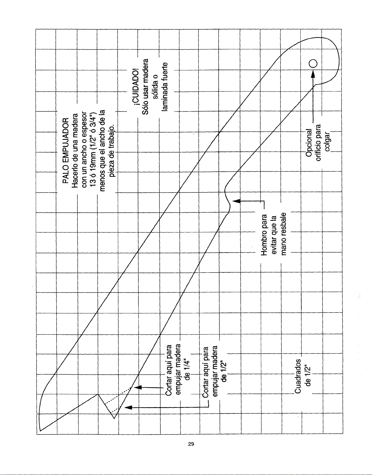
Para hacer un palo empujador .. ............................................ 29
GARANT|ATOTALDE 1 ANO
Siesta herramientapresentasedefectosdematerial o fabricaci6ndentrodel primerafio a partirde la fechade compra,
Sears la repararasincostoalguno.
ContactarseconunCentr0 de Serviciode Searsparala reparaci6n.
Si estaherramientase usaparafines comercialesoparaalquiler,estagarantfaseaplicas61oporlosprimeros90 a partir
de lafechade compra.
Estagarantiate otorgaderechos legalesespecfficosy tambi_n podria usted tenerotros derechosque varian de un
estado a otro.
Sears, Roebuck and Co., Dept. 817 WA, Hoffman Estates, IL 60179
MOTOR
Caballajemaximoquedesarrolla....... 2.5 HP
Voltios ............................ 120
Amperios.......................... 13
Hertzios........................... 60
RPM (Sincarga) ................... 5000
Protecci6ndesobrecarga ............ SI
SIERRA
Mesa ............................ 17-1/8"x26"
(43.5cm x 66 cm
Hoja ............................. 10"(25.4cm)
Profundidadm_ima de corte a 90° ..... 3" (7.6cm)
Profundidadm_ima de corte a 45o ..... 2-1/2" (6.3cm)
Ancho m_.ximopara ranurar ........... 1/2"(1.27cm)
Peso ........................... 40 Lbs(18 Kg.)
Paraevitar riesgosel_ctricos,de incendioo de dafios a la
herramienta,usarun protectorapropiadode circuito.
La sierrade mesa vienecableadade f_.bricapara operarcon
120V. Enchufarlaa un circuitode 120V,15 Amp.que tengaun
fusible de retardoo un interruptorde circuitode 15Amp. Para
evitarchoquesel_ctricoso incendios,reempiazarel cord6n
electricoinmediatamentesi estuviesegastado,cortado o
dafiadoen cualquierforma.
32
INSTRUCCIONES GENERALES DE
SEGURIDAD
ANTES DE USAR LA SIERRA DE MESA
Laseguridades una combinaci6nde sentidocom_n,mantenerse
alertay conocercomofuncionala sierrade mesa.
Paraevitarerroresquepuedancausar lesionesserias,no
conectarla Sierrahasta haberlefdoy entendidoIosiguiente:
,
.
,
,
LEERy familiarizarsecon todoeste manualde instrucciones.
ENTENDERlasaplicaciones,limitacionesy riesgosposibles.
MANTENERLOS PROTECTORESENPOSICIONy en
buenascondicionesde operaci6n.
RETIRARL.ASHERRAMIENTASY LLAVESDE
REGULACIONY AJUSTE.Formarseel h_.bitode verificar
quelasherramientasy lasIlavesderegulaci6nhayanside
retiradasde laherramientaantesdeactivarla.
MANTENERELAREA DETRABAJOLIMPIA.Las_reas
y mesasdetrabajocongestionadasinvitana que ocurran
accidentes.
5. NOOPERAR ENAMBIENTESPELIGROSOS.No usarla
herramientaenlugaresht_medos,mojadosoexpuestosa la
Iluvia.Mantenerel_rea detrabajobieniluminada.
6. MANTENERA LOSNII_OSALEJADOS.Todoslosvisitantes
debenmantenersea unadistanciaseguradel _.readetrabajo.
7. ASEGURARSEQUELOS NINOSNOTENGAN ACCESO
ALTALLERDETRABAJO.Usarcandados,interruptores
maestrosy quitarlasIlavesdeactivaci6n.
.
.
10.
12.
13.
USAR SIEMPREUSARPROTECCION
PARALOSOJOS.Cualquier
sierrademesapuedearrojar
objetosextrafiosa losojos
causandodafios serios
permanentes.SIEMPRE
usar Gafasde Seguridad(no
anteojos)que cumplanconla normaZ87.1 de ANSI.Los
anteojosde usodiarios61otienenlentesresistentesa los
impactos,estosNO SONgafasde seguridad.LasGalas
de Seguridadpuedenadquirirseen Sears.NOTA:Los
anteojoso gafasquenocumplenconla normaZ87.1de
ANSI puedencausardafios seriosal romperse.
USARUNA MASCARAPARALA CARAO PARAPOLVO.
Lostrabajoscon sierraproducenpolvo.
14.
15.
16.
SUJETARLAPIEZADETRABAJO.Usarsujetadores(sargentas)
ounaprensaparasujetarlapiezadetrabajocuandoellosea
pr_.cticohacer.Esoesm_.sseguroquesujetarlaconlamanoy
dejaambasmanoslibresparaoperarlaherramienta.
DESCONECTARLAS HERRAMIENTASantesde cambiarle
accesoriostalescomo:hojas,brocas,cortadoresy similares.
REDUCIRELRIESGODEARRANQUESACCIDENTALES.
Cerciorarsequeelinterruptorest_enlaposici6n'_)FF"(Apagado)
antesdeenchufarlaherramientaa lacorrienteel6ctrica.
11.
NO FORZARLA HERRAMIENTA.La herramientahara un
mejortrabajoy mas segurous_.ndolas61oen laforma para la
querue disefiada.
USARLA HERRAMIENTAADECUADA.Noforzarla
herramientaal haceruntrabajoparaelcualno hasido
disefiada.
USARELCORDONDE EXTENSIONADECUADO.
Cerciorarsequeel cord6nde extensionest_enbuenas
condiciones.AIusaruncord6ndeextensi6ncerciorarseque
seaIosuficientementegruesoparaconducirlacorrienteque
lamaquinava a demani:Jar.Uncord6nsubdimensionado
causara,cafdasdevoltajeen laIfneaque causar&np_rdidas
de potenciay sobrecalentamiento.Latablaen la p&gina33
muestralasdimensionesadecuadasdependiendodela
Iongituddel cord6nyelamperajerequeridoqueapareceen
laplacadelam_,quina.Encasodedudausaruncord6ndel
siguientegrosor.Cuantom_,speguefioelnemerodel
caTibre,masgruesoser_.elcord6n.
USARROPAADECUADA.NOusarropasuelta,guantes,
corbatas,anillos,brazaletesni joyasquepuedanquedar
atrapadosen laspiezasmoviblesdelaherramienta.Se
recomiendausarcalzadoantiresbalante.Usarprendasde
cabezaparacubriro contenerelcabellolargo.
17.
18.
19.
20.
21.
22.
USARACCESORIOSRECOMENDADOS.Consultarconel
manualdeloperadorparadeterminarcualessonlos
accesoriosrecomendados.Elusodeacceseriosinapropiados
puedeserpeligrosoy generarriesgodelesionespersonales.
NUNCAPARARSESOBRELA HERRAMIENTA.Pueden
ocurrirlesionessefiassi laherramientase volteao sise entra
encontactoconlahojadelasierra.
INSPECCIONARPARADETECTARPIEZASDANADAS.
Antesdeusarlaherramienta,siempreinspeccionarla
cuidadosamenteparacercioraressi losprotectoresuotras
piezasestdndafiadasy determinarsi vaa operar
adecuadamenteenelusequese levaa dar.Inspeccionarsi
haypiezasmoviblesdesalineadasoatracadas;partesrotaso
real montadas,y cualquierotracondici6nque puedaafectarla
operaci6nde laherramienta.Siunprotectorocualquierotra
piezaestuviesedafiadadebe repararseadecuadamenteo
reemplazarse.
NUNCA DEJARDESATENDJDAUNAHERRAMIENTA
ELECTRICACUANDOESTE FUNCIONANDO.
COLOCAR ELINTERRUPTOREN LA POSICIC)NDE
"OFF" (APAGADO).Noalejarsedel lugarhastaque la
herramientase hayadetenidoper completo.
NOESTIRARSEMAS ALLA DELALCANCE DEUNO.
Mantenerlos dos piesbien apoyadosy el equilibroen
todo momento.
DARMANTENIMIENTOCUIDADOSOA LAS
HERRAMIENTAS.Parauna operaci6nmejor,m__sseguray
rapida,mantenerlasherramientasafiladasy limpias.Seguir
lasinstruccionesparalalubricaci6ny cambiodeaccesorios.
CONSERVAR ESTAS INSTRUCClONES
33
23. AVANZARla piezadetrabajo s61oen direcci6n contraria
a la rotaci6nde la hoja.
24. ADVERTENCIA"El polvogeneradopor ciertos materiales
puedeser nocivo para la salud.Siempreoperar la sierra
en a.reasbien ventiladasy proveerun sistemaadecuado
para la remoci6nde polvo.
REGLAS DE SEGURIDAD ESPEC|FICAS
PARASIERRA MESA
, SIEMPREUSAREL PROTECTORDE LA HOJA conel
soporte separadory los trinquetesantiretrocesoen cada
corte que se puedan usar,inclusivecon loscortes que
atraviesanla piezade trabajocompletamente.
2. SIEMPRESUJETARLA PIEZA DETRABAJO
FIRMEMENTEcontrael medidordel _.ngulode corte en
ingleteo la barrera.
.
USARUN PALOPARA EMPUJAR cuandose requiera.
Siempreusarun palo para empujarmaderas angostas.
Referirsea loscortes de tiras en el manual,donde se
describedetalladamenteel usodel palo empujador.
.
NUNCAHACERCORTESA "MANO LIBRE",ocual
significael usode s61olasmanos para sujetaro guiar la
piezade trabajo.Siempreusar la barrerao el medidorde
corte en ingletepara avanzary guiar la piezade trabajo.
5. NUNCA PARARSEni tener partealguna del cuerpoen la
Ifneade la hoja de la sierrani de la piezade trabajo.
Mantener lasmanos fuerade la Ifneade corte de la hoja.
6. NUNCAALCANZARpor motivoalguno objetospor atr_.s
o por encima de lasierra.
7. SACARla barrera cuandose hagan cortesatravesados.
8. NO USAR un cabezal para moldesen esta sierra.
9. AVANZARla piezade trabajos61oen direcci6ncontrariala
rotaci6nde la hoja.
10.
11.
NUNCA usarla barrera comotope medidorcuandose
hagan cortes atravesados.
NUNCA INTENTARLIBERARUNA HOJA DESIERRA
QUE ESTEATORADAhastahaberpuesto elinterruptor
en la posici6nde "OFF"(Apagado).Paraevitarle dafios al
motor,desenchufarlodel tomacorrienteinmediatamente.
12.
PROVEERSOPORTEADECUADOen laspartesposterior
y lateralesde la hojacuandose corten piezas anchas
o largas.
13. EVITARGOLPESDE RETROCESO(piezade trabajo
aventadade regresoal operador)manteniendola hoja filosa,
la barrera paralelaa la hoja,y manteniendoel soporte
separador,el trinqueteantiretrocesoy lacubierta protectora
de la hoja en posici6ny en buenascondicionesde trabajo.
No soltar la piezade trabajohasta haberla hechopasar
completamentepor la hojade la sierra.Nocortar maderas
que est6n torcidas,arqueadas,onduladaso que no tengan
un borde recto que sirva de gufa parala barrera.
14. EVITARCORTESRAROS y posicionesde las manosque
puedan entraren contactocon la hoja de la sierraen caso
de un resbal6ns_bito.
15.
16.
17.
18.
19.
20.
NUNCA USARSOLVENTESparalimpiarlas piezas
plasticas.Lossolventespodffan disolvero de otraforma
dafiar el material.Paralimpiarlas piezas pla.sticass61ose
debe usarun patio hemedo.
MONTARla sierraantes de hacercualquiercorte.Referirse
a las instruccionesde operaci6n.
NUNCACORTARMETALESni materialesque puedan
generarpolvopeligroso.
SIEMPRETRABAJARENUN AREA BIENVENTILADA.
Eliminarelaserfin confrecuencia.Paraevitarlaposibilidad
de incendio,limpiarel aserffn del interiorde la sierra.
NUNCA DEJARLA HERRAMIENTADESATENDIDA.No
dejar la herramientahasta que se hayadetenido
completamente.
Parauna operaci6napropiada,seguirlas instruccionesdel
manualde operaci6nque est_n bajo el tftulo "SIERRA
MONTADAA SUPERFICIESDETRABAJO". No proveerle
un orificio de saliday eliminaci6ndel aserfin hara que se
acumuleen el area del motor,generandoriesgode incendio
odafios al motor.
REQUERIMIENTOS ELI CTRICOS
ESPECIFICACIONES ELI_CTRICAS Y DEL
MOTOR
Paraevitar riesgosel_ctricos,de incendioo dafios a la
herramienta,usar un protectorde circuitoadecuado.Usar un
c,ircuito el_trico separadoparalas herramientas.La sierraviene
cabteadade fa.bricapara operarcon 120V.Enchufarlaa un
circuitode 120V,15 Amp.que tengaun fusible de retardoo un
interruptorde circuitode 15 Amp.Para evitarchoqueselectricos
o incendios,reemplazarel cord6n electricoinmediatamentesi
estuviesegastado,cortadoo dafiado encualquierforma.
CONSERVAR ESTAS INSTRUCCIONES
34
INSTRUCCIONES PARA LA CONEXION A TIERRA
ENEL EVENTODE UNA FALLAO MAL FUNCIONAMIENTO,
laconexi6na tierraproveeunavfa demenorresistenciaparala
corrienteelectrica,reduciendoasfel riesgode choqueel_ctrico.
Estaherramientaest,.equipadaconuncord6nelectricoque
tieneunconductorparaconexi6na tierray tambienconun
enchufeconespigaparael misrnofin. ElenchufeDEBE
conectarseen untomacorrientequele hagajuegoy queeste
debidamenteinstaladoy conectadoa tierradeacuerdocon
TODOS losc6digosy ordenanzaslocales.
NO MODIFICAREL ENCHUFEPROVISTO.Sinoentraenel
tomacorriente,hacerque unelectricistacalificadoinstaleun
tomacorrienteadecuado.
LA CONEXION INADECUADADEL CONDUCTORparatierra
deunequipopuedegenerarriesgodechoqueel_ctrico.El
conductorconforte aislanteverde(conosinrayasamarillas)es
elconductorparaconexi6na tierra.Si elcord6nel_ctricooel
enchuferequierenreparacioneso reemplazo,NOconectarel
conductorparatierradel equipoa unterminalvivo.
AVERIGUARcon un electricistao personalde serviciosi se
tienecualquierdudaencuantoa laconexi6ncorrectaa tierra
delequipo,o silasinstruccionesparalaconexi6na tierrano
estanclaras.
Usar un ramal de circuitoindependientepara esta
herramienta.Estecircuitodebe serde un alambrecuyo calibre
nosea menora 12 y debeestarprotegidoconunfusible de
retardode 15Amps.Antes deconectarelmotor a la Ifneade
suministreelectrico,cerciorarseque elinterruptorest_enla
posici6nde "OFF' (Apagado)y que lacorrienteel_ctricasea la
indicadaen laplacadedatosdel motor.Operarla herramienta
conunvoltajernenorpuededafiarelmotor.
Esta herramientaesta.disefiada para usarseen un circuitoque
tengaun tomacorrientecomo el ilustradoen la FIGURAA. La
FIGURAA muestraun enchufe electricoy un tomacorrientede
3 conductores,uno de los cuales es un conductorparaconexi6n
a tierra.Si no se disponede un tomacorrientecon conductor
para conexi6na tierra, temporalmentese puede usarun
adaptador(FIGURA B) para enchufarloen un tomacorrientede
2 contactossin conexi6na tierra.El adaptadorprovisional
(FIGURA B) tiene un anillo rfgidoque le sobresaley que DEBE
conectarseffsicamenteenforma permanentea tierra,tal como
la caja de un tomacorrientedebidamenteconectadoa tierra. El
C6digoElectricoCanadienseprohibe el usode estos
adaptadores.
CUIDADO:En todosloscasos, cerciorarseque el tomacorriente
encuesti6neste adecuadamenteconectadoa tierra.Si nose
estuvieseseguro,hacerque unelectricistalicenciado
inspeccioneeltomacorriente.
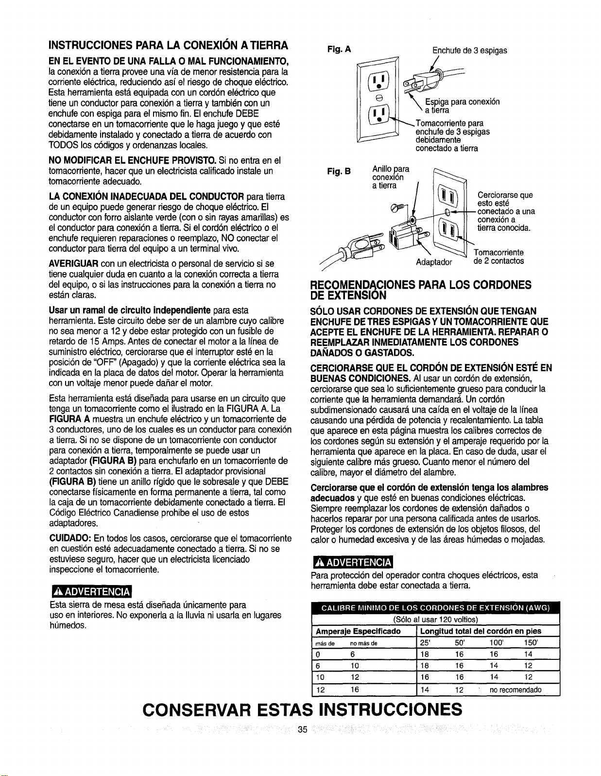
Fig. A
Enchufede 3 espigas
Espigapara conexi6n
a tlerra
Tomacorriente para
enchufe de 3espigas
debidamente
conectado atierra
"q B Anillo ara
Fi . conex_n i _-._
atierra / I _ Cerciorarse que
esto est_
--conectado auna
conexi6n a
tierraconocida.
Tomacorriente
de2 contactos
RECOMENDACIONES PARA LOS CORDONES
DE EXTENSION
SOLO USARCORDONESDE EXTENSIONQUETENGAN
ENCHUFEDETRES ESPIGASY UNTOMACORRIENTEQUE
ACEPTEEL ENCHUFEDE LA HERRAMIENTA,REPARARO
REEMPLAZARINMEDIATAMENTELOSCORDONES
DANADOSO GASTADOS.
CERCIORARSEQUEEL CORDONDE EXTENSIONESTEEN
BUENAS CONDICIONES.AI usarun cord6ndeextensi6n,
cerciorarseque seaIo suficientementegruesoparaconducirla
corrienteque laherramientademandar_.Uncord6n
subdirnensionadocausaraunacafdaen elvoltajede laIfnea
causandounaperdidadepotenciay recalentamiento.La tabla
queapareceen estapaginamuestraloscalibrescorrectosde
loscordonesseg_nsuextensi6ny elamperajerequeridopor la
herramientaqueapareceen laplaca.Encasodeduda,usarel
siguientecalibremas grueso.CuantomenorelnL_merodel
calibre,mayoreldiametrodel alarnbre.
Cerciorarseque el cordbnde extensibntenga los alambres
adecuadosy que est_enbuenascondicionesel_ctricas.
Siemprereernplazarloscordonesdeextensi6ndafladoso
hacerlosrepararporunapersonarcalificadaantesdeusarlos.
Pretegerloscordonesde extensi6nde los objetosfilosos,del
calorohumedadexcesivay de las_.reashemedasomojadas.
'!_F:llgJ=ill =_[e_!
Paraprotecciondel operadorcontra choqueselectricos,esta
herramientadebe estar conectadaa tierra.
'!_1';IIIYJ=1;tlI =1! [I,]!
Esta sierrade mesa est_ disefiada Onicamentepara
usoen interiores.Noexponerlaa la Iluviani usarla en lugares
hemedos.
_e,Y_,lIII=!-"I:11i_ll_Ilili[el I] ::11I(e_'tiKo]:t ele]_I::lk.Ri] :11_:l I ___H[e]_|F_lvivL_
($61o al usar 120 voltios)
Amperaje Especificado Longitud total del cord6n en pies
masde nom_sde 25' 50' 100' 150'
0 6 18 16 16 14
6 10 18 16 14 12
10 12 16 16 14 12
12 16 14 12 no recornendado
CONSERVAR ESTAS INSTRUCCIONES
....... 35 ....
ACCESORIOS RECOMENDADOS
Visitar el Departamentode Ferreterfade la tiendaSears mas
cercana over el Cat_.logode HerramientasEl_ctricas/Neum_.ticas
y Manualesde Searspara comprar losaccesorios recomendados
paraesta herramienta.
DESEMBALAJE Y VERIFICACION DEL
CONTENIDO
Separartodas laspiezas de sus envolturas.Antes de descartar
cualquiermaterialde embalaje,verificarlaspiezascontrala
ilustraci6nen la siguiente p_.ginay la lista a continuaci6nparaver
que esten completas.
'tV.,1elvj=l-'ti=1_[o]P
'tV_,1elvJ=1-'11=1_[_ P
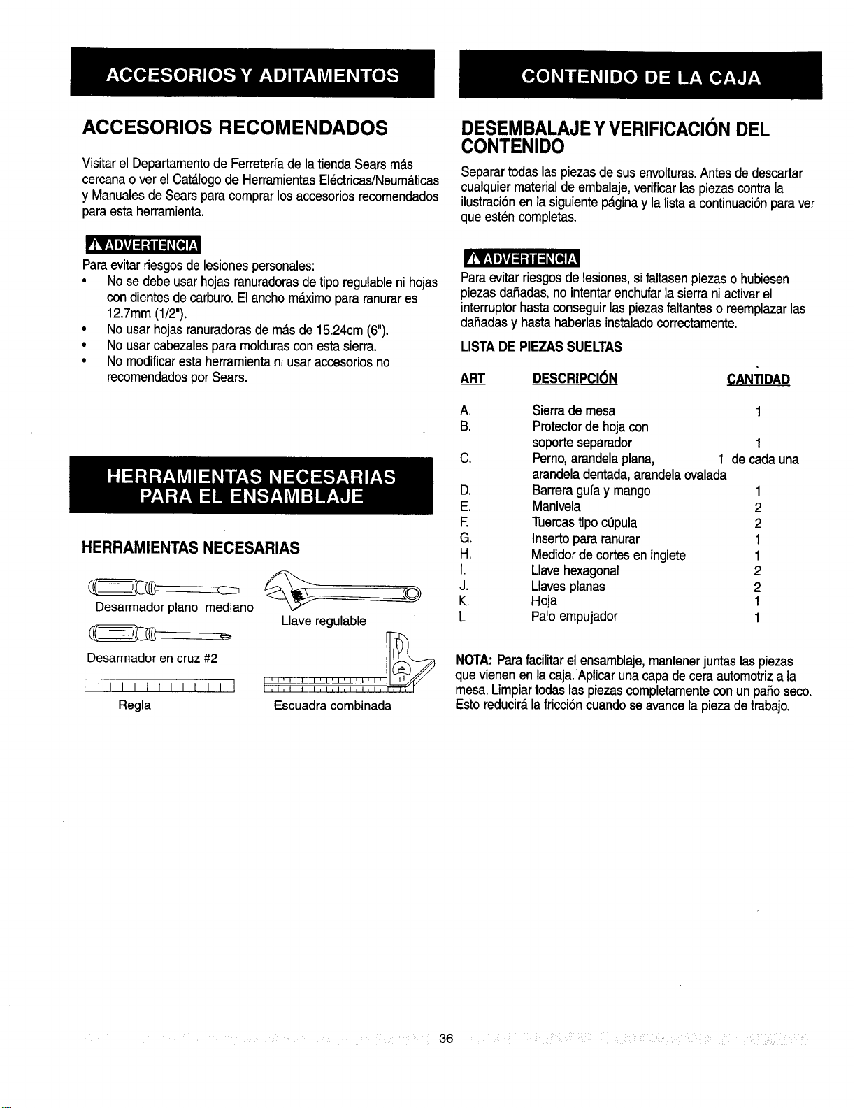
Paraevitarriesgos de lesionespersonales:
• Nose debe usarhojas ranuradorasde tipo regulableni hojas
con dientesde carburo.E1ancho m_.ximopara ranurares
12.7mm(1/2").
• No usar hojasranuradorasde m_.sde 15.24cm(6").
• No usarcabezalespara moldurascon esta sierra.
• No modificaresta herramienta ni usaraccesorios no
recomendadospor Sears.
HERRAMIENTAS NECESARIAS
Desarmador piano mediano
Desarrnador en cruz #2
[ Illl Irllt II I
Regla
Llave regulable
'l'l'l'l'l'l'l'l'l'_
TTT3 TTTTT
Escuadra combinada
Paraevitar riesgos de lesiones,sifaltasenpiezas o hubiesen
piezas daSadas,no intentarenchufarla sierrani activarel
interruptorhasta conseguirlas piezasfaltanteso reemplazarlas
daSadasy hasta haberlasinstaladocorrectamente.
LISTADE PIEZASSUELTAS
ART DESCRIPCION CANTIDAD
A. Sierrade mesa 1
B. Protectorde hoja con
soporte separador 1
C. Perno,arandelaplana, 1 de cadauna
arandeladentada, arandelaovalada
D. Barreragufa y mango 1
E. Manivela 2
E Tuercastipocopula 2
G. Insertopara ranurar 1
H. Medidorde cortesen inglete 1
I. Llavehexagonal 2
J. Llavesplanas 2
K. Hoja 1
L. Palo empujador 1
NOTA: Parafacilitarel ensamblaje,mantenerjuntas las piezas
quevienenenlacaja.Aplicarunacapadeceraautomotriza la
mesa.Limpiartodaslaspiezascompletamenteconunpasoseco.
Estoreducir__lafricci6ncuandoseavancelapiezadetrabajo.
36
.... il .... :i ?i _ ii_ i __
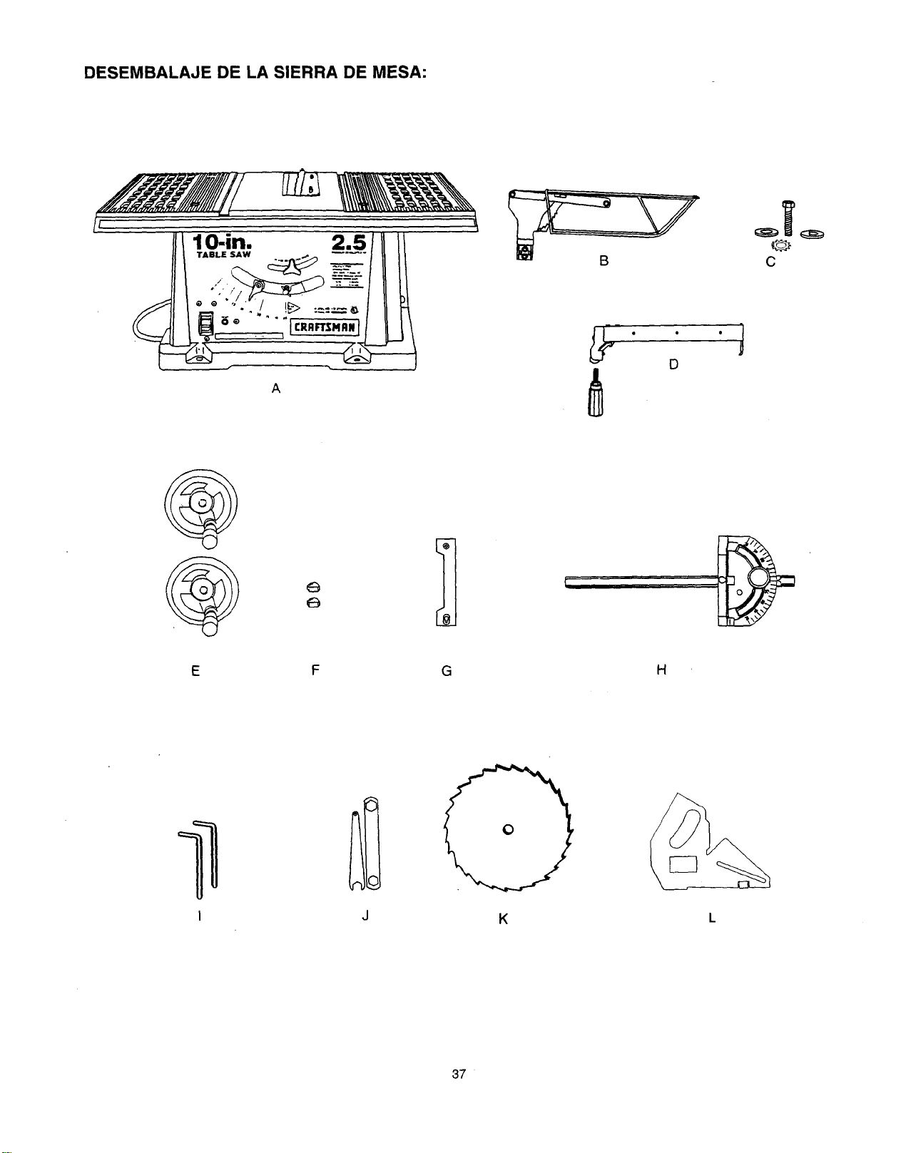
DESEMBALAJE DE LA SIERRA DE MESA:
lO.in.
A
C
6
1
F G
H
I J
K
L
37
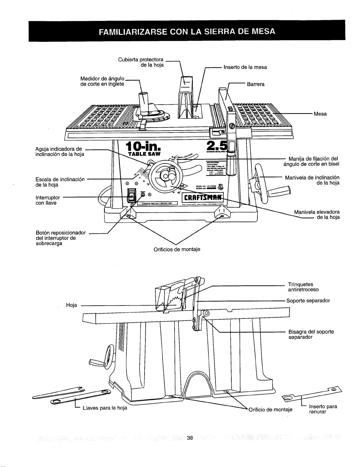
Cubierta protectora
de la hoja
Medidor de _n(
de corte en inglete
Inserto de la mesa
Barrera
Mesa
I
Aguja indicadora de
inclinaci6n de la hoja
Escala de inclinaci6n
de la hoja
Interruptor
con Ilave
Bot6n reposicionador
del interruptor de
sobrecarga
lO-in.
TABLE SAW
Manija de fijaci6n del
l _ de la hoja
=_-_ _ Manivela elevadora
_ de la hoja
Orificios de montaje
_ta hoja
Tr[nquetes
antiretroceso
Soporte separador
'/ / IBisagra del soporte
/ separador
Orifncto de mo_rPara
..... : 38
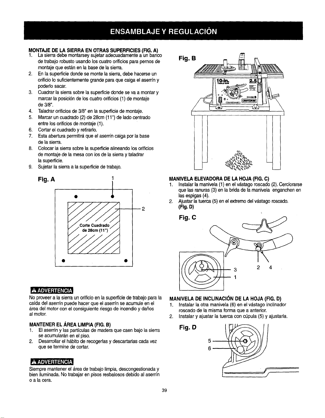
MONTAJEDE LA SIERRA EN OTRASSUPERFICIES(FIG.A)
1. Lasierradebemontarseysujetaradecuadamentea unbanco
detrabajorobustousandoloscuatroorificiosparapernosde
montajeque est_nen labase de la sierra.
2. En la superficiedonde se montela sierra,debe hacerse un
orificio Iosuficientementegrande paraque caiga el aserrfny
poderlosacar.
3. Cuadrarla sierrasobrela superficiedonde se va a montary
marcarla posici6nde loscuatroorificios(1) de montaje
de 3/8".
4. Taladrarorificiosde 3/8"en la superficiede montaje.
5. Marcar un cuadrado(2) de 28cm (11") de ladocentrado
entrelos orificiosde montaje (1).
6. Cortar el cuadradoy retirarlo.
7. Esta aberturapermitir__que el aserrfn caigapor la base
de la sierra.
8. Colocarla sierrasobrela superficiealineandolos odficios
de montaje de la mesa con los de la sierray taladrar
la supefficie.
9. Sujetarla sierraa la superficiede trabajo.
Fig. A
2
Fig. B
(
9\ 9 \_v\
MANIVELAELEVADORADE LA HOJA(FIG. C)
1. Instalarla manivela(1) en el v_.stagoroscado(2).Cerciorarse
que lasranuras(3) enlabridadela manivela enganchenen
lasespigas(4).
2. Ajustar latuerca(5) enel extremodelv_.stagoroscado.
(Fig. D)
Fig. C
3 2 4
1
'tY-_1J_vJ=1,IIi =1_[_ r,
No proveera la sierraun orificio en la supefficiede trabajopara la
caida del aserrinpuede hacerque el aserr{nseacumule en el
a.readel motorcon el consiguienteriesgode incendioy daSos
al motor.
MANTENEREL AREA LIMPIA(FIG.B)
1. El aserrin y laspartfculas de maderaque caen bajo la sierra
seacumularanen elpiso.
2. Desarrollarelh_bitode recogerlasy descartarlascadavez
queseterminedecortar.
Siempremantener el _rea de trabajolimpia,descongestionaday
bien iluminada.No trabajaren pisos resbalososdebido al aserr[n
o a la cera.
MANIVELA DE INCLINACI(_NDE LA HOJA (FIG. D)
1. Instalarla otra manivela (6) en el v_stago inclinador
roscadode la misma forma que a anterior.
2. Instalary ajustarla tuercacon copula(5) y ajustarla.
Fig. D
5
6
39
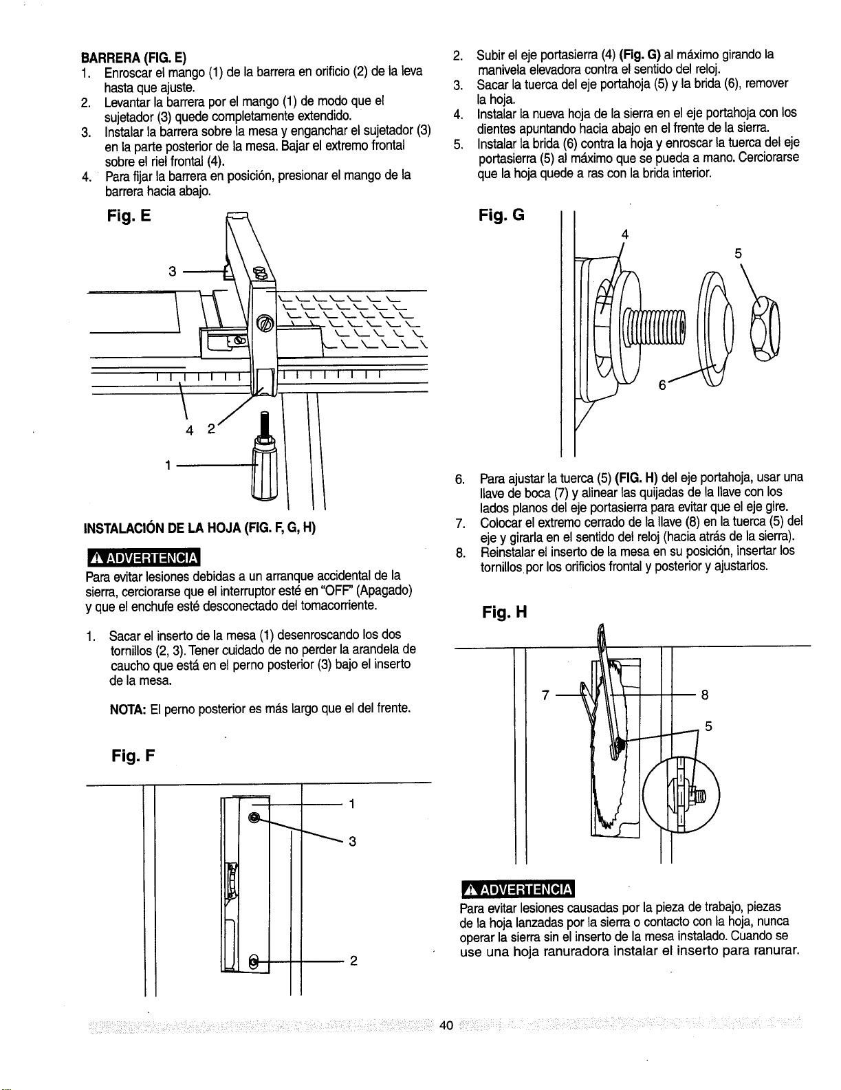
BARRERA(FIG. E)
1. Enroscarelmango(1) de labarreraen orificio(2) de la leva
hastaque ajuste.
2. Levantarla barrerapor el mango(1) de modoque el
sujetador(3) quede completamenteextendido.
3. Instalarla barrerasobre la mesa y engancharel sujetador (3)
en la parte posteriorde la mesa.Bajar el extremofrontal
sobreel rielfrontal (4).
4. Parafijar la barreraen posici6n,presionarel mangode la
barrera haciaabajo.
Fig. E
I 1
4
1
i
INSTALACIONDELA HOJA (FIG. F,G, H)
iVA111Yj:_itI_[o]1
Paraevitar lesionesdebidasa un arranqueaccidentalde la
sierra,cerciorarseque el interruptorest_ en "OFF"(Apagado)
y que el enchufeeste desconectadodel tomacorriente.
,
Sacarel insertode la mesa (1) desenroscandolosdos
tornillos (2,3).Tenercuidadode no perderla arandelade
caucho que esta en el perno posterior(3) bajo el inserto
de la mesa.
NOTA:El perno posteriores mas largo que el del frente.
Fig. F
2. Subir el eje portasierra (4) (Fig.G) al mdximogirando la
manivelaelevadoracontra el sentido del reloj.
3. Sacar la tuerca del eje portahoja(5)y la brida (6),remover
la hoja.
4. Instalarla nuevahoja de la sierraen el eje portahojacon los
dientes apuntandohaciaabajo en el frente de la sierra.
5. Instalarlabrida (6) contra la hojay enroscar la tuercadel eje
portasierra(5) al mdximoque se pueda a mano.Cerciorarse
que la hoja quede a rascon la brida interior.
Fig. G
5
6. Paraajustar la tuerca(5)(FIG. H)del eje portahoja,usaruna
Ilavede boca(7) y alinear lasquijadasde la liavecon los
ladospianosdel eje portasierraparaevitar que el eje gire.
7. Colocarel extremocerradode la Ilave(8) en la tuerca (5) del
eje y girarlaen el sentido del reloj (haciaatr_.sde la sierra).
8. Reinstalarel inserto de la mesa en su posici6n,insertarlos
tornillos por losorificiosfrontaly posteriory ajustarlos.
Fig. H
8
5
1
!V.,J livj €1-']11€1_[o]I
Paraevitar lesionescausadaspor la pieza de trabajo,piezas
de la hoja lanzadaspor la sierrao contactocon la hoja,nunca
operar la sierrasinel insertode la mesa instalado.Cuandose
use una hoja ranuradora instalar el inserto para ranurar.
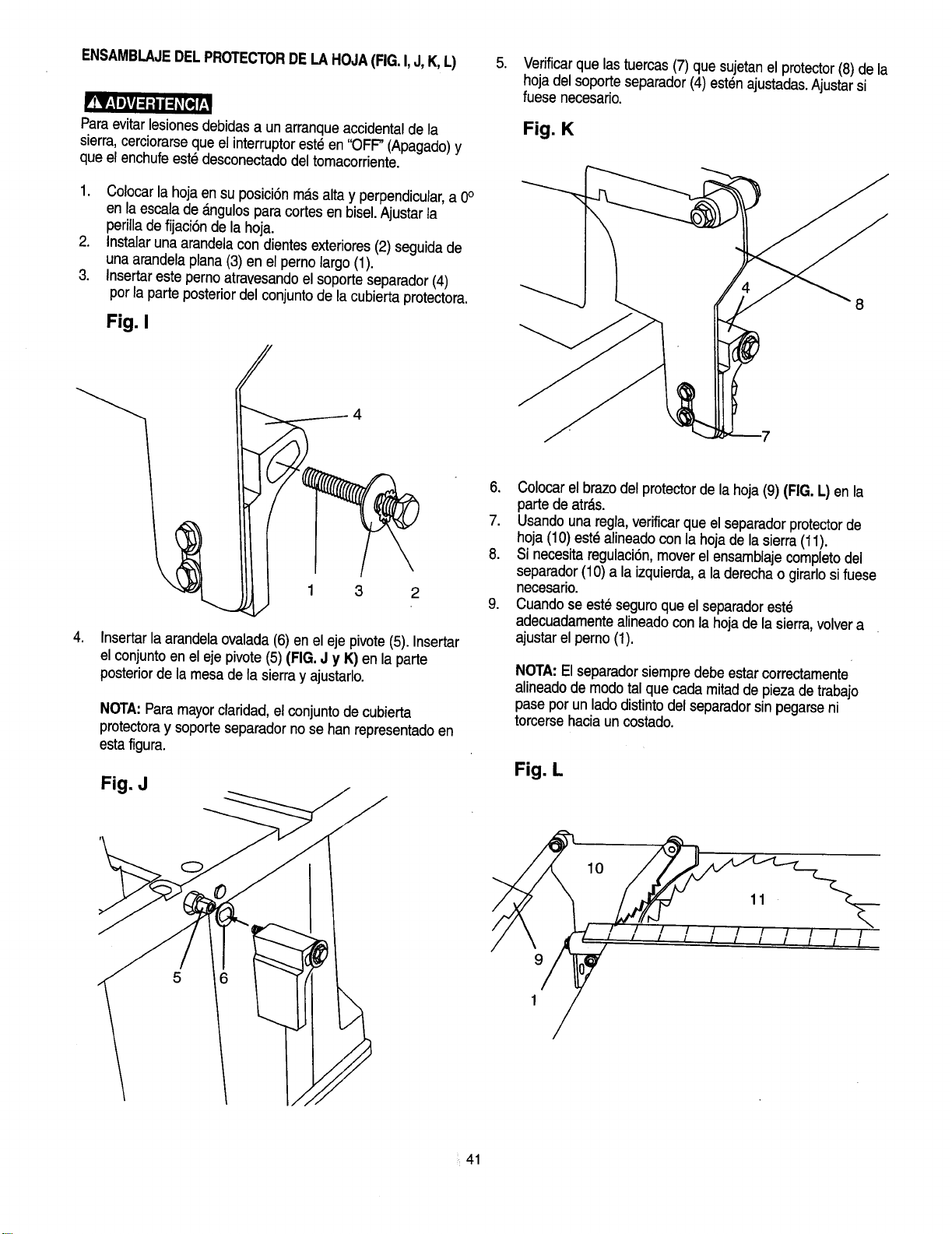
ENSAMBLAJEDELPROTECTORDELAHOJA(FIG.I,J,K,L)
'IV;Ill,J: :ii=_ [qW
Paraevitar lesionesdebidasa un arranqueaccidentalde la
sierra,cerciorarseque el interruptorest_ en "OFF"(Apagado)y
que el enchufeest_ desconectadodel tomacorriente.
1. Colocar la hoia en su posici6n rn_.saltay perpendicular,a 0°
en la escalade _.ngulospara cortes en bisel.Ajustar la
perillade fijaci6n de la hoja.
2. Instalaruna arandela condientes exteriores(2) seguidade
unaarandela plana (3) en el perno largo (1).
3. Insertareste pernoatravesandoel soporte separador(4)
por la parteposterior del conjuntode la cubierta protectora.
Fig. I
1 3 2
,
Insertarla arandelaovalada(6) en el eje pivote (5). Insertar
el conjunto en el eje pivote (5) (FIG.J y K) en la parte
posteriorde la mesa de la sierray ajustarlo.
NOTA:Para mayorclaridad,el conjuntode cubierta
protectoray soporteseparador nose han representadoen
esta figura.
Fig. J
.
Verificarque lastuercas(7) que sujetanel protector(8)de la
hoja del soporte separador(4) est6n ajustadas.Ajustar si
fuese necesario.
Fig. K
8
6. Colocarel brazodel protectorde la hoja(9) (FIG. L)en la
parte de atrds.
7. Usando una regla,verificarque el separadorprotectorde
hoja (10) est_ alineadocon la hoja de la sierra(11).
8. Si necesitaregulaci6n,mover el ensamblajecompletodel
separador(10) a la izquierda,a la derechao girarlosi fuese
necesario.
9. Cuandose este seguroque el separadorestd
adecuadamentealineado conla hojade la sierra,volvera
ajustar el perno (1).
NOTA:El separadorsiempre debe estarcorrectamente
alineadodernodotalque cadamitad depiezadetrabajo
paseporun ladodistintodel separadorsinpegarseni
torcersehaciauncostado
Fig L
10
9
1
_ 41
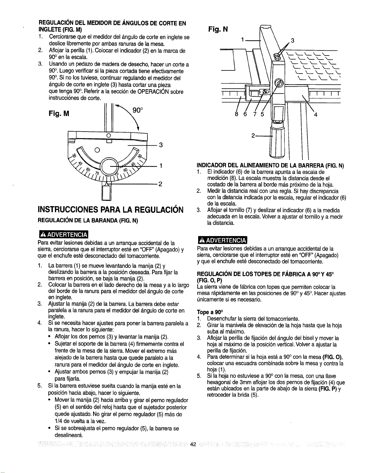
REGULACIONDELMEDIDOR DEANGULOS DE CORTEEN
INGLETE(FIG.M)
1, Cerciorarsequeel medidordel angulo decorteen ingletese
deslicelibrementeporambasranurasde lamesa.
2. Aflojarla perilla (1).Colocarel indicador(2) en la marca de
900en la escala.
3. Usando un pedazode maderade desecho,hacerun corte a
90°. Luego verificarsi la piezacortada tieneefectivamente
90°. Si no lostuviese,continuar regulandoel medidordel
_.ngulode corte en inglete(3) hasta cortar una pieza
que tenga 90°. Referira la secci6nde OPERACIONsobre
instrucci6nesde corte.
Fig. M
Li ,o,
3
INSTRUCCIONES PARA LA REGULACION
REGULACIONDE LA BARANDA(FIG. N)
Fig. N
I I
lu
IIi
8675
2_
m k_.._k__ ___ k_ ___
k._ k__ _ k_.. X_
k__ ___ X__X_.'
-- 777T
! \4
INDICADORDEL ALINEAMIENTODE LA BARRERA(FIG.N)
1. El indicador(6) de la barreraapuntaa la escalade
medici6n(8).La escala muestrala distanciadesdeel
costadode la barreraal borde m_.spr6ximode la hoja.
2. Medirla distanciareal con una regla.Si haydiscrepancia
conla distanciaindicadapor la escala,regularel indicador(6)
de la escala.
3. Aflojarel tornillo(7) y deslizarel indicador(6) a la medida
adecuadaen la escala.Volvera ajustarel tornilloy a medir
la distancia.
!VAliill :Ill i _ _[flI
Paraevitar lesionesdebidasa un arranqueaccidentalde la
sierra,cerciorarseque el interruptoreste en "OFF"(Apagado)y
que el enchufe estedesconectadodel tomacorriente.
1. La barrera (1) semueve tevantandola manija(2) y
deslizandola barreraa la posici6n deseada.Parafijar la
barreraen posici6n,se baja la manija (2).
2. Colocar la barreraen el ladoderecho de la mesa y a Iolargo
del borde de la ranura parael medidordel _.ngulode corte
en inglete.
3. Ajustar la manija(2) de la barrera.La barreradebe estar
paralelaa la ranurapara el medidordel dngulo de corte en
inglete.
4. Si se necesitahacerajustespara poner la barrera paralelaa
la ranura,hacerIosiguiente:
• Aflojar losdos pernos(3) y levantarla manija(2).
• Sujetarel soportede la barrera (4) firmementecontra el
frente de la mesa de la sierra. Moverel extremom_.s
alejado de la barrerahasta que quede paraleloa la
ranurapara el medidordel _.ngulode corte en inglete.
• Ajustar ambos pernos (3)y empujar la manija(2)
para fijarla.
5. Si la barreraestuviese sueltacuando la manijaeste en la
posici6n haciaabajo,hacerIo siguiente.
• Moverla manija (2) haciaarribay girar el perno regulador
(5) en el sentidodel reloj hastaque el sujetadorposterior
quede ajustado.No girarel perno regulador (5) ma.sde
1/4de vuelta a la vez.
• Si se sobreajustael perno regulador(5),la barrera se
desalineara.
Paraevitar lesionesdebidasa un arranqueaccidentalde la
sierra,cerciorarseque el interruptoresteen "OFF"(Apagado)
y que el enchufeest_ desconectadodel tomacorriente.
REGULACI(3NDE LOSTOPESDE FABRICAA90°Y 450
(FIG.O,P)
Lasierravienedef_.bricacontopesque permitencoIocarla
mesar_.pidamenteen lasposicionesde90° y 45°. Hacerajustes
t_nicamentesi es necesario.
Topea 90°
1. Desenchufarla sierradel tomacorriente.
2. Girar la manivelade elevaci6nde la hoja hasta que la hoja
suba al m_.ximo.
3. Aflojarla perilladefijaci6n del _.ngulodel bisely moverla
hojaal m&ximode la posici6nvertical.Volvera ajustar la
perilla de fijaci6n.
4. Paradeterminarsi lahoja est_ a 90° con la mesa (FIG.O),
colocar una escuadracombinadasobre la mesay contra la
hoja (1).
5. Si la hoja no estuviesea 900con la mesa,con una Ilave
hexagonalde 3mm aflojar losdospernos de fijaci6n(4) que
est_.nubicados en la parte de abajo de la sierra(FIG.P) y
retrocederla brida (5).
7iii!_ili!iiii_i!!:LL:_!i_i!:iiiiLiil; _:,iii! !!iiiii i i!i!;ii;i!¸ill!ill _i_:ii::!ii!iliiiiiiiiiiiiiliif!ii?i!ii_:i;!i_;i!ii_i 42 , ili_il i iii¸ ! i_ii iiiii!ii!iiiii_::i/ i¸¸ ': _iL_L i? i! ¸
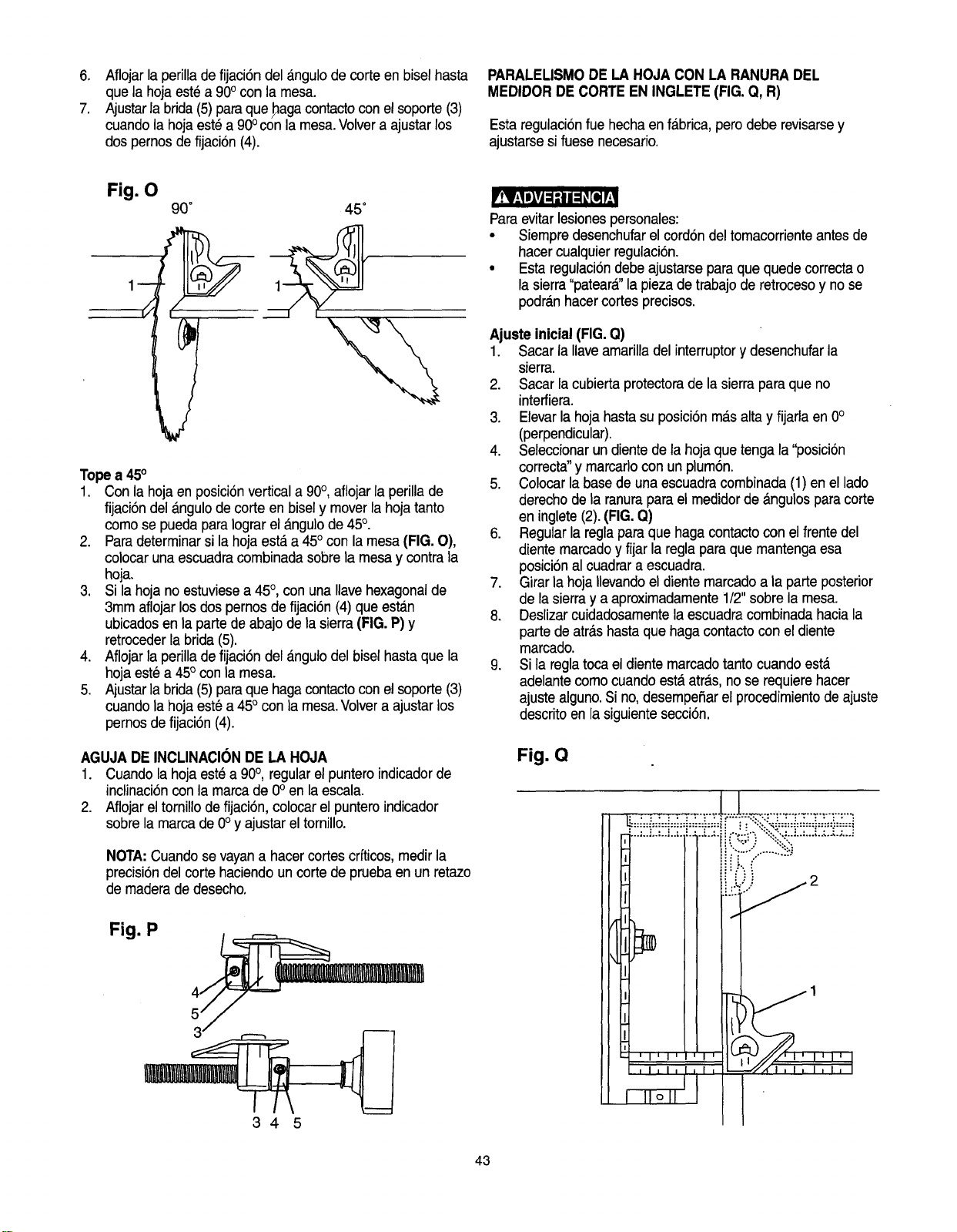
6. Aflojar la perillade fijaci6n del angulode corte en bisel hasta
que la hoja est_a 900con la mesa.
7. Ajustarlabrida(5) paraque_aga contactocon el soporte(3)
cuandola hojaeste a 90°con la mesa.Volvera ajustar los
dos pernosde fijaci6n (4).
PARALELISMODE LA HOJACON LA RANURA DEL
MEDIDORDE CORTEEN INGLETE(FIG.Q, R)
Esta regulaci6nfuehechaen fabrica,pero debe revisarsey
ajustarsesi fuese necesario.
Fig. O
90= 45 =
1
Tope a 45°
1. Conla hojaen posici6nverticala 90°, aflojar la perilla de
fijaci6n del dngulo de corte en bisely moverla hoja tanto
como se pueda paraIograrel _.ngulode 45°.
2. Paradeterminarsi la hoja est,. a 45° con la mesa(FIG. O),
colocaruna escuadracombinada sobrela mesay contra la
hoja.
3. Si la hoja no estuviesea 45°,con una Ilavehexagonalde
3mm aflojarlos dospernosde fijaci6n(4) que estan
ubicadosen la partede abajo de la sierra(FIG.P) y
retrocederla brida (5).
4. Aflojarla perilla de fijaci6n del angulodel biselhasta que la
hoja este a 45° con la mesa.
5. Ajustarla brida(5) paraque haga contactocon el soporte(3)
cuandola hoja estea 45° con la mesa.Volvera ajustarlos
pernosde fijaci6n (4).
AGUJADE INCLINACIONDE LA HOJA
1. Cuando la hoja est_ a 90°, regular el punteroindicadorde
inclinaci6ncon la marcade 0° en la escala.
2. Aflojarel tornillo de fijaci6n,colocarel punteroindicador
sobrela marca de 0° y ajustarel tornillo.
NOTA:Cuandosevayana hacercortes crfticos,medir la
precisi6ndel corte haciendoun corte de pruebaen un retazo
de maderade desecho.
.
345
Paraevitar lesionespersonales:
• Siempredesenchufarel cord6n del tomacorrienteantes de
hacercualquierregulaci6n.
• Esta regulaci6ndebeajustarsepara que quede correctao
la sierra"pateara"la piezade trabajode retrocesoy no se
podra.nhacercortes precisos.
Ajusteinicial(FIG.Q)
1. Sacar la Ilaveamarilladel interruptorydesenchufarla
sierra.
2. Sacar la cubierta protectorade la sierrapara que no
interfiera.
3. Elevarla hojahasta su posici6n m_.salta y fijarlaen 0°
(perpendicular).
4. Seleccionarun diente de la hoja que tenga la "posici6n
correcta"y marcarlocon un plum6n.
5. Colocar la basede una escuadracombinada (1) en el lado
derecho de la ranurapara el medidorde angulospara corte
en inglete(2).(FIG. Q)
6. Regularlaregla paraque haga contactocon el frentedel
diente marcadoy fijarla regla paraque mantengaesa
posici6nal cuadrara escuadra.
7. Girarla hoja Ilevandoel diente marcadoa la parte posterior
de la sierray a aproximadamente1/2"sobre la mesa.
8. Deslizarcuidadosamentela escuadracombinada haciala
parte de atras hastaque haga contacto con el diente
marcado.
9. Sila reglatoca el diente marcadotanto cuandoest_
adelantecomocuando est,.atr_.s,no se requierehacer
ajustealguno.Si no,desempeSarel procedimientode ajuste
descritoen lasiguiente secci6n.
Fig. Q
43
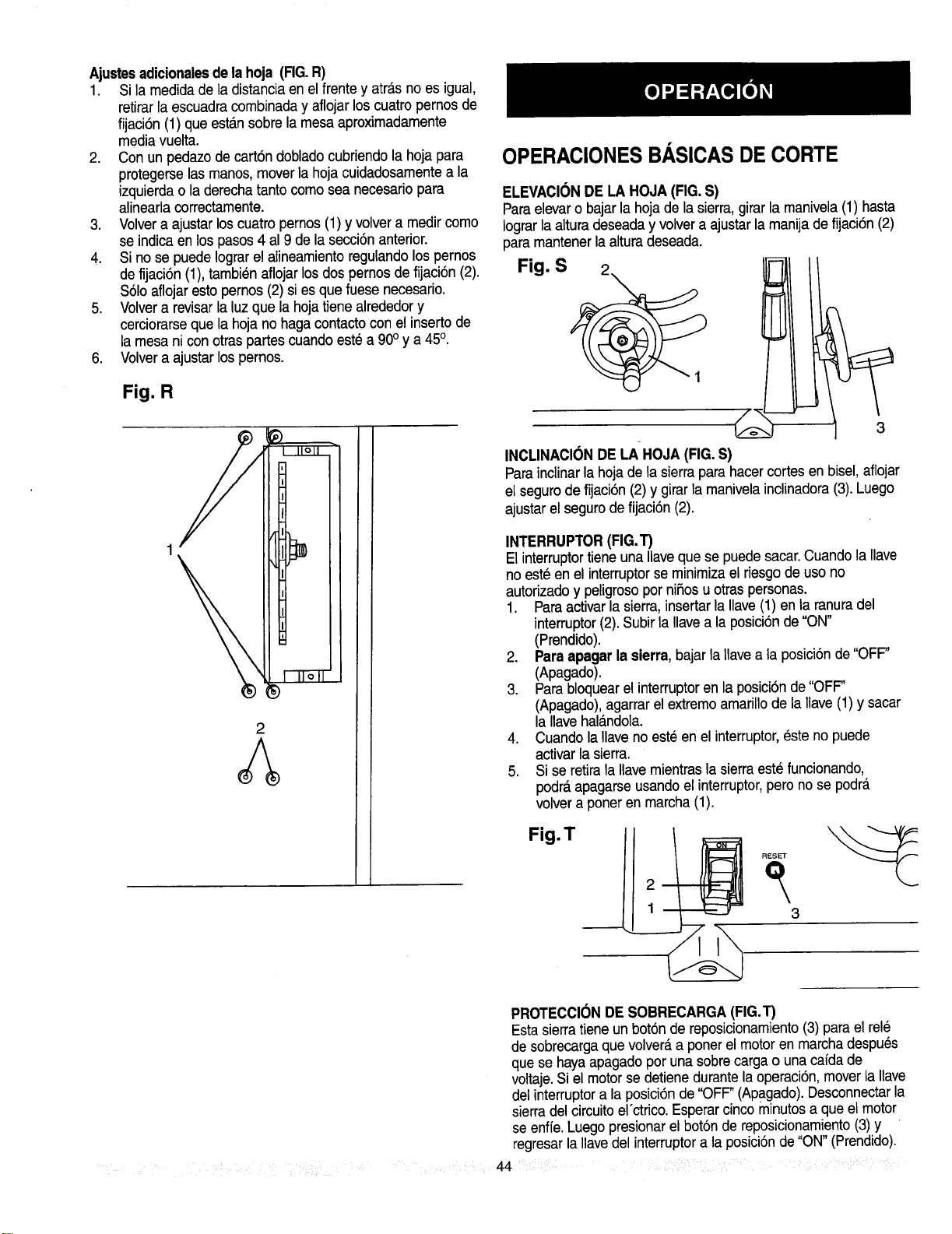
Ajustesadicionalesdelahoja (FIG.R)
1. Si la medidade la distanciaen el frente y atra_sno es igual,
retirarlaescuadracombinaday aflojarloscuatropernosde
fijaci6n (1) que esta.nsobrelamesaaproximadamente
mediavuelta.
2. Con unpedazodecart6ndobladocubriendola hojapara
protegerselasmanos,moverlahoja cuidadosamentea la
izquierdaola derechatantocomosea necesariopara
alinearlacorrectamente.
3. Volvera ajustarloscuatropemos(1) y volvera medircomo
se indicaenlospasos4 al9 de lasecci6n anterior.
4. Sinose puedeIograrel alineamientoregulandolospernos
defijaci6n (1),tambi_naflojarlosdospernos defijaci6n(2).
$61oaflojarestopernos(2) si esque fuese necesario.
5. Volvera revisarlaluzque lahojatienealrededory
cerciorarsequela hojanohagacontactoconelinsertode
la mesani conotraspartescuandoestea 90° y a 45°.
6. Volvera ajustarlospernos.
Fig. R
2
OPERACIONES BASICAS DE CORTE
ELEVACIONDE LA HOJA(FIG.S)
Paraelevaro bajar la hoja de la sierra,girarla manivela(1) hasta
Iograrlaalturadeseaday volvera ajustarlamanijade fijaci6n(2)
paramantenerlaalturadeseada.
Fig. S
INCLINAClONDE LA HOJA (FIG.S)
Parainclinarla hojade la sierraparahacercortesenbisel,aflojar
elsegurodefijaci6n (2) y girarlamanivelainclinadora(3).Luego
ajustarel segurodefijaci6n (2).
INTERRUPTOR(FIG.T)
El interruptortieneuna Ilaveque se puedesacar.Cuandola Ilave
no est_ en el interruptorse minimizael riesgode uso no
autorizado y peligrosopor niSosu otras personas.
1. Paraactivarla sierra,insertar la Ilave(1) en la ranura del
interruptor(2).Subirla Ilavea laposici6n de "ON"
(Prendido).
2. Para apagarla sierra,bajar la Ilavea la posici6n de"OFF"
(Apagado).
3. Para bloquearel interruptoren la posici6nde "OFF"
(Apagado),agarrarel extremoamarillode la llave(1) y sacar
la Ilavehala.ndola.
4. Cuando la Ilaveno este en el interruptor,_ste no puede
activar la sierra.
5. Si se retirala Ilavemientrasla sierraeste funcionando,
podr_,apagarseusandoel interruptor,pero no se podr_.
volvera porteren marcha(1).
Fig.T
RESET
3
i ¸¸
PROTECCI(_NDE SOBRECARGA(FIG.T)
Esta sierratieneun bot6n de reposicionamiento(3) para el rele
desobrecargaquevolver_,a ponerelmotor enmarchadespu_s
quese hayaapagadoporunasobrecargao unacafdade
voltaje.Siel motorse detienedurantelaoperaci6n,mover la Ilave
delinterruptora laposici6nde"OFF"(APagado).Desconnectarla
sierradelcircuitoel'ctrico.Esperarcincominutosa queelmotor
seenfie.Luegopresionarel bot6nde reposicionamiento(3) y
regresarlaIlavedel interruptora la posici6nde "ON"(Prendido).
44
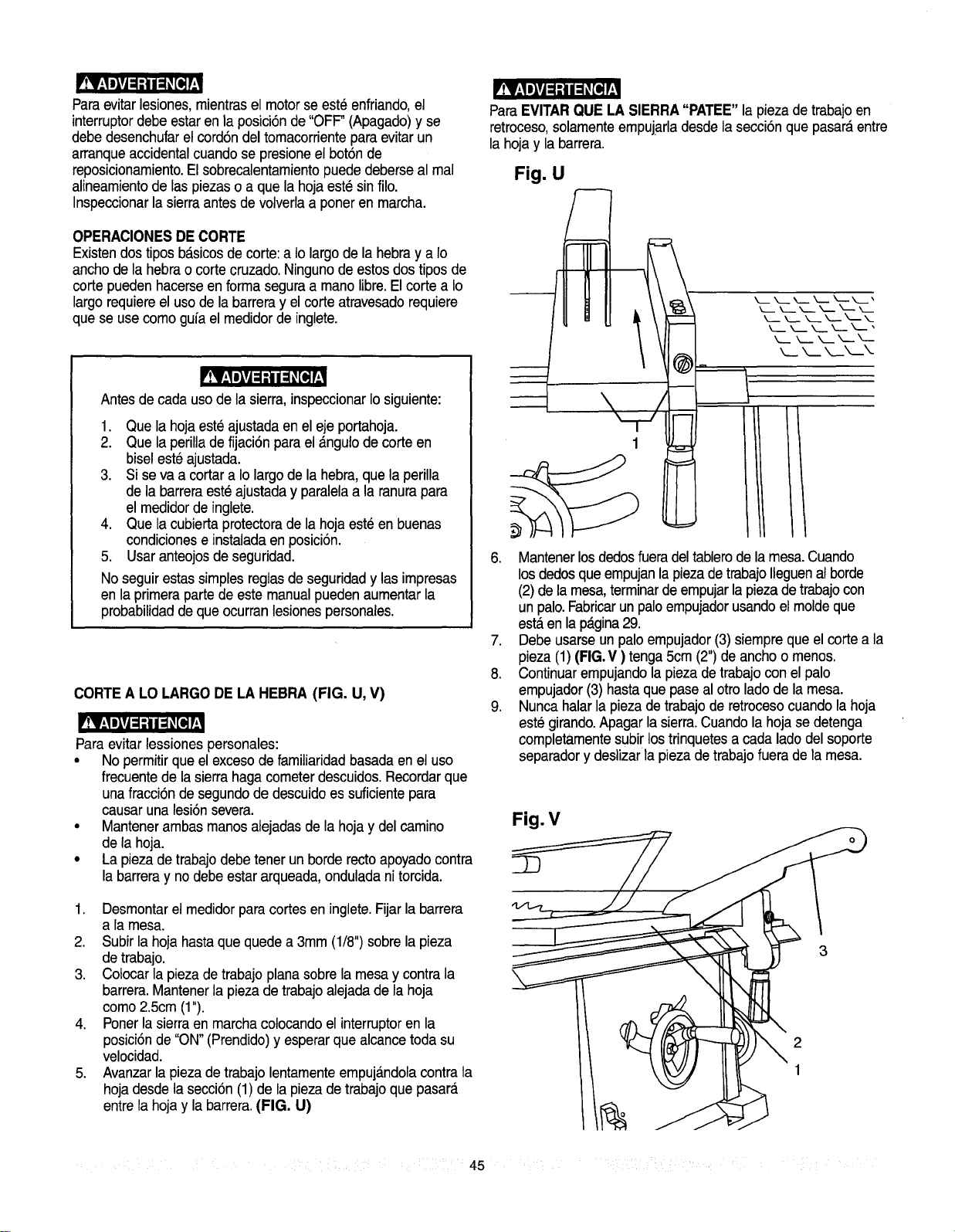
'!V__lilvl ='1 / :_ [1_[
Paraevitarlesiones,mientrasel motorse est_ enfriando,el
interruptordebe estar en la posici6nde "OFF"(Apagado)y se
debe desenchufarel cord6ndel tomacorrienteparaevitar un
arranqueaccidentalcuandose presioneelbot6nde
reposicionamiento.El sobrecalentamientopuede deberseal real
alineamientode laspiezaso aque la hoja est6 sinfilo.
Inspeccionarla sierraantesde volverlaa poner en marcha.
OPERACIONESDECORTE
Existendostipos b_.sicosde corte:a Iolargo de la hebray a Io
anchodela hebrao corte cruzado.Ningunode estosdostipos de
cortepuedenhacerseenforma seguraa manolibre.Elcortea Io
largorequiereelusodelabarreray elcorteatravesadorequiere
quese usecomogufael medidordeinglete.
Antes de cadauso de la sierra, inspeccionarIosiguiente:
1. Que la hojaeste ajustada en el eje portahoja.
2. Que la perillade fijaci6n para el _.ngulodecorte en
biseleste ajustada.
3. Si se va a cortar a Iolargo de la hebra,que la perilla
de la barreraeste ajustaday paralelaala ranurapara
el medidorde inglete.
4. Que la cubierta protectorade la hoja est_ en buenas
condicionese instaladaen posici6n.
5. Usar anteojosde seguridad.
No seguirestassimplesreglasde seguridady las impresas
en la primerapartede este manualpuedenaumentar la
probabilidadde que ocurranlesionespersonales.
CORTEA LO LARGODE LA HEBRA (FIG. U, V)
Para evitar lessiones personales:
• Nopermitir que el excesode familiaridadbasadaen el uso
frecuentede la sierrahaga cometerdescuidos.Recordarque
una fracci6nde segundode descuidoes suficientepara
causar una lesi6nsevera.
• Mantenerambas manosalejadasde la hoja y del camino
de la hoja.
• La piezade trabajodebe tener un borde recto apoyadocontra
la barreray no debe estararqueada,ondulada ni torcida.
1. Desmontarel medidorpara cortes en inglete.Fijarla barrera
a la mesa.
2. Subir la hoja hasta que quede a 3mm (1/8") sobrela pieza
de trabajo.
3. Cotocarla piezade trabajo planasobre la mesay contra la
barrera.Mantenerla piezade trabajoalejada de la hoja
como 2.5cm (1").
4. Ponerla sierraen marchacolocando el interruptoren la
posici6nde "ON"(Prendido)y esperarque alcancetoda su
velocidad.
5. Avanzarla piezade trabajolentamenteempuj_.ndolacontra la
hojadesde la secci6n(1) de la piezade trabajoque pasar_.
entrela hoja y la barrera.(FIG. U)
ParaEVITARQUE LA SIERRA"PATEE" la piezade trabajoen
retroceso,solamenteempujarladesdela secci6n que pasaraentre
la hoja y la barrera.
Fig. U
I
1
___ k. k__ k,._
k__._ k._k_k.
6. Mantenerlosdedosfueradel tablerode la mesa.Cuando
losdedosque empujanla piezade trabajoIleguenal borde
(2)de la mesa,terminarde empujarla piezadetrabajocon
un palo.Fabricarun paloempujadorusandoel moldeque
est,.en la p_.gina29.
7. Debeusarse un palo empujador(3)siempre que el corte a la
pieza(1) (FIG.V ) tenga5cm (2")de anchoo menos.
8. Continuarempujandola piezade trabajocon el palo
empujador(3) hastaque pase al otro ladode la mesa.
9. Nunca halar la piezade trabajode retrocesocuandola hoja
este girando.Apagar la sierra.Cuandola hoja se detenga
completamentesubirlostrinquetesa cadalado del soporte
separadory deslizar la pieza de trabajofuera de la mesa.
Fig. V
2
1
45
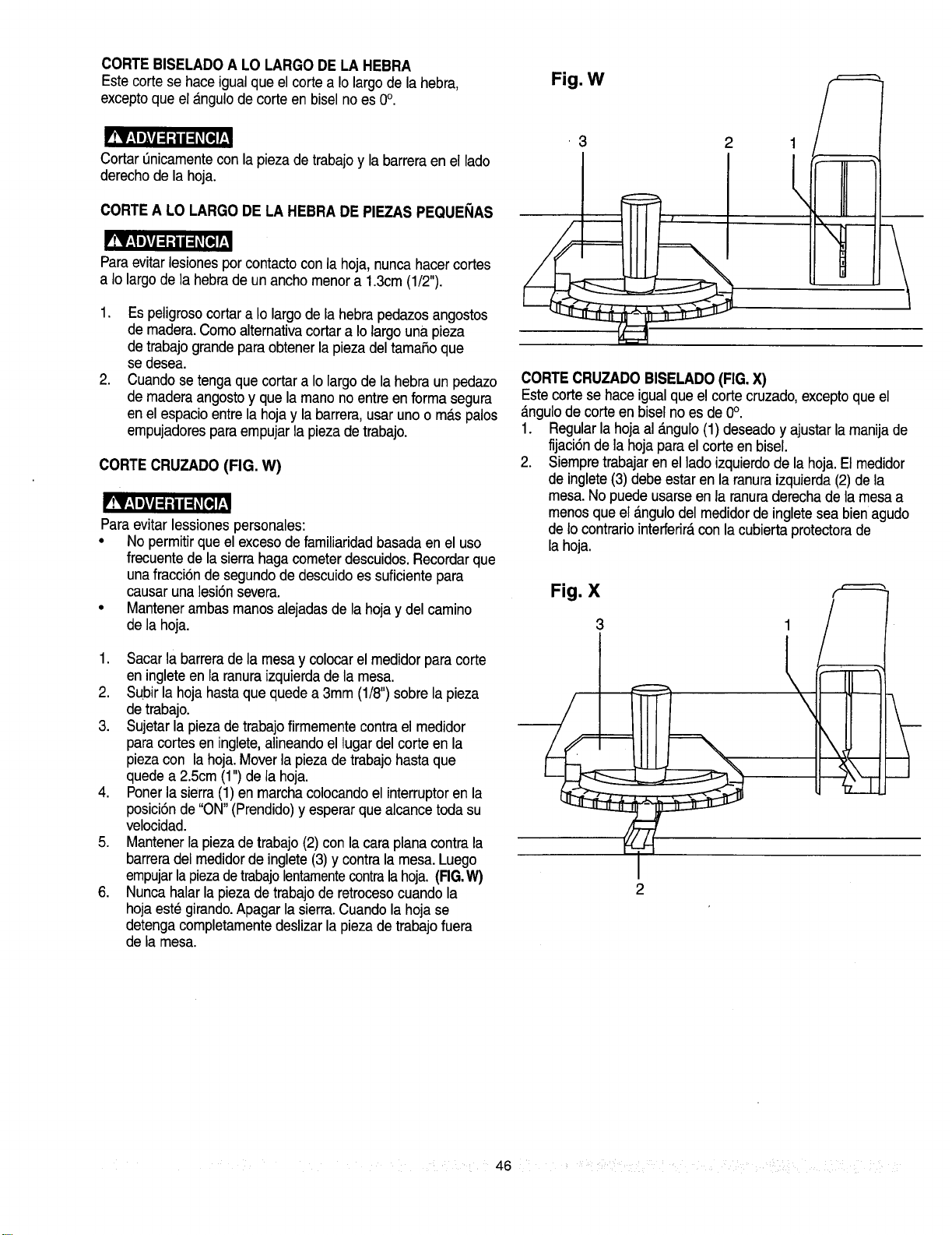
CORTEBISELADOA LO LARGODELA HEBRA
Este cortese haceigualqueelcortea Iolargodela hebra,
exceptoqueel a.ngulodecorteenbiselno es0°.
'!Y;lllll: ;I i: _[e_I
Cortar enicamentecon la piezade trabajoy la barreraen el lado
derechode la hoja.
CORTEA LO LARGODE LA HEBRA DE PIEZASPEQUEI;IAS
'!V;lllvl: :l i: _[e_I
Paraevitar lesionespor contactocon ia hoja,nuncahacercortes
a Iolargode la hebra de un ancho menora 13cm (1/2").
1. Es peligrosocortar a Iolargo de la hebra pedazosangostos
de madera.Como alternativacortar a Iolargo una pieza
de trabajograndepara obtenerla pieza del tamaSoque
sedesea.
2 Cuandosetenga que cortar a Io largode la hebra un pedazo
de maderaangostoy que la manono entre en forma segura
en el espacio entrela hoja y la barrera,usar uno o m_s palos
empujadorespara empujarla piezade trabajo.
CORTECRUZADO (FIG. W)
'!_AIIlvA: ;I /: _[e_r.
Paraevitar lessionespersonales:
• No permitirque el excesode familiaridadbasada en el uso
frecuentede la sierra hagacometerdescuidos.Recordarque
una fracci6nde segundode descuido essuficiente para
causar una lesi6nsevera.
• Mantenerambas manos alejadasde la hoja y del camino
de la hoja.
1 Sacarla barreradela mesay colocar el medidorpara corte
en ingleteen la ranuraizquierdade la mesa
2 Subir la hoja hasta que quedea 3mm (1/8")sobre la pieza
de trabajo.
3. Sujetarla pieza de trabajofirmemente contrael medidor
para cortesen inglete,alineandoel lugar del corte en la
piezacon la hoja Moverla piezade trabajo hastaque
quede a 2.5cm (1")de la hoja
4 Ponerla sierra(1) en marchacolocando el interruptoren la
posici6nde "ON"(Prendido)y esperarque alcance todasu
velocidad.
5 Mantenerla piezade trabajo (2) con la caraplana contra la
barreradel medidorde inglete(3)y contrala mesa. Luego
empujarlapiezadetrabajolentamentecontralahoja. (FIG.
6. Nunca halar la piezade trabajode retrocesocuando la
hoja est_ girando.Apagar la sierra.Cuando la hoja se
detengacompletamentedeslizarla piezade trabajo fuera
de la mesa
Fig. W
3 2
1
/=
CORTECRUZADO BISELADO(FIG.X)
Este corte se haceigual que el corte cruzado,exceptoque el
_.ngulode corteenbiselnoes de 0°.
1. Regularlahoja al_.ngulo(1) deseadoy ajustarlamanijade
fijaci6ndela hojaparaelcorteenbisel.
2. Siempretrabajaren elladoizquierdode lahoja.Elmedidor
deinglete(3) debeestarenlaranuraizquierda(2)de la
mesa.Nopuedeusarseen laranuraderechade lamesa a
menosqueel __ngulodel medidorde ingleteseabienagudo
deIocontrariointerferir_,conlacubiertaprotectorade
lahoja.
Fig. X
2
46 ;LL ¸ :
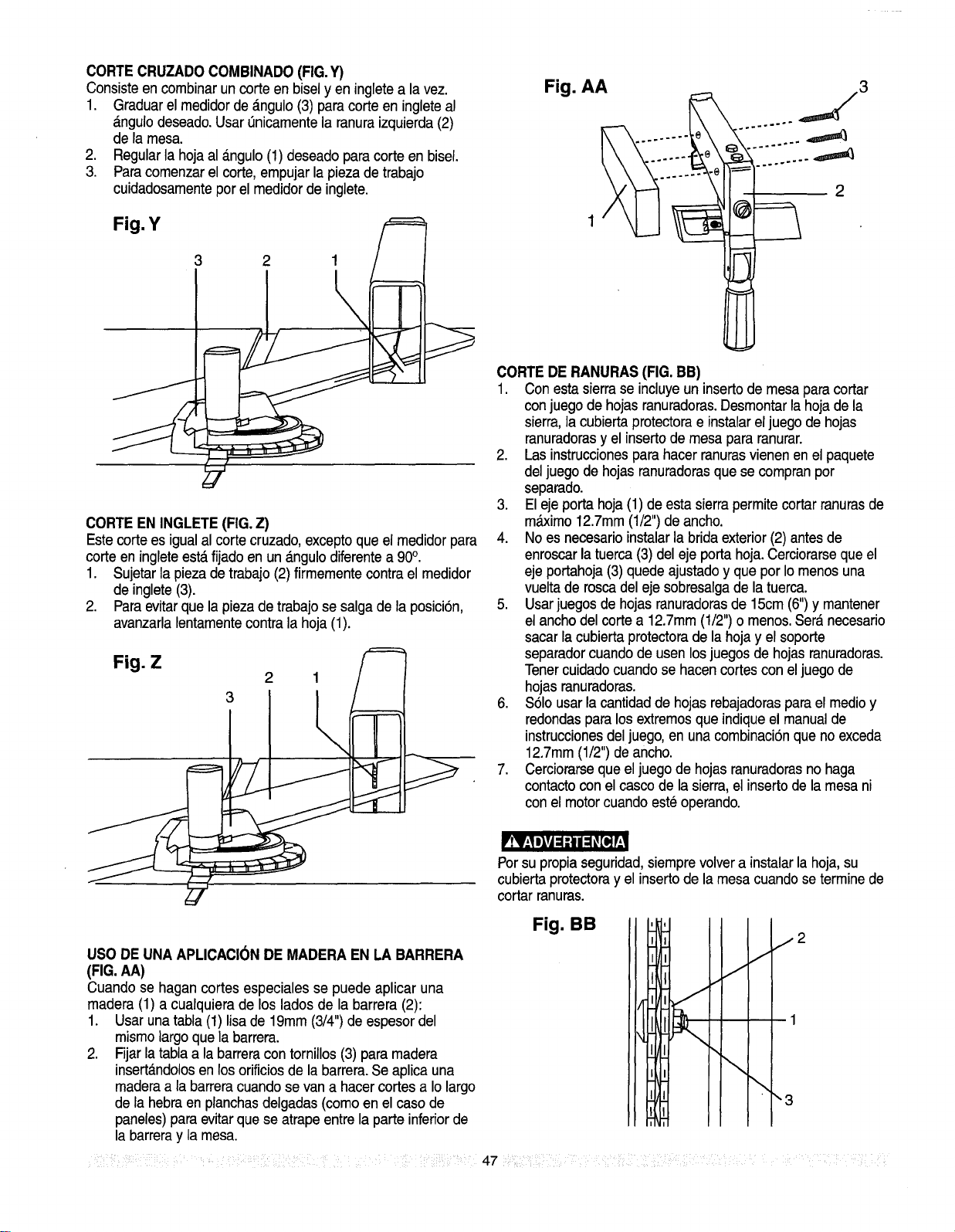
CORTECRUZADOCOMBINADO(FIG.Y)
Consisteen combinar un corte en biselyen ingletea la vez.
1. Graduarelmedidorde_ngulo (3) paracorteen ingleteal
_.ngulodeseado.Usarenicamentelaranuraizquierda(2)
dela mesa.
2. Regularlahojaal _.ngulo(1) deseadoparacorteenbisel.
3. Paracomenzarel corte,empujarlapiezadetrabajo
cuidadosamenteper elmedidordeinglete.
Fig. Y
3 2 1
CORTEEN INGLETE(FIG.Z)
Estecorte es igual al corte cruzado,exceptoque el medidorpara
corte en ingleteest,.fijado en un _.ngulodiferentea 90°.
1. Sujetarla piezade trabajo(2) firmementecontra el medidor
de inglete(3).
2. Paraevitarque la piezade trabajose salgade la posici6n,
avanzarla lentamentecontra la hoja (1).
Fig. Z
2 1
Fig. AA j3
I
2
1
CORTEDE RANURAS(FIG. BB)
1. Con esta sierrase incluyeun insertode mesapara cortar
conjuego de hojasranuradoras.Desmontarla hojade la
sierra, ia cubierta protectorae instalarel juego de hojas
ranuradorasy el insertode mesa para ranurar.
2. Las instruccionespara hacerranurasvienenen el paquete
del juego de hojasranuradorasque se compranpor
separado.
3. Eleje porta hoja(1) de esta sierrapermitecortar ranurasde
m_imo 12.7mm(1/2") de ancho.
4. Noes necesarioinstalar la brida exterior(2) antes de
enroscar la tuerca (3) del eje porta hoja.Cerciorarseque el
eje portahoja(3) quede ajustadoy que por Iomenos una
vuelta de roscadel eje sobresaigade la tuerca.
5. Usarjuegosde hojasranuradorasde 15cm (6")y mantener
el anchodel corte a 12.7mm(1/2")o menos.Ser_ necesario
sacar la cubierta protectorade la hoja y el soporte
separadorcuandode usen losjuegosde hojasranuradoras.
Tenercuidadocuando se hacencortescon el juego de
hojasranuradoras.
6. $61ousarla cantidadde hojas rebajadorasparael medioy
redondaspara los extremosque indiqueel manualde
instruccionesdel juego,en una combinaci6nque no exceda
12.7mm(1/2")deancho.
7. Cerciorarseque el juego de hojasranuradorasno haga
contacto conel casco de la sierra,el inserto de la mesa ni
conel motorcuandoeste operando.
Porsu propia seguridad,siemprevolvera instalar la hoja,su
cubiertaprotectoray elinsertode lamesacuandoseterminede
cortar ranuras.
USO DEUNA APLICACIONDE MADERA EN LA BARRERA
(FIG.AA)
Cuando se hagan cortes especiales se puede aplicar una
madera (1) a cualquiera de los lados de la barrera (2):
1. Usar una tabia(1) lisa de 19ram(3/4")de espesordel
mismolargo que la barrera.
2. Fijar latabla a la barreracon tornillos (3) para madera
insert_.ndolosen losorificiosde la barrera.Se aplica una
maderaa la barreracuandose vana hacercortes a Iolargo
de la hebraen planchasdelgadas (comoen el caso de
paneles)para evitarque se atrapeentre la parte inferiorde
la barreray la mesa.
Fig. BB
J
J
\
\
!2
"3
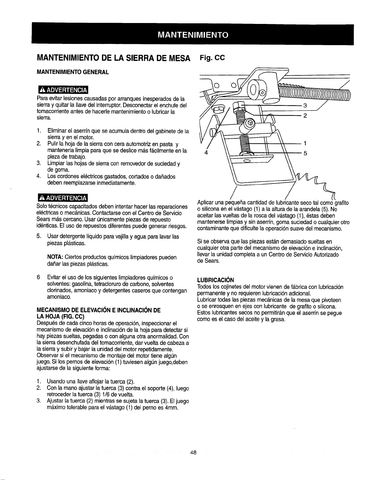
MANTENIMIENTO DE LA SIERRA DE MESA
MANTENIMIENTOGENERAL
r!V;!elVj: :i / =_[e,]!
Paraevitar lesionescausadaspor arranquesinesperadosde la
sierray quitar la Ilavedel interruptor.Desconectarel enchufedel
tomacorrienteantes de hacerle mantenimientoo lubricarla
sierra.
1. Eliminarel aserrfn que se acumuladentrodel gabinetede la
sierray en el motor.
2. Pulir la hoja de la sierraconcera automotrizen pasta y
mantenerlalimpiapara que se deslice m_tsf_.cilmenteenla
piezade trabajo.
3. Limpiarlas hojasde sierracon removedorde suciedady
de goma.
4. Loscordones electricosgastados,cortadoso daSados
deben reemplazarseinmediatamente.
!V:!elvj=;I i=_[q [
Solotecnicos capacitadosdeben intentarhacer lasreparaciones
electricaso mec_nicas.Contactarseconel Centrode Servicio
Searsm_.scercano.Usar t_nicamentepiezasde repuesto
identicas.El uso de repuestosdiferentespuede generar riesgos.
5. Usardetergente lfquidoparavajillay agua para lavarlas
piezaspl_tsticas.
NOTA:Ciertosproductosqufmicoslimpiadorespueden
daSarlas piezas pl_.sticas.
6
Evitarel usode los siguienteslimpiadoresqufmicoso
solventes:gasolina,tetraclorurode carbono,solventes
clorinados,amoniacoy detergentescaseros que contengan
amoniaco.
MECANISMO DEELEVACI(_NE INCLINACIONDE
LA HOJA(FIG.CC)
Despu_sde cadacinco horasde operaci6n, inspeccionarel
mecanismo de elevaci6ne inclinaci6nde la hoja para detectarsi
hay piezassueltas, pegadaso con algunaotra anormalidad.Con
la sierradesenchufadadel tomacorriente,dar vuelta de cabeza a
la sierray subiry bajar la unidad del motor repetidamente.
Observar si el mecanismode montaje del motortiene alg_n
juego.Si los pernosde elevaci6n(1) tuviesenalglJnjuego,deben
ajustarsede la siguienteforrna:
1. Usando una Ilaveaflojarla tuerca (2).
2. Con la manoajustar la tuerca (3) contra el soporte (4),luego
retrocederlatuerca(3) 1/6de vuelta.
3. Ajustar la tuerca (2) mientrassesujeta la tuerca (3). Eljuego
m_imo tolerableparael v_.stago(1) del perno es 4mm.
Fig. CC
0 O!
/
Aplicar una pequeSacantidadde lubricantesecotal como grafito
o siliconaen el vastago(1) a la altura de la arandela (5).No
aceitar lasvueltasde la rosca del va.stago(1), estasdeben
mantenerselimpiasy sin aserrfn,gomasuciedado cualquierotro
contaminanteque dificultela operaci6nsuavedel mecanismo.
Si se observaque las piezasest_.ndemasiadosueltasen
cualquierotra partedel mecanismode elevaci6ne inclinaci6n,
Ilevarla unidadcompletaa un Centrode Servicio Autorizado
de Sears.
LUBRICACION
Todoslos cojinetesdel motor vienende fa.bricacon lubricaci6n
permanentey no requierenlubricaci6nadicional.
Lubricartodas las piezasmecanicasde la mesa que pivoteen
o se enrosquenen ejes con lubricante de grafito o silicona.
Estoslubricantessecos no permitir_.nque el aserrfnse pegue
como es el caso del aceite y la grasa.
48
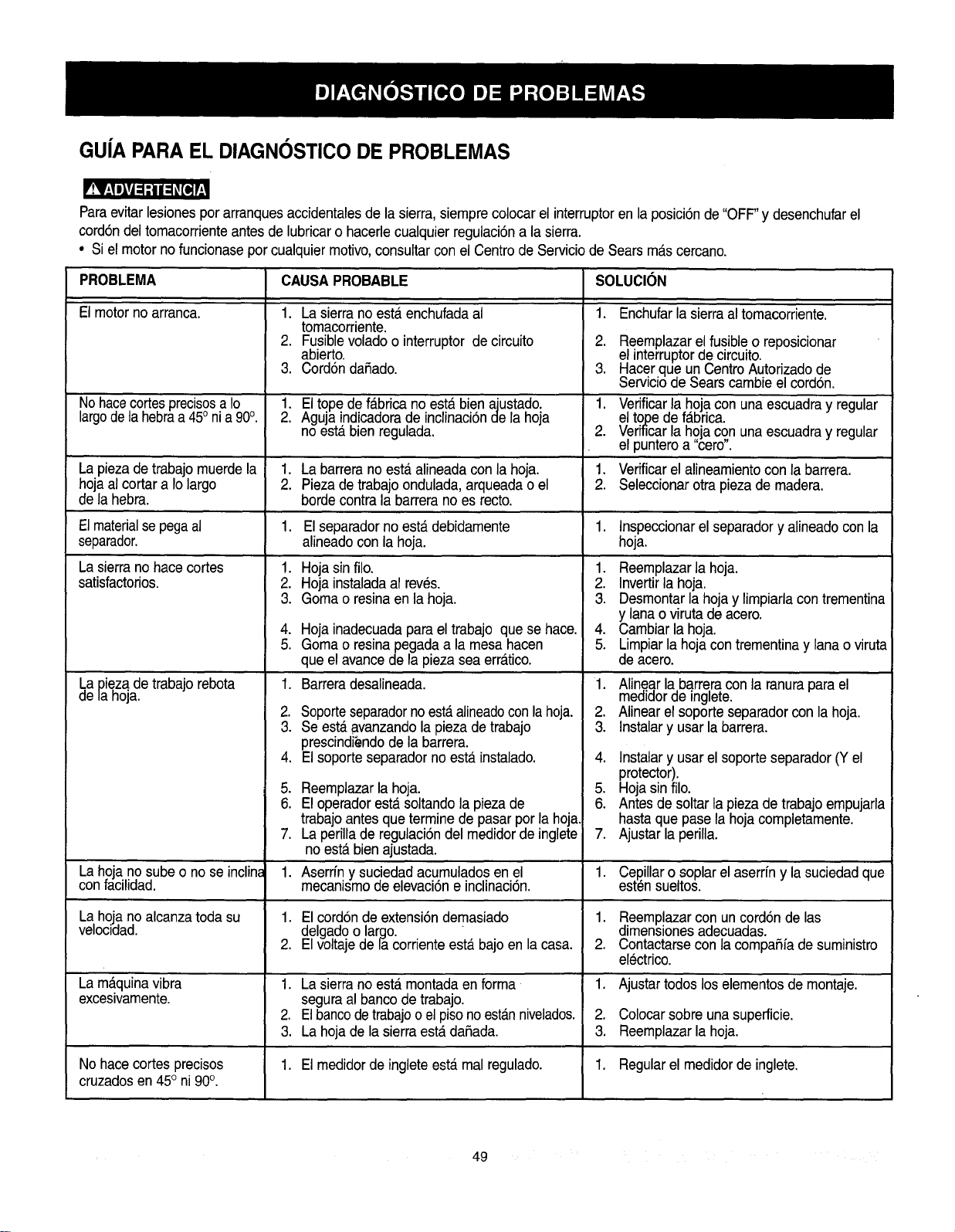
GU|A PARA EL DIAGNOSTICO DE PROBLEMAS
'!V.,II_vj:1;I I ;I_[o]!
Paraevitar lesionespor arranquesaccidentalesde la sierra, siemprecolocar el interruptoren la posici6n de "OFF"y desenchufarel
cord6ndel tomacorrienteantesde lubricaro hacerlecualquier regulaci6na la sierra.
• Si el motorno funcionasepor cualquiermotivo,consultarconel Centrode Serviciode Searsmas cercano.
PROBLEMA CAUSAPROBABLE SOLUCION
El motor no arranca. 1. La sierrano esterenchufadaal
tomacorriente.
2. Fusiblevoladoo interruptor de circuito
abierto.
3. Cord6ndafiado.
1. Enchufarla sierraal tomacorriente.
.
3.
NohacecortesprecisosaIo 1. El tope de fabrica no esta bien ajustado. 1.
largode la hebraa 45onia 90°. 2. Aguja indicadorade inclinaci6nde la hoja
no esta bien regulada. 2.
La piezade trabajomuerdela 1. La barrera no esta alineadacon la hoja. 1.
hojaal cortar a Iolargo 2. Piezade trabajoondulada,arqueada o el 2.
de la hebra, bordecontra la barrerano es recto.
1. Hojasin filo.
2. Hojainstaladaal rev@s.
3. Gomao resinaen la hoja.
Reemplazarel fusibleo reposicionar
el interruptorde circuito.
Hacerque un CentroAutorizadode
Serviciode Sears cambieel cordon.
Verificarla hojacon una escuadray regular
eltope de f_tbrica.
Verificarla hojacon unaescuadray regular
el punteroa "cero".
Verificarel alineamientocon la barrera.
Seleccionarotra piezade madera.
Elmaterialsepegaal 1. El separadorno esta debidamente 1. Inspeccionarel separadory alineadocon la
separador, alineadocon la hoja. hoja.
La sierrano hacecortes
satisfactorios.
4. Hojainadecuadapara el trabajo que se hace.
5. Gomao resinapegada a la mesa hacen
que el avancede la pieza seaerr_ttico.
1. Barreradesalineada.
2. Soporteseparadornoest&alineadoconlahoja.
3. Se est,. avanzandola piezade trabajo
prescindi_ndode la barrera.
4. El soporte separadorno esta instalado.
La Diezade trabajo rebota
de la hoja.
.
6.
Reemplazarla hoja.
El operadorest,_soltando la pieza de
trabajoantes que termine de pasarpor la hoja.
La perilla de regulaci6ndel medidorde inglete
no esta bienajustada.
Aserfin y suciedad acumuladosen el
mecanismode elevaci6ne inclinaci6n.
1. Reemplazarla hoja.
2. Invertirla hoja.
3. Desmontarla hoja y limpiarlacontrementina
y lanao viruta de acero.
4. Cambiar la hoja.
5. Limpiarla hoja contrementinay lana o viruta
de acero.
1. Alinear la barreracon la ranurapara el
medidorde inglete.
2. Alinear el soporte separadorcon la hoja.
3. Instalary usar la barrera.
4. Instalary usar el soporte separador(Y el
protector).
5. Hojasin filo.
6. Antes de soltar lapiezade trabajoempujarla
hastaque pase la hoja completamente.
7. Ajustar la perilla.
,
La hoja no subeo no se inclina 1. 1. Cep_illaro soplarelaserrfn y la suciedadque
confacilidad, est_n sueltos.
La hoja no alcanzatoda su 1. El cordonde extensi6ndemasiado 1. Reemplazarcon un cord6nde las
velocidad, delgadoo largo. " dimensionesadecuadas.
2. El voltajede la corrienteesta bajo en la casa. 2. Contactarseconla compafifa de suministro
electrico.
La m_quinavibra 1. La sierrano est,. montadaen forma 1. Ajustar todos loselementosde montaje.
excesivamente, seguraal bancode trabajo.
2. Elbancode trabajoo elpisonoestannivelados. 2. Colocarsobreunasuperficie.
3. La hoja de la sierraesterdafiada. 3. Reemplazarla hoja.
No hacecortesprecisos 1. El medidorde ingleteesta.mal regulado. 1. Regularel medidorde inglete.
cruzadosen 45° ni 90°.
49
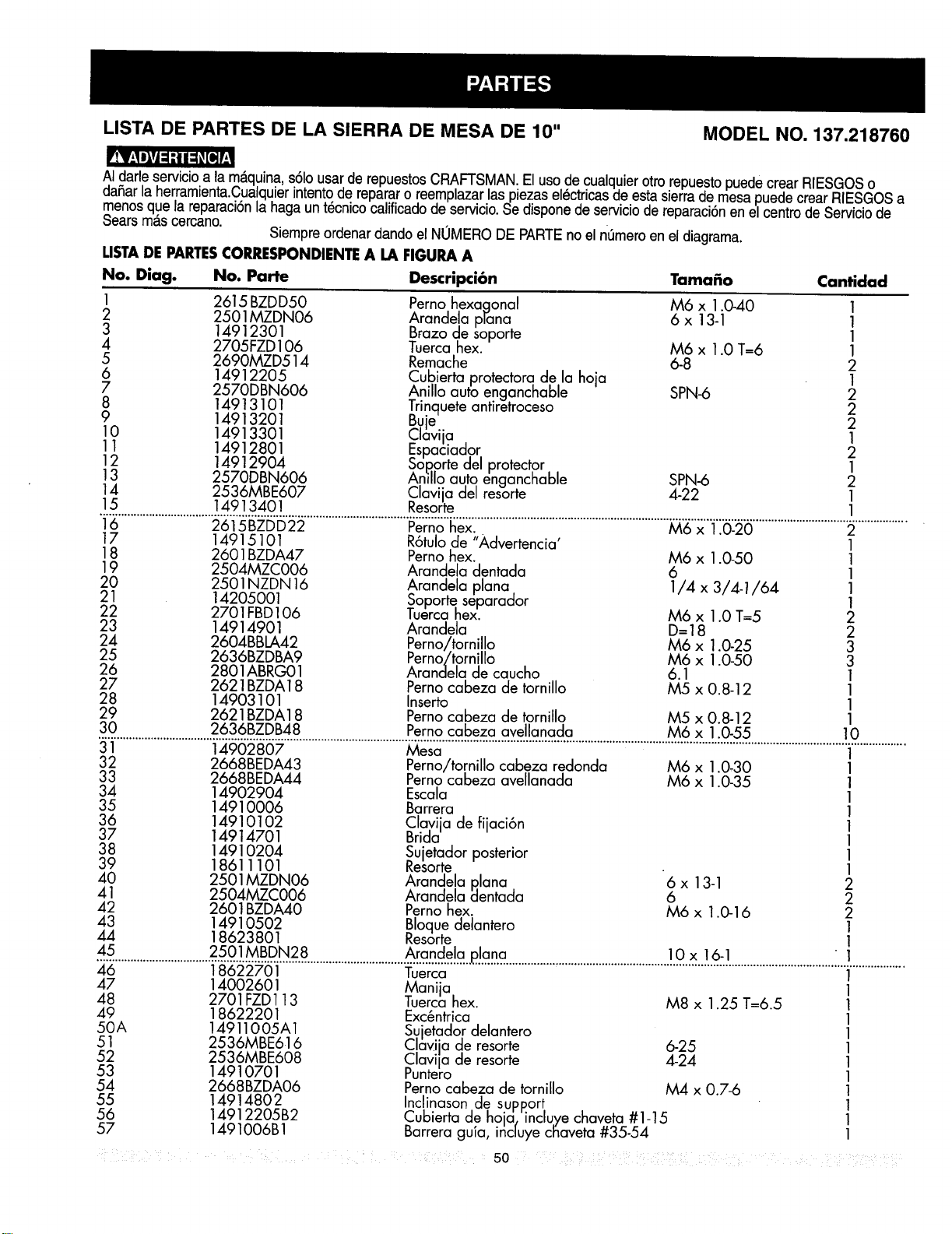
LISTA DE PARTES DE LA SIERRA DE MESA DE 10" MODEL NO. 137.218760
AIdarle servicioa la m_.quina s61ousar de repuestosCRAFTSMAN.El uso de cualquierotto repuestopuede crear RIESGOSo
dahar la herramienta.CualquierJntentode repararo reemplazarlaspiezas electricasde esta sierrade mesapuede crear RIESGOSa
menosque la reparaci6nla haga un t_cnicocalificadode servicio.Se disponede serviciode reparaci6nen el centrode Serviciode
Searsmas cercano.
Siempreordenardando el NUMERO DEPARTEno el n0meroen el diagrama.
LISTADE PARTESCORRESPONDIENTEA LA FIGURA A
No. Diag. No. Parte Descripci6n Tama_o Cantidad
1 2615 BZDD50 Perno hexa.qonal M6 x 1.0-40 1
2 2501MZDN06 Arandelo prona 6 x 13-1 1
3 14912301 Brazo de soporte 1
4 2705FZD 106 Tuerca hex. M6 x 1.0 T=6 1
5 2690MZD514 Remache 6-8 2
6 14912205 Cubierta protectora de la hoja 1
7 2570DBN606 Anillo auto enganchable SPN-6 2
8 14913101 Trinquete antiretroceso 2
9 14913201 Buje 2
10 14913301 Clavija 1
11 14912801 Espaciador 2
12 14912904 SoDorte del protector 1
13 2570DBN606 Anillo auto enganchable SPN-6 2
14 2536MBE607 Clavija del resorte 4-22 1
15 1491340 ! Resorte 1
16 2615BZDD22 Perno hex. M6 x 1.0-20 2
17 14915101 R6tulode "Advertencia' 1
18 2601BZDA47 Perno hex. M6 x 1.0-50 1
19 2504MZC006 Arandela dentada 6 1
20 2501NZDN 16 Arandela plana 1/4 x 3/4-1/64 1
21 14205001 Soporte separador 1
22 2701FBD106 Tuercahex. M6 x 1.0 T=5 2
23 14914901 Arandela D=18 2
24 2604BBLA42 Perno/tornillo M6 x 1.0-25 3
25 2636BZDBA9 Perno/tornillo M6 x 1.0-50 3
26 2801ABRG01 Aranclela de caucho 6.1 1
27 2621BZDA18 Perno cabeza de tornillo M5 x 0.8-12 1
28 14903101 Inserto 1
29 2621BZDA18 Perno cabeza de tornillo M5 x 0.8-12 1
30 2636BZDB48
Perno cabeza avellanada M6 x 1.0-55 10
31 14902807 Mesa 1
32 2668BEDA43 Perno/tornillo cabeza redonda M6 x 1.0,30 1
33 2668BEDA44 Perno cabeza avellanada M6 x 1.0-35 1
34 14902904 Escala 1
35 14910006 Barrera 1
36 14910102 Clayija de fijaci6n 1
37 14914701 Brida 1
38 14910204 Sujetador posterior 1
39 18611101 Resorte - 1
40 2501MZDN06 Arandela Rlana 6 x 13-1 2
41 2504MZC006 Aranclela _entada 6 2
42 2601BZDA40 Perno hex. M6 x 1.0-16 2
43 14910502 Bloque delantero 1
44 18623801 Resorte 1
45..............................2. .............................. .......................................................................................L.!..................
46 18622701 Tuerca 1
47 14002601 Manija 1
48 2701FZD113 Tuerca hex. M8 x 1.25 T=6.5 1
49 18622201 Exc_ntrica 1
50 A 149110 05A 1 Sujetador delantero 1
51 2536MBE616 C av a de resorte 6-25 1
52 2536MBE608 Clavija de resorte 4-24 1
53 14910701 Puntero 1
54 2668BZDA06 Perno cabeza de tornillo M4 x 0.7-6 1
55 1491480 2 Inclinason de supp.ort 1
56 14912205B2 Cubierta de hoja, incluye chaveta #1-15 1
57 1491006B 1 Barrera guia, inc|uye cl_aveta#35-54 1
: 50 .... ........
iI i
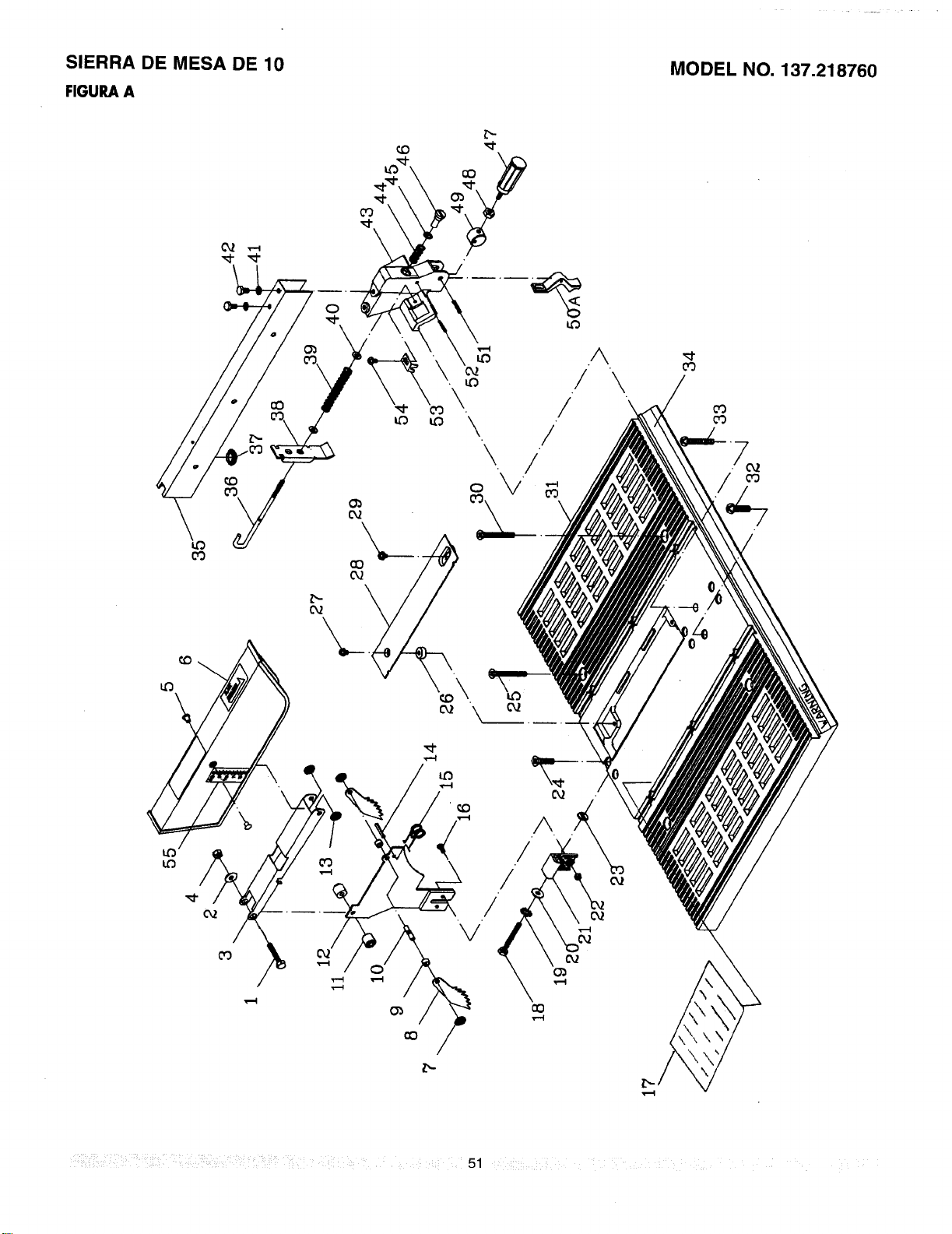
SIERRA DE MESA DE 10
FIGURAA
MODEL NO. 137.218760
cO
o3
A
/ \
! \
/
I"-
!iii31_!d_!'! ilii i i !difi ¸¸:! _;IP _!d !! k 51 :i/
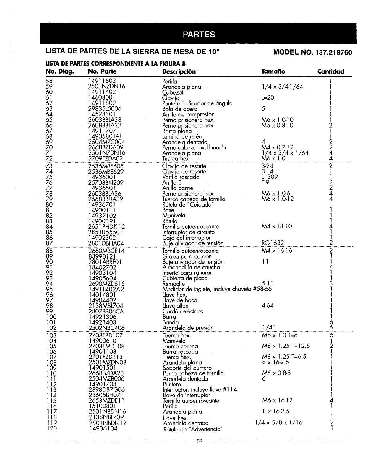
LISTA DE PARTES DE LA SIERRA DE MESA DE 10" MODEL NO. 137.218760
LISTADE PARTESCORRESPONDIENTEA LA FIGURA B
No. Diag. No. Parte Descripci6n Tama_o Cantidad
58 14911602 Perilla
59 2501NZDN 16 Arandela plana 1/4 x 3/4-1/64
60 14911402 Cabezal
61 14608001 Clavi ja L=20
62 14911802 Puntero indicador de _ngulo
63 29835L5006 Bola de acero 5
64 14523301 Anillo de compresi6n
65 2603BBLA38 Pernoprisionero hex. M6 x 1.0-10
66 2608BBLA32 Perno prisionero hex. M5 x 0.8-10
67 14911707 Barra plana
68 14905801A1 L6mina de retch
69 2504MZC004 Arandela dentada 4
70 2668BZDA09 Perno cabeza avellanada M4 x 0.7-12
71 2501NZDN 16 Arandela plana 1/4 x 3/4 x 1/64
72 2709FZDA02 Tuerca hex. M6 x 1.0
1
1
1
1
1
1
1
1
2
1
1
2
2
4
4
73 2536MBE605 Clavi a de resorte 3-24 2
74 2536MBE629 Claviia de resorte 3-14 1
75 14936001 Varilla roscada L--309 1
76 2570BBN209 Anillo E E-9 2
77 14936501 Anillo parrie • 2
78 2603BBLA36 Pernoprisionero hex. M6 x 1.0-6 4
79 2668BBDA39 Tuerca cabeza de tornillo M6 x 1.0-12 4
80 14936701 R6tulode "Cuidado" 1
81 14900111 Base 1
82 14937102 Ma nivela 1
83 149003 91 R6tulo 1
84 2651PHDK 12 Tornillo autoenroscante M4 x 18-10 4
85 2853U55501 Interru,ptorde circuito 1
86 14902302 Caja gel in!errujotor 1
.............................. ................................ .........................................................................2..................
88 2660MBCE 14 Tornillo autoenroscante M4 x 16-16 2
89 83990121 Grapa para cord6n 1
90 2801ABRF01 Bujealiviador de tensi6n 11 1
91 18402702 Alrnohadilla de caucho 4
92 14903104 _serto para ranurar 1
93 14905604 _ubierta cte placa 1
94 2690MZD515 Remache 5-11 3
95 14911402A2 Medidor de inglete, incluye chaveta #58-66 1
96 14014801 Llave hex. 1
97 14904402 Llavede boca 1
98 2138MBL704 Llave allen 4-64 1
99 2807BB06CA Cord6n el_ctrico 1
1O0 14921306 Barra 1
101 14921403 Banda 6
.!.0..2............................ ................................ ...........................................1.../..4.11................................................6..................
103 2708FBD107 Tuerca hex. M6 x 1.0 T=6 6
104 14900610 Manivela 1
105 2703FMD108 Tue_cacorona M8 x 1.25 T=I 2.5 2
106 14901103 Barra roscada 1
107 2701FZD113 Tuerca hex. M8 x 1.25 T=6.5 1
108 2501MZDN08 Arandela p,lana 8 x 16-2.5 1
109 14901501 Soporte del puntero 1
110 2668BZDA23 Perno cabeza de tornillo M5 x 0.8-8 1
111 2504MZBO06 Arandela dentada 6 1
112 14901703 Puntero 1
113 2898DB7G06 Interru,ptor,incluye Ilave #114 1
114 28605BH071 Llavede interruptor 1
115 2653MZDE11 Tornillo autoenroscante M6 x 16-12 4
116 15100801 Perilla 1
117 2501NBDN 16 Arandela plana 8 x 16-2.5 1
118 2138NBL709 Llave hex. 1
119 2501NBDN12 Arandela dentada 1/4 x 5/8 x 1/16 2
120 14906104 R6tulode "Advertencia' 1
52
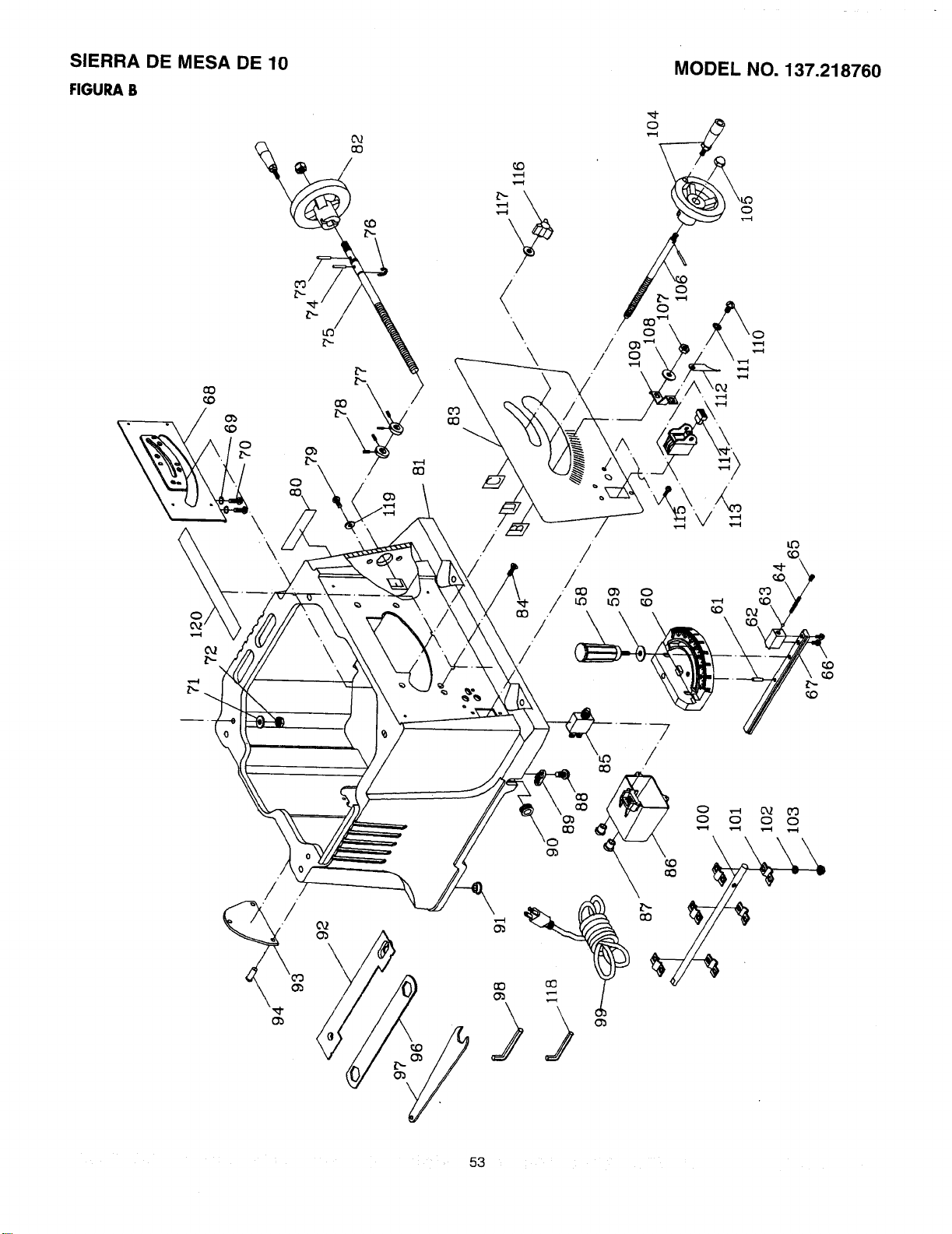
SIERRA DE MESA DE 10
FIGURA B
cD
\
/
/
/
MODEL NO. 137.218760
co
¢,0
o o o o
cO
53
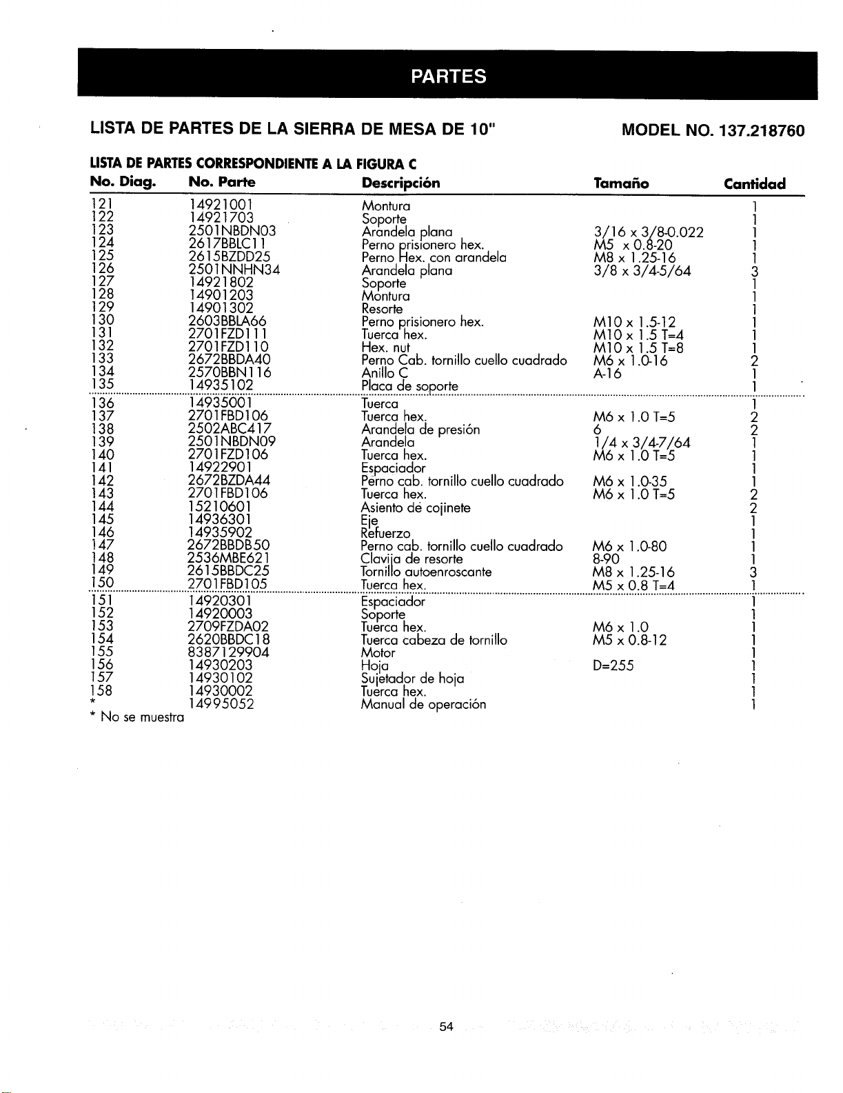
LISTA DE PARTES DE LA SIERRA DE MESA DE 10"
MODEL NO. 137.218760
LISTADE PARTESCORRESPONDIENTEA LA FIGURA C
No. Diag. No. Parte Descripci6n
121 14921001 Montura
122 14921703 Soporte
123 2501NBDN03 Arandela plana
124 2617BBLC 11 Perno prislonero hex.
125 2615BZDD25 Perno Hex. con arandela
126 2501NNHN34 Arandela plana
127 14921802 Soporte
128 14901203 Montura
129 14901302 Resorte
130 2603BBLA66 Perno p.risionero hex.
131 2701FZD111 Tuercahex.
132 2701FZD110 Hex. nut
133 2672BBDA40 Perno Cab. tornillo cuello cuadrado
134 2570BBN 116 Anillo C
TamaEo Cantidad
/516 x 3/8-0.022
x 0.8-20
M8 x 1.25-16
3/8 x 3/4-5/64
M10x 1.5-12
M10 x 1.5 T--4
M10 x 1.5 T=8
M6 x 1.0-16
A-16
1
1
1
1
1
3
1
1
1
1
1
1
2
1
135 14935102 Placa de soporte 1 "
136 14935001 Tuerca
137 2701FBD106 Tuerca hex.
138 2502ABC417 Arandela de presi6n
139 2501NBDN09 Arandela
140 2701 FZD106 Tuerca hex.
141 14922901 Espaciador
142 2672BZDA44 Perno cab. tornillo cuello cuadrado
143 2701FBD106 Tuerca hex.
144 15210601 Asiento de cojinete
145 14936301 Eje
146 14935902 Refuerzo
147 2672BBDB50 Perno cab. tornillo cuello cuadrado
148 2536MBE621 Clavi a de resorte
149 2615BBDC25 Torni o autoenroscante
M6 x 1.0 T=5
6
1/4 x 3/4-7/64
M6 x 1.0 T=5
M6 x 1.0-35
M6 x 1.0 T=5
M6 x 1.0-80
8-90
M8 x 1.25-16
1
2
2
1
1
1
1
2
2
1
1
1
1
3
150 2701FBD105 Tuerca hex. M5 x 0.8 T=4 1
.............................................................................................................................................................................................i..................
152 14920003 Soporte 1
153 2709FZDA02 Tuerca hex. M6 x 1.0 1
154 2620BBDC18 Tuerca cabeza de tornillo M5 x 0.8-12
155 8387129904 Motor
156 14930203 Hoja D=255
157 14930102 Sujetador de hoja
158 14930002 Tuerca hex.
* 14995052 Manual de operaci6n
* No se muestra
1
1
1
1
1
1
54
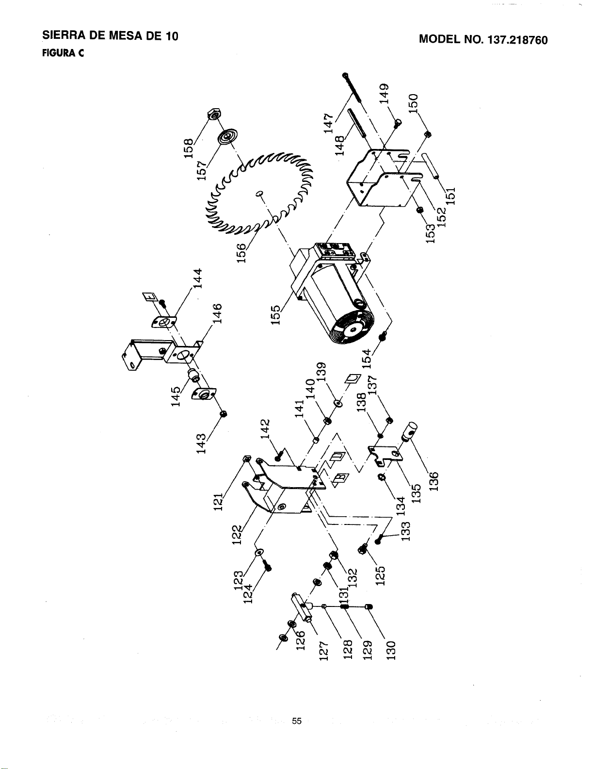
SIERRA DE MESA DE 10
FIGURA C
MODEL NO, 137.218760
\
55
I_ WARNING
Some dust created by power sanding, sawing, grinding, drilling and other construction activities contains
chemicals known to cause cancer, birth defects or other reproductive harm. Some examples of these
chemicals are:
o Lead from lead-based paints
o Crystalline silica from bricks, cement and other masonry products
• Arsenic and chromium from chemically treated lumber
Your risk from these exposures varies, depending on how often you do this type of work. To reduce your
exposure to these chemicals, work in a well ventilated area and work with approved safety equipment such as
dust masks that are specially designed to filter out microscopic particles.
[_1_ ADVERTENCiA J
El poivo originado por el uso de lijadoras, sierras, moiedoras, taladros y por algunas actividades relacionadas
con la construcci6n contiene qufmicos reconocidos como causantes de c_ncer, malformaciones cong_nitas
u otros da_os reproductivos. Algunos ejemplos de estos qufmicos son:
• Piomo de las pinturas a base de plomo
S{lice cristalina proveniente de los ladrilios, del cemento y de otros productos de alba_iler{a
• Ars_nico y el cromo proveniente de las maderas tratadas con qu{micos
El riesgo que implican estas exposiciones varfa seg_n la frecuencia con que se realice este tipo de trabajo.
Para reducir la exposici6n a estos qu_micos, trabaje en un _rea bien ventilada y utilice un equipo de seguridad
aprobado, como m_scaras contra polvo especialmente dise_adas para filtrar part_culas microsc6picas.

For in-home major brand repair service:
Call 24 hours a day, 7 days a week
1-800-4-M Y-H 0 ME°°(1-800-469-4663)
Para pedir servicio de reparaci6n a domicilio - 1-800-676-5811
In Canada for all your service and parts needs call
- 1-800-665-4455
Au Canada pour tout le service ou les pi_ces
For the repair or replacement parts you need"
Call 6 a.m. - 11 p.m. CST, 7 days a week
PartsDirect
1-800-366-PART (1-800-366-7278)
Para ordenar piezas con entrega a domicilio - 1-800-659-7084
For the location of a Sears Service Center in your area:
Call 24 hours a day, 7 days a week
1-800-488-1222
To purchase or inquire about a Sears Maintenance Agreement:
Call 7 a.m.- 5 p.m. CST, Monday - Saturday
1-800-827-6655
p-- •
SEARS
HomeCentral
8/99