Loading ...
Loading ...
Loading ...
1. Make certain your dryer is equipped for use with the type of
gas in your laundry room. Dryer is equipped at the factory for
Natural Gas with a 3/8 inch NPT gas connection.
NOTE: The gas service to a gas dryer must conform
with the local codes and ordinances, or in the ab-
sence of local codes and ordinances, with the latest
edition of the National Fuel Gas Code ANSI Z223.1/
NFPA 54 or the CAN/CSA-B149.1 Natural Gas and
Propane Installation Code.
Natural Gas, 1000 Btu/ft
3
[37.3 MJ/m
3
], service must be supplied
at minimum 5.0 inch water column pressure to maximum 10.5
inch water column pressure.
For proper operation at altitudes above 3000 feet [915 m] the nat-
ural gas valve spud orifice size must be reduced to ensure com-
plete combustion. Refer to Table 3 .
Natural Gas Altitude Adjustments
Altitude Orifice Size
Part
No.feet [m] No. inches [mm]
3000 [915] 43 0.0890 [2.26] D503778
6000 [1830] 44 0.0860 [2.18] 58719
8000 [2440] 45 0.0820 [2.08] D503779
9000 [2740] 46 0.0810 [2.06] D503780
10,000 [3050] 47 0.0785 [1.99] D503781
Table 3
2. Remove the shipping cap from the gas connection at the rear
of the dryer. Make sure you do not damage the pipe threads
when removing the cap.
NOTE: If gas supply connection is British Standard
Pipe Tapered thread (BSPT), order 44178804 brass
female NPT (FPT) to male BSPT gas pipe thread
adapter, available at extra cost.
3. Connect to gas supply pipe using thread sealant or Teflon
tape. Torque 90 - 175 inch-pounds [10.2 - 19.7 Nm].
NOTE: The connection of gas supply to the appli-
ance shall be made with a flexible hose suitable for
the appliance category in accordance with national
installation regulations of the country of destina-
tion. If in doubt contact the dryer distributor or man-
ufacturer.
NOTE: When connecting to a gas line, an equipment
shut-off valve in accordance with the National Fuel
Gas Code, ANSI Z223.1/NFPA 54 and the Natural
Gas and Propane Installation Code, CSA B149.1
must be installed within 6 feet [1.8 m] of the dryer.
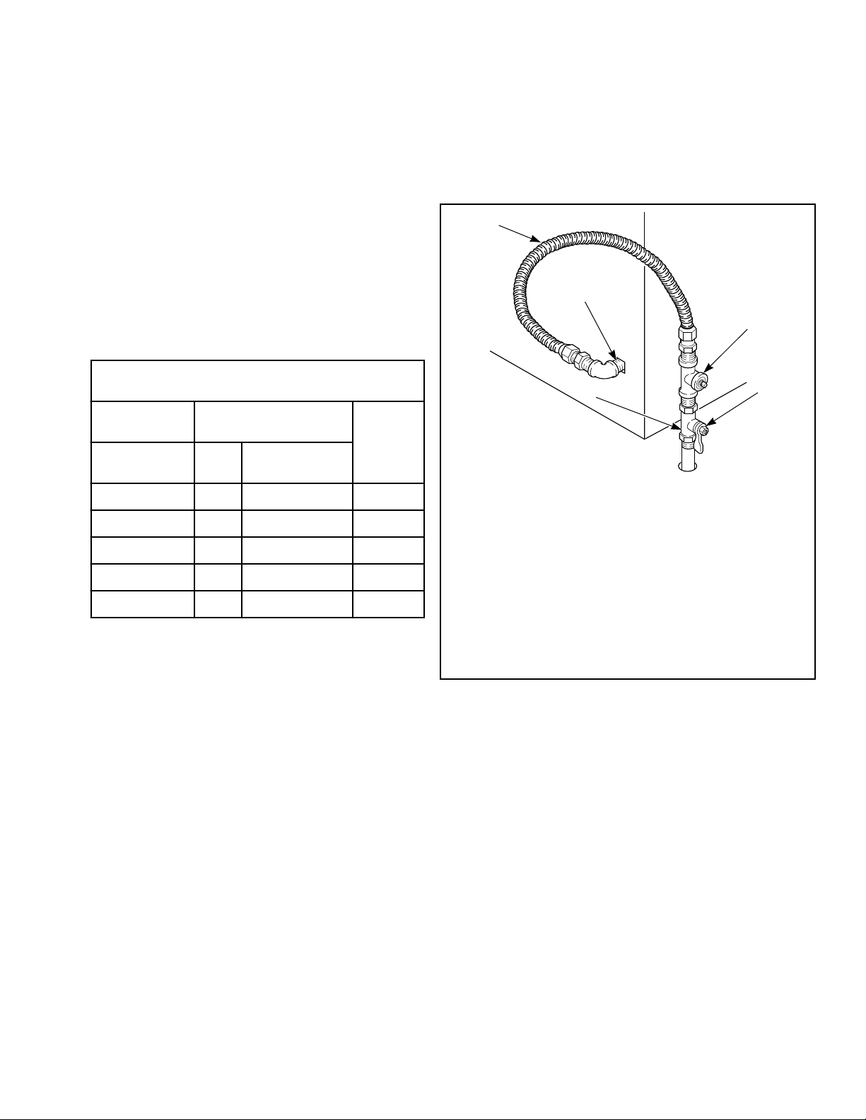
An 1/8 in. NPT pipe plug must be installed as shown
for checking inlet pressure. Refer to Figure 5 .
D233I_SVG
2
3
4
1
5
1. New Stainless Steel Flexible Connector – (Use design
CSA certified connector) Use only if allowed by local co-
des
2. 1/8 in. NPT Pipe Plug
3. Equipment Shut-Off Valve
4. Black Iron Pipe:
Shorter than 20 ft. [6.1 m] – Use 3/8 in. [9.5 mm] pipe.
Longer than 20 ft. [6.1 m] – Use 1/2 in. [12.7 mm] pipe.
5. 3/8 in. NPT Gas Connection
Figure 5
4. Tighten all connections securely but don't overtighten to avoid
breaking or bending the gas valve bracket. Turn on gas and
check all pipe connections (internal & external) for gas leaks
with a non-corrosive leak detection fluid.
NOTE: The dryer and its appliance main gas valve must
be disconnected from the gas supply piping system
during any pressure testing of that system at test pres-
sures in excess of 1/2 psi [3.45 kPa]. Refer to Check
Heat Source.
NOTE: DO NOT connect the dryer to L.P. Gas Service
without converting the gas valve. Install L.P. Gas Con-
version Kit 649P3, available at extra cost.
L.P. (Liquefied Petroleum) Gas, 2500 Btu/ft.
3
[93.1 MJ/m
3
], serv-
ice must be supplied at 10 ± 1.5 inch water column pressure.
Installation
©
Copyright, Alliance Laundry Systems LLC -
DO NOT COPY or TRANSMIT
14 Part No. D516901EN
Loading ...
Loading ...
Loading ...