
Installation
GUIDE
THERMADOR.COM
Thermador Masterpiece® Chimney Wall Hoods
DC30MTW DC36MTW DC48MTW

Table of
CONTENTS
Table of Contents
Installation instructions
9 Safety Definitions .................................................. 3
IMPORTANT SAFETY INSTRUCTIONS ........................ 4
GROUNDING INSTRUCTIONS ....................................... 4
Safety Codes and Standards ........................................... 5
Proper Installation and Maintenance .............................. 5
Proposition 65 Warning .................................................. 5
Before you begin ........................................................ 6
Parts Included ................................................................. 6
Installation Procedure ................................................. 6
Telescopic duct cover installation ................................... 6
.
9 Safety Definitions
Safety Defi nitions
9 WARNING
This indicates that death or serious injuries may
occur as a result of non-observance of this warning.
9 CAUTION
This indicates that minor or moderate injuries may
occur as a result of non-observance of this warning.
NOTICE: This indicates that damage to the appliance or
property may occur as a result of non-compliance with
this advisory.
Note: This alerts you to important information and/or
tips.
9 IMPORTANT SAFETY INSTRUCTIONS
READ AND SAVE THESE INSTRUCTIONS
4
IMPORTANT SAFET Y I NS T RUCT I ONSRE AD AND SAVE THESE INSTRUCTIONS
INSTALLER: Save these instructions for the local
electrical inspector’s use. Please leave these instructions
with this unit for the owner. Show the owner the location
of the circuit breaker or fuse. Mark it for easy reference.
OWNER: Please retain these instructions for future
reference.
WARNING
If the information in this manual is not followed exactly,
fire or shock may result causing property damage or
personal injury.
WARNING
WARNING
Turn off power circuit at service panel and lock out panel
before wiring this appliance. Requirement: 120 VAC, 60
Hz 15 A. Allow the appliance to cool after the power has
been turned off before servicing the appliance.
WARNING
AUTOMATICALLY OPERATED DEVICE
To reduce the risk of injury disconnect from power
supply before servicing.
WARNING
TO REDUCE THE RISK OF FIRE, ELECTRIC SHOCK, OR
INJURY TO PERSONS, OBSERVE THE FOLLOWING:
▯ Use this unit only in the manner intended by the
manufacturer. If you have questions, contact the
manufacturer.
▯ Before servicing or cleaning unit, switch power off at
service panel and lock the service disconnecting
means to prevent power from being switched on
accidentally.
When the service disconnecting means cannot be
locked, securely fasten a prominent warning device,
such as a tag, to the service panel.
WARNING
Do not repair, replace or remove any part of the
appliance unless specifically recommended in the
manuals. Improper installation, service or maintenance
can cause injury or property damage. Refer to this
manual for guidance. All other servicing should be done
by an authorized service provider.
WARNING
ELECTRICAL SHOCK HAZARD
GROUNDING INSTRUCTIONS
WARNING
Improper grounding can result in a risk of electric shock.
This appliance must be grounded. Grounding reduces
the risk of electric shock by providing a safe pathway for
electric current in the event of a short circuit.
Be sure your appliance is properly installed and
grounded by a qualified technician. Installation, electrical
connections and grounding must comply with all
applicable codes.
If required by the National Electrical Code (or Canadian
Electrical Code), this appliance must be installed on a
separate branch circuit.
WARNING
WARNING: To reduce the risk of fire or electric shock, do
not use this fan with any solid-state speed control device.
If the information in this manual is not
followed exactly, fire or shock may result
causing property damage, personal injury or
death.
- DO NOT store or use gasoline or other flammable
vapors and liquids in the vicinity of this or any other
appliance.
- WHAT TO DO IF YOU SMELL GAS
DO NOT try to light any appliance.
DO NOT touch any electrical switch.
DO NOT use any phone in your building.
Immediately call your gas supplier from a neighbor’s
phone. Follow the gas supplier’s instructions.
If you cannot reach your gas supplier, call the fire
department.
- Installation and service must be performed by an
authorized service provider, service agency or the gas
supplier.
DO NOT remove connections.
DO NOT use an extension cord.
Failure to follow these instructions can result in
death, fire, or electrical shock.
5
9 IMPORTANT SAFETY INSTRUCTIONS
READ AND SAVE THESE INSTRUCTIONS
Safety Codes and Standards
This appliance complies with the latest version of one or
more of the following standards:
▯ UL 507 - Electric Fans
▯ CAN/CSA C22.2 No. 113 - Fans and Ventilators
It is the responsibility of the owner and the installer to
determine if additional requirements and/or standards
apply to specific installations.
Proper Installation and Maintenance
CAUTION
Never modify or alter the construction of the appliance.
For example, do not remove leveling legs, panels, wire
covers or anti-tip brackets/screws.
CAUTION
For general ventilating use only. Do not use to exhaust
hazardous or explosive materials and vapors.
WARNING
To reduce the risk of fire, use only metal ductwork.
Use a qualified installer.
Remove all tape and packaging before using the
appliance. Destroy the packaging after unpacking the
appliance. Never allow children to play with packaging
material.
WARNING
WARNING – TO REDUCE THE RISK OF FIRE, ELECTRIC
SHOCK, OR INJURY TO PERSONS, OBSERVE THE
FOLLOWING:
▯ Installation work and electrical wiring must be done by
qualified person(s) in accordance with all applicable
codes and standards, including fire-rated construction.
▯ Sufficient air is needed for proper combustion and
exhausting of gases through the flue (chimney) of fuel
burning equipment to prevent back drafting. Follow the
heating equipment manufacturer’s guideline and safety
standards such as those published by the National Fire
Protection Association (NFPA), and the American
Society for Heating, Refrigeration and Air Conditioning
Engineers (ASHRAE), and the local code authorities.
▯ When cutting or drilling into wall or ceiling, do not
damage electrical wiring and other hidden utilities.
▯ Ducted fans must always be vented to the outdoors.
WARNING
TO REDUCE THE RISK OF A RANGE TOP GREASE
FIRE:
a.
Never leave surface units unattended at high settings.
Boilovers cause smoking and greasy spillovers that
may ignite. Heat oils slowly on low or medium settings.
b.
Always turn hood ON when cooking at high heat.
c.
Clean ventilating fans frequently. Grease should not be
allowed to accumulate on fan or filter.
d.
Use proper pan size. Always use cookware
appropriate for the size of the surface element.
Do not flambé under the extractor hood or work with a
naked flame. When switched on, the extractor hood
draws flames into the filter. There is a risk of fire due to
deposits on the grease filter!
WARNING
TO REDUCE THE RISK OF INJURY TO PERSONS IN
THE EVENT OF A RANGE TOP GREASE FIRE,
OBSERVE THE FOLLOWING:
▯ SMOTHER FLAMES with a close-fitting lid, cookie
sheet, or metal tray, then turn off the burner. BE
CAREFUL TO PREVENT BURNS. If the flames do not
go out immediately, EVACUATE AND CALL THE FIRE
DEPARTMENT.
▯ NEVER PICK UP A FLAMING PAN – You may be
burned.
▯ DO NOT USE WATER, including wet dishcloths or
towels – a violent steam explosion will result.
▯ Use an extinguisher ONLY if:
- You know you have a Class ABC extinguisher, and
you already know how to operate it.
- The fire is small and contained in the area where it
started.
- The fire department is being called.
- You can fight the fire with your back to an exit.
Proposition 65 Warning:
This product may contain a chemical known to the State
of California, which can cause cancer or reproductive
harm. Therefore, the packaging of your product may
bear the following label as required by California:
▯ Unit is heavy and requires at least two people
or proper equipment to move and install.
▯ Hidden surfaces may have sharp edges. Use
caution when handling the appliance. Failure to
do so may result in property damage or
personal injury.
&DQFHUDQG5HSURGXFWLYH+DUPZZZ3:DUQLQJVFDJRY
67$7(2)&$/,)251,$352326,7,21:$51,1*
:$51,1*
6
Before you begin
Before you begin
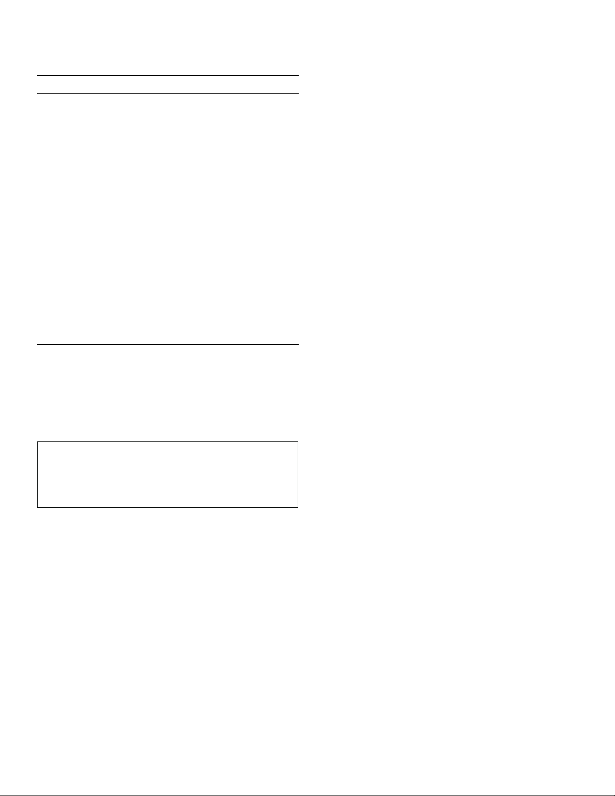
On some models, optional duct covers and telescoping
extensions may be used to fill the space between the
hood and ceiling in wall mount installations.
Parts Included
▯ Harware bag (1):
▯ 5 x 45 mm installation screws (4)
▯ 5.4 x 75 mm installation screws (4)
▯ 4.2 x 8 mm installation screws (11)
▯ 10 x 60 mm drywall anchors (4)
▯ 8 x 40 mm anchors (4)
▯ Torx adapter 20
▯ Upper duct cover brackets (2)
▯ Mounting template (1)
Installation Procedure
Installation Procedure
Telescopic duct cover installation
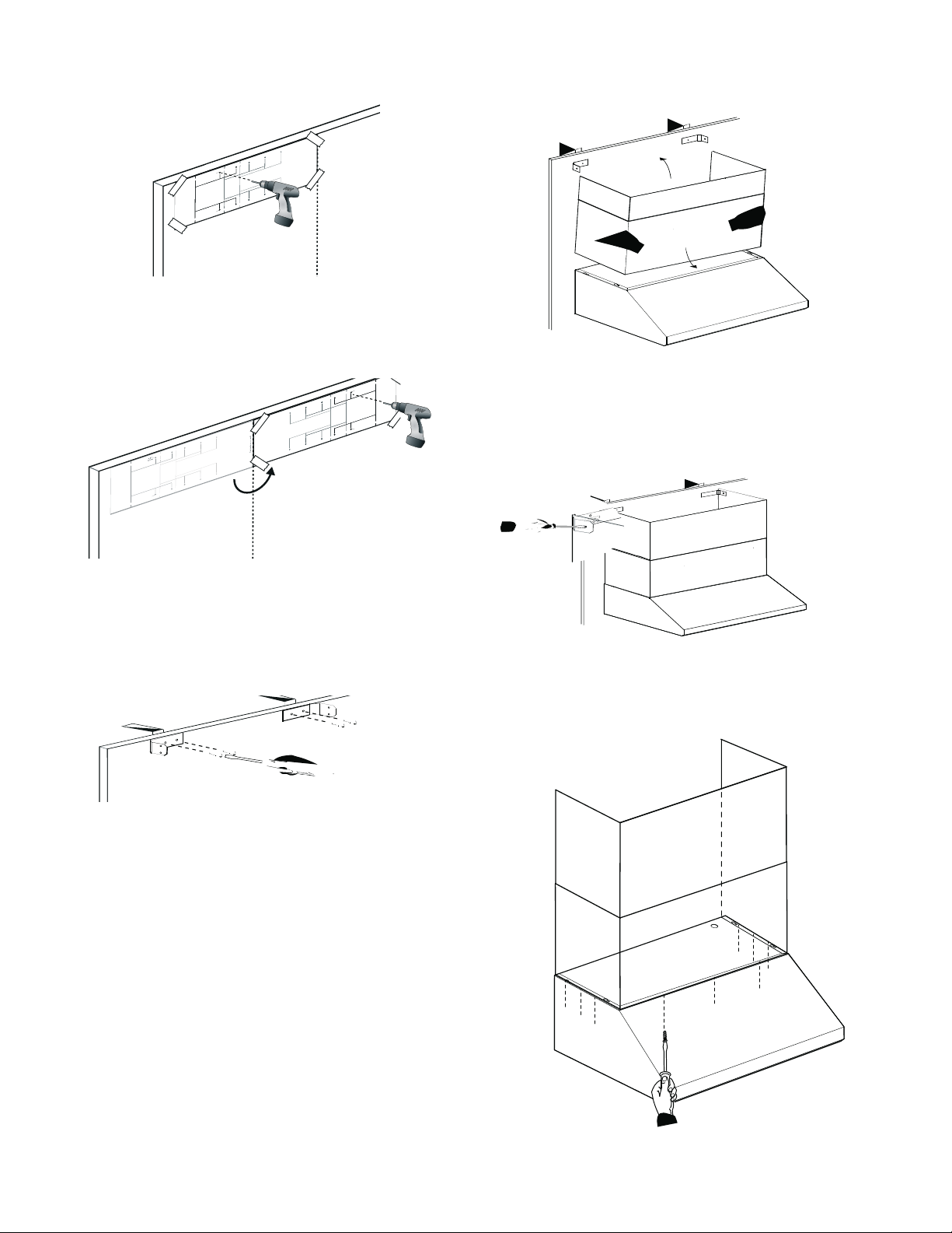
IMPORTANT: Secure the hood to the wall after installing
the duct cover mounting bracket, but before installing the
telescoping duct cover extension.
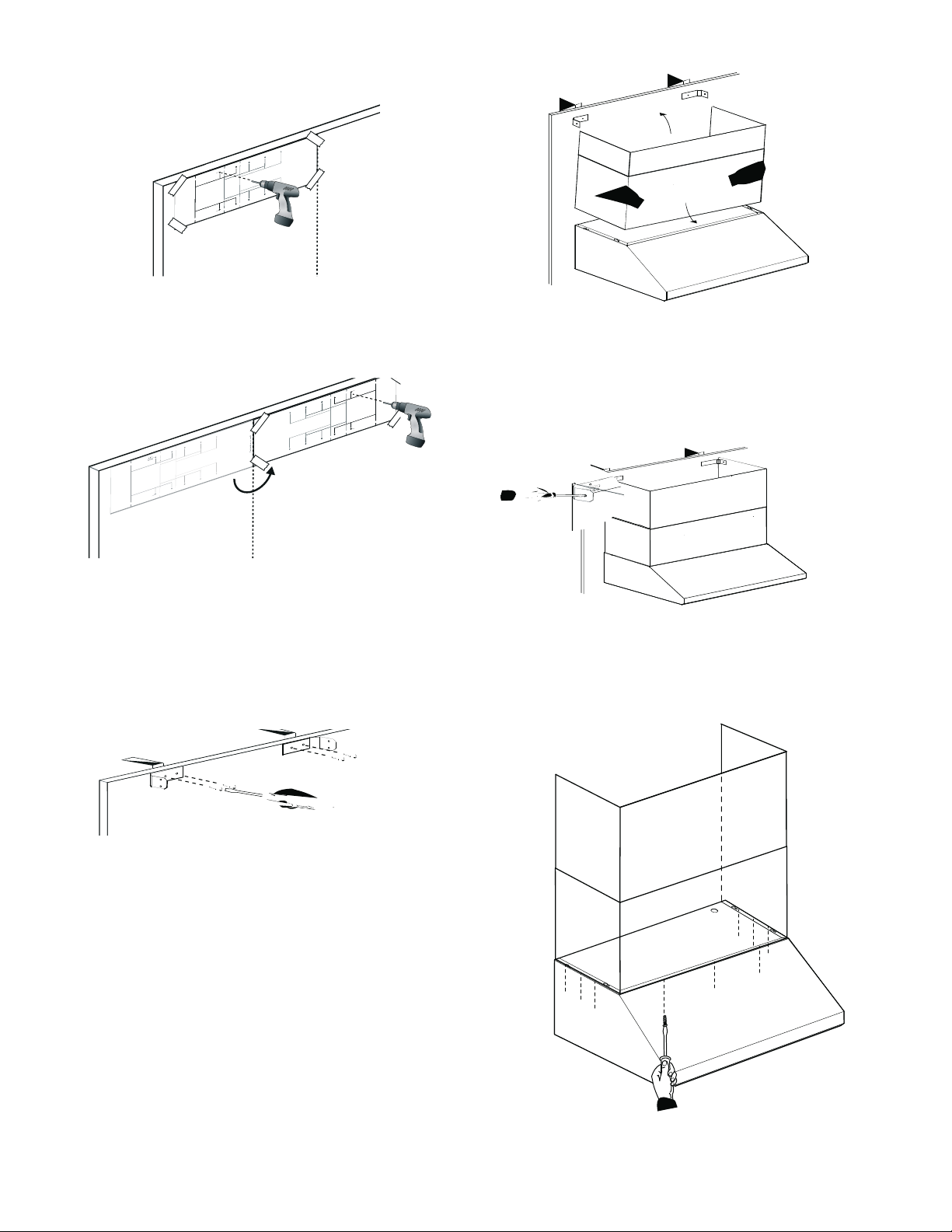
Securing the telescoping chimney extension bracket
1.
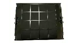
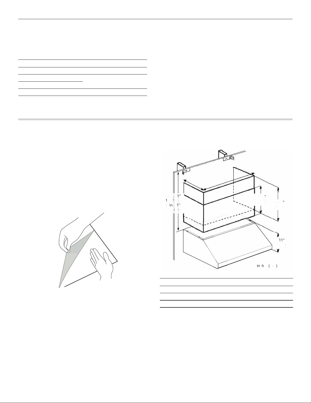
Carefully remove the protective film from the duct
cover and hood assembly prior to the start of the
installa-tion. Use one hand to maintain the duct cover
steady while the other hand removes the protective
film.
2.
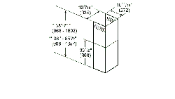
Ensure that the minimum height of 30" (762 mm) from
the bottom of the hood to the cooking surface will be
maintained.
3.
Locate two studs at the mounting brackets location.
4.
Mark the range hood vertical centerline. Make sure the
line run through the very top of the ceiling.
5.
Locate the mounting template in an 90° angle against
the recently made centerline.
Model Duct Cover
HMWB30WS DC30MTW
HMWB361WS DC36MTW
HMWB36WS
HMWB481WS DC48MTW
Model A B
30" (762 mm) 11 3⁄4" (298 mm) 29 3⁄4" (756 mm)
36" (914 mm) 11 3⁄4" (298 mm) 35 3⁄4" (908 mm)
48" (1219 mm) 11 3⁄4" (298 mm) 48" (1219 mm)
w
NN
LQFKHVPP
"
#
.BYw
NN
.JOw
NN
w
NN
w
NN
w
N
N
L
Q
F
K
H
V
P
P
"
#
.
B
Y
w
N
N
.
J
O
w
N
N
N
N
w
N
N
N
w
NN
7
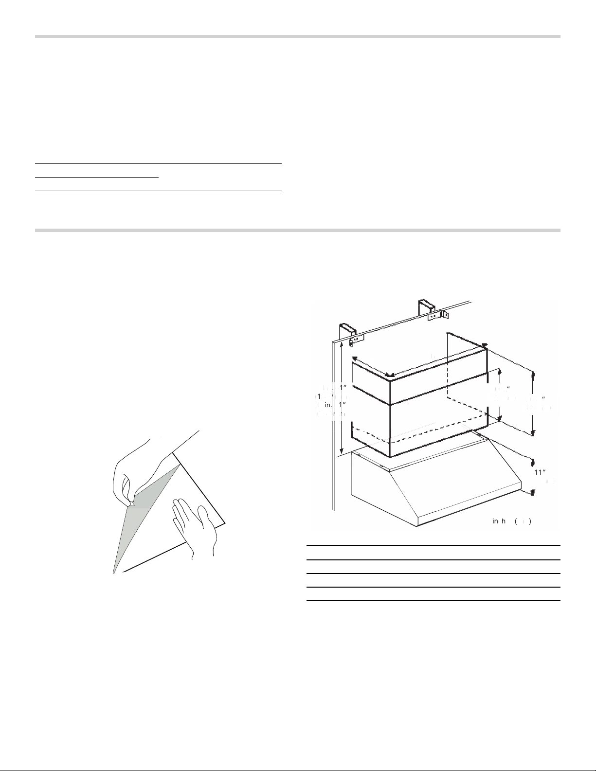
6.
Make the pilot holes depending on your duct cover
width.
7.
Gently dettach the mounting template and turn it 180°.
Locate the template against the centerline to make the
other pilot holes. Install the wall anchors depending on
the wall material (wood or plywood).
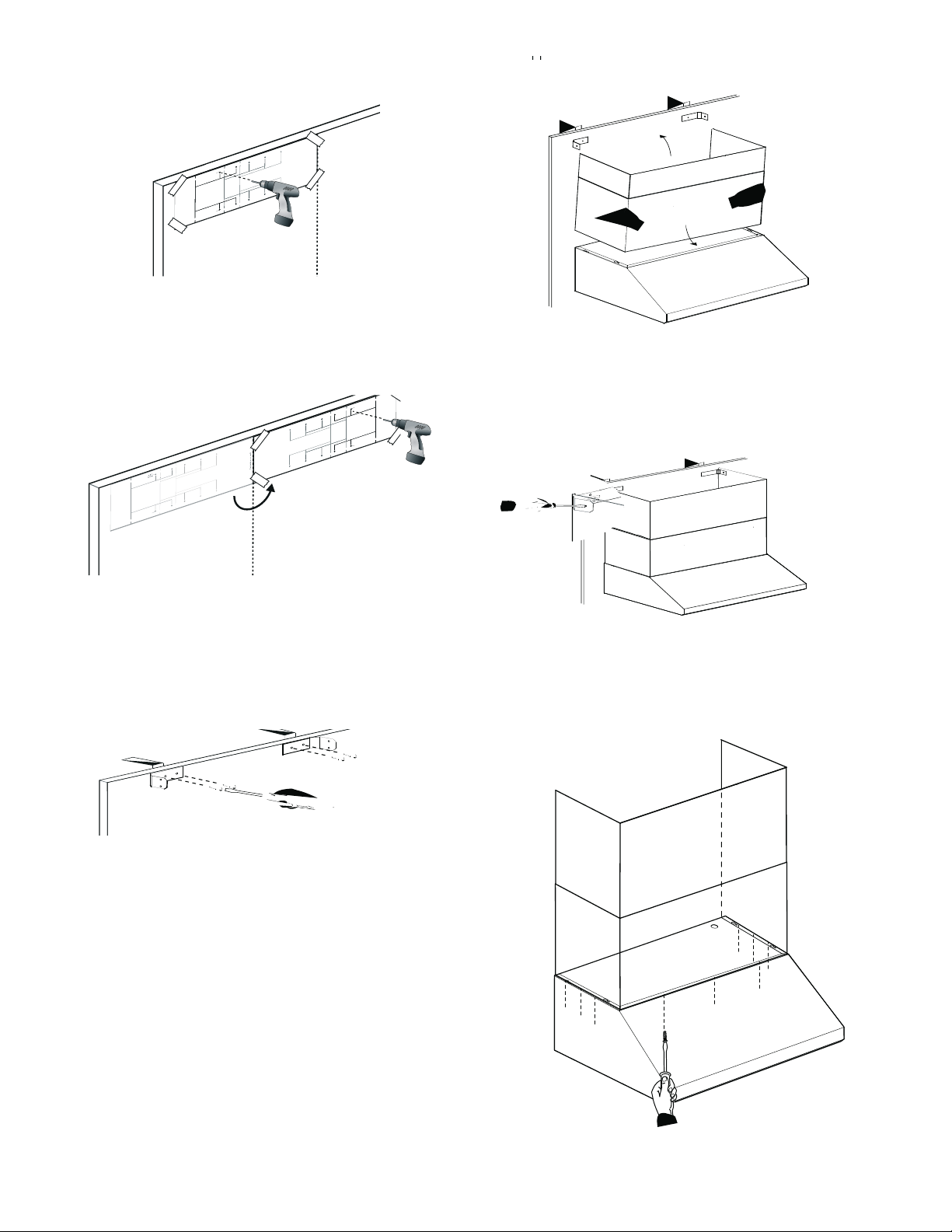
8.
Mount the duct cover bracket on the top of the ceiling
using four 5 x 45 mm screws (wood) or four 5.4 x
75 mm (plywood). Ensure that the bracket is leveled.
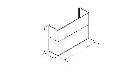
9.
Insert the complete duct cover at an angle and swivel
toward the wall.
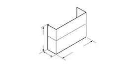
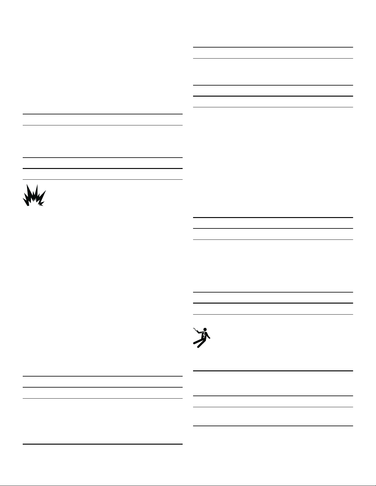
10.
Carefully pull the top part of the extension upwards.
Screw the left and right sides of the extension to the
mounting bracket with the supplied installation screws.
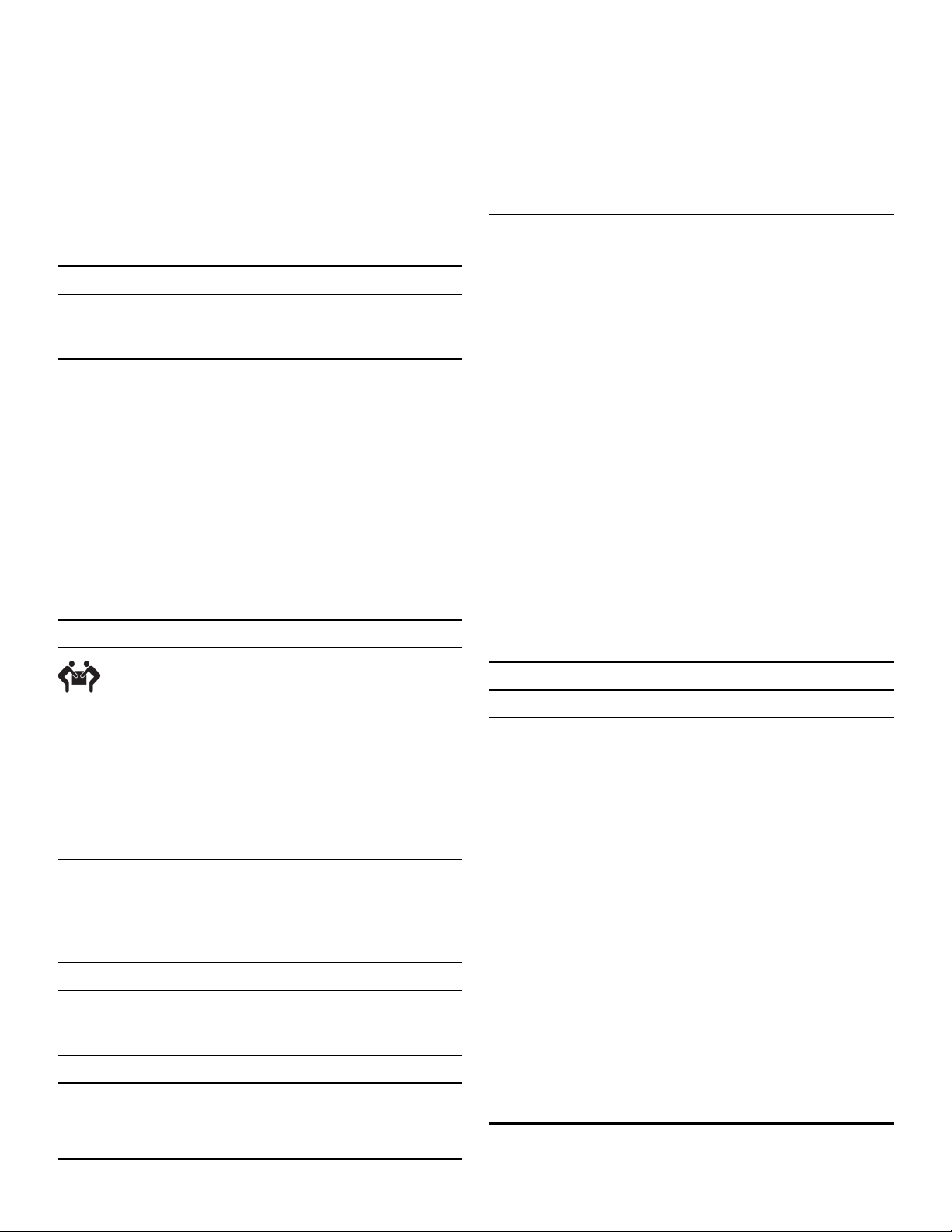
11.
From inside of hood, screw the supplied 4.2 x 8 mm
sheet metal screws through the holes on each side
and along the front into bottom of the extension.
&
HQW
HUOLQ
H
5RRI
&HQ
W
H
UO
L
Q
H
R
Q
Z
D
O
O
'
,
0
5RRI
5RRI
P
P
P
P
´
'
X
FW
F
R
Y
H
U
/H
I
W
HG
JH
´
'X
F
W
FR
YHU
,
Q
VW
DOOD
W
LR
Q
K
R
O
H
V
´
'X
F
W
FRYHU
,Q
V
WDOODWLRQKR
O
HV
´
'X
FW
FRY
H
U
,QV
W
D
O
O
DWL
RQ
K
RO
HV
´
'X
F
W
FR
YH
U
/H
I
W
H
G
JH
´
'XF
WFRYH
U
/H
I
W
H
G
J
H
P
P
´
'
X
FW
F
R
Y
H
U
5
LJ
K
W
HG
J
H
´
'XF
W
F
R
YH
U
5
L
J
K
W
H
G
J
H
´
'
X
FW
FRYH
U
5LJ K
W
H
G
J
H
´
'XFWF
RYH
U
,
Q
VW
D
OO
D
W
LRQ
K
R
O
H
V
´
'
X
FW
F
R
Y
HU
,
Q
V
WDOOD
W
LRQKR
O
HV
´
'X
FWFR
YHU
,
Q
VW
DOODWLRQ
K
R
OH
V
&
HQWHUO
LQH
5R R I
'
,
0
5RRI
5RRI
PP
PP
´
'XFWFRYHU
/HIW HG
JH
´
'X
FWFRYHU
,
Q
VWDO ODWLR
Q
KRO
H
V
V
´
'
XF
W
FRYHU
,Q
VWDO ODWLR
Q
KR
OH
V
´
'
X
FWFRYH
U
,
Q
V
W
DOO
DWLRQ
KR
OHV
´
'X
FWFR
YH
U
/HIW H
GJH
´
'XF
WFRYH
U
/HIW HG
JH
P
P
´
'XFWFR
YH
U
5LJ KW
HGJ
H
´
'XF
W
FRYHU
5
L
J
KWHGJH
´
'XFWFRYHU
5LJ KWH GJ
H
´
'XFWFRYH
U
,QVWDOODWLRQKROHV
H
´
'X
FW
FRY
H
U
,QVW
DOOD
W
LRQ
K
R
OH
V
´
'X
FWFRYH
U
,Q
VW
D
OODW
LRQ
KR
OHV
&HQ
WH
UO
L
Q
H
R
Q
Z
D
O
O
5RRI
5RRI
P
P
P
P
´
'X
FWFRYH
U
/H
I
W
HG
J
H
´
'
X
FWFRYH
U
,QVW
D
OO
D
W
LRQ
KROHV
´
'X
FWFR
Y
H
U
,
Q
VW
D
OODWLRQ
KR
O
HV
´
'XF
W
F
R
Y
HU
,
Q
VW
DO
ODWL
RQ
K
RO
H
V
´
'XFW
F
R
YH
U
/HIWH
G
JH
´
'X
FW
F
R
YHU
/
HIW
HG
JH
P
P
´
'
X
FW
FR
Y
HU
5LJ
K
W
HGJH
´
'
X
FW
FRYH
U
5
LJKW
H
G
J
H
´
'XFW
F
R
YH
U
5LJ K
W
HG
JH
´
'
X
FWF
RYHU
,Q
VW
D
O
O
DW
LR
Q
K
ROH
V
´
'
X
FW
F
RYH
U
,
Q
V
WDOODW
L
RQK
R
O
H
V
´
'
X
FWFR
YHU
,
QV
WDOODWL
R
Q
K
R
OH
V
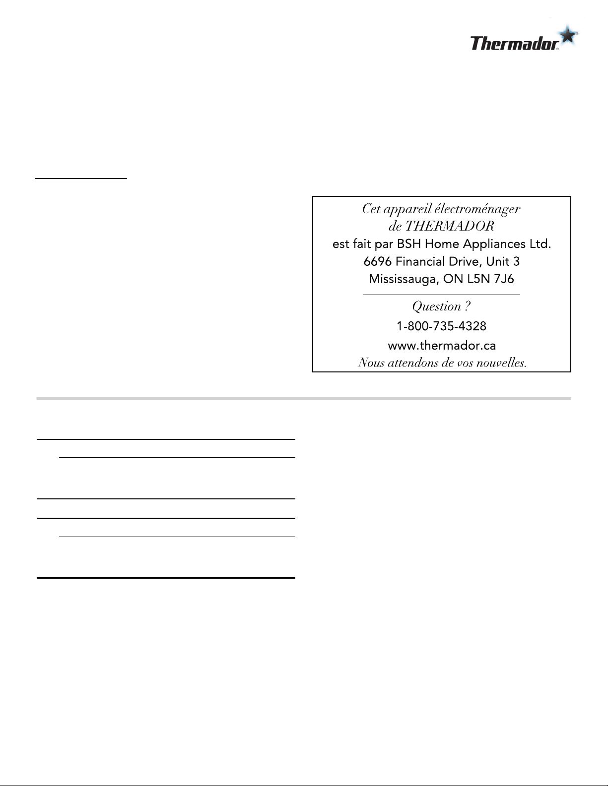
Table de
MATIÈRES
Table des matières
Noti ce de montage
9 Définitions de sécurité .......................................... 8
CONSIGNES DE SÉCURITÉ IMPORTANTES ................ 9
INSTRUCTIONS DE MISE À LA TERRE ........................... 9
Codes et normes de sécurité ........................................ 10
Installation et entretien corrects ................................... 10
Avertissement issu de la proposition 65 ...................... 11
Avant de commencer ............................................... 12
Pièces comprises ........................................................... 12
Procédure d'installation ............................................ 12
Installation du caisson télescopique ............................. 12
.
9 Définitions de sécurité
Défi nitions de sécurité
9 AVERTISSEMENT
Ceci indique que le non-respect de cet
avertissement peut entraîner des blessures graves,
voire la mort.
9 ATTENTION
Ceci indique que le non-respect de cet
avertissement peut entraîner des blessures légères
ou de gravité moyenne.
AVIS : Ceci indique que la non-conformité à cet avis de
sécurité peut entraîner des dégâts matériels ou
endommager l'appareil.
Remarque : Ceci vous signale des informations et/ou
indications importantes.
9
9 CONSIGNES DE SÉCURITÉ IMPORTANTES
LIRE ET CONSERVER CES INSTRUCTIONS
CONSI GNES DE SÉCURI TÉ IMPORTANTESLI RE ET CONS E RV E R CE S INSTRUCTIONS
INSTALLATEUR : Conservez ces consignes à l’intention
de l’inspecteur électrique local. Laissez ces consignes
avec l’appareil à l’intention du propriétaire. Montrez au
propriétaire l’emplacement du disjoncteur ou du fusible
du circuit. Identifiez sa position pour pouvoir le retrouver
facilement.
PROPRIÉTAIRE : Prière de conserver ces consignes
pour pouvoir s’y référer ultérieurement.
AVERTISSEMENT
Si l’information de ce guide n’est pas suivie exactement,
il peut en résulter un incendie ou un choc électrique
causant des dommages à la propriété, des blessures ou
la mort.
AVERTISSEMENT
AVERTISSEMENT
Couper l’alimentation du circuit électrique au boîtier à
fusibles ou des disjoncteurs et le verrouiller avant de
câbler cet appareil électroménager. Exigences : 120 V
c.a., 60 Hz et 15 A. Après la coupure de l’alimentation
électrique, laisser refroidir l’appareil électroménager
avant de procéder aux réparations.
AVERTISSEMENT
DISPOSITIF À FONCTIONNEMENT AUTOMATIQUE
Couper l’alimentation électrique avant toute réparation
pour réduire le risque de blessure.
AVERTISSEMENT
AFIN DE RÉDUIRE LES RISQUES D’INCENDIE, DE
CHOC ÉLECTRIQUE OU DE BLESSURES
CORPORELLES, VEUILLEZ SUIVRE LES INSTRUCTIONS
SUIVANTES :
▯ Utilisez cet appareil seulement de manière conforme à
l'usage prévu par le fabricant. Si vous avez des
questions, contactez le fabricant.
▯ Avant le nettoyage ou l'entretien de l'appareil, mettez-le
hors tension sur le tableau électrique et verrouillez les
dispositifs de sectionnement afin d'empêcher toute
remise sous tension accidentelle.
S'il est impossible de verrouiller les dispositifs de
sectionnement, fixez de manière sûre au tableau
électrique un dispositif d'alerte bien visible , par
exemple une étiquette.
AVERTISSEMENT
Ne réparez, remplacez, ni ne retirez aucune partie de
l'appareil, excepté si les manuels recommandent de le
faire. Une installation, un entretien ou une inspection
incorrects peuvent occasionner des blessures ou des
dommages matériels. Reportez-vous au présent manuel
pour obtenir des indications. Toute autre intervention doit
être effectuée par un technicien agréé.
AVERTISSEMENT
RISQUE D’ÉLECTROCUTION
INSTRUCTIONS DE MISE À LA TERRE
AVERTISSEMENT
Une mise à la terre inadéquate peut entraîner un risque
d'électrocution.
Cet appareil doit être mis à la terre. En cas de court-
circuit électrique, la mise à la terre réduira le risque de
choc électrique en offrant au courant électrique un fil
d'évacuation.
Si les consignes du présent manuel ne sont
pas suivies à la lettre, il y a un risque
d’incendie ou d’électrocution pouvant
entraîner des dommages matériels, des
blessures ou la mort.
- NE PAS conserver ou utiliser de l’essence ou d’autres
liquides et vapeurs inflammables à proximité de cet
appareil électroménager ou de tout autre appareil.
- QUE FAIRE SI VOUS PERCEVEZ UNE ODEUR DE
GAZ
NE PAS essayer de mettre un appareil
électroménager sous tension.
NE PAS toucher d’interrupteur de courant électrique.
NE PAS utiliser de téléphones dans l’édifice.
Communiquer immédiatement avec le fournisseur de
gaz depuis l’appareil téléphonique d’un voisin.
Respecter les directives du fournisseur de gaz.
S’il s’avère impossible de joindre le fournisseur de
gaz, communiquer avec les pompiers.
- Utiliser les services d’un technicien en réparation ou
d’une agence de réparations autorisés, ou le
fournisseur de gaz, pour procéder à l’installation et
aux réparations.
NE PAS enlever les raccords.
NE PAS utiliser de rallonge.
Tout manquement à ces directives peutentraîner
la mort ou un incendie ou un choc électrique.
9 CONSIGNES DE SÉCURITÉ IMPORTANTES
LIRE ET CONSERVER CES INSTRUCTIONS
10
S'assurer que l'appareil est installé et mis à la terre par
un technicien qualifié. L'installation, les connexions
électriques et la mise à la terre doivent être conformes à
tous les codes applicables.
S'il y a lieu, conformément au Code national de
l'électricité (ou au Code canadien de l'électricité), cet
appareil doit être installé sur un circuit de dérivation
séparé.
AVERTISSEMENT
Pour diminuer le risque d’incendie ou de choc électrique,
ne pas utiliser cette hotte avec des instruments de
contrôle de la vitesse extérieurs.
Codes et normes de sécurité
Cet appareil est conforme aux plus récentes versions de
l'une ou plus des normes suivantes :
▯ UL 507 - Ventilateurs électrique (Electric Fans)
▯ CAN/CSA C22.2 No. 113 - Ventilateurs et soufflantes
(Fans and Ventilators)
Il incombe au propriétaire et à l'installateur de déterminer
si des exigences et/ou normes additionnelles
s'appliquent pour des installations spécifiques.
Installation et entretien corrects
ATTENTION
Ne jamais modifier ni altérer la configuration de
l'appareil. Par exemple, ne pas retirer les pieds de
nivellement, les panneaux, les couvercles de câblage ou
les fixations/vis antibasculement.
ATTENTION
Appareil conçu exclusivement pour la ventilation
générale. Ne pas utiliser pour évacuer des matières et
vapeurs dangereuses ou explosives.
AVERTISSEMENT
Pour réduire les risques de feu, utiliser uniquement des
gaines en métal.
Utilisez les services d’un installateur qualifié.
Enlever le ruban adhésif et l’emballage avant d’utiliser
l’appareil. Détruire l’emballage après avoir déballé
l’appareil. Ne jamais laisser les enfants jouer avec les
matériaux de conditionnement.
AVERTISSEMENT
ATTENTION – AFIN DE RÉDUIRE LES RISQUES
D’INCENDIE, DE CHOC ÉLECTRIQUE OU DE
BLESSURES CORPORELLES, VEUILLEZ SUIVRE LES
INSTRUCTIONS SUIVANTES :
▯ Les travaux d’installation et de raccordement électrique
doivent être effectués par une personne qualifiée,
conformément aux codes et standards de construction,
y compris ceux concernant le feu.
▯ Assurez-vous que l'aération est suffisante pour
permettre la combustion et l'évacuation des gaz par le
conduit de cheminée d'un appareil à combustible afin
de prévenir le refoulement d'air. Respectez les
instructions du fabricant de l'appareil de chauffage et
les normes de sécurité, comme celles publiées par la
National Fire Protection Association (NFPA) et par la
American Society for Heating, Refrigeration and Air
Conditioning Engineers (ASHRAE), ainsi que par les
autorités locales.
▯ Lorsque vous faites une ouverture dans un mur ou un
plafond, veillez à ne pas endommager les fils
électriques ou les conduites qui y sont dissimulés.
▯ Les soufflantes canalisées doivent donner sur
l'extérieur.
AVERTISSEMENT
POUR RÉDUIRE LE RISQUE D'INCENDIE DE GRAISSE
DE CUISINIÈRE:
a.
Ne laissez jamais la surface de cuisson sans
surveillance à des températures élevées. Les
débordements causent de la fumée et les résidus
graisseux peuvent s'enflammer.. Faites chauffer les
huiles lentement à feu doux ou moyen.
b.
Faites toujours fonctionner la hotte lorsque vous
cuisinez à feu vif.
c.
Nettoyez les ventilateurs régulièrement. Ne laissez pas
la graisse s'accumuler sur le ventilateur ou sur le filtre.
d.
Utilisez des casseroles de taille appropriée. Utilisez
toujours des récipients adaptés à la taille de la surface
de cuisson.
Ne flambez jamais sous la hotte aspirante et ne travaillez
jamais avec une flamme nue. Une hotte aspirante en
marche aspire les flammes dans le filtre. Une hotte
aspirante en marche aspire les flammes dans le filtre. Ne
flambez jamais sous la hotte aspirante et ne travaillez
jamais avec une flamme nue. Une hotte aspirante en
marche aspire les flammes dans le filtre. Les dépôts de
graisse sur les filtre risquent alors de s'enflammer!
▯ L’appareil est lourd et son déplacement et
installation exigent au moins deux personnes
ou encore un équipement approprié.
▯ Des surfaces cachées peuvent avoir des
rebords tranchants. Faire attention en
manipulant l’appareil électroménager. Tout
manquement à cette consigne pourrait
entraîner des dommages matériels ou des
blessures.
11
9 CONSIGNES DE SÉCURITÉ IMPORTANTES
LIRE ET CONSERVER CES INSTRUCTIONS
AVERTISSEMENT
POUR RÉDUIRE LE RISQUE DE LÉSIONS
CORPORELLES EN CAS D'UN FEU DE FRITURE SUR
UNE CUISINIÈRE, OBSERVER CE QUI SUIT :
▯ ÉTOUFFER LES FLAMMES à l'aide d'un couvercle bien
hermétique, d'une tôle à biscuits ou d'un plateau en
métal, puis éteindre le brûleur. FAIRE ATTENTION À NE
PAS SE BRÛLER. Si les flammes ne s'éteignent pas
immédiatement, ÉVACUER LES LIEUX ET FAIRE
APPEL AU SERVICE D'INCENDIE.
▯ NE JAMAIS SOULEVER UNE POÊLE EN FLAMMES –
Vous pourriez vous brûler.
▯ NE PAS UTILISER D'EAU, y compris les chiffons ou
serviettes mouillées - une violente explosion de vapeur
pourrait se produire.
▯ Utiliser UNIQUEMENT un extincteur si :
- Vous savez que vous avez un extincteur de classe
ABC et comment l'utiliser.
- Le feu est petit et circonscrit à la zone où il a débuté.
- Le service d'incendie est appelé.
- Si l'on peut combattre le feu en ayant le dos vers une
sortie.
Avertissement issu de la proposition 65 :
Ce produit pourrait contenir un produit chimique reconnu
par l'État de la Californie comme cancérigène ou ayant
des effets nocifs sur la reproduction. Par conséquent,
l'emballage de votre produit pourrait porter l'étiquette
suivante, comme requis par la Californie :
&DQFHUHWGRPPDJHVjODUHSURGXFWLRQ
$9(57,66(0(17,668('(/$352326,7,21â'(/e7$7'(
$9(57,66(0(17
/$&$/,)251,(â
ZZZ3:DUQLQJVFDJRY
12
Avant de commencer
Avant de commencer
Pour certains modèles, il existe des caissons pour
masquer les gaines et des caissons télescopiques
facultatifs pouvant être utilisés pour combler l’espace
entre la hotte et le plafond à l’installation d’une hotte
murale.
Pièces comprises
▯ Quincaillerie(1):
▯ 5 x 45 mm vis d’installation du (4)
▯ 5.4 x 75 mm vis d’installation du (4)
▯ 4.2 x 8 mm vis d’installation du (11)
▯ 10 x 60 mm Chevilles d’ancrage (4)
▯ 8 x 40 mm Chevilles d’ancrage (4)
▯ Adaptateur Torx 20
▯ Supports de montage (2)
▯ Gabarit de montage (1)
Procédure d'installation
Procédure d’i nstallation
Installation du caisson télescopique
IMPORTANT : Fixer d’abord solidement la hotte
cheminée au mur après l’installation de l’équerre de
fixation du caisson, mais avant d’installer le caisson
télescopique de cheminée.
Fixation des équerres de fixation du caisson
télescopique
1.
Retirez délicatement le film de protection du couvercle
du conduit et du capot avant le début de l’installation.
Utilisez une main pour maintenir le couvercle de
conduit stable tandis que l’autre main enlève le film de
protection.
2.
Maintenez une hauteur minimum de 30 po (762 mm)
entre la face inférieure de la hotte et la surface de
cuisson lors de l’installation de la cheminée murale.
3.
Localisez les deux montants à l’emplacement de
fixation.
4.
Marquez la ligne centrale verticale de la hotte de
cuisinière. Assurez-vous que le la ligne traverse le
sommet du plafond.
5.
Localiser le gabarit de montage dans un angle de 90º
contre la ligne centrale récemment faite.
Modèle Caissons
HMWB30WS DC30MTW
HMWB361WS DC36MTW
HMWB36WS
HMWB481WS DC48MTW
Modèle A B
30" (762 mm) 11 3⁄4" (298 mm) 29 3⁄4" (756 mm)
36" (914 mm) 11 3⁄4" (298 mm) 35 3⁄4" (908 mm)
48" (1219 mm) 11 3⁄4" (298 mm) 48" (1219 mm)
w
NN
LQFKHVPP
"
#
.BYw
NN
.JOw
NN
w
NN
w
NN
w
N
N
L
Q
F
K
H
V
P
P
"
#
.
B
Y
w
N
N
.
J
O
w
N
N
N
N
w
N
N
N
w
NN
13
6.
Faire les trous en fonction del largeur de votre
couverture de conduit.
7.
Retirez le gabarit de montage et tournez-le
180°.Localisez le modèle contre la ligne centrale à
faites les autres trous. Installez les ancrages muraux
en fonction du matériau du mur (bois ou
contreplaqué).
8.
Fixez l’équerre de fixation du caisson à la partie
supérieure du plafond à l’aide de quatre vis de 5 x 45
mm (bois) ou quatre vis de 5.4 x 75 mm. Assurez-
vous que l’équerre de fixation soit de niveau.
9.
Insérez le caisson au complet en l’inclinant et faites-le
pivoter vers le mur.
10.
Tirez délicatement la partie supérieure du caisson vers
le haut. Vissez les côtés gauche et droite du caisson à
l’équerre de fixation avec les vis de 4.2 x 8 mm.
11.
À partir de l’intérieur de la hotte, vissez les vis de 4.2 x
8 mm fournies dans les trous des sections latérales et
avant du bas du caisson. La quantité de vis fournies
dépend de la taille de la hotte.
&
HQW
HUOLQ
H
5RRI
&HQ
W
H
UO
L
Q
H
R
Q
Z
D
O
O
'
,
0
5RRI
5RRI
P
P
P
P
´
'
X
FW
F
R
Y
H
U
/H
I
W
HG
JH
´
'X
F
W
FR
YHU
,
Q
VW
DOOD
W
LR
Q
K
R
O
H
V
´
'X
F
W
FRYHU
,Q
V
WDOODWLRQKR
O
HV
´
'X
FW
FRY
H
U
,QV
W
D
O
O
DWL
RQ
K
RO
HV
´
'X
F
W
FR
YH
U
/H
I
W
H
G
JH
´
'XF
WFRYH
U
/H
I
W
H
G
J
H
P
P
´
'
X
FW
F
R
Y
H
U
5
LJ
K
W
HG
J
H
´
'XF
W
F
R
YH
U
5
L
J
K
W
H
G
J
H
´
'
X
FW
FRYH
U
5LJ K
W
H
G
J
H
´
'XFWF
RYH
U
,
Q
VW
D
OO
D
W
LRQ
K
R
O
H
V
´
'
X
FW
F
R
Y
HU
,
Q
V
WDOOD
W
LRQKR
O
HV
´
'X
FWFR
YHU
,
Q
VW
DOODWLRQ
K
R
OH
V
&
HQWHUO
LQH
5R R I
'
,
0
5RRI
5RRI
PP
PP
´
'XFWFRYHU
/HIW HG
JH
´
'X
FWFRYHU
,
Q
VWDO ODWLRQKRO
H
V
V
´
'
XF
W
FRYHU
,
Q
V
WDOODWLRQ
KR
OH
V
´
'
X
FWFRYH
U
,
Q
V
W
D
O
O
DW
LRQ
KR
OHV
´
'X
FWFR
YH
U
/HIW H
G
JH
´
'
X
F
WFRYH
U
/HIW HG
JH
P
P
´
'XFWFR
YH
U
5LJ KW
HGJ
H
´
'
XF
W
FRYHU
5
L
J
KWHGJH
´
'XFW
FRY
HU
5LJ KWH GJ
H
´
'XFWFRYHU
,QVW
D
OODWLRQ
KROHV
H
´
'X
FW
FRY
H
U
,QVW
DOOD
W
LRQ
KROH
V
´
'X
FWFRYH
U
,QVW
DOO
DWLRQ KROHV
&HQ
WH
UO
L
Q
H
R
Q
Z
D
O
O
5RRI
5RRI
P
P
P
P
´
'X
FWFRYH
U
/H
I
W
H
G
J
H
´
'
X
FWFR
YH
U
,
QVW
D
OO
D
WLRQ
KROHV
´
'X
FWFRYH
U
,
Q
VW
D
OODWLRQ
KR
O
HV
´
'XF
W
F
R
Y
HU
,
QV
W
DO
ODW
L
R
Q
K
ROH
V
´
'X
FW
F
R
YH
U
/H
IWH
G
JH
´
'X
FW
F
R
YHU
/
HIW
HG
JH
P
P
´
'
X
FW
FR
YHU
5LJ
K
W
HGJH
´
'
X
FW
FRYH
U
5
LJKW
H
G
J
H
´
'XFW
F
R
YH
U
5LJ K
W
H
G
J
H
´
'XFWFRYH
U
,Q
VW
D
OO
DW
LR
Q
KROH
V
´
'
X
FWF
RYH
U
,
Q
V
WDOODWLRQK
R
O
H
V
´
'XFWFR
YHU
,
QVW
DOODW
L
R
Q
K
R
OH
V
ÍNDICE
Índice
Instrucciones de instalación
9 Definiciones de seguridad ................................... 14
INSTRUCCIONES DE SEGURIDAD IMPORTANTES ... 15
INSTRUCCIONES PARA LA CONEXIÓN A TIERRA ..... 15
Códigos y normas de seguridad ................................... 16
Instalación y mantenimiento adecuados ....................... 16
Advertencia en virtud de la Proposición 65 .................. 17
Antes de empezar .................................................... 18
Piezas incluidas ............................................................. 18
Procedimiento de instalación ................................... 18
Instalación de la cubierta telescópica del ducto .......... 18
.
9 Definiciones de seguridad
Defi niciones de seguridad
9 ADVERTENCIA
Esto indica que pueden producirse heridas graves
o incluso la muerte si no se cumple con esta
advertencia.
9 ATENCION
Esto indica que pueden producirse heridas leves o
moderadas si no se cumple con esta advertencia.
AVISO: Esto indica que pueden producirse daños en el
aparato o en los bienes si no se cumple con este aviso.
Nota: Esto alerta sobre información o sugerencias
importantes.
15
9 INSTRUCCIONES DE SEGURIDAD IMPORTANTES
LEA Y CONSERVE ESTAS INSTRUCCIONES
I NSTRUCCI ONES DE SEGURI DAD IMPORTANTESLEA Y CONSE RV E EST AS INSTRUCCIONES
INSTALADOR: Conservar estas instrucciones para que
las use el inspector de electricidad local. Dejar estas
instrucciones con esta unidad para el propietario.
Mostrar al propietario la ubicación del breaker del
circuito o del fusible. Marcarla para recordar más
fácilmente.
PROPIETARIO: Conserve estas instrucciones para
referencia futura.
ADVERTENCIA
Si no sigue la información de este manual exactamente,
se puede ocasionar un incendio o una descarga
eléctrica que puede causar daños materiales o lesiones
personales.
ADVERTENCIA
ADVERTENCIA
Apagar el circuito de alimentación eléctrica en el panel
de servicio y bloquear el panel antes de conectar los
cables de este aparato. Requisito: 120 VAC, 60 Hz 15 A.
Dejar que se enfríe el aparato después de apagar la
alimentación eléctrica y antes de realizar el
mantenimiento del aparato.
ADVERTENCIA
DISPOSITIVO CON FUNCIONAMIENTO AUTOMÁTICO
Para reducir el riesgo de sufrir lesiones, desconectar de
la fuente de alimentación antes de realizar el
mantenimiento.
ADVERTENCIA
PARA REDUCIR EL RIESGO DE INCENDIO, CHOQUE
ELÉCTRICO O LESIONES A LAS PERSONAS, OBSERVE
LAS SIGUIENTES RECOMENDACIONES:
▯ Utilice esta unidad sólo de la manera indicada por el
fabricante. Si tiene preguntas, póngase en contacto
con el fabricante.
▯ Antes de reparar o limpiar la unidad, desconecte el
suministro eléctrico en el panel de servicio y bloquee
el servicio desconectando las conexiones para evitar
que se encienda accidentalmente.
Cuando no pueda bloquearse la desconexión del
servicio, coloque un aviso prominente de advertencia,
como un letrero, en el panel de servicio.
ADVERTENCIA
No reparar, sustituir ni quitar ninguna pieza del
electrodoméstico a menos que se recomiende de forma
específica en los manuales.Una instalación, servicio o
mantenimiento inadecuados pueden causar lesiones o
daños materiales. Consultar este manual para recibir
ayuda. Todos los demás servicios debe realizarlos un
agente autorizado.
ADVERTENCIA
PELIGRO DE DESCARGA ELÉCTRICA
INSTRUCCIONES PARA LA CONEXIÓN A
TIERRA
ADVERTENCIA
La incorrecta conexión a tierra puede provocar un riesgo
de descarga eléctrica.
Este aparato debe estar conectado a tierra. En caso de
un cortocircuito eléctrico, la conexión a tierra reduce el
riesgo de descarga eléctrica proporcionando un cable
de escape para la corriente eléctrica.
Si no sigue la información de este manual
exactamente, se puede ocasionar un
incendio o una descarga eléctrica que
pueden causar daños materiales, lesiones
personales o la muerte.
- NO almacenar ni usar gasolina u otros vapores y
líquidos inflamables en la proximidad de este aparato
o cualquier otro.
- QUÉ HACER SI SE DETECTA OLOR A GAS
NO trate de encender ningún aparato.
NO toque ningún interruptor eléctrico.
NO utilice ningún teléfono en su edificio.
Llame inmediatamente a su proveedor de gas desde
un teléfono vecino. Siga las instrucciones del
proveedor de gas.
Si no puede contactar a su proveedor de gas,
comuníquese con el departamento de bomberos.
- La instalación y el mantenimiento deben ser
realizados por un servicio técnico autorizado, una
agencia de servicio técnico o por el proveedor de
gas.
NO retirar las conexiones.
NO usar un cable de extensión.
No seguir estas instrucciones puede producir la
muerte o una descarga eléctrica.
9 INSTRUCCIONES DE SEGURIDAD IMPORTANTES
LEA Y CONSERVE ESTAS INSTRUCCIONES
16
Asegúrese de que el electrodoméstico sea
correctamente instalado y conectado a tierra por un
técnico calificado. La instalación, las conexiones
eléctricas y la conexión a tierra deben cumplir con todos
los códigos correspondientes.
Si el Código Nacional Eléctrico (o el Código Eléctrico
Canadiense) así lo requiere, este electrodoméstico debe
instalarse en un circuito derivado por separado.
ADVERTENCIA
Para reducir el riesgo de incendios o descarga eléctrica,
no usar esta campana con cualquier dispositivo de
mando de velocidad sólido externo.
Códigos y normas de seguridad
Este electrodoméstico cumple con la última versión de
una o varias de las siguientes normas:
▯ UL 507 - Ventiladores eléctricos (Electric Fans)
▯ CAN/CSA C22.2 No. 113 - Ventiladores (Fans and
Ventilators)
Es responsabilidad del propietario y del instalador
determinar si se aplican otros requisitos o normas en
instalaciones específicas.
Instalación y mantenimiento adecuados
ATENCION
Nunca modifique ni altere la construcción del
electrodoméstico. Por ejemplo, no retire las patas
niveladoras, paneles, cubiertas para cables ni soportes/
tornillos antivuelco.
ATENCION
Solo para la ventilación general. No utilizar para la
extracción de sustancias y vapores peligrosos o
explosivos.
ADVERTENCIA
A fin de reducir el riesgo de incendio, utilizar únicamente
conducciones de metal.
Usar un instalador calificado.
Retire toda la cinta y el embalaje antes de usar el
electrodoméstico. Destruya el embalaje después de
desembalar el electrodoméstico. Nunca deje que los
niños jueguen con el material de embalaje.
ADVERTENCIA
ADVERTENCIA – PARA REDUCIR EL RIESGO DE
INCENDIO, CHOQUE ELÉCTRICO O LESIONES A LAS
PERSONAS, OBSERVE LAS SIGUIENTES
RECOMENDACIONES:
▯ El trabajo de instalación y el cableado eléctrico deben
realizarse por personal calificado conforme a todos los
códigos y estándares aplicables, incluyendo
construcción contra incendios.
▯ Se requiere suficiente aire para la combustión y
escape adecuado de gases por el conducto
(chimenea) del equipo que quema combustible para
evitar la contracorriente. Siga la directriz y las normas
de seguridad del fabricante de equipos de
calefacción, como las publicadas por La Asociación
Nacional para la Protección contra Incendios (NFPA,
por sus siglas en inglés) y la Sociedad Americana de
Ingenieros en Calefacción, Refrigeración y Aire
Acondicionado (ASHRAE, por sus siglas en inglés) y
las autoridades locales correspondientes.
▯ Al cortar o perforar la pared o el techo, no dañe el
cableado eléctrico u otras instalaciones ocultas.
▯ Los ventiladores entubados siempre deben ser
ventilados hacia el exterior.
ADVERTENCIA
PARA REDUCIR EL RIESGO DE INCENDIO
OCASIONADO POR LA GRASA EN LA ESTUFA:
a.
Nunca deje las unidades de la superficie sin vigilancia
en valores altos. Los derrames por hervor producen
humos y salpicaduras grasosas que pueden prenderse
fuego. Caliente los aceites despacio a temperaturas
bajas o medianas.
b.
Siempre encienda la campana al cocinar a una
temperatura alta.
c.
Limpie los ventiladores extractores con frecuencia. No
se debe permitir la acumulación de la grasa en el
ventilador ni en el filtro.
d.
Use el tamaño de cacerola adecuado. Siempre use
utensilios de cocina apropiados para el tamaño del
elemento de la superficie.
No flambee alimentos bajo la campana no decorativa ni
trabaje con la llama abierta. Cuando está encendida, la
campana extractora atrae las llamas hacia el filtro.
¡Siempre existe el riesgo de incendio debido a los
depósitos en el filtro de grasa!
▯ La unidad es pesada y se requieren al menos
dos personas o un equipo adecuado para
trasladarla e instalarla.
▯ Las superficies ocultas podrían tener bordes
afilados. Tener cuidado al manejar el
electrodoméstico. No hacerlo puede causar
daños materiales o lesiones personales.

17
9 INSTRUCCIONES DE SEGURIDAD IMPORTANTES
LEA Y CONSERVE ESTAS INSTRUCCIONES
ADVERTENCIA
PARA REDUCIR EL RIESGO DE LESIONES A
PERSONAS EN CASO DE INCENDIO OCASIONADO
POR GRASA EN LA ESTUFA, SIGA ESTAS
INDICACIONES:
▯ SOFOQUE LAS LLAMAS con una tapa que ajuste
correctamente, una placa para galletas u otra bandeja
de metal; luego, apague la hornilla. ASEGÚRESE DE
PREVENIR LAS QUEMADURAS. Si las llamas no se
apagan de inmediato, EVACUE EL ÁREA Y LLAME AL
DEPARTAMENTO DE BOMBEROS.
▯ NUNCA LEVANTE UNA OLLA EN LLAMAS ya que se
puede quemar.
▯ NO USE AGUA, ni toallas o repasadores húmedos, ya
que puede ocasionar una violenta explosión por vapor.
▯ Use un extinguidor SÓLO si:
- Sabe que tiene un extinguidor Clase ABC y ya sabe
cómo usarlo.
- El incendio es pequeño y se limita al área donde se
originó.
- Alguien llamó al departamento de bomberos.
- Puede combatir el incendio de espaldas a una
salida.
Advertencia en virtud de la
Proposición 65:
Este producto puede contener un químico que el Estado
de California reconoce como potencialmente
cancerígeno o causante de daños reproductivos. Por
tanto, su producto debe llevar en su embalaje la
siguiente etiqueta de conformidad con la legislación de
California:
&iQFHU\GDxRUHSURGXFWLYRZZZ3:DUQLQJVFDJRY
$'9(57(1&,$(19,578''(/$352326,&,Ð1'(/
$'9(57(1&,$
(67$'2'(&$/,)251,$

18
Antes de empezar
Antes de empezar
En algunos modelos se pueden usar cubiertas del ducto
opcionales y extensiones telescópicas para llenar el
espacio entre la campana extractora y el techo en
instalaciones en pared.
Piezas incluidas
▯ Bolsa con tornillería (1):
▯ 5 x 45 mm tornillos de instalación (4)
▯ 5.4 x 75 mm tornillos de instalación (4)
▯ 4.2 x 8 mm tornillos de instalación (11)
▯ 10 x 60 mm taquetes (4)
▯ 8 x 40 mm taquetes (4)
▯ Adaptador Torx 20
▯ Sujesores de cubre ducto duperior (2)
▯ Plantilla de instalación (1)
Procedimiento de instalación
Procedimiento de instalación
Instalación de la cubierta telescópica del
ducto
IMPORTANTE: Asegurar la chimenea de la campana
extractora a la pared después de instalar la placa de
fijación del montaje de la extensión, pero antes de
instalar la extensión telescópica de la chimenea.
Instalación de la cubierta telescópica de ductos
1.
Retire con cuidado la película protectora de la
cubierta del conducto y del ensamble de la campana
antes del inicio de la instalación. Use una mano para
mantener la cubierta del ducto estable mientras la otra
mano retira la película protectora.
2.
Asegurarse de que se mantiene la altura mínima de
30” (762 mm) desde la parte inferior de la campana
hasta la superficie de cocción.
3.
Situar dos refuerzos en el lugar de la instalación.
4.
Marque la línea central vertical de la campana
extractora. Asegúrese de que la línea atraviese hasta
la parte superior del techo.
5.
Ubique la plantilla de montaje en un ángulo de 90º
contra la línea central recientemente hecha.
Modelos de campana Cubre ductos
HMWB30WS DC30MTW
HMWB361WS DC36MTW
HMWB36WS
HMWB481WS DC48MTW
Modelo A B
30" (762 mm) 11 3⁄4" (298 mm) 29 3⁄4" (756 mm)
36" (910 mm) 11 3⁄4" (298 mm) 35 3⁄4" (908 mm)
48" (1220 mm) 11 3⁄4" (298 mm) 48" (1219 mm)
w
NN
LQFKHVPP
"
#
.BYw
NN
.JOw
NN
w
NN
w
NN
w
N
N
L
Q
F
K
H
V
P
P
"
#
.
B
Y
w
N
N
.
J
O
w
N
N
N
N
w
N
N
N
w
NN
19
6.
Haga los agujeros guía según el ancho de la cubierta
del conducto.
7.
Retire la plantilla de montaje y gírela 180°. Ubique la
plantilla contra la línea central para hacer los otros
agujeros piloto. Installe los taquetes dependiendo del
material de su pared (madera o tablaroca).
8.
Instale los soportes de cubreductos en la parte
superior del techo usando 4 tornillos de 5 x 45 mm
(madera) o 4 tornillos de 5.4 x 75 mm (tablaroca).
Asegúrese de que ambos soportes estén nivelados
horizontalmente.
9.
Inserte la cubierta completa del conducto en un
ángulo y gírelo hacia la pared.
10.
Tire con cuidado de la parte superior de la extensión
hacia arriba. Atornille los lados izquierdo y derecho de
la extensión al soporte de montaje con los tornillos de
4.2 x 8 mm suministrados.
11.
Desde el interior de la campana, atornille los tornillos
de chapa de 4.2 x 8 mm suministrados a través de los
orificios de cada lado y a lo largo de la parte delantera
en la parte inferior de la extensión.
&
HQW
HUOLQ
H
5RRI
&HQ
W
H
UO
L
Q
H
R
Q
Z
D
O
O
'
,
0
5RRI
5RRI
P
P
P
P
´
'
X
FW
F
R
Y
H
U
/H
I
W
HG
JH
´
'X
F
W
FR
YHU
,
Q
VW
DOOD
W
LR
Q
K
R
O
H
V
´
'X
F
W
FRYHU
,Q
V
WDOODWLRQKR
O
HV
´
'X
FW
FRY
H
U
,QV
W
D
O
O
DWL
RQ
K
RO
HV
´
'X
F
W
FR
YH
U
/H
I
W
H
G
JH
´
'XF
WFRYH
U
/H
I
W
H
G
J
H
P
P
´
'
X
FW
F
R
Y
H
U
5
LJ
K
W
HG
J
H
´
'XF
W
F
R
YH
U
5
L
J
K
W
H
G
J
H
´
'
X
FW
FRYH
U
5LJ K
W
H
G
J
H
´
'XFWF
RYH
U
,
Q
VW
D
OO
D
W
LRQ
K
R
O
H
V
´
'
X
FW
F
R
Y
HU
,
Q
V
WDOOD
W
LRQKR
O
HV
´
'X
FWFR
YHU
,
Q
VW
DOODWLRQ
K
R
OH
V
&
HQWHUO
LQH
5R R I
'
,
0
5RRI
5RRI
PP
PP
´
'XFWFRYHU
/HIW HG
JH
´
'X
FWFRYHU
,
Q
VWDO ODWLR
Q
KRO
H
V
V
´
'
XF
W
FRYHU
,Q
VWDO ODWLR
Q
KR
OH
V
´
'
X
FWFRYH
U
,
Q
V
W
DOO
DWLRQ
KR
OHV
´
'X
FWFR
YH
U
/HIW H
GJH
´
'XF
WFRYH
U
/HIW HG
JH
P
P
´
'XFWFR
YH
U
5LJ KW
HGJ
H
´
'XF
W
FRYHU
5
L
J
KWHGJH
´
'XFWFRYHU
5LJ KWH GJ
H
´
'XFWFRYH
U
,QVWDOODWLRQKROHV
H
´
'X
FW
FRY
H
U
,QVW
DOOD
W
LRQ
K
R
OH
V
´
'X
FWFRYH
U
,Q
VW
D
OODW
LRQ
KR
OHV
&HQ
WH
UO
L
Q
H
R
Q
Z
D
O
O
5RRI
5RRI
P
P
P
P
´
'X
FWFRYH
U
/H
I
W
HG
J
H
´
'
X
FWFRYH
U
,QVW
D
OO
D
W
LRQ
KROHV
´
'X
FWFR
Y
H
U
,
Q
VW
D
OODWLRQ
KR
O
HV
´
'XF
W
F
R
Y
HU
,
Q
VW
DO
ODWL
RQ
K
RO
H
V
´
'XFW
F
R
YH
U
/HIWH
G
JH
´
'X
FW
F
R
YHU
/
HIW
HG
JH
P
P
´
'
X
FW
FR
Y
HU
5LJ
K
W
HGJH
´
'
X
FW
FRYH
U
5
LJKW
H
G
J
H
´
'XFW
F
R
YH
U
5LJ K
W
HG
JH
´
'
X
FWF
RYHU
,Q
VW
D
O
O
DW
LR
Q
K
ROH
V
´
'
X
FW
F
RYH
U
,
Q
V
WDOODW
L
RQK
R
O
H
V
´
'
X
FWFR
YHU
,
QV
WDOODWL
R
Q
K
R
OH
V


1901 MAIN STREET, SUITE 600 IRVINE, CA 92614 // 1-800-735-4328 // WWW.THERMADOR.COM
© 2020 BSH HOME APPLIANCES CORPORATION
9001523050 en-us, es-mx, fr-ca 000513
*9001523050*