Loading ...
Loading ...
3
INSTALLATION
WARNING: To reduce the risk of fire, do not store
or use gasoline or other flammable vapors and
liquids in the vicinity of the heater.
CAUTION: High temperature, risk of fire, keep
electrical cords, drapery, furnishings, and
other combustibles at least 3 feet (0.9 m) from
the front of the heater and away from the side
and rear.
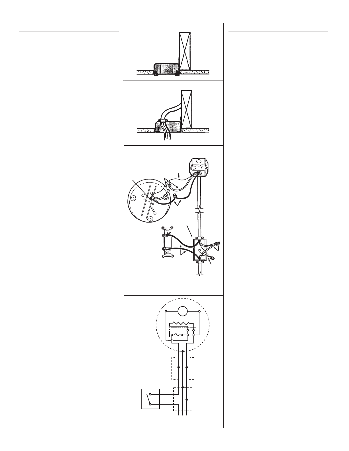
1. Mount electrical box. (FIG. 2)
Position electrical box flush or slightly recessed
in ceiling and mount it securely.
Installation work and electrical wiring must be
done by a qualified person(s) in accordance
with all applicable codes and standards,
including fire-rated construction codes and
standards.
2. Connect wiring. (FIG. 3)
Run electrical cable into box and secure with
appropriate connector. Allow 6" of wire inside
box.
3. Wire the heater. (FIGS. 4 & 5)
Attach electrical power cable to heater. Connect
black to black, white to white, and green or bare
wire to ground screw.
Complete the wiring by adding a wall control.
Follow the pictorial or schematic diagram.
INSTALACION
ADVERTENCIA: Para reducir el riesgo de
incendio, no almacene ni use gasolina u otros
vapores y líquidos flamables en las cercanías
del calentador.
PRECAUCIÓN: Temperatura alta, el riesgo
de incendio, mantenga los cables eléctricos,
cortinas, muebles y otros materiales
combustibles por lo menos 3 pies (0,9 m) del
frente del calentador y lejos de la cara y la
parte trasera.
1. Monte la caja eléctrica. (FIG. 2)
Coloque la caja eléctrica a nivel o un poco
hacia adentro en el cielo raso y fíjela de forma
segura.
El trabajo de instalación y el cableado eléctrico
deben estar a cargo de personal capacitado,
de acuerdo con todos los códigos y normas
correspondientes, incluidos los códigos y
normas de construcción específicos sobre
protección contra incendios.
2. Conecte el cableado. (FIG. 3)
Coloque el cable eléctrico en la caja y
asegúrelo con el conector apropiado. Deje
15,24 cm (6 pulg.) de cable dentro de la caja.
3. Cableado del calentador. (FIGS. 4 & 5)
Enchufe el cable de energía eléctrica al
calentador. Conecte negro a negro, blanco a
blanco, y cable verde o descubierto al tornillo
de tierra.
Complete el cableado agregando un control
de pared. Siga el diagrama de figuras o
esquemático.
FIG. 5
FIG. 4
GROUND TIERRA
BLACK
NEGRO
120 VCA 60 HZ
LINE IN
LINEA DE ENTRADA
DE 120 VCA 60
HZ
GROUND
SCREW
TORNILLO
DE TIERRA
GREEN OR
BARE WIRE
ALAMBRE
VERDE O
DESCUBIERTO
WHITE
BLANCO
BLACK
NEGRO
SWITCH BOX
CAJA DEL INTER-
RUPTOR
TOGGLE SWITCH TIM-
ER OR THERMOSTAT
TEMPORIZADOR DE
INTERRUPTOR DE
PALANCA ACODILLADA
O TERMOSTATO
WHITE BLANCO
M
HEATING ELEMENT
ELEMENTO DE CALOR
BLACK
NEGRO
BLACK
NEGRO
GROUND / TIERRA
WHITE
BLANCO
BLACK
NEGRO
WHITE
BLANCO
GROUND
TIERRA
WHITE
BLANCO
120 VAC LINE IN
LINEA DE ENTRADA
120 VCA
SWITCH BOX
CAJA DE
INTERRUPTORES
TOGGLE SWITCH, TIMER,
OR THERMOSTAT
TEMPORIZADOR DE
INTERRUPTOR, DE
PALANCA ACODILLADA,
O TERMOSTATO
CEILING BOX
CAJA DE
CIELO RASO
THERMAL CUTOFF
TERMICA
INTERRUPTOR
FIG. 2
FIG. 3
Loading ...
Loading ...
Loading ...