
Loading ...
Loading ...
Loading ...
SHAVE PLATE AND SKiD SHOES
Theshaveplateand skid shoeson the bottomof the snowthrowerare
subjectto wear.They shouldbe checkedperiodicallyand replaced
whennecessary.
NOTE:Theskidshoeson this machinehavetwo wearedges.When
onesidewearsout, theycan be rotated1800to usethe otheredge.
Toremoveskidshoes:
1. Removethefour carriagebolts and hexflangenuts which secure
themtothe snowthrower.
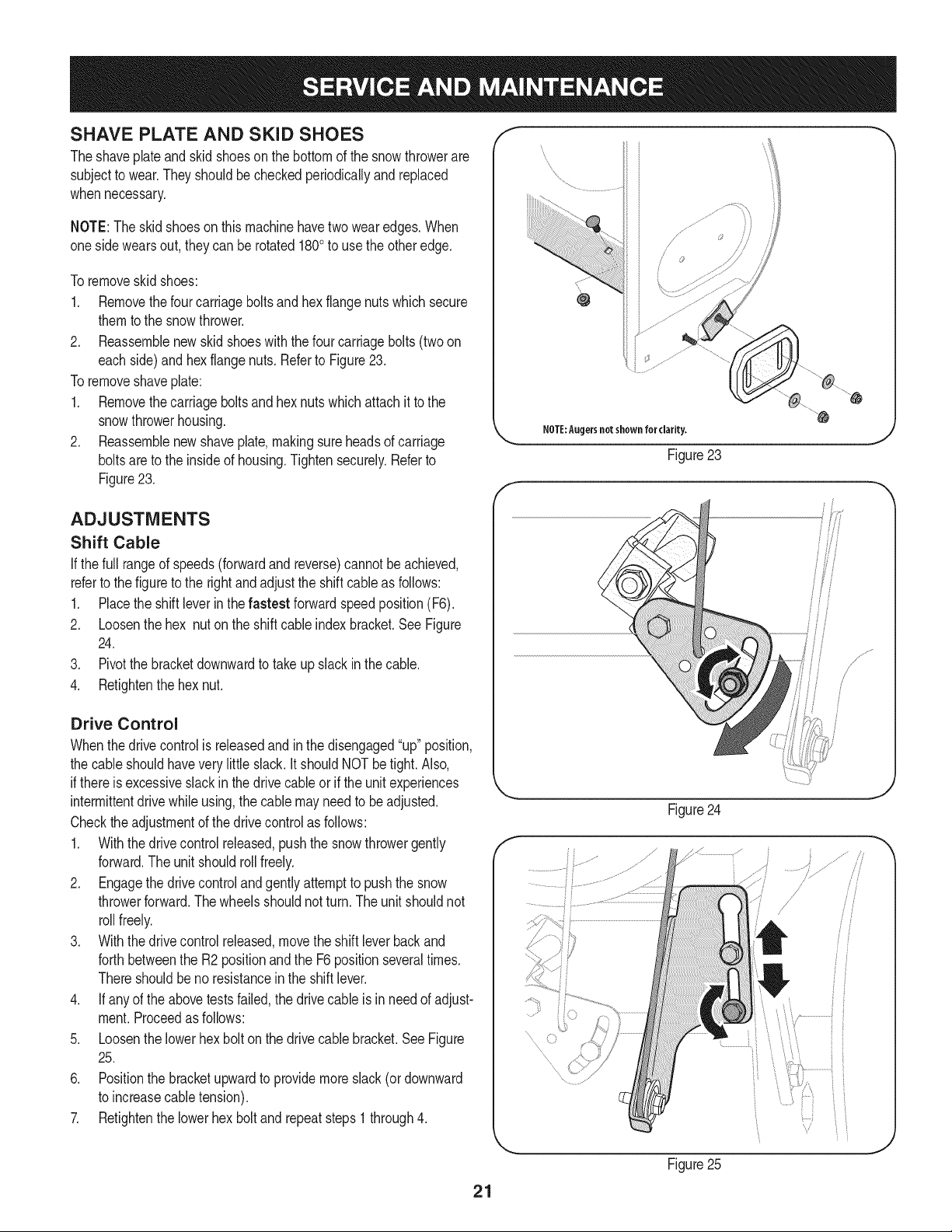
2. Reassemblenew skid shoeswith thefour carriagebolts (two on
eachside)and hexflangenuts.Referto Figure23.
Toremoveshaveplate:
1. Removethecarriageboltsand hexnuts whichattachit to the
snowthrowerhousing.
2. Reassemblenew shaveplate,makingsureheadsof carriage
boltsare to the insideof housing.Tightensecurely.Referto
Figure23.
NOTE:Augersnotshown for clarity.
Figure23
ADJUSTMENTS
Shift Cable
If thefull rangeof speeds(forwardandreverse)cannotbe achieved,
referto the figureto the rightand adjustthe shift cableas follows:
1. Placethe shiftleverin thefastest forwardspeedposition(F6).
2. Loosenthe hex nuton the shiftcable indexbracket.See Figure
24.
3. Pivotthe bracketdownwardto take up slack in the cable.
4. Retightenthehex nut.
Drive Control
Whenthedrivecontrolis releasedandin thedisengaged"up"position,
the cableshouldhaveverylittle slack.It shouldNOTbetight. Also,
if thereis excessiveslackin thedrive cableor if the unitexperiences
intermittentdrivewhileusing,the cable mayneed to beadjusted.
Checktheadjustmentof the drivecontrolas follows:
1. Withthedrivecontrolreleased,pushthe snowthrowergently
forward.The unitshouldrollfreely.
2. Engagethe drivecontroland gently attemptto pushthe snow
throwerforward.Thewheelsshouldnotturn.The unitshouldnot
rollfreely.
3. With thedrivecontrol released,movethe shift leverbackand
forthbetweenthe R2positionand the F6 positionseveraltimes.
Thereshouldbeno resistancein the shiftlever.
4. If anyof the abovetests failed,the drivecable is in needof adjust-
ment.Proceedas follows:
5. Loosenthe lowerhexbolt on the drivecable bracket.SeeFigure
25.
6. Positionthe bracketupwardto providemoreslack(or downward
to increasecabletension).
7. Retightenthe lowerhex boltand repeatsteps1 through4.
f
Figure24
........
Figure25
/
21
Loading ...
Loading ...
Loading ...