Loading ...
Loading ...
Loading ...
8 31-5000496 Rev. 2
Installation Instructions
Console Installation
Step 5. Piping Configuration and
Installation
B. Line sets
• The standard line set length is 25 feet. If the
installation length is different, adjust the refrigerant
charge by 0.2 oz/ft if the liquid line is 1/4”, or 0.5 oz/ft
if the liquid line is 3/8”.
• Make sure the line sets are fully insulated, including
the flare connection.
• Coat the outside of the flare with refrigerant oil and
connect pipes.
• To join the line set, directly align the tubing flare to the
fitting on the other pipe. Slide the nut onto the fitting
and hand tighten.
• •
•
•
I
t
,
I
I
X
[
1
tD IHl I jo
7
I
7
7-1/8
(181)
8-3/
4
(223)
NOTE: Follow standard practices for creating pipe
flares. When cutting and reaming the tubing, use
caution to prevent dirt or debris from entering the tubing.
Remember to place nut over the tubing before flaring.
Torque Specifications
Torque the fittings according to the specifications
shown in the torque chart below.
Pipe Diameter φ Fastening torque
Liquid side 6.35mm (1/4”) 18N.m/13.3Ft.lbs
Liquid/Gas side 9.52mm (3/8”) 42 N.m/30.1Ft.lbs
Gas Side 12.7mm (1/2”) 55N.m/40.6Ft.lbs
Gas side 15.88mm (5/8”) 60 N.m/44.3Ft.lbs
• Two wrenches are required to join the flare
connection; one standard wrench and one torque
wrench adjusted to the proper settings.
• Repeat the process for attaching the other end of the
line set.
Console Installation
Step 5. Piping Configuration and
Installation
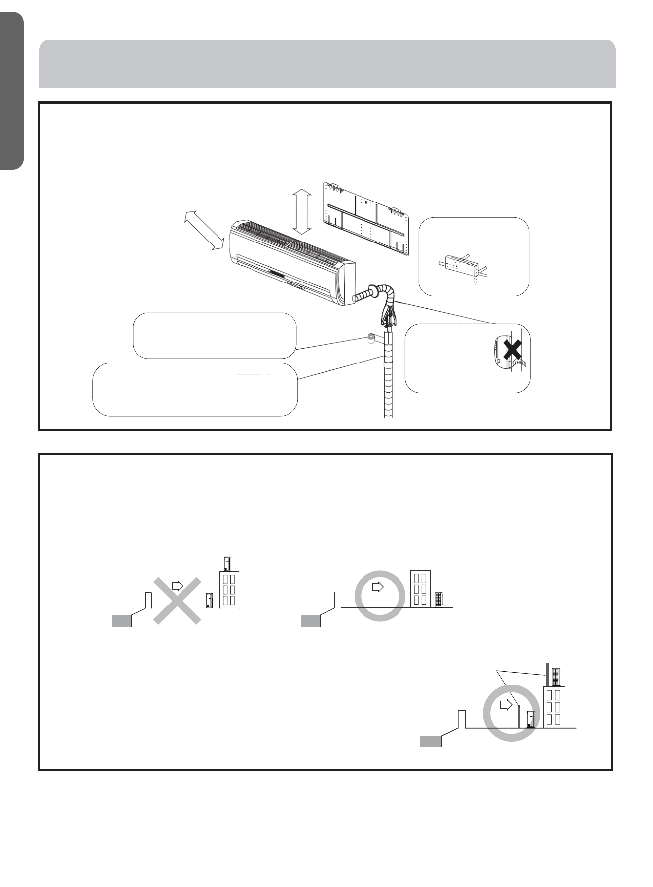
C. Condensate Piping
1. If the condensate drain hose passes through an
interior space, ensure it is properly insulated.
2. The drain hose should have a downward slope
to allow for proper condensate flow. The use of a
condensate pump will be required if a downward
slope can not be achieved.
3. Drain hose diameter should be equal to, or larger
than that of the factory piping (φ 5/8” [16.5mm]).
Downward
sloped
Raised
Waved
End submerged
in water
Loading ...
Loading ...
Loading ...