Loading ...
Loading ...
Loading ...
INSTALLATION
Check the appliance is electrically safe when you have nished.
32
A
B
A
B
Cooker
Outer stability
bracket
Floor
Wall
3 mm min
Typical wall mounting
ArtNo.280-0030 - Fixing Flue Grill
ArtNo.070-0014 - Stability bracket - Wall fitting
Cooker
Stability bracket
Floor
3 mm min
Typical oor mounting
Anti-tip bracket
Range
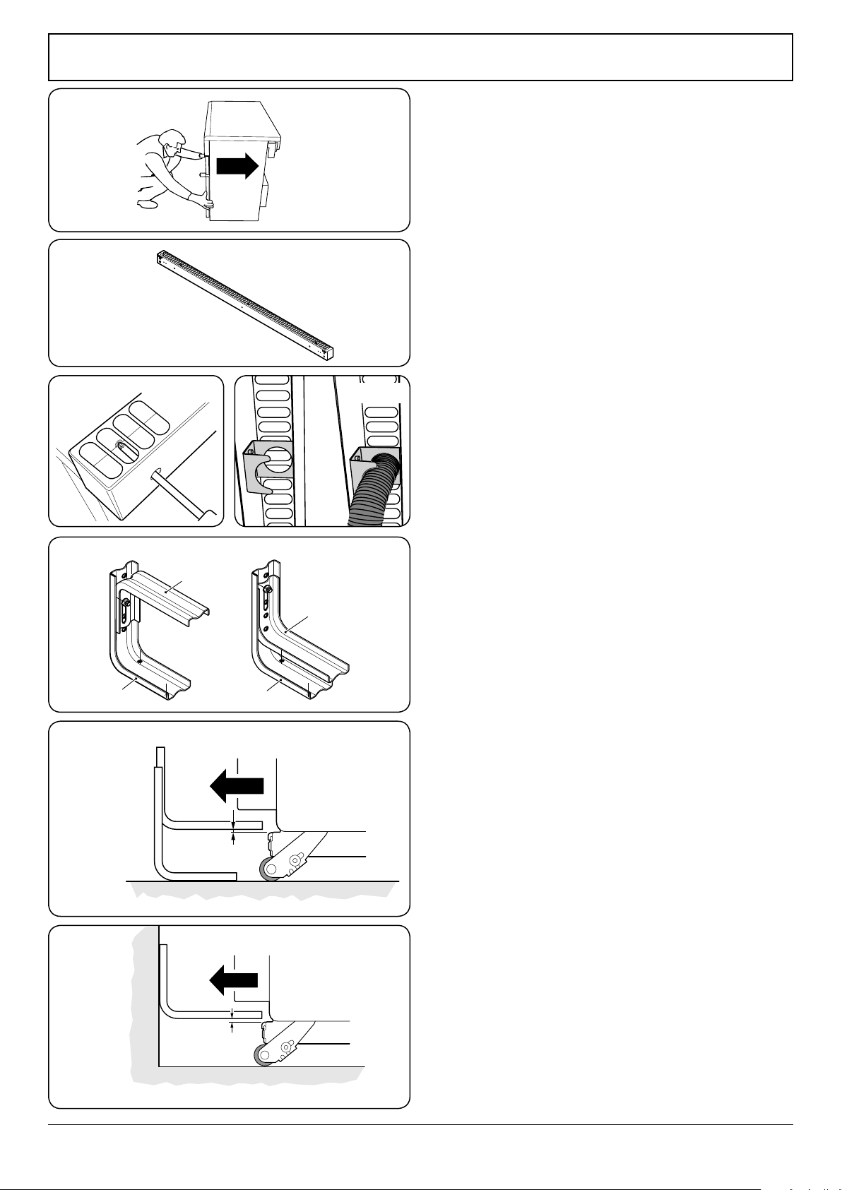
Position the range close to its nal position, leaving just
enough space to get behind it (Fig. 11.9).
IMPORTANT: Remove all tape and packaging. Make sure
the burner heads are properly seated and level. Take
the accessory pack out of the oven. Check to be sure
that no range parts have come loose during shipping.
Installing the flue grille
The ue grille is packed separately (Fig. 11.10).
The larger of the holes along the sides are for screwdriver
access and should face to the rear. Use the screws supplied to
hold the grille in place (Fig. 11.11).
Clip the exible extension of the oven ue to the ue grille
using the clip provided inside the ue grille (Fig. 11.12).
Leveling
It is recommended that you use a spirit level on a shelf in the
oven to check the level.
Place the range in its intended position, taking care not to
twist it within the gap between the kitchen units as damage
may occur to the range or the units.
The front feet and rear rollers can be adjusted to level the
range. To adjust the height of the rear of the range turn the
adjusting nuts at the front bottom corners of the range.
Anti-tip device
n
WARNING: The range must be secured using the
anti-tip bracket supplied. Unless properly installed,
the range could be tipped by leaning on the door.
Injury might result from spilled hot liquids or from
the range itself.
When tting an anti-tip device, please refer to the instructions
supplied with the device for further details on tting.
NOTE: The range must be set to the correct height and
leveled before the anti-tip bracket is installed.
Floor fixing
Using the screw supplied, assemble the anti-tip bracket base
and anti-tip bracket extension (Fig. 11.12).
Using suitable screws and xings, attach the assembled anti-
tip bracket to the oor to ensure sucient engagement with
the back of the range.
Adjust and lock the inner anti-tip bracket to give a ⁄” (3 mm)
clearance above the engagement edge in the back of the
range (Fig. 11.13).
Wall fixing
Where oor xing is impractical and provided that the outer
anti-tip bracket can be attached to a solid wall, the anti-tip
device may be attached to a wall (Fig. 11.15). Make sure to
use suitable screws and xings.
Fig. 11.10
Fig. 11.11 Fig. 11.12
Fig. 11.13
Fig. 11.14
Fig. 11.15
Range
1/8” (3mm) min
1/8” (3mm) min
Outer anti-tip bracket
Fig. 11.9
Loading ...
Loading ...
Loading ...