Loading ...
Loading ...
Loading ...
.HI. I001tN 341.1H! tN
2Ca.? IIEtDLE UAII Iltl_ltT ANOORItNTATION 2C.2.3 CLFARANCtILrTWttN 80181N CASI_
NOLDtRAND80RIIN _.A$1STOP
) CHECKINGNEEDLEBARORIENTATION
Needle bar onPntahon is wdhm specd,'ahon when ghl side bar of panqe No 68933 is hetween zero and 060 inch 11 ,_
rum) of parallel hoe wdh Iron: edge ol needle f.lale See Fiqt,r_"o .',r,, 21 and ,72
• The 060 inches 11 5 mm) position wall improve machine performance when using stretch lhread_
IFrom'es 21 and221 This 060 inch Iwasl given to the needle bar wall make ateasier for the hdok tip
to lOCk up the I_read loop
• Innoraseshouldthe lefthandrod Iratherthanthe rtghlrodtbeclosertotheplateedge(Figure
22J
4 AI1JLISTiNGNEEDLEBARORIENTATION
• ToadpJsl,loosenscrewIA) (,Crgute201androlale the needlebarasreqo,ed forproperadloslment
Re fateful nutfo change needlehat height Tightenstrew IAr securely Removega,(le andimnstall
hobbmrase needle needle plate presserfool and bohhmcase slop
• Adlusl the poslhon ol bobbin case stop Refer to Sectmn 2C2 3
A
No. 68933
FIGURE 20
No. 68933
FIGURE21
0
FIGURE 22
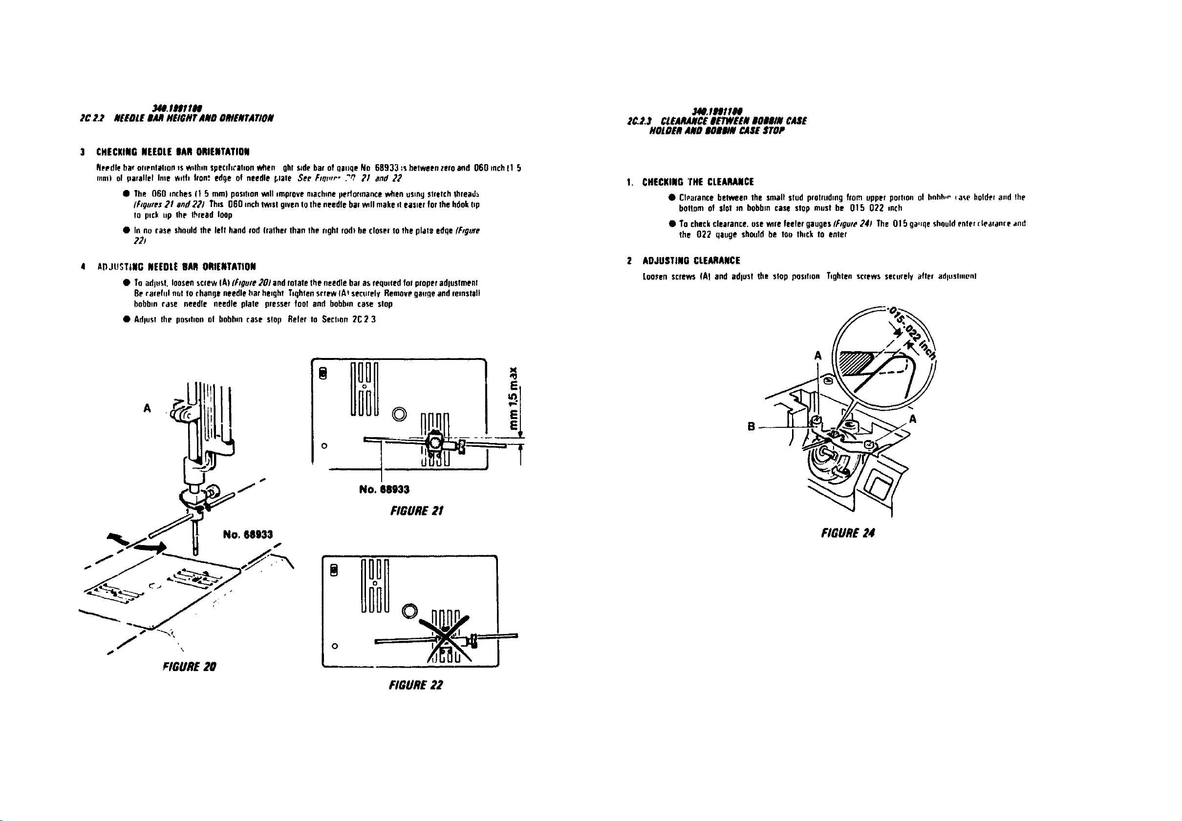
. CHECKING THE CLEARANCE
• CIParancebetween the small stud protrudingfrom upper port,on ol hnhh,r"qa_,eholdera,d the
boltom of slot rn bobbincase slop must he 015 022 inch
• Tocheckclearance,use warefeeler gaugesIF_gute241 The O15ga._qeshould enter(learanre and
the 022 qaoge should be log lh_cklo enler
2 ADJUSTING CLEARANCE
Loosenscrews (A) and adlUSl the slop position Tightenscrews ser:urolyafire adlnsluignt
/
A
FIGURE 24
Loading ...
Loading ...
Loading ...