Loading ...
Loading ...
Loading ...
INSTALLATIONREQUIREMENTS
Gather the required tools and parts before starting installation.
Read and follow the instructions provided with any tools
listed here.
Tools needed
[] 200 mm (8") or 250 mm [] 8 mm (sA0")socket wrench
(10") Pipe wrench [] Utility knife
[] 200 mm (8") or 250 mm [] Vent clamps
(10") adjustable wrench
[] Sealing compound gun
[] Flat-blade screwdriver and sealing compound
[] Phillips screwdriver (for installing new
[] Adjustable wrench that exhaust vent)
opens to 2.5 cm (1") or [] Pliers
hex-head socket wrench [] Putty knife
[] Level
Parts supplied
Remove parts bag from dryer drum. Check that all parts were
included.
[] Foot boot (4)
[] Dryer foot (4)
NOTE: The circuit diagram for this machine is located inside the
lower front panel.
Explosion Hazard
Keep fiammab{e materials and vapors, such as petrol,
away from dryer.
Do not install in a garage.
Failure to do so can result in death, explosion, or fire.
IMPORTANT: Observe all governing codes and ordinances.
[] Check code requirements: Some codes limit or do not permit
installation of clothes dryers in garages or sleeping quarters.
Contact your local building inspector.
[] Do not install on carpet.
NOTE: The dryer must not be installed in an area where it will be
exposed to water and/or weather.
Recessed Area Installation Instructions
This dryer may be installed in a recessed area.
This dryer must not be installed in a closet with a door.
The installation spacing is in mm and is the minimum allowable.
Additional spacing should be considered for ease of installation,
servicing, and compliance with local codes and ordinances.
The dryer must be exhausted outdoors.
No fuel-burning appliance may be installed in the same recess
as the dryer.
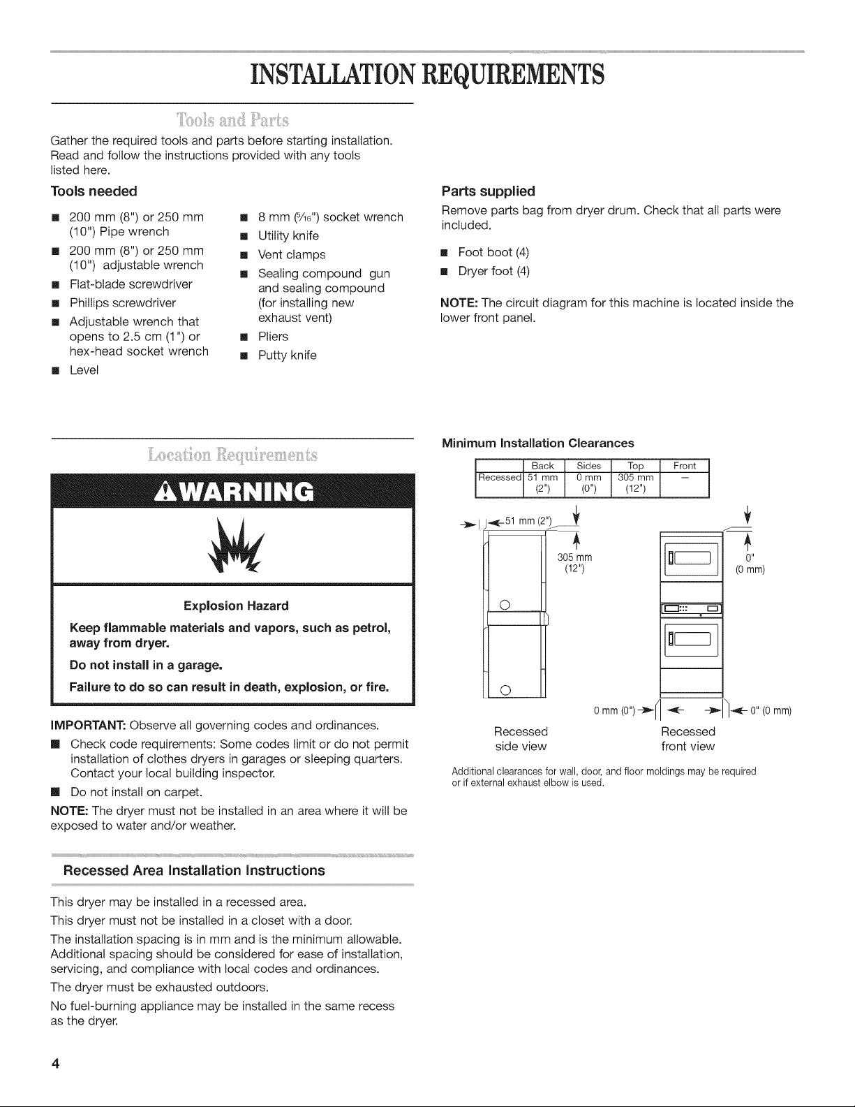
Minimum Installation Clearances
Back Sides Top { Front I
IRecessed{51 mm { 0mm [ 305mm [ -- {
(2") (0") (12")
-_1 j_-51 mm (2")_ _
3o5 mm
(12")
O
O
r-"l::: [z3
0 II
(0mm)
0 mm (0")--_l I_ _- ___l'-i__l,0" (0 mm)
Recessed Recessed
side view front view
Additional clearances for wall, door, and floor moldings may be required
or if external exhaust elbow is used.
Loading ...
Loading ...
Loading ...