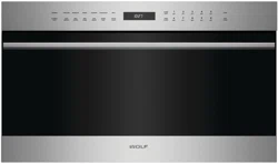
SPEED OVEN
INSTALLATION GUIDE
SPECIFICATIONS, INSTALLATION, AND MORE

2 | Wolf Customer Care 800.222.7820
SPEED OVEN
Contents
3 Speed Oven
4 Specications
7 Installation
7 Troubleshooting
Features and specications are subject to change at any
time without notice. Visit wolfappliance.com/specs for the
most up-to-date information.
Important Note
To ensure this product is installed and operated as safely
and efciently as possible, take note of the following types
of highlighted information throughout this guide:
IMPORTANT NOTE highlights information that is especially
important.
CAUTION indicates a situation where minor injury or product
damage may occur if instructions are not followed.
WARNING states a hazard that may cause serious injury or
death if precautions are not followed.
IMPORTANT NOTE: Throughout this guide, dimensions in
parentheses are millimeters unless otherwise specied.
IMPORTANT NOTE: Save these instructions for the local
electrical inspector.
wolfappliance.com | 3
SPEED OVEN
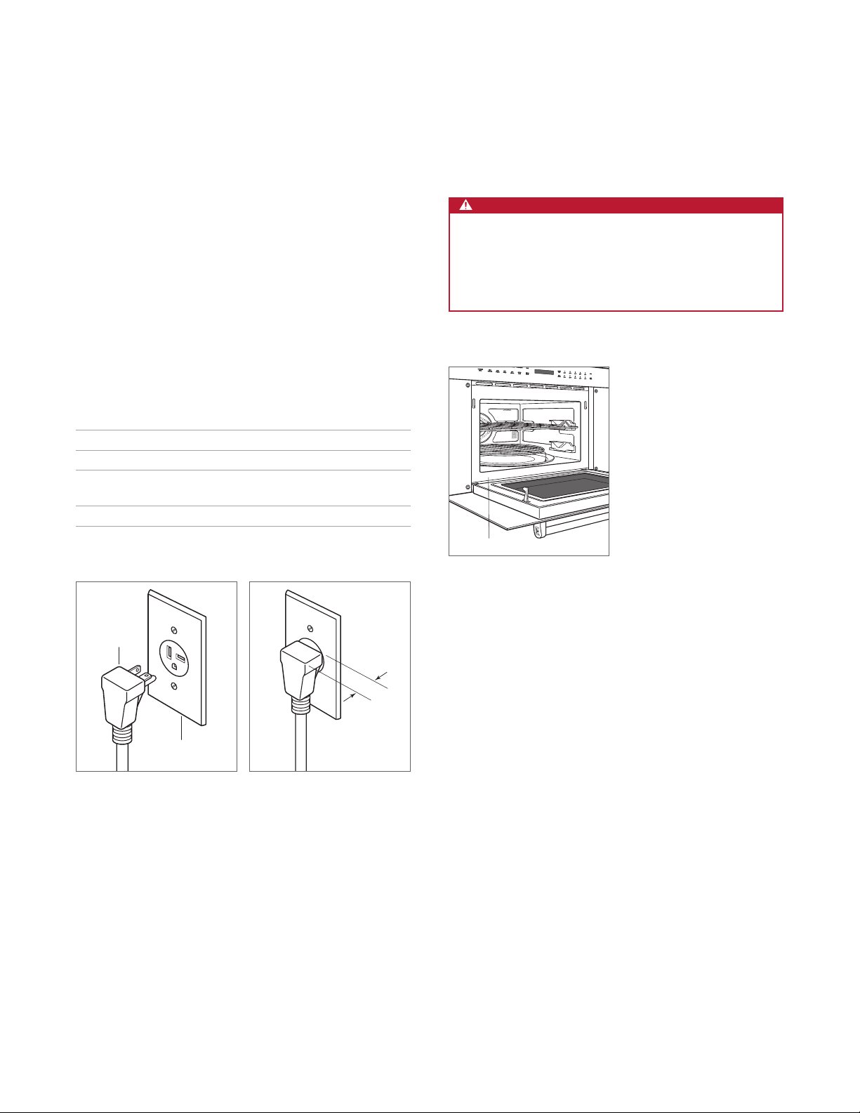
Product Information
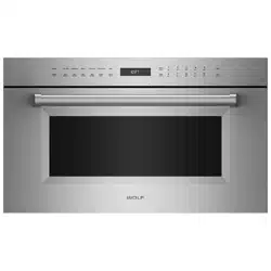
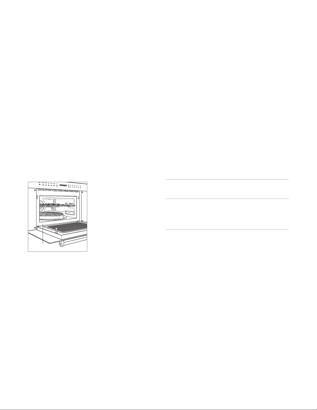
Important product information, including the model and
serial number, are listed on the product rating plate. The
rating plate is located on the lower left side of the front face
frame. The oven door must be open to view the rating plate.
Refer to the illustration below.
If service is necessary, contact Wolf Factory Certied
Service with the model and serial number. For the name of
the nearest Wolf Factory Certied Service or for questions
regarding the installation, visit the contact and support
section of our website, wolfappliance.com, or call Wolf
Customer Care at 800-222-7820.
Rating plate location
RATING PLATE
Installation Requirements
The speed oven can be installed in a standard or ush inset
application.
Finish the edges of the opening. They may be visible when
the door is open.
For standard installations, the face trim will overlap stiles
and rails. Refer to the chart below.
For ush inset installations, a minimum
1
/8" (3) reveal is
required on all sides. To ensure consistent reveals, each
corner of the opening must be exactly 90°.
If the speed oven is installed above or below a Wolf E series
oven in a ush inset application, a
1
/4" (6) reveal is required.
INSTALLATION REQUIREMENTS
BASE SUPPORT MIN
24" (610) Model 125 lb (57 kg)
30" (762) Model 125 lb (57 kg)
TRIM OVERLAP 24" MODEL 30" MODEL
Top
3
/16" (5)
3
/16" (5)
Bottom 0" (0) 0" (0)
Sides
11
/16" (18) 3
7
/8" (98)
4 | Wolf Customer Care 800.222.7820
Electrical Requirements
Installation must comply with all applicable electrical codes.
Locate the electrical supply as shown in the illustrations on
the following pages. The receptacle may also be located
in an adjacent cabinet within reach of the power cord. A
separate circuit, servicing only this appliance is required. A
ground fault circuit interrupter (GFCI) is not recommended
and may cause interruption of operation. Refer to the illus-
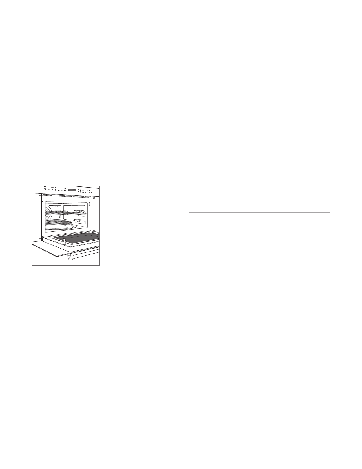
tration below for minimum power cord plug clearance.
ELECTRICAL REQUIREMENTS
Electrical Supply grounded, 240/208 VAC, 60 Hz
Service 15 amp dedicated circuit
Receptacle NEMA 6-20R grounding type
Power Cord 6'
(1.8 m)
WARNING
ELECTRICAL SHOCK HAZARD: Plug into a grounded
3-prong outlet. Do not remove the ground prong. Do
not use an adapter. Failure to follow these instructions
can result in electric shock, re, or death.
SPECIFICATIONS
NEMA
PLUG
GROUNDED
NEMA RECEPTACLE
1" (25)
MINIMUM
CORD
CLEARANCE
NEMA 6-20R receptacle
Power cord clearance
Rating plate location
RATING PLATE

wolfappliance.com | 5
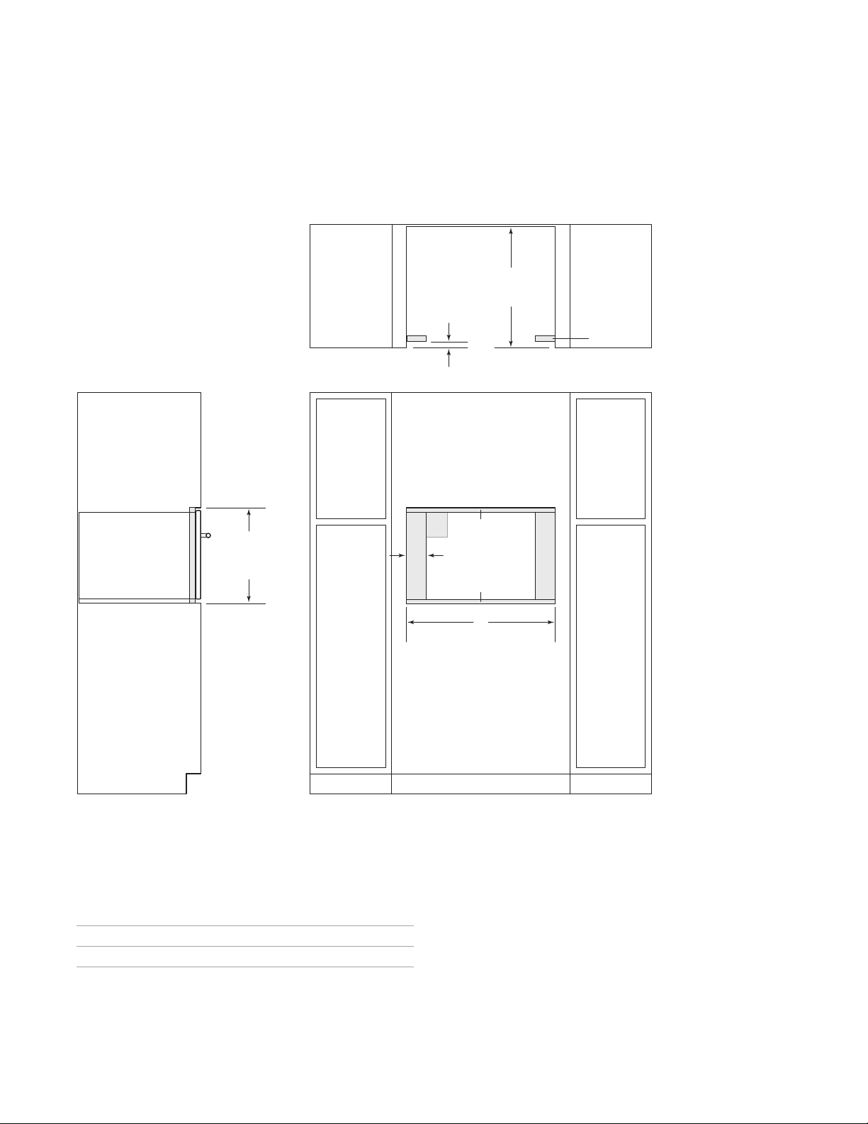
E
FRONT VIEW
SIDE
VIEW
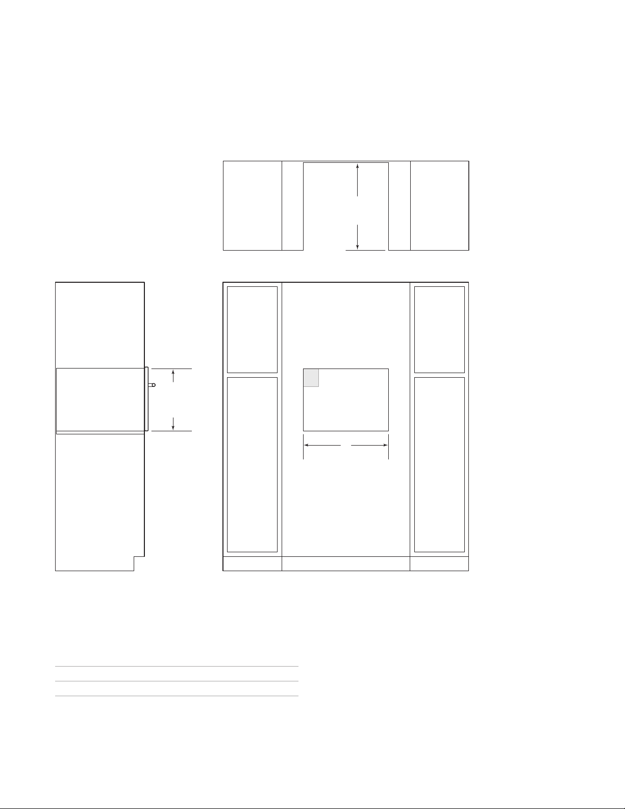
NOTE: 24"
(610) and 30" (762) models require the same opening dimensions.
17
11
/16"
(449)
OPENING
HEIGHT
23" (584)
OPENING
DEPTH
TOP VIEW
W
OPENING WIDTH
Speed Oven
STANDARD INSTALLATION
SPECIFICATIONS
OPENING WIDTH
W
24" Model 22
1
/8" (562)
30" Model 22
1
/8" (562)

6 | Wolf Customer Care 800.222.7820
E
W
FLUSH INSET WIDTH**
FRONT VIEW
SIDE
VIEW
24" (610)
FLUSH INSET
DEPTH
7
/
8
"
(22)
*W
ill be visible and should be finished to match cabinetry.
**
Dimension provides minimum reveals.
18
1
/8"
(460)
FLUSH INSET
HEIGHT**
5
/16"(8)
1
/8" (3)
A
TOP VIEW
FINISHED
CLEATS*
Speed Oven
FLUSH INSET INSTALLATION
SPECIFICATIONS
FLUSH INSET WIDTH
W A
24" Model 23
3
/4" (603)
13
/16" (21)
30" Model 30
1
/8" (765) 4" (102)
wolfappliance.com | 7
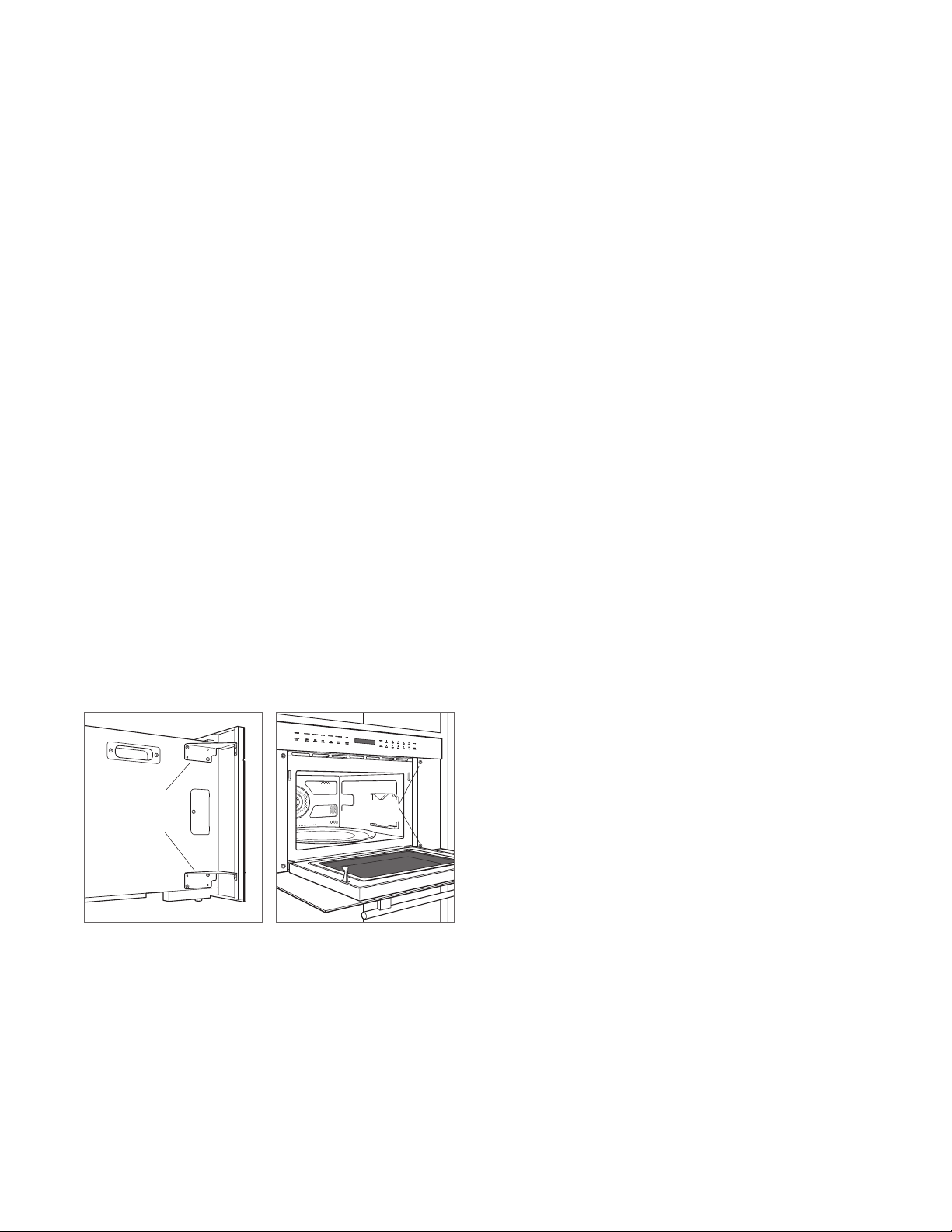
Installation
1 Turn off power to the electrical outlet.
2 Move the unit near the opening. Remove and recycle
packing materials.
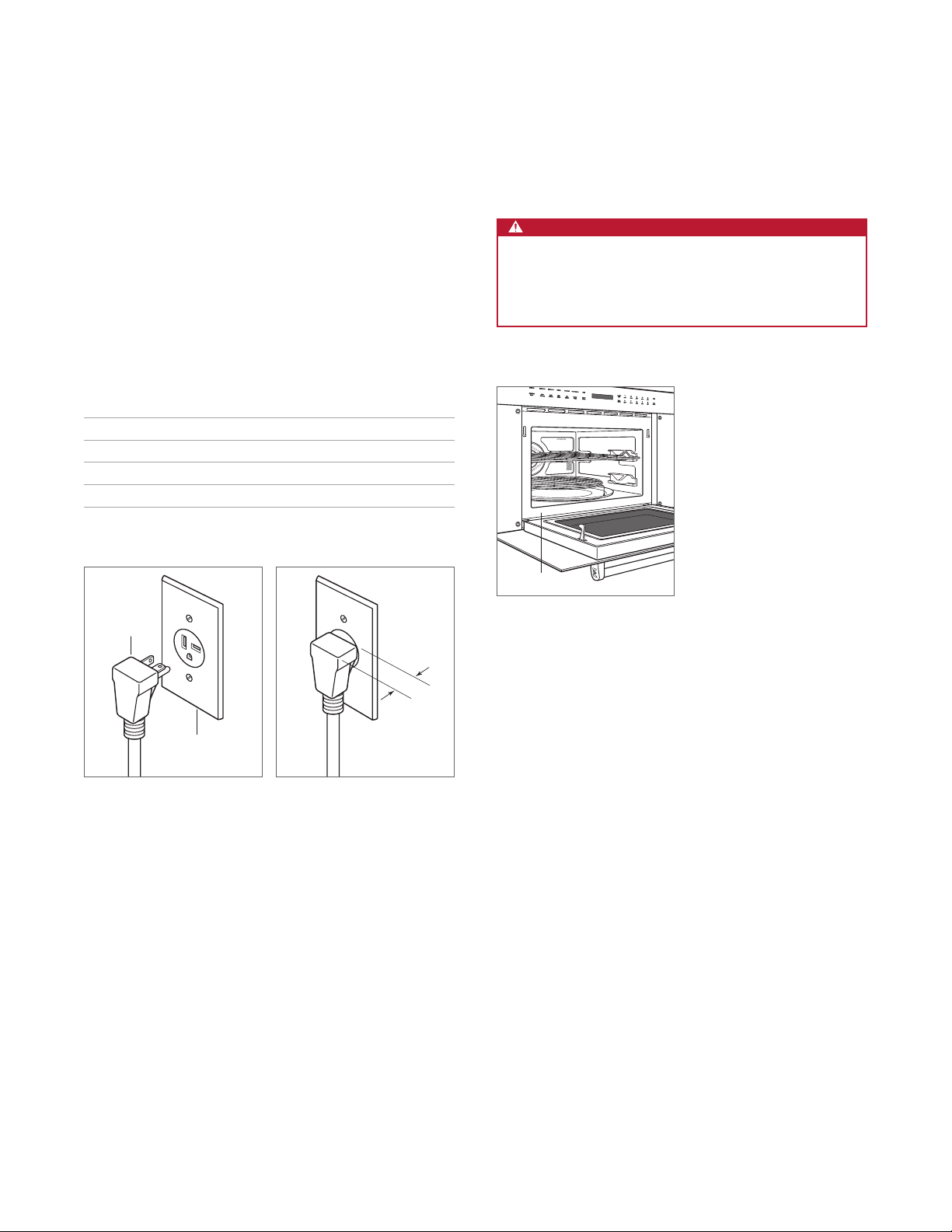
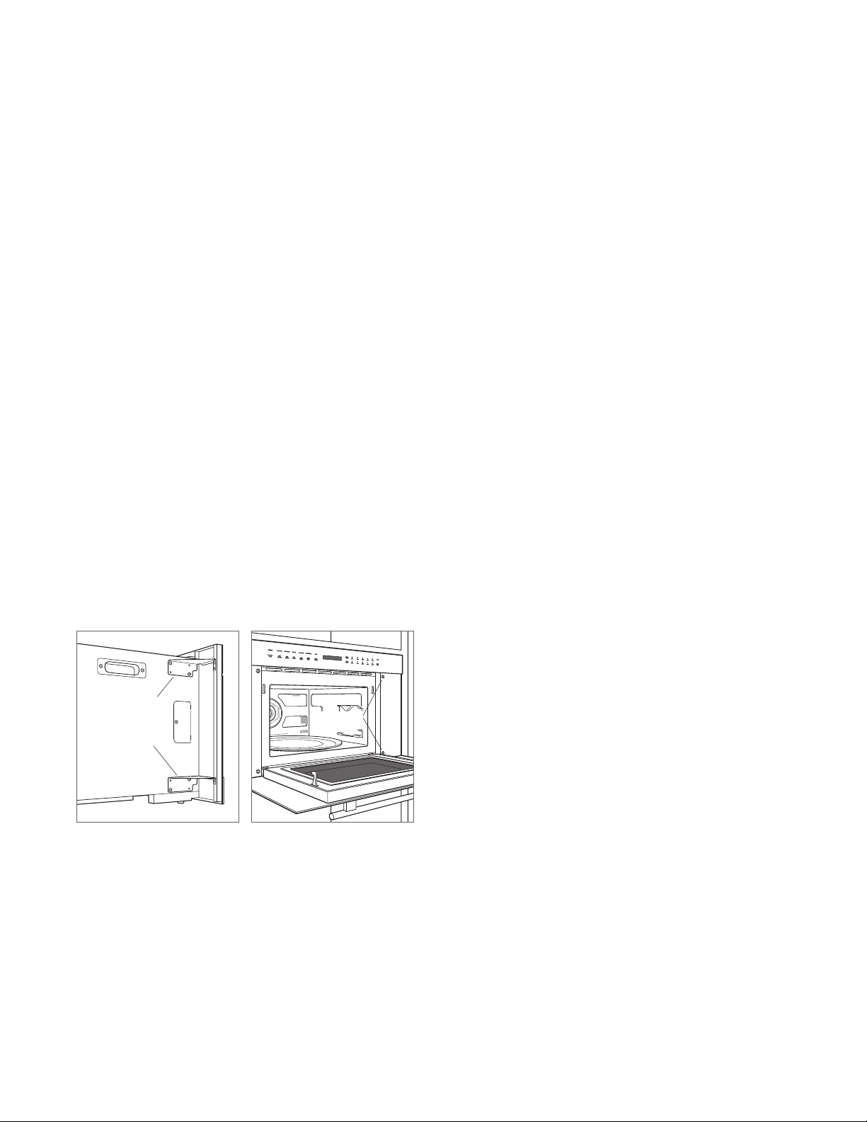
3 The 30" (762) model is shipped with two shipping
brackets located on each side, behind the front face.
Remove both brackets, then reinstall the screws. Refer
to the illustration below.
4 Plug the power cord into the grounded outlet.
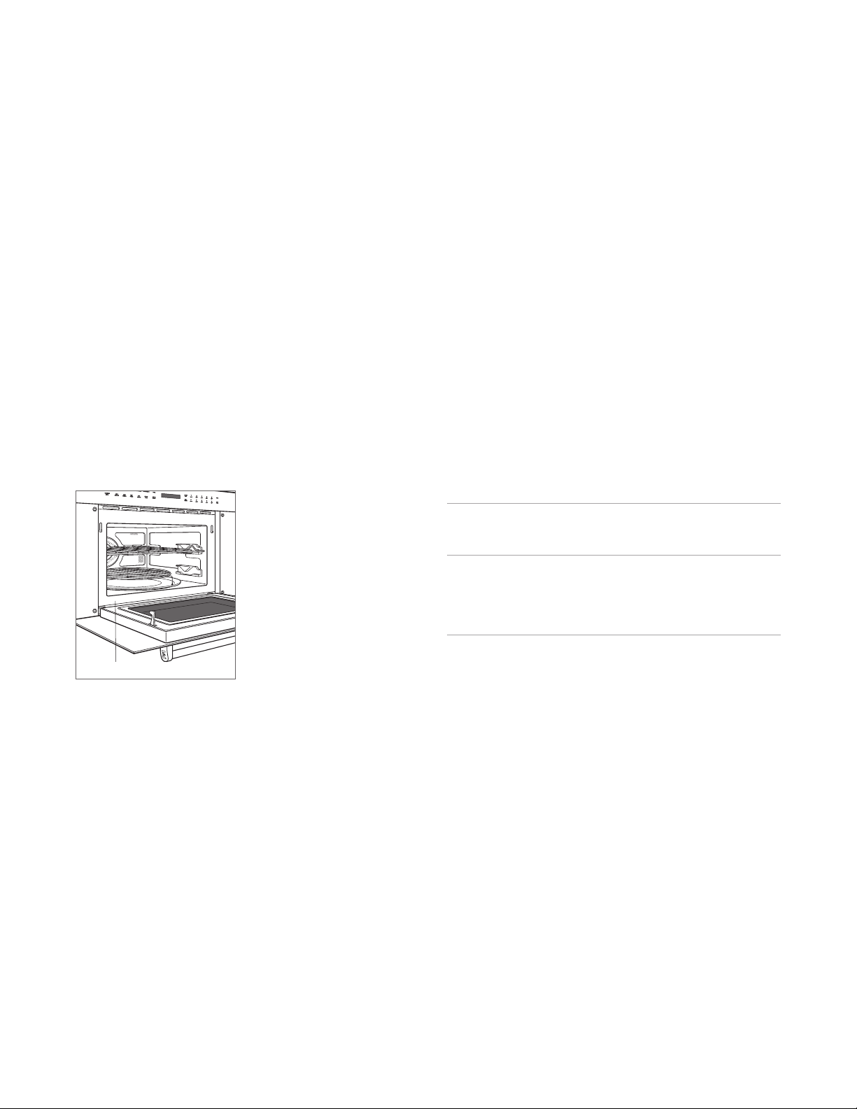
5 Position the oven in the opening and slide back until
the mounting ange is ush with the face of the cabinet.
Avoid pinching the power cord between the unit and
cabinet wall.
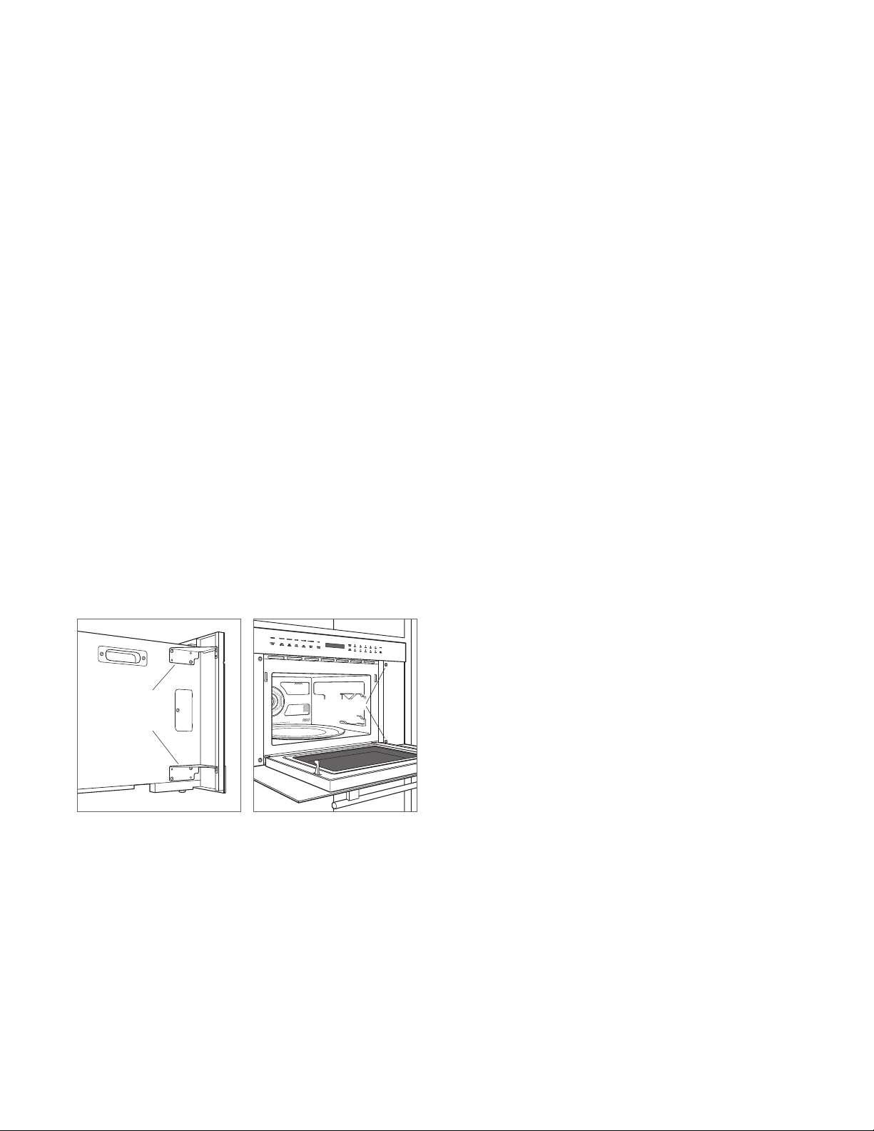
6 Open the door. Using the two holes on either side of the
mounting ange as a template, drill pilot holes into the
cabinet using a
1
/16" drill bit.
7 Mount the oven using the four screws provided. Refer to
the illustration below.
8 Turn power back on to the electrical outlet.
Troubleshooting
IMPORTANT NOTE: If the speed oven does not operate
properly, follow these troubleshooting steps:
• Verify electrical power is supplied to the oven.
• Verify proper electrical connections.
• If the oven does not operate properly, contact Wolf
Factory Certied Service. Do not attempt to repair the
oven. Wolf is not responsible for service required to
correct a faulty installation.
INSTALLATION
REMOVE
BRACKETS
THEN REINSTALL
SCREWS
MOUNTING
SCREWS
Shipping brackets
Mounting screws
Sub-Zero, Sub-Zero & Design, Sub-Zero & Snowake Design, Dual Refrigeration, The Living Kitchen, Great American Kitchens The Fine Art of Kitchen Design, Wolf, Wolf &
Design, Wolf Gourmet, W & Design, red colored knobs, Cove, and Cove & Design are registered trademarks and service marks of Sub-Zero Group, Inc. and its subsidiaries.
All other trademarks are property of their respective owners in the United States and other countries.

2 | Atención al cliente de Wolf 800.222.78200
HORNO DE VELOCIDAD
Contenido
3 Horno de velocidad
4 Especicaciones
7 Instalación
7 Resolución de problemas
Las características y especicaciones están sujetas a
cambios sin previo aviso. Visite wolfappliance.com/specs
para obtener la información más actualizada.
Aviso importante
Para garantizar que este producto se instale y opere de
la forma más segura y eciente posible, tome nota de los
siguientes tipos de información resaltada en este manual:
AVISO IMPORTANTE señala la información que es
especialmente importante.
PRECAUCIÓN indica una situación en la que se pueden
sufrir heridas leves o provocar daños al producto si no se
siguen las instrucciones.
ADVERTENCIA indica peligro de que se produzcan heridas
graves o incluso la muerte si no se siguen las precauciones.
AVISO IMPORTANTE: En toda esta guía, las dimensiones
entre paréntesis son milímetros, a menos que se especique
lo contrario.
AVISO IMPORTANTE: guarde estas instrucciones para el
inspector eléctrico local.
wolfappliance.com | 3
HORNO DE VELOCIDAD
Información del producto
La información importante del producto, incluidos el modelo
y el número de serie de la unidad, se encuentra en la placa
de datos del producto. La placa de datos se encuentra en el
lado inferior izquierdo del marco de la cara frontal. La puerta
del horno debe estar abierta para ver la placa de datos.
Consulte la siguiente ilustración.
Si es necesario realizar algún servicio, póngase en contacto
con el servicio certicado de fábrica de Wolf y tenga a mano
el modelo y el número de serie. Para obtener los datos del
Centro de Servicio Certicado de la fábrica de Wolf más
cercano o si tiene preguntas acerca de la instalación, visite
la sección de contacto y soporte técnico en nuestra página
de Internet wolfappliance.com; o bien, llame a la línea de
atención al cliente de Wolf al 800-222-7820.
Ubicación de la placa de datos
PLACA DE DATOS
Requisitos de instalación
El horno de velocidad se puede instalar en una aplicación
estándar o empotrable.
Dé el acabado a los bordes de la abertura. Pueden ser
visibles cuando la puerta está abierta.
Para instalaciones estándares, el ribete frontal se superpondrá
a los largueros y guías. Consulte la siguiente tabla.
Para las instalaciones empotrables se requiere un margen
mínimo de
1
/8" (3) en todos los lados. Para asegurar
márgenes consistentes, cada esquina de la abertura debe
tener exactamente 90º.
Si el horno de velocidad se instala por encima o por
debajo de un horno de la Serie E de Wolf en una aplicación
empotrable, se requiere un margen de
1
/4" (6).
REQUISITOS DE INSTALACIÓN
SOPORTE DE LA BASE MIN
Modelo de 24" (610) 125 lb (57 kg)
Modelo de 30" (762) 125 lb (57 kg)
SUPERPOSICIÓN DEL
RIBETE
MODELO DE 24"MODELO DE 30"
Parte superior
3
/16" (5)
3
/16" (5)
Parte inferior 0" (0) 0" (0)
Laterales
11
/16" (18) 3
7
/8" (98)

4 | Atención al cliente de Wolf 800.222.78200
Requisitos eléctricos
La instalación debe cumplir con todos los códigos
eléctricos vigentes.
Coloque el suministro eléctrico como se muestra en las
ilustraciones de las páginas siguientes. El receptáculo
también puede colocarse en un gabinete contiguo dentro
del alcance del cable de alimentación eléctrica. Se necesita
un circuito independiente que le suministre electricidad
únicamente a este electrodoméstico. No es recomendable
utilizar un circuito de fallos de conexión a tierra (GFCI,
por sus siglas en inglés) ya que puede interrumpir el
funcionamiento de la unidad. Consulte la ilustración
siguiente para conocer el espacio mínimo del enchufe del
cable de corriente.
REQUISITOS ELÉCTRICOS
Suministro eléctrico Con conexión a tierra, 240/208 VCA, 60 Hz
Servicio Circuito dedicado de 15 amperes
Receptáculo Tipo de conexión a tierra NEMA 6-20R
Cable de alimentación
eléctrica
6'
(1.8 m)
ADVERTENCIA
PELIGRO DE DESCARGA ELÉCTRICA Enchufe en
tomacorriente de 3 puntos con conexión a tierra.
No retire la clavija de conexión a tierra. No utilice un
adaptador. No cumplir con estas instrucciones puede
producir una descarga eléctrica, incendio o muerte.
ESPECIFICACIONES
ENCHUFE
NEMA
RECEPTÁCULO NEMA
CON CONEXIÓN
A TIERRA
1" (25)
ESPACIO LIBRE
MÍNIMO PARA
EL CABLE
Receptáculo NEMA 6-20R
Espacio libre para el cable
Ubicación de la placa de datos
PLACA DE DATOS
wolfappliance.com | 5
E
VISTA FRONTAL
VIST
A LATERAL
NOTA: Los modelos de 24" (610) y 30" (762) requieren las mismas dimensiones de abertura.
17
11
/16"
(449)
ALTURA DE
LA ABERTURA
23"
(584)
PROFUNDIDAD
DE LA ABERTURA
VISTA SUPERIOR
W
ANCHO DE LA ABERTURA
Horno de velocidad
INSTALACIÓN ESTÁNDAR
ESPECIFICACIONES
ANCHO DE LA ABERTURA
W
Modelo de 24" 22
1
/8" (562)
Modelo de 30" 22
1
/8" (562)

6 | Atención al cliente de Wolf 800.222.78200
E
W
ANCHO DE LA
INSTALACIÓN EMPOTRABLE**
VISTA FRONTAL
VIST
A LATERAL
24" (610)
PROFUNDIDAD DE
LA INSTALACIÓN
EMPOTRABLE
7
/8" (22)
* Será visible y debe tener un acabado que haga juego con los gabinetes.
**La dimensión especifica los márgenes mínimos.
18
1
/8"
(460)
ALTURA DE
LA INSTALACIÓN
EMPOTRABLE**
5
/16"(8)
1
/8" (3)
A
VISTA SUPERIOR
CORNAMUSAS
TERMINADAS*
Horno de velocidad
INSTALACIÓN EMPOTRABLE
ESPECIFICACIONES
ANCHO DE LA INSTALACIÓN
EMPOTRABLE
W
A
Modelo de 24" 23
3
/4" (603)
13
/16" (21)
Modelo de 30" 30
1
/8" (765) 4" (102)
wolfappliance.com | 7
Instalación
1 Desconecte la alimentación del tomacorriente eléctrico.
2 Mueva la unidad cerca de la abertura. Retire y recicle los
materiales de embalaje.
3 El modelo de 30" (762) se entrega con dos soportes
de embalaje que se encuentran a cada lado detrás
de la cara frontal. Retire los dos soportes e instale los
tornillos. Consulte la siguiente ilustración.
4 Conecte el cable de alimentación eléctrica en un
tomacorriente con conexión a tierra.
5 Coloque el horno en la abertura y deslícelo hacia atrás
hasta que el reborde para montaje se encuentre a ras con el
frente del gabinete. Evite pellizcar el cable de alimentación
eléctrica entre la unidad y la pared del gabinete.
6 Abra la puerta. Utilice los dos oricios ubicados a cada
lado del reborde para montaje como plantilla y perfore
los oricios guía en el gabinete con una broca de
1
/16".
7 Monte el horno usando los cuatro tornillos
proporcionados. Consulte la siguiente ilustración.
8 Conecte la alimentación del tomacorriente eléctrico.
Solución de problemas
AVISO IMPORTANTE: Si el horno de velocidad no funciona
correctamente, siga estos pasos para resolver los problemas:
• Compruebe que el horno tiene corriente eléctrica.
• Compruebe que las conexiones eléctricas estén correctas.
• Si el horno no funciona correctamente, póngase en
contacto con el centro de servicio autorizado de Wolf.
No intente reparar el horno. Wolf no es responsable del
servicio necesario para corregir una instalación defectuosa.
INSTALACIÓN
RETIRE LOS
SOPORTES
Y VUELVA
A INSTALAR
LOS TORNILLOS
TORNILLOS
DE MONTAJE
Soportes de embalaje
Tornillos de montaje
Sub-Zero, Sub-Zero & Design, Sub-Zero & Snowake Design, Dual Refrigeration, The Living Kitchen, Great American Kitchens The Fine Art of Kitchen Design, Wolf, Wolf & Design,
Wolf Gourmet, W & Design, red colored knobs (perillas de color rojo), Cove y Cove & Design son marcas registradas y marcas de servicio de Sub-Zero Group, Inc. y sus liales.
Todas las demás marcas registradas son propiedad de sus dueños respectivos en Estados Unidos y otros países.

2 | Service à la clientèle de Wolf 800.222.7820
FOUR À CUISSON RAPIDE
Table des matières
3 Four à cuisson rapide
4 Spécications
7 Installation
7 Dépannage
Les caractéristiques et les spécications peuvent être
modiées en tout temps sans préavis. Visitez wolfappliance.
com/specs pour obtenir les renseignements les plus récents.
Remarque importante
Pour s’assurer que ce produit est installé et utilisé en toute
sécurité et aussi efcacement que possible, prenez note des
types de renseignement mis en évidence tout au long de
ce guide :
REMARQUE IMPORTANTE met en évidence des
renseignements qui sont particulièrement importants.
MISE EN GARDE indique une situation où une blessure
mineure ou des dommages au produit peuvent se produire
si les directives ne sont pas respectées.
AVERTISSEMENT décrit un danger qui peut causer une
blessure grave ou la mort si les précautions ne sont
pas respectées.
REMARQUE IMPORTANTE : Tout au long de ce guide, les
dimensions entre parenthèses sont en millimètres à moins
d’indication contraire.
REMARQUE IMPORTANTE : Conservez ces directives pour
l’inspecteur en électricité local.
wolfappliance.com | 3
FOUR À CUISSON RAPIDE
Renseignements sur le produit
Des renseignements importants sur le produit, y compris les
numéros de modèle et de série, se trouvent sur la plaque
signalétique du produit. La plaque signalétique est située
sur le côté gauche du cadre du panneau avant. La porte
du four doit être ouverte pour voir la plaque signalétique.
Reportez-vous à l’illustration ci-dessous.
Si vous avez besoin de service, communiquez avec le
service Wolf certié par l’usine avec les numéros de modèle
et de série. Pour obtenir le nom du centre de service Wolf
certié par l’usine le plus près de chez vous ou si vous
avez des questions concernant l’installation, consultez
la section Contact et assistance de notre site Web,
www.wolfappliance.com ou appelez le service à la clientèle
de Wolf au 800-222-7820.
Emplacement de la plaque
signalétique
PLAQUE SIGNALÉTIQUE
Exigences d’installation
Le four à cuisson rapide peut être installé dans une
application standard ou à afeurement.
Finissez les rebords de l’ouverture. Ils peuvent être visibles
lorsque la porte est ouverte.
Pour les installations standards, la garniture frontale
chevauchera les montants et les rails. Reportez-vous au
tableau ci-dessous.
Pour les installations à afeurement, un jeu minimum
de
1
/8po (3) est requis de tous les côtés. Pour assurer des
jeux uniformes, chaque coin de l’ouverture doit mesurer
exactement 90 degrés.
Si le four à cuisson rapide est installé au-dessus ou sous un
four Wolf de la série E dans une application à afeurement,
un jeu de
1
/4 po (6) est requis.
EXIGENCES D’INSTALLATION
SUPPORT DE BASE MIN.
Modèle de 24po (610) 125 lb (57 kg)
Modèle de 30po (762) 125 lb (57 kg)
CHEVAUCHEMENT DE
LA GARNITURE
MODÈLE DE
24 PO
MODÈLE DE
30 PO
Dessus
3
/16po (5)
3
/16po (5)
Bas 0po (0) 0po (0)
Côtés
11
/16po (18) 3
7
/8po (98)
4 | Service à la clientèle de Wolf 800.222.7820
Exigences électriques
L’installation doit se conformer à tous les codes électriques
applicables.
Repérez l’alimentation électrique, comme il est montré
dans les illustrations aux pages suivantes. La prise peut
aussi se trouver dans une armoire adjacente à la portée
du cordon d’alimentation. Un circuit séparé servant
uniquement cet appareil est requis. Un disjoncteur de fuite
de terre (GFCI) n’est pas recommandé et peut interrompre
le fonctionnement. Reportez-vous à l’illustration ci-dessous
pour connaître le dégagement minimum requis pour la che
du cordon d’alimentation.
EXIGENCES ÉLECTRIQUES
Alimentation électrique mise à la terre, 240/208 volts CA, 60 Hz
Service circuit dédié de 15 ampères
Prise prise NEMA 6-20R de type mise
à la terre
Cordon d’alimentation 6 pi
(1,8 m)
AVERTISSEMENT
DANGER DE CHOC ÉLECTRIQUE : branchez dans une
prise à trois broches mise à la terre. Ne retirez pas la
broche de mise à la terre. N’utilisez pas un adaptateur.
Le non-respect de ces directives peut provoquer un
incendie, un choc électrique, ou même, la mort.
SPÉCIFICATIONS
FICHE
NEMA
PRISE NEMA
MISE À LA TERRE
1 po
(25)
DÉGAGEMENT
MINIMUM
DU CORDON
Prise NEMA 6-20R
Dégagement du cordon
d’alimentation
Emplacement de la plaque
signalétique
PLAQUE SIGNALÉTIQUE

wolfappliance.com | 5
E
VUE DE FACE
VUE DE PR
OFIL
REMARQUE : Les modèles de 24 po (610 mm) et 30 po (762 mm) nécessitent les mêmes dimensions d’ouverture.
17
11
/16 po
(449)
HAUTEUR DE
L’OUVERTURE
23 po (584)
PROFONDEUR
DE L’OUVERTURE
VUE DE DESSUS
W
LARGEUR DE
L’OUVERTURE
Four à cuisson rapide
INSTALLATION STANDARD
SPÉCIFICATIONS
LARGEUR DE L’OUVERTURE
W
Modèle de 24 po 22
1
/8po (562)
Modèle de 30 po 22
1
/8po (562)
6 | Service à la clientèle de Wolf 800.222.7820
E
W
LARGEUR DE
L’AFFLEUREMENT**
VUE DE FACE
VUE DE PR
OFIL
24 po (610)
PROFONDEUR DE
L’AFFLEUREMENT
7
/
8
po
(22)
*Seront visibles et doivent avoir une finition correspondant à l’ébénisterie
.
**La dimension fournit des jeux minimums.
18
1
/8 po
(460)
HAUTEUR DE
L’AFFLEUREMENT**
5
/16 po (8)
1
/8 po (3)
A
VUE DE DESSUS
TAQUETS
FINIS*
Four à cuisson rapide
INSTALLATION À AFFLEUREMENT
SPÉCIFICATIONS
LARGEUR DE L’AFFLEUREMENT
W A
Modèle de 24 po 23
3
/4po (603)
13
/16po (21)
Modèle de 30 po 30
1
/8po (765) 4po (102)
wolfappliance.com | 7
Installation
1 Coupez le courant vers la prise électrique.
2 Déplacez l’unité près de l’ouverture. Retirez et recyclez
les matériaux d’emballage.
3 Le modèle de 30po (762) est expédié avec des supports
d’expédition situés de chaque côté, derrière la face
frontale. Retirez les deux supports, puis réinstallez les
vis. Reportez-vous à l’illustration ci-dessous.
4 Branchez le cordon d’alimentation dans la prise mise à
la terre.
5 Placez le four dans l’ouverture et poussez-le vers
l’arrière jusqu’à ce que la bride de montage soit à égalité
avec la face de l’armoire. Évitez de coincer le cordon
d’alimentation entre l’unité et le mur de l’armoire.
6 Ouvrez la porte. En utilisant les deux trous de chaque
côté de la bride de montage comme gabarit, percez
des avant-trous dans l’armoire au moyen d’une mèche
de
1
/16po.
7 Installez le four avec les quatre vis fournies. Reportez-
vous à l’illustration ci-dessous.
8 Rétablissez le courant au niveau de la prise de courant.
Dépannage
REMARQUE IMPORTANTE : Si le four à cuisson rapide
ne fonctionne pas correctement, suivez les étapes de
dépannage suivantes:
• Vériez l’alimentation électrique du four.
• Vériez les connexions électriques.
• Si le four ne fonctionne pas correctement, communiquez
avec le centre de service Wolf certié par l’usine. Ne tentez
pas de réparer le four. Wolf n’est pas responsable du
service requis pour corriger une installation défectueuse.
INSTALLATION
RETIREZ LES
SUPPORTS, PUIS
RÉINSTALLEZ
LES VIS
VIS DE
MONTAGE
Supports d’expédition
Vis de montage
Sub-Zero, Sub-Zero & Design, Sub-Zero & Snowake Design, Dual Refrigeration, The Living Kitchen, Great American Kitchens The Fine Art of Kitchen Design, Wolf, Wolf &
Design, Wolf Gourmet, W & Design, les boutons de couleur rouge, Cove et Cove & Design sont des marques déposées et de service de Sub-Zero Group, Inc. et ses liales.
Toutes les autres marques de commerce appartiennent à leurs propriétaires respectifs aux États-Unis et dans d’autres pays.

WOLF APPLIANCE, INC. P.O. BOX 44848 MADISON, WI 53744 WOLFAPPLIANCE.COM 800.222.7820
9021482 REV-A 12/2018