Operators nuai
ICRAFTSMAN°I
Permanently Lubricated
Tank Mounted
AI CO
Model No.
9.16724q
= Safety Guidelines
= Assembly
• Operation
= Maintenance
= Service and Adjustments
• Troubleshooting
• Espahol
CAUTION" Read the Safety Guidelines
and All Instructions Carefully Before
Operating.
Sears, Roebuck and Co., Hoffman Estates, IL 60179 U.S.A.
Visit our Craftsman website: www.sears.com/craftsman
D21996 Rev. 1 7/30/01
WARRANTY ............................. 2
SAFETY GUIDELINES .................... 3-6
GLOSSARY .............................. 7
ACCESSORIES .......................... 7
ASSEMBLY ............................ 7-8
Contents of Carton ..................... 7
Tool Required for Assembly ............... 7
Installing Handle, Wheels,
and Molded Foot Bumpers ............... 7
iNSTALLATION ........................... 9
Location of Air Compressor ............... 9
Grounding Instructions .................. 9
Extension Cords ....................... 9
Voltage and Circuit Protection ............. 9
OPERATING PROCEDURES ............. 10-11
Know Your Air Compressor .............. 10
Description of Operation ................ 10
How to Stop ......................... 11
Before Starting
Break-in Procedure ................. 11
Before Each Start-Up .................. 11
How to Start ......................... 11
MAINTENANCE ......................... 12 .
Customer Responsibilities .................. 12
To Check Safety Valve .................. 12
To Drain Tank ........................ 12
SERVICE AND ADJUSTMENTS ............. 13
To Replace or Clean Check Valve ......... 13
To Replace Regulator .................. 13
STORAGE .............................. 14
TROUBLESHOOTING GUIDE ............ 15-16
ESPANOL ........................... 17-33
HOW TO ORDER REPAIR PARTS .... Back Cover
FULL ONE YEAR WARRANTY
AIR COMPRESSOR
If this air compressor fails due to a defect in material or workmanship within one year from the date of
purchase, RETURN IT TO THE NEAREST SEARS REPAIR CENTER THROUGHOUT THE UNITED STATES
AND SEARS WILL REPAIR IT, FREE OF CHARGE. If purchased from Orchard Supply Hardware, return to
the nearest Orchard Store and Orchard will repair it, free of charge.
If this air compressor is used for commercial or rental purposes, the warranty will apply for ninety days
from the date of purchase.
This warranty gives you specific legal rights and you may have other rights which vary from state to state.
Sears, Roebuck and Co., Dept.. 817WA, Hoffman Estates, fl 60179
D21996 2-Eng
SAFETY and PREVENTING EQUIPMENT PROBLEMS. To help you recognize this information, we use the symbols
below. Please read the manual and pay attention to these sections.
Indicates an imminently hazardous
situation which, if not avoided, will
result in death or serious iniury.
Indicates a potentially hazardous sit-
uation which, if not avoided, could
result in death or serious iniury.
Indicates a potentially hazardous
situation which, if not avoided,
result in minor or moderate iniury.
Used without the safety alert sym-
bol indicates a potentially haz-
ardous situation which, if not avoided, may result in
property damacLe.
O SAVE THESE iNSTRUCTiONS _l
IMPROPER OPERATION OR MAINTENANCE OF THIS PRODUCT COULD RESULT IN SERIOUS INJURY
AND PROPERTY DAMAGE. READ AND UNDERSTAND ALL WARNINGS AND OPERATING INSTRUC-
TIONS BEFORE USING THIS EQUIPMENT.
RISK OF EXPLOSION OR FIRE
WHAT CAN HAPPEN
iT IS NORMAL FOR ELECTRICAL CONTACTS WITHIN
THE MOTOR AND PRESSURE SWITCH TO SPARK.
iF ELECTRICAL SPARKS FROM COMPRESSOR COME
iNTO CONTACT WiTH FLAMMABLE VAPORS, THEY
MAY iGNiTE, CAUSING FiRE OR EXPLOSION.
RESTRICTING ANY OF THE COMPRESSOR VENTILA-
TION OPENINGS WILL CAUSE SERIOUS OVERHEATING
AND COULD CAUSE FIRE.
UNATTENDED OPERATION OF THIS PRODUCT COULD
RESULT iN PERSONAL INJURY OR PROPERTY DAM-
AGE. TO REDUCE THE RISK OF FIRE, DO NOT ALLOW
THE COMPRESSOR TO OPERATE UNATTENDED.
HOW TO PREVENT IT
ALWAYS OPERATE THE COMPRESSOR iN A WELL VEN-
TILATED AREA FREE OF COMBUSTIBLE MATERIALS,
GASOLINE OR SOLVENT VAPORS.
IF SPRAYING FLAMMABLE MATERIALS, LOCATE COM-
PRESSOR AT LEAST 20 FEET AWAY FROM SPRAY
AREA. AN ADDITIONAL LENGTH OF HOSE MAY BE
REQUIRED.
STORE FLAMMABLE MATERIALS iN A SECURE LOCA-
TION AWAY FROM COMPRESSOR.
NEVER PLACE OBJECTS AGAINST OR ON TOP OF
COMPRESSOR. OPERATE COMPRESSOR IN AN OPEN
AREA AT LEAST 12 iNCHES AWAY FROM ANY WALL
OR OBSTRUCTION THAT WOULD RESTRICT THE FLOW
OF FRESH AIR TO THE VENTILATION OPENINGS.
OPERATE COMPRESSOR IN A CLEAN, DRY, WELL VENTI-
LATED AREA. DO NOT OPERATE UNiT iNDOORS OR iN
ANY CONFINED AREA.
ALWAYS REMAIN IN ATTENDANCE WiTH THE PROD=
UCT WHEN IT IS OPERATING.
ALWAYS DISCONNECT ELECTRICAL POWER BY MOV-
ING PRESSURE SWITCH LEVER TO THE OFF POSITION
AND DRAIN TANK DAILY OR AFTER EACH USE.
3-Eng D21996
RiSK OF BURSTING
AiR TANK: THE FOLLOWING CONDITIONS COULD LEAD TO A WEAKENING OF THE TANK, AND
RESULT JN A VIOLENT TANK EXPLOSION AND COULD CAUSE PROPERTY DAMAGE OR SERIOUS
iNJURY.
WHAT CAN HAPPEN HOW TO PREVENT iT
t. FAILURE TO PROPERLY DRAIN CONDENSED
WATER FROM THE TANK, CAUSING RUST
AND THiNNiNG OF THE STEEL TANK.
2. MODiFiCATiONS OR ATTEMPTED REPAIRS TO THE
TANK.
3. UNAUTHORIZED MODiFiCATiONS TO THE
UNLOADER VALVE, SAFETY VALVE, OR ANY
OTHER COMPONENTS WHICH CONTROL TANK
PRESSURE.
4. EXCESSIVE ViBRATiON CAN WEAKEN THE AiR
TANK AND CAUSE RUPTURE OR EXPLOSION.
ATTACHMENTS & ACCESSORIES:
EXCEEDING THE PRESSURE RATING OF AiR TOOLS,
SPRAY GUNS, AIR OPERATED ACCESSORIES, TIRES AND
OTHER INFLATABLES CAN CAUSE THEM TO EXPLODE
OR FLY APART, AND COULD RESULT IN SERIOUS INJURY.
DRAIN TANK DAILY OR AFTER EACH USE. IF TANK
DEVELOPS A LEAK, REPLACE IT IMMEDIATELY WITH A
NEW TANK OR REPLACE THE ENTIRE COMPRESSOR.
NEVER DRILL INTO, WELD, OR MAKE ANY MODIFICA-
TIONS TO THE TANK OR ITS ATTACHMENTS.
THE TANK IS DESIGNED TO WITHSTAND SPECIFIC OPER-
ATING PRESSURES. NEVER MAKE ADJUSTMENTS OR
PARTS SUBSTiTUTiONS TO ALTER THE FACTORY SET
OPERATING PRESSURES.
FOR ESSENTIAL CONTROL OF AIR PRESSURE,YOU
MUST iNSTALL A PRESSURE REGULATOR AND PRES=
SURE GAUGE TO THE AiR OUTLET (iF NOT EQUIPPED)
OF YOUR COMPRESSOR. FOLLOW THE EQUIPMENT
MANUFACTURERS RECOMMENDATION AND NEVER
EXCEED THE MAXIMUM ALLOWABLE PRESSURE RATING
OF ATTACHMENTS. NEVER USE COMPRESSOR TO
iNFLATE SMALL LOW-PRESSURE OBJECTS SUCH AS
CHILDREN'S TOYS, FOOTBALLS, BASKETBALLS, ETC.
RiSK FROM FLYING OBJECTS
WHAT CAN HAPPEN
THE COMPRESSED AiR STREAM CAN CAUSE SOFT TIS-
SUE DAMAGE TO EXPOSED SKIN AND CAN PROPEL
DIRT, CHIPS, LOOSE PARTICLES AND SMALL OBJECTS
AT HiGH SPEED, RESULTING IN PROPERTY DAMAGE OR
PERSONAL INJURY.
HOW TO PREVENT iT
ALWAYS WEAR ANSi Z87.1 APPROVED SAFETY GLASS-
ES WiTH SiDE SHIELDS WHEN USING THE COMPRES-
SOR.
NEVER POINT ANY NOZZLE OR SPRAYER TOWARD
ANY PART OF THE BODY OR AT OTHER PEOPLE OR
ANIMALS.
ALWAYS TURN THE COMPRESSOR OFF AND BLEED
PRESSURE FROM THE AIR HOSE AND TANK BEFORE
ATTEMPTING MAINTENANCE, ATTACHING TOOLS OR
ACCESSORIES.
D21996 4-Eng
RiSK OF ELECTRICAL SHOCK
WHAT CAN HAPPEN
YOUR AiR COMPRESSOR IS POWERED BY ELECTRICI=
TY. LIKE ANY OTHER ELECTRICALLY POWERED DEVICE,
iF iT iS NOT USED PROPERLY iT MAY CAUSE ELECTRIC
SHOCK.
REPAIRS ATTEMPTED BY UNQUALiFiED PERSONNEL
CAN RESULT iN SERIOUS iNJURY OR DEATH BY ELEC=
TROCUTION.
ELECTRICAL GROUNDING: FAILURE TO PROVIDE ADE=
QUATE GROUNDING TO THiS PRODUCT COULD
RESULT iN SERIOUS iNJURY OR DEATH FROM ELEC=
TROCUTION. SEE GROUNDING INSTRUCTIONS.
HOW TO PREVENT iT
NEVER OPERATE THE COMPRESSOR OUTDOORS WHEN
iT iS RAINING OR IN WET CONDITIONS.
NEVER OPERATE COMPRESSOR WiTH PROTECTIVE
COVERS REMOVED OR DAMAGED.
ANY ELECTRICAL WiRiNG OR REPAIRS REQUIRED ON
THIS PRODUCT SHOULD BE PERFORMED BY AUTHO=
RIZED SERVICE CENTER PERSONNEL iN ACCORDANCE
WITH NATIONAL AND LOCAL ELECTRICAL CODES.
MAKE CERTAIN THAT THE ELECTRICAL CiRCUiT TO
WHICH THE COMPRESSOR IS CONNECTED PROVIDES
PROPER ELECTRICAL GROUNDING, CORRECT VOLT=
AGE AND ADEQUATE FUSE PROTECTION.
RiSK TO BREATHING
WHAT CAN HAPPEN HOW TO PREVENT iT
THE COMPRESSED AiR DIRECTLY FROM YOUR COM-
PRESSOR iS NOT SAFE FOR BREATHING. THE AiR
STREAM MAY CONTAIN CARBON MONOXIDE, TOXIC
VAPORS, OR SOLID PARTICLES FROM THE TANK.
BREATHING THESE CONTAMINANTS CAN CAUSE
SERIOUS iNJURY OR DEATH.
SPRAYED MATERIALS SUCH AS PAINT, PAINT SOL-
VENTS, PAINT REMOVER, INSECTICIDES, WEED
KILLERS, CONTAIN HARMFUL VAPORS AND POISONS.
AiR OBTAINED DIRECTLY FROM THE COMPRESSOR
SHOULD NEVER BE USED TO SUPPLY AiR FOR HUMAN
CONSUMPTION. IN ORDER TO USE AIR PRODUCED BY
THIS COMPRESSOR FOR BREATHING, SUITABLE FiL-
TERS AND IN-LINE SAFETY EQUIPMENT MUST BE
PROPERLY iNSTALLED. IN-LINE FILTERS AND SAFETY
EQUIPMENT USED IN CONJUNCTION WITH THE COM-
PRESSOR MUST BE CAPABLE OF TREATING AiR TO ALL
APPLICABLE LOCAL AND FEDERAL CODES PRIOR TO
HUMAN CONSUMPTION.
WORK iN AN AREA WITH GOOD CROSS=VENTILATION.
READ AND FOLLOW THE SAFETY INSTRUCTIONS PRO-
VIDED ON THE LABEL OR SAFETY DATA SHEETS FOR
THE MATERIAL YOU ARE SPRAYING. USE A
NIOSH/MSHA APPROVED RESPIRATOR DESIGNED FOR
USE WITH YOUR SPECIFIC APPLICATION.
5-Eng D21996
RISK OF BURNS
WHAT CAN HAPPEN
TOUCHING EXPOSED METAL SUCH AS THE COMPRES-
SOR HEAD OR OUTLET TUBES, CAN RESULT IN
SERIOUS BURNS.
HOW TO PREVENT iT
NEVER TOUCH ANY EXPOSED METAL PARTS ON
COMPRESSOR DURING OR IMMEDIATELY AFTER OPER-
ATION. COMPRESSOR WILL REMAIN HOT FOR SEVERAL
MINUTES AFTER OPERATION.
DO NOT REACH AROUND PROTECTIVE SHROUDS OR
ATTEMPT MAINTENANCE UNTIL UNIT HAS BEEN
ALLOWED TO COOL.
RiSK FROM MOVING PARTS
WHAT CAN HAPPEN HOW TO PREVENT IT
MOVING PARTS SUCH AS THE PULLEY, FLYWHEEL AND
BELT CAN CAUSE SERIOUS iNJURY IF THEY COME
INTO CONTACT WITH YOU OR YOUR CLOTHING.
ATTEMPTING TO OPERATE COMPRESSOR WiTH DAM=
AGED OR MiSSiNG PARTS OR ATTEMPTING TO REPAIR
COMPRESSOR WITH PROTECTIVE SHROUDS REMOVED
CAN EXPOSE YOU TO MOVING PARTS AND CAN
RESULT IN SERIOUS iNJURY.
NEVER OPERATE THE COMPRESSOR WiTH GUARDS
OR COVERS WHICH ARE DAMAGED OR REMOVED.
ANY REPAIRS REQUIRED ON THIS PRODUCT SHOULD
BE PERFORMED BY AUTHORIZED SERVICE CENTER
PERSONNEL.
RiSK OF FALLING
WHAT CAN HAPPEN HOW TO PREVENT IT
A PORTABLE COMPRESSOR CAN FALL FROM A TABLE,
WORKBENCH OR ROOF CAUSING DAMAGE TO THE
COMPRESSOR AND COULD RESULT IN SERIOUS
INJURY OR DEATH TO THE OPERATOR.
ALWAYS OPERATE COMPRESSOR IN A STABLE
SECURE POSITION TO PREVENT ACCIDENTAL MOVE-
MENT OF THE UNIT. NEVER OPERATE COMPRESSOR
ON A ROOF OR OTHER ELEVATED POSITION. USE
ADDITIONAL AIR HOSE TO REACH HIGH LOCATIONS.
RiSK OF PROPERTY DAMAGE WHEN TRANSPORTING
COMPRESSOR
(Fire, Inhalation, Damage to Vehicle Surfaces)
For units requiring oil in pump or gasofine engines
WHAT CAN HAPPEN HOW TO PREVENT IT
OIL CAN LEAK OR SPILL AND COULD RESULT IN FIRE
OR BREATHING HAZARD, SERIOUS INJURY OR DEATH
CAN RESULT. OIL LEAKS WILL DAMAGE CARPET, PAINT
OR OTHER SURFACES IN VEHICLES OR TRAILERS.
ALWAYS PLACE COMPRESSOR ON A PROTECTIVE MAT
WHEN TRANSPORTING TO PROTECT AGAINST DAMAGE
TO VEHICLE FROM LEAKS. REMOVE COMPRESSOR
FROM VEHICLE IMMEDIATELY UPON ARRIVAL AT YOUR
DESTINATION.
D21996 6-Eng
Become familiar with these terms before operating the
unit.
CFM: Cubic feet per minute.
SCFM: Standard cubic feet per minute; a unit of
measure of air delivery.
PSIG: Pounds per square inch gauge; a unit of meas-
ure of pressure.
ASME: American Society of Mechanical Engineers;
made, tested, inspected and registered to meet the
standards of the ASME.
Code Certification: Products that bear one or more
of the following marks: UL, CUL, ETL, CETL, have
been evaluated by OSHA certified independent safety
laboratories and meet the applicable Underwriters
Laboratories Standards for Safety.
Cut-In Pressure: While the motor is off, air tank
pressure drops as you continue to use your accesso-
ry. When the tank pressure drops to a certain low
level the motor will restart automatically. The low
pressure at which the motor automatically restarts is
called "cut-in" pressure.
Cut-Out Pressure: When an air compressor is
turned on and begins to run, air pressure in the air
tank begins to build. It builds to a certain high pres-
sure before the motor automatically shuts off - pro-
tecting your air tank from pressure higher than its
capacity. The high pressure at which the motor shuts
off is called "cut-out" pressure.
Branch Circuit: Circuit carrying electricity from elec-
trical panel to outlet.
This unit is capable of powering the following Accessories. The accessories are available through the current
Power and Hand Tool Catalog or full-line Sears stores.
Accessories Specialty Tools Socket Driving Spray Painting
• In Line Filter • Air Brush • 1/2" Impact Wrench • Multi-Purpose Spray
• Tire Air Chuck • Inflating/Blow Gun • 3/8" Impact/Butterfly Gun
Quick Connector Sets • Grease Gun Wrench • Automotive Spray Gun
(various sizes) • Caulk Gun • 3/8" Ratchet • HVLP Spray Gun
Air Pressure Regulators • Engine Cleaner • 1/4" Ratchet Finishing / Sanding
Oil Fog Lubricators Sand Blaster Material Shaping • Jitterbug Sander
Air Hose: Carpentry Tools • 2.625" Hammer • Straight Line Sander
1/4", 3/8" OR 1/2" I.D. _ Finishing Nailer/Stapler _ 1.625" Hammer
in various lengths • Construction Nailer / • 3/8" Drill
Stapler • Mini High Speed Rotary
Reciprocating Saw
Nibbler
Contents of Carton
1 - Air Compressor
2- Wheels
2 - Shoulder Bolts, 3/8-16
2 - Hex Nuts, 3/8-16
2 - Molded Foot Bumpers
1- Handle
1 - Handle Grip
2 - Screws, #10-16 x 1.00
Tools Required for Assembly
1 - 9/16" socket or open end wrench
1 - 3/8" socket
7-Eng D21996
Installing Handles, Wheels,
Foot Bumpers
1.
2.
and Molded
The wheels and handle
do not provide adequate
clearance, stability or support for pulling
the unit up and down stairs or steps. The
unit must be lifted, or pushed up a ramp.
Submerge handle grip into warm soapy water to
make installation easier. Remove handle grip from
soapy water and slide onto handle.
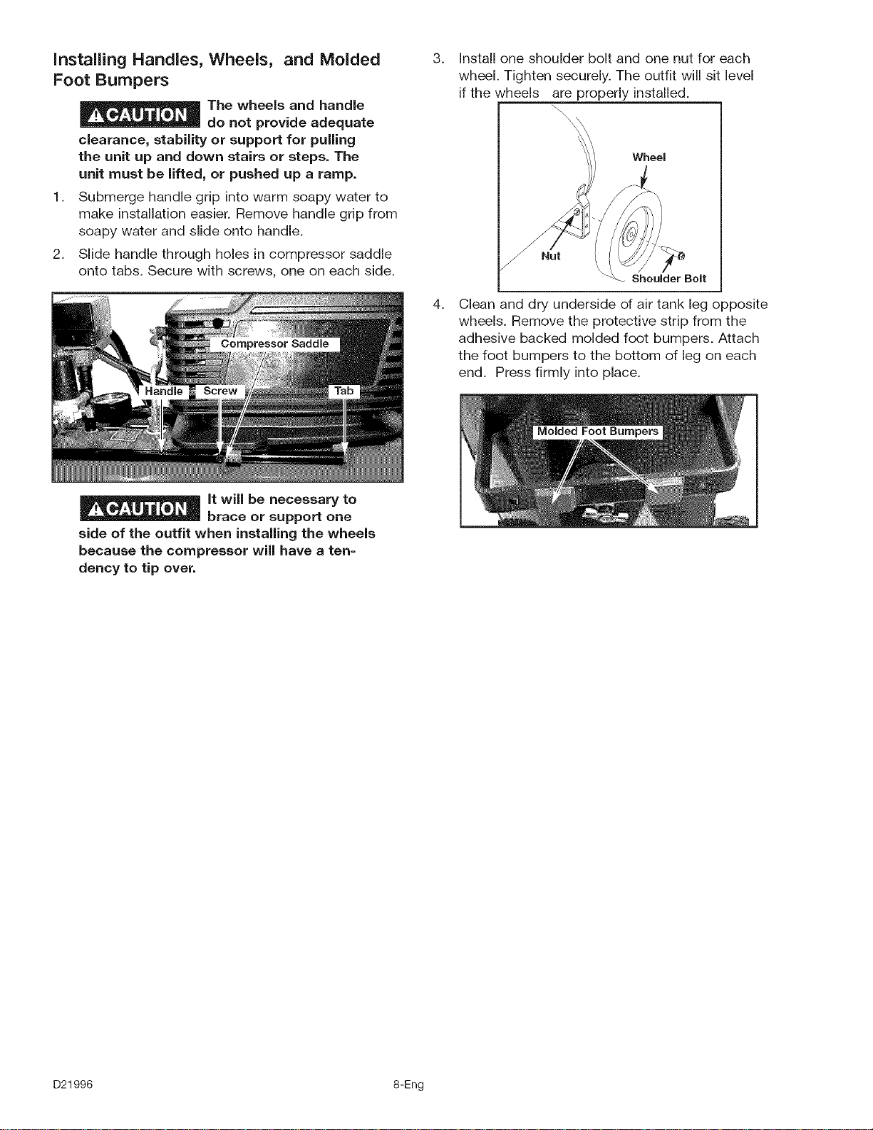
Slide handle through holes in compressor saddle
onto tabs. Secure with screws, one on each side.
3. Install one shoulder bolt and one nut for each
wheel. Tighten securely. The outfit will sit level
if the wheels are properly installed.
\\\\
\
Wheel
.
Shoulder Bolt
Clean and dry underside of air tank leg opposite
wheels. Remove the protective strip from the
adhesive backed molded foot bumpers. Attach
the foot bumpers to the bottom of leg on each
end. Press firmly into place.
It will be necessary to
brace or support one
side of the outfit when installing the wheels
because the compressor will have a ten=
dency to tip over.
D21996 8-Eng
HOW TO SET UP YOUR UNiT
Location of the Air Compressor
Locate the air compressor in a clean, dry and well
ventilated area. The air compressor should be located
at least 12" away from the wall or other obstructions
that will interfere with the flow of air. The air compres-
sor pump and shroud are designed to allow for proper
cooling. The ventilation openings on the compressor
are necessary to maintain proper operating tempera-
ture. Do not place rags or other containers on or near
these openings.
GROUNDING INSTRUCTIONS
RISK OF ELECTRICAL
SHOCK. In the event of a
short circuit, grounding reduces the risk of
shock by providing an escape wire for the
electric current. This air compressor must be
properly grounded.
The portable air compressor is equipped with a cord
having a grounding wire with an appropriate ground-
ing plug (see following illustrations). The plug must be
used with an outlet that has been installed and
grounded in accordance with all local codes and ordi-
nances.
1. The cord set and plug with this unit contains a
grounding pin. This plug MUST be used with a
grounded outlet.
IMPORTANT: The outlet being used must be installed
and grounded in accordance with all local codes and
ordinances.
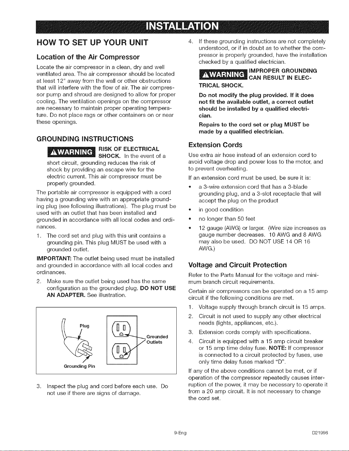
2. Make sure the outlet being used has the same
configuration as the grounded plug. DO NOT USE
AN ADAPTER. See illustration.
_.._ Grounded
7 Outlets
3. Inspect the plug and cord before each use. Do
not use if there are signs of damage.
.
If these grounding instructions are not completely
understood, or if in doubt as to whether the com-
pressor is properly grounded, have the installation
checked by a qualified electrician.
IMPROPER GROUNDING
RESULT iN ELEC=
TRICAL SHOCK.
Do not modify the plug provided. If it does
not fit the available outlet, a correct outlet
should be installed by a qualified electri=
clan.
Repairs to the cord set or plug MUST be
made by a qualified electrician.
Extension Cords
Use extra air hose instead of an extension cord to
avoid voltage drop and power loss to the motor, and
to prevent overheating.
If an extension cord must be used, be sure it is:
• a 3-wire extension cord that has a 3-blade
grounding plug, and a 3-slot receptacle that will
accept the plug on the product
in good condition
no longer than 50 feet
12 gauge (AWG) or larger. (Wire size increases as
gauge number decreases. 10 AWG and 8 AWG
may also be used. DO NOT USE 14 OR 16
AWG.)
Voltage and Circuit Protection
Refer to the Parts Manual for the voltage and mini-
mum branch circuit requirements.
Certain air compressors can be operated on a 15 amp
circuit ifthe following conditions are met.
1. Voltage supply through branch circuit is 15 amps.
2. Circuit is not used to supply any other electrical
needs (lights, appliances, etc.).
3. Extension cords comply with specifications.
4. Circuit isequipped with a 15 amp circuit breaker
or 15 amp time delay fuse. NOTE: If compressor
isconnected to a circuit protected by fuses, use
only time delay fuses marked "D'.
If any of the above conditions cannot be met, or if
operation of the compressor repeatedly causes inter-
ruption of the power, it may be necessary to operate it
from a 20 amp circuit. It is not necessary to change
the cord set.
9-Eng D21996
Know Your Air Compressor
READ THIS OWNER'S MANUAL AND SAFETY RULES BEFORE OPERATING YOUR UNIT. Compare the illustra-
tions with your unit to familiarize yourself with the location of various controls and adjustments. Save this manual
for future reference.
Description of Operation
Become familiar with these controls before operating
the unit.
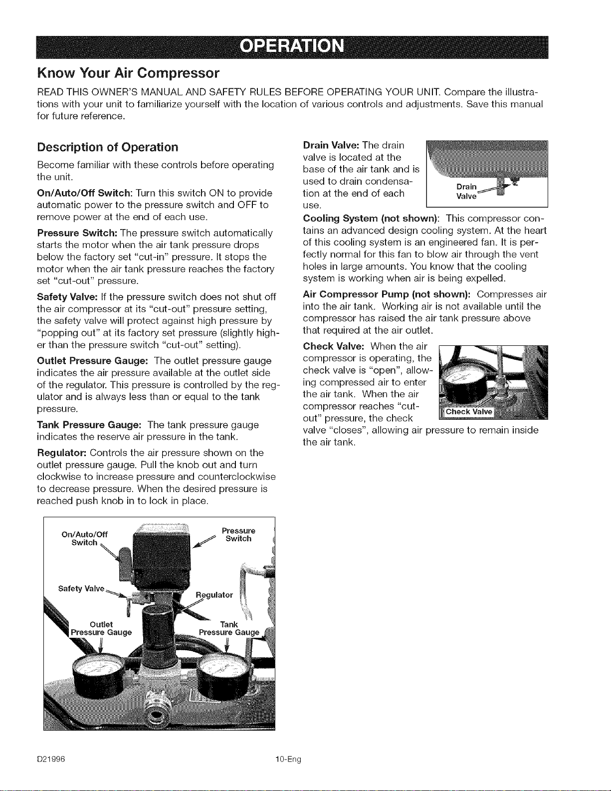
On/Auto/Off Switch: Turn this switch ON to provide
automatic power to the pressure switch and OFF to
remove power at the end of each use.
Pressure Switch: The pressure switch automatically
starts the motor when the air tank pressure drops
below the factory set "cut-in" pressure. It stops the
motor when the air tank pressure reaches the factory
set "cut-out" pressure.
Safety Valve: If the pressure switch does not shut off
the air compressor at its "cut-out" pressure setting,
the safety valve will protect against high pressure by
"popping out" at its factory set pressure (slightly high-
er than the pressure switch "cut-out" setting).
Outlet Pressure Gauge: The outlet pressure gauge
indicates the air pressure available at the outlet side
of the regulator. This pressure is controlled by the reg-
ulator and is always less than or equal to the tank
pressure.
Tank Pressure Gauge: The tank pressure gauge
indicates the reserve air pressure in the tank.
Regulator: Controls the air pressure shown on the
outlet pressure gauge. Pull the knob out and turn
clockwise to increase pressure and counterclockwise
to decrease pressure. When the desired pressure is
reached push knob in to lock in place.
Drain Valve: The drain
valve is located at the
base of the air tank and is
used to drain condensa-
Drain
tion at the end of each Valve
use.
Cooling System (not shown): This compressor con-
tains an advanced design cooling system. At the heart
of this cooling system is an engineered fan. It is per-
fectly normal for this fan to blow air through the vent
holes in large amounts. You know that the cooling
system is working when air is being expelled.
Air Compressor Pump (not shown): Compresses air
into the air tank. Working air is not available until the
compressor has raised the air tank pressure above
that required at the air outlet.
Check Valve: When the air
compressor is operating, the
check valve is "open", allow-
ing compressed air to enter
the air tank. When the air
compressor reaches "cut-
out" pressure, the check
valve "closes", allowing air pressure to remain inside
the air tank.
On/Auto/Off Pressure
Switch _ Switch
D21996 10-Eng
How to Use Your Unit
How to Stop:
1. Set the On/Auto/Off lever to "OFF".
Before Starting
Break=in Procedure
Serious damage may result if the
following break-in instructions are
not closely followed.
This procedure is required before the air compressor
is put into service and when the check valve or a
complete compressor pump has been replaced.
1. Make sure the On/Auto/Off lever is in the "OFF"
position.
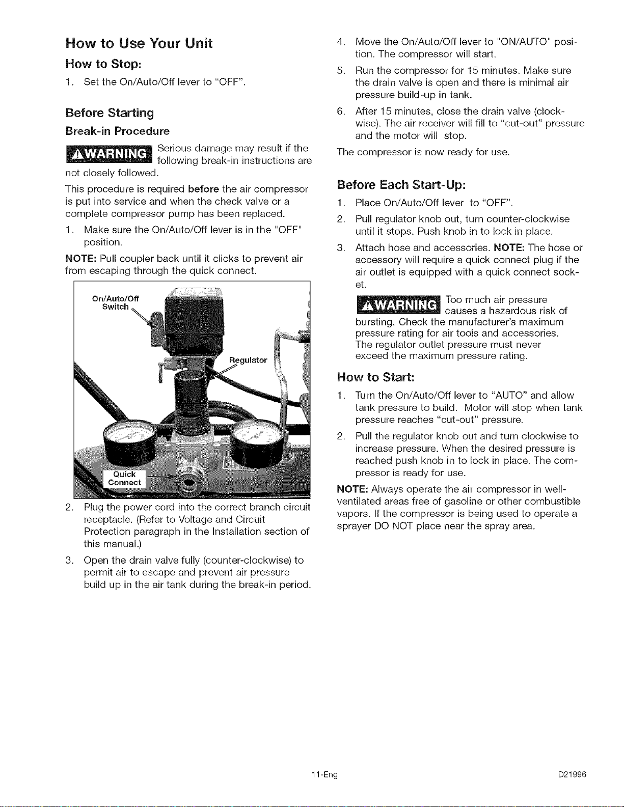
NOTE: Pull coupler back until it clicks to prevent air
from escaping through the quick connect.
On/Auto/Off
Switch
2. Plug the power cord into the correct branch circuit
receptacle. (Refer to Voltage and Circuit
Protection paragraph in the Installation section of
this manual.)
3. Open the drain valve fully (counter-clockwise) to
permit air to escape and prevent air pressure
build up in the air tank during the break-in period.
4. Move the On/Auto/Off lever to "ON/AUTO" posi-
tion. The compressor will start.
5. Run the compressor for 15 minutes. Make sure
the drain valve is open and there is minimal air
pressure build-up in tank.
6. After 15 minutes, close the drain valve (clock-
wise). The air receiver will fill to "cut-out" pressure
and the motor will stop.
The compressor is now ready for use.
Before Each Start=Up:
1. Place On/Auto/Off lever to "OFF".
2. Pull regulator knob out, turn counter-clockwise
until it stops. Push knob in to lock in place.
3. Attach hose and accessories. NOTE: The hose or
accessory will require a quick connect plug ifthe
air outlet is equipped with a quick connect sock-
et.
Too much air pressure
causes a hazardous risk of
bursting. Check the manufacturer's maximum
pressure rating for air tools and accessories.
The regulator outlet pressure must never
exceed the maximum pressure rating.
How to Start:
1. Turn the On/Auto/Off lever to "AUTO" and allow
tank pressure to build. Motor will stop when tank
pressure reaches "cut-out" pressure.
2. Pull the regulator knob out and turn clockwise to
increase pressure. When the desired pressure is
reached push knob in to lock in place. The com-
pressor is ready for use.
NOTE: Always operate the air compressor in well-
ventilated areas free of gasoline or other combustible
vapors. If the compressor is being used to operate a
sprayer DO NOT place near the spray area.
11-Eng D21996
Customer Responsibilities
Daily or after
Before each use
each use
Check Safety Valve •
Drain Tank •
NOTE: See "Operation" section for the location of
controls.
To Check Safety Valve
If the safety valve does
not work properly, over-
pressurization may occur, causing air tank
rupture or an explosion. Before starting com-
pressor, pull the ring on the safety valve to
make sure that the safety valve operates
freely. If the valve is stuck or does not operate
smoothly, it must be replaced with the same
type of valve.
To
1.
2.
3.
4.
5.
6.
Drain Tank
Set the On/Auto/Off lever to "OFF".
Pull the regulator knob out and turn clockwise to
set the outlet pressure to zero.
Remove the air tool or accessory.
Pull ring on safety valve allowing air to bleed from
the tank until tank pressure is approximately 20
psi. Release safety valve ring.
Drain water from air tank by opening drain valve
(counter-clockwise) on bottom of tank.
Water will condense in
the air tank. If not
drained, water will corrode and weaken the air
tank causing a risk of air tank rupture.
After the water has been drained, close the drain
valve (clockwise). The air compressor can now
be stored.
NOTE: If drain valve is plugged, release all air pres-
sure. The valve can then be removed, cleaned, then
reinstalled.
D21996 12-Eng
Unit cycles automatically when power is on. When doing Maintenance, you may be exposed
to voltage sources, compressed air or moving parts. Personal injuries can occur. Before per-
forming any Maintenance or repair, unplug the compressor and bleed off all air pressure.
ALL MAINTENANCE AND REPAIR OPERATIONS NOT LISTED MUST BE PERFORMED BY
TRAINED SERVICE TECHNiCiAN.
Before servicing:
• Unplug or disconnect electrical supply to the
air compressor.
Bleed tank of pressure.
Allow the air compressor to cool.
To Replace or Clean Check Valve
1. Release all air pressure from air tank. See "To
Drain Tank" in the Maintenance section.
2. Unplug outfit.
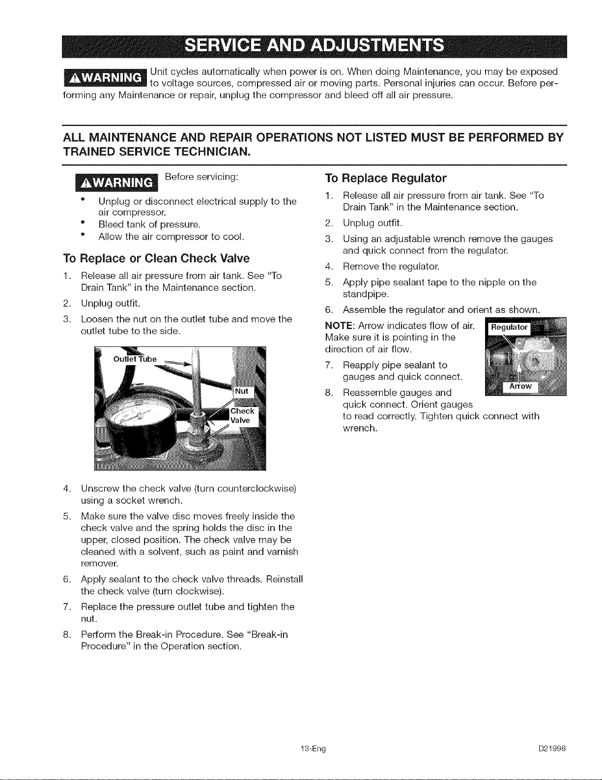
3. Loosen the nut on the outlet tube and move the
outlet tube to the side.
To Replace Regulator
1. Release all air pressure from air tank. See "To
Drain Tank" in the Maintenance section.
2. Unplug outfit.
3. Using an adjustable wrench remove the gauges
and quick connect from the regulator.
4. Remove the regulator.
5. Apply pipe sealant tape to the nipple on the
standpipe.
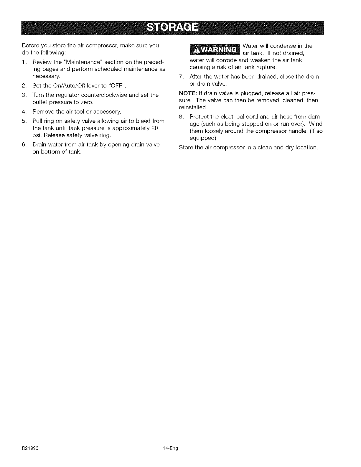
6. Assemble the regulator and orient as shown.
NOTE: Arrow indicates flow of air.
Make sure it is pointing in the
direction of air flow.
7_
8.
Reapply pipe sealant to
gauges and quick connect.
Reassemble gauges and
quick connect. Orient gauges
to read correctly. Tighten quick connect with
wrench.
4_
5.
6_
7.
8.
Unscrew the check valve (turn counterclockwise)
using a socket wrench.
Make sure the valve disc moves freely inside the
check valve and the spring holds the disc in the
upper, closed position. The check valve may be
cleaned with a solvent, such as paint and varnish
remover.
Apply sealant to the check valve threads. Reinstall
the check valve (turn clockwise).
Replace the pressure outlet tube and tighten the
nut.
Perform the Break-in Procedure. See "Break-in
Procedure" in the Operation section.
13-Eng D21996
Before you store the air compressor, make sure you
do the following:
1. Review the "Maintenance" section on the preced-
ing pages and perform scheduled maintenance as
necessary.
2. Set the On/Auto/Off lever to "OFF".
3. Turn the regulator counterclockwise and set the
outlet pressure to zero.
4. Remove the air tool or accessory.
5. Pull ring on safety valve allowing air to bleed from
the tank until tank pressure is approximately 20
psi. Release safety valve ring.
6. Drain water from air tank by opening drain valve
on bottom of tank.
7_
Water will condense in the
air tank. If not drained,
water will corrode and weaken the air tank
causing a risk of air tank rupture.
After the water has been drained, close the drain
or drain valve.
NOTE: If drain valve is plugged, release all air pres-
sure. The valve can then be removed, cleaned, then
reinstalled.
8. Protect the electrical cord and air hose from dam-
age (such as being stepped on or run over). Wind
them loosely around the compressor handle. (If so
equipped)
Store the air compressor in a clean and dry location.
D21996 14-Eng
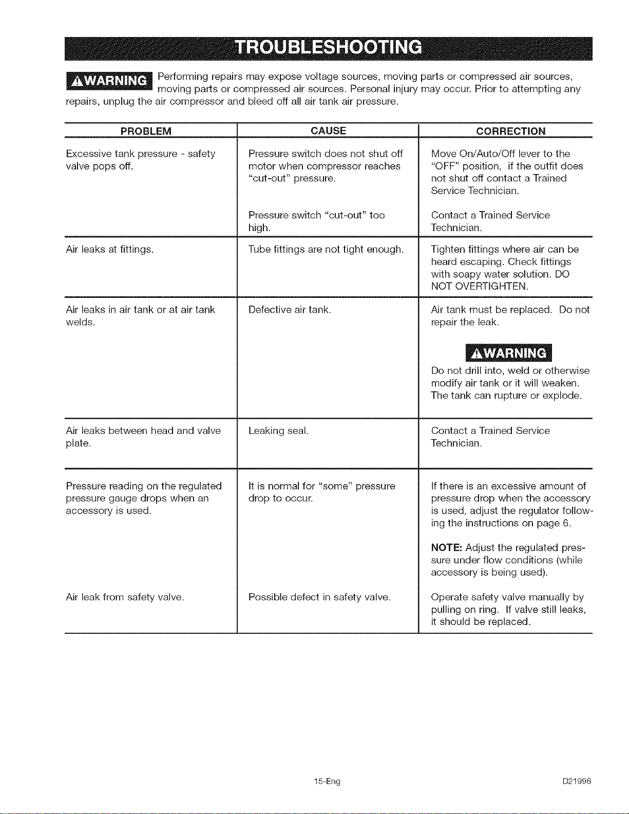
Performing repairs may expose voltage sources, moving parts or compressed air sources,
moving parts or compressed air sources. Personal injury may occur. Prior to attempting any
repairs, unplug the air compressor and bleed off all air tank air pressure.
CORRECTIONPROBLEM
Excessive tank pressure - safety
valve pops off.
Air leaks at fittings.
Air leaks in air tank or at air tank
welds.
CAUSE
Pressure switch does not shut off
motor when compressor reaches
"cut-out" pressure.
Air leaks between head and valve
plate.
Pressure reading on the regulated
pressure gauge drops when an
accessory is used.
Air leak from safety valve.
Pressure switch "cut-out" too
high.
Tube fittings are not tight enough.
Defective air tank.
Leaking seal.
It is normal for "some" pressure
drop to occur.
Possible defect in safety valve.
Move On/Auto/Off lever to the
"OFF" position, if the outfit does
not shut off contact a Trained
Service Technician.
Contact a Trained Service
Technician.
Tighten fittings where air can be
heard escaping. Check fittings
with soapy water solution. DO
NOT OVERTIGHTEN.
Air tank must be replaced. Do not
repair the leak.
Do not drill into, weld or otherwise
modify air tank or it will weaken.
The tank can rupture or explode.
Contact a Trained Service
Technician.
If there is an excessive amount of
pressure drop when the accessory
is used, adjust the regulator follow-
ing the instructions on page 6.
NOTE: Adjust the regulated pres-
sure under flow conditions (while
accessory is being used).
Operate safety valve manually by
pulling on ring. If valve still leaks,
it should be replaced.
15-Eng D21996
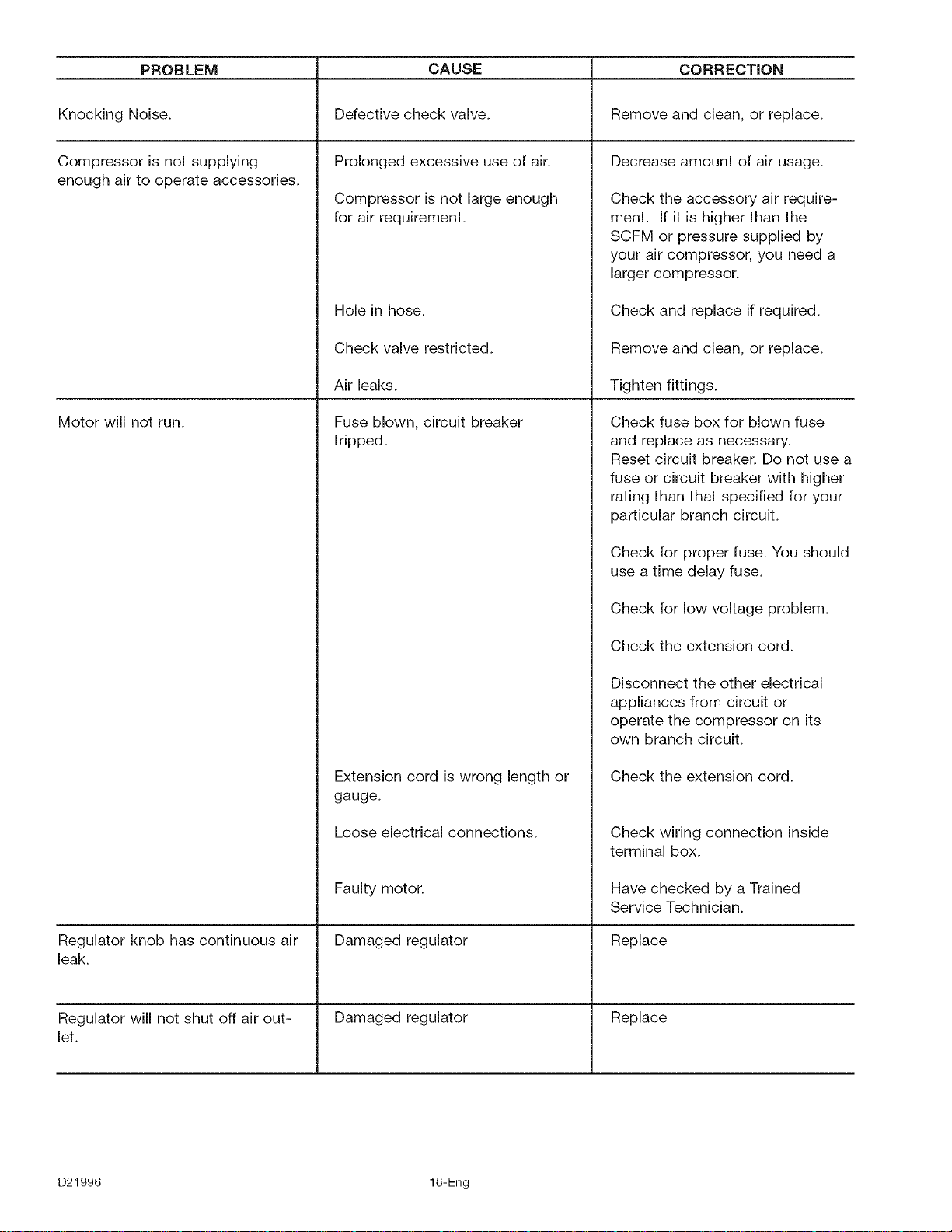
PROBLEM CORRECTION
Knocking Noise. Remove and clean, or replace.
Decrease amount of air usage.Compressor is not supplying
enough air to operate accessories.
Motor will not run.
Regulator knob has continuous air
leak.
Regulator will not shut off air out-
let.
CAUSE
Defective check valve.
Prolonged excessive use of air.
Compressor is not large enough
for air requirement.
Hole in hose.
Check valve restricted.
Air leaks.
Fuse blown, circuit breaker
tripped.
Extension cord is wrong length or
gauge.
Loose electrical connections.
Faulty motor.
Damaged regulator
Damaged regulator
Check the accessory air require-
ment. If it is higher than the
SCFM or pressure supplied by
your air compressor, you need a
larger compressor.
Check and replace if required.
Remove and clean, or replace.
Tighten fittings.
Check fuse box for blown fuse
and replace as necessary.
Reset circuit breaker. Do not use a
fuse or circuit breaker with higher
rating than that specified for your
particular branch circuit.
Check for proper fuse. You should
use a time delay fuse.
Check for low voltage problem.
Check the extension cord.
Disconnect the other electrical
appliances from circuit or
operate the compressor on its
own branch circuit.
Check the extension cord.
Check wiring connection inside
terminal box.
Have checked by a Trained
Service Technician.
Replace
Replace
D21996 16-Eng
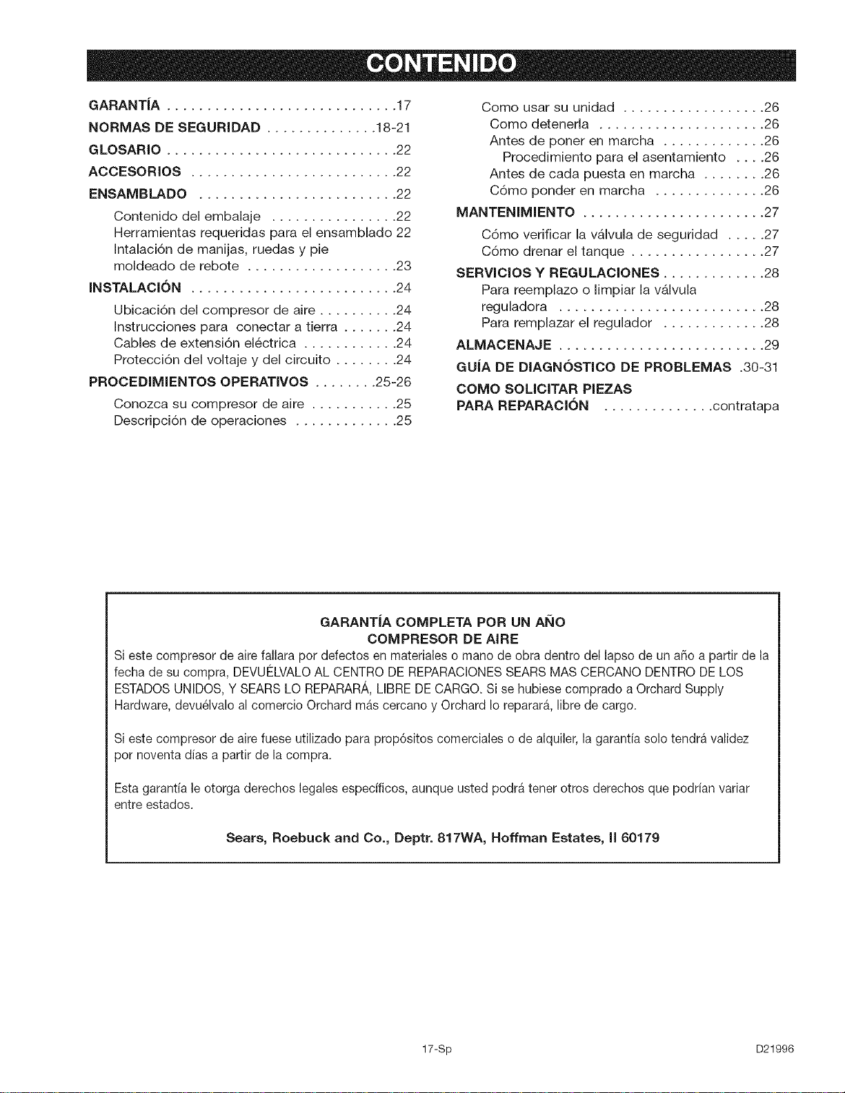
GARANTIA ............................. 17
NORMAS DE SEGURIDAD .............. 18-21
GLOSARIO ............................. 22
ACCESORIOS .......................... 22
ENSAMBLADO ......................... 22
Contenido del embalaje ................ 22
Herramientas requeridas para el ensamblado 22
Intalaci6n de manijas, ruedas y pie
moldeado de rebote ................... 23
INSTALACl6N .......................... 24
Ubicaci6n del compresor de aire .......... 24
Instrucciones para conectar a tierra ....... 24
Cables de extensi6n el_ctrica ............ 24
Protecci6n del voltaje y del circuito ........ 24
PROCEDIMIENTOS OPERATIVOS ........ 25-26
Conozca su compresor de aire ........... 25
Descripci6n de operaciones ............. 25
Como usar su unidad .................. 26
Como detenerla ..................... 26
Antes de poner en marcha ............. 26
Procedimiento para el asentamiento .... 26
Antes de cada puesta en marcha ........ 26
C6mo ponder en marcha .............. 26
MANTENIMIENTO ....................... 27
C6mo verificar la vAIvula de seguridad ..... 27
C6mo drenar el tanque ................. 27
SERVIClOS Y REGULACIONES ............. 28
Para reemplazo o limpiar la v&lvula
reguladora .......................... 28
Para remplazar el regulador ............. 28
ALMACENAJE .......................... 29
GUJA DE DIAGNOSTICO DE PROBLEMAS .30-31
COMO SOLICITAR PIEZAS
PARA REPARACION .............. contratapa
GARANTIA COMPLETA POR UN ANO
COMPRESOR DE AIRE
Si este compresor de aire fallara pot defectos en materialeso mano de obra dentro del lapso de un aSo a partir de la
fecha de su compra, DEVUELVALOAL CENTRO DE REPARACIONESSEARSMAS CERCANODENTRODE LOS
ESTADOSUNIDOS,Y SEARSLO REPARARA,LIBREDE CARGO.Si se hubiese comprado a Orchard Supply
Hardware, devu61valoal comercio Orchard mas cercano y Orchard Ioreparara, libre de cargo.
Si este compresor de aire fuese utilizado para prop6sitos comerciales o de alquiler, la garantfa solo tendra validez
pot noventa dias a partir de la compra.
Esta garantia le otorga derechos legales especificos, aunque usted podra tenet otros derechos que podrian variar
entre estados.
Sears, Roebuck and Co., Deptr. 817WA, Hoffman Estates, li 60179
17-Sp D21996
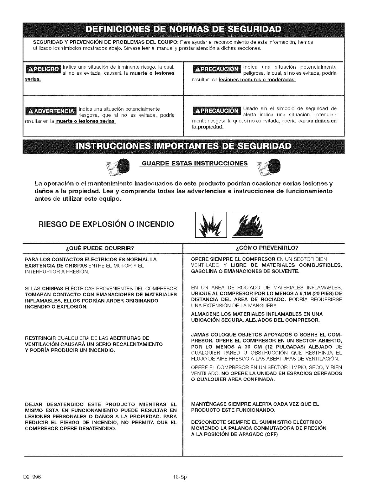
SEGURIDADY PREVENCI6N DE PROBLEMAS DEL EQUIPO: Para ayudar al reconocimiento de esta informaci6n, hemos
utilizado los simbolos mostrados abajo. Sfrvase leer el manual y prestar atenci6n a dichas secciones.
_ Indica una situaci6n de inminente riesgo, la cual,
si no es evitada, causara la muerte o lesiones
serias.
_ Indica una situaci6n potencialmente
riesgosa, que si no es evitada, podrfa
resultar en la muerte o lesiones serias.
_lndica una situaci6n potencialmente
peligrosa, la cual, si no es evitada, podrfa
resultar en lesiones menores o moderadas.
_ Usado sin el simbolo de seguridad de
alerta indica una situaci6n potencial-
mente riesgosa la que, si no es evitada, podria causar da6os en
la propiedad.
l GUARDE ESTAS INSTRUCCIONES %0
La operaci6n o el mantenimiento inadecuados de este producto podrian ocasionar serias lesiones y
daSos a la propiedad. Lea y comprenda todas las advertencias e instrucciones de funcionamiento
antes de utilizar este equipo.
RIESGO DE EXPLOSI()N 0 INCENDIO
&QUa: PUEDE OCURRIR?
PARA LOS CONTACTOS ELECTRICOS ES NORMAL LA
EXiSTENCIA DE CHISPAS ENTRE EL MOTOR Y EL
INTERRUPTOR A PRESION.
SI LAS CHISPAS ELECTRICAS PROVENIENTES DEL COMPRESOR
TOMARAN CONTACTO CON EMANACIONES DE MATERIALES
INFLAMABLES, ELLOS PODRJAN ARDER ORIGINANDO
INCENDIO O EXPLOSION.
RESTRINGIR CUALQUIERA DE LAS ABERTURAS DE
VENTILACION CAUSAR/_ UN SERIO RECALENTAMIENTO
Y PODRJA PRODUCIR UN INCENDIO.
DEJAR DESATENDIDO ESTE PRODUCTO MIENTRAS EL
MISMO EST,& EN FUNCIONAMIENTO PUEDE RESULTAR EN
LESIONES PERSONALES O DA_IOS A LA PROPIEDAD. PARA
REDUCIR EL RIESGO DE INCENDIO, NO PERMITA QUE EL
COMPRESOR OPERE DESATENDIDO.
&COMO PREVENIRLO?
OPERE SlEMPRE EL COMPRESOR EN UN SECTOR BEN
VENTILADO Y LIBRE DE MATERIALES COMBUSTIBLES,
GASOLINA O EMANACIONES DE SOLVENTE.
EN UN AREA DE ROCIADO DE MATERIALES INFLAMABLES,
UBIQUE AL COMPRESOR POR LO MENOS A 6,1M (20 PIES} DE
DISTANClA DEL AREA DE ROClADO. PODR{A REQUERIRSE
UNA EXTENSION DE LA MANGUERA.
ALMACENE LOS MATERIALES INFLAMABLES EN UNA
UBICACION SEGURA, ALEJADOS DEL COMPRESOR.
JAM,&S COLOQUE OBJETOS APOYADOS O SOBRE EL COM-
PRESOR. OPERE EL COMPRESOR EN UN SECTOR ABIERTO,
POR LO MENOS A 30 CM (12 PULGADAS) ALEJADO DE
CUALQUIER PARED U OBSTRUCCION QUE RESTRINJA EL
FLUJO DE AIRE FRESCO A LAS ABERTURAS DE VENTILACION.
OPERE EL COMPRESOR EN UN SECTOR LIMPIO, SECO, Y BEN
VENTILADO. NO OPERE LA UNIDAD EN ESPAClOS CERRADOS
O CUALQUIER AREA CONFINADA.
MANTI_NGASE SIEMPRE ALERTA CADA VEZ QUE EL
PRODUCTO ESTE FUNCIONANDO.
DESCONECTE SIEMPRE EL SUMINISTRO ELECTRICO
MOVIENDO LA PALANCA CONMUTADORA DE PRESION
A LA POSICION DE APAGADO (OFF}
D21996 18-Sp
RIESGO DE EXPLOSI(_N
TANQUE DE AIRE: LAS SIGUIENTES CONDICIONES PUEDEN DETERMINAR EL DEBILITAMIENTO
DEL TANQUE, Y ORIGiNAR UNA VIOLENTA EXPLOSION DEL MISMO, SIENDO CAUSA DE DAKIOS A
LA PROPIEDAD 0 LESIONES SERIAS.
2.
3.
_,QU_:PUEDE OCURRIR? _,C6MO PREVENIRLO?
DRENAJE INADECUADO DEL AGUA CONDENSADA EN
EL TANQUE, SIENDO LA CAUSA DEL 0XIDO QUE REDUCE
EL ESPESOR DEL TANQUE DE ACERO.
MODIFICACIONES O INTENTO DE REPARACIONES AL
TANQUE.
MODiFiCACiONES NO AUTORiZADAS A LA V,_LVULA DE
DESCARGA, V/_.LVULA DE SEGURiDAD O CUALQUIER
OTRO COMPONENTE QUE CONTROLE LA PRESION DEL
TANQUE.
LA VIBRACI6N EXCESiVA PUEDE DEBiLiTAR EL TANQUE
DE AiRE Y CAUSAR SU RUPTURA O EXPLOSION.
AGREGADOS Y ACCESOR#OS
EL EXCESO A LOS VALORES DE PRESI6N ESTABLECIDOS
PARA LAS HERRAMIENTAS NEUMATICAS, PISTOLAS ROCIADO-
RAS, ACCESORIOS ACTIVADOS POR AIRE, CUBIERTAS Y OTROS
OBJETOS INFLABLES, PUEDE CAUSAR SU EXPLOSION O SER
ARROJADOS, PUDIENDO OCASIONAR SERIAS LESIONES.
DRENE EL TANQUE DIARiAMENTE O DESPUES DE CADA USO.
SI EL TANQUE GENERA UNA PCRDIDA, REEMPL/_CELO
INMEDIATAMENTE CON UN NUEVO TANQUE O REEMPLACE EL
COMPRESOR COMPLETO.
JAMAS PERFORE, SUELDE, O EFECTUE MODIFICACI6N ALGUNA
AL TANQUE O SUS ACCESORIOS.
EL TANQUE EST/k DISENADO PARA RESISTIR PRESIONES
OPERATIVAS ESPECiFICAS. JAMAS EFECTUE AJUSTES O
SUSTITUYA PARTES QUE ALTEREN LAS REGULAClONES DE
PRESION ORIGINALES DE FABRICA.
PARA UN CONTROL ESENCIAL DE LA PRESION, DEBE USTED
INSTALAR UN REGULADOR Y UN MEDIDOR DE PRESI6N A LA
SAMDA DEL AIRE DE SU COMPRESOR. (SI NO ESTUNIER
EQUIPADO) SIGA LAS RECOMENDACIONES DE LOS
FABRICANTES DE SU EQUIPO Y JAMAS EXCEDA LOS VALORES
MAXIMOS DE PRESION PERMITIDOS PARA LOS ACCESORIOS.
JAMAS USE EL COMPRESOR PARA INFLAR OBJETOS QUE
REQUIEREN POCA O BAJA PRESI6N, TALES COMO
JUGUETES PARA LOS NIhIOS, PELOTAS DE FUTBOL, PELOTAS
DE BASQUET, ETC.
RIESGO DE OBJETOS ARROJADOS POR EL AIRE.
_QUEPUEDE OCURRIR?
EL CHORRO DE AIRE COMPRIMIDO PUEDE CAUSAR DAI_IOS
SOSRE LOS TEJIDOS BLANDOS DE LA PIEL EXPUESTA, Y
PUEDE PROPULSAR SUCIEDAD, ASTILLAS, PARTICULAS
SUELTASY PEQUENOSOBJETOS A ALTAVELOClDAD, OCASIONANDO
DANOS A LA PROPIEDAD O LESIONES PERSONALES.
_,C6MO PREVENIRLO?
AL UTILIZAR EL COMPRESOR, USE SIEMPRE ANTEOJOS DE
SEGURIDAD ANSI Z87.1 APROBADOS, CON PROTECCION
LATERAL.
JAMAS APUNTE NINGUNA BOQUILLA O PULVERIZADOR
HACIA PARTES DEL CUERPO, A OTRAS PERSONAS O
ANIMALES.
APAGUE SIEMPRE EL COMPRESOR Y PURGUE LA PRESI6N
DE LA MANGUERA DEL AIRE Y DEL TANQUE, ANTES DE INTENTAR
EL MANTENIMIENTO, EL ACOPLE DE HERRAMIENTAS O
ACCESORIOS.
19-Sp D21996
RIESGO DE DESCARGA ELC:CTRICA
_,QU_: PUEDE OCURRIR? &COMO PREVENIRLO?
SU COMPRESOR DE AIRE EST/_ ACCIONADO POR ELECTRICIDAD.
COMO CUALQUIER OTRO DISPOSITIVO ELCCTRICO IMPULSADO
EL¢CTRICAMENTE, 81 NO SE LO UTILIZA ADECUADAMENTE,
PODRJA CAUSARLE UNA DESCARGA ELECTRICA.
LAS REPARACIONES INTENTADAS POR PERSONAL NO
CALIFICADO PODRIAN OCASIONAR SERIAS LESIONES O LA
MUERTE POR ELECTROCUCION.
CONEXION A TIERRA: DEJAR DE PROVEER UNA ADECUADA
CONEXION A TIERRA A ESTE PRODUCTO PODRIA OCASIONAR
LESIONES SERIAS O LA MUERTE POR ELECTROCUClON. VER
INSTRUCCIONES PARA LA PUESTA A TIERRA.
JAMAS OPERE EL COMPRESOR A LA INTEMPERIE CUANDO
EST/_ LLOVlENDO O EN CONDICIONES DE HUMEDAD.
NUNCA OPERE EL COMPRESOR SIN SUS DEFENSAS O SUS
CUBIERTAS REMOVIDAS O DANADAS.
CUALQUIER CONEXION ELECTRiCA O REPARACION
REQUERIDA POR ESTE PRODUCTO DEBE SER EFECTUADA
POR PERSONAL AUTORIZADO DE LOS SERVlCENTROS DE
ACUERDO A LOS CODIGOS ELCCTRICOS NACIONALES Y
LOCALES.
ASEGURESE QUE EL ClRCUITO ELECTRICO AL CUAL ESTA
CONECTADO EL COMPRESOR, SUMINISTRA APROPIADA
CONEXION A TIERRA, TENSION CORRECTA Y UNA ADECUADA
PROTECClON DE FUSIBLES.
RIESGO DE INHALACION
_,QU_: PUEDE OCURRIR? _,C6MO PREVENIRLO?
EL AIRE COMPRIMIDO PROVENIENTE DEL COMPRESOR NO
ES SANO PARA RESPIRAR. EL CRORRO DE AIRE PUEDE
CONTENER MONOXIDO DE CARBONO, VAPORES TOXICOS O
PARTICULAS SOLIDAS PROVENIENTES DEL TANQUE. LA
INHALACION DE DICHOS CONTAMINANTES PUEDE LLEGAR A
CAUSAR SERIAS LESIONES O LA MUERTE.
EL ROCIADO DE MATERIALES TALES COMO PINTURA,
SOLVENTES, REMOVEDORES DE PINTURA, INSECTICIDAS, MATA
HIERBAS, CONTIENEN EMANACIONES DANINAS Y VENENOSAS.
EL AIRE OBTENIDO DIRECTAMENTE DEL COMPRESOR JAMAS
DEBER,'_SER UTILIZADO PARA PROVEER AIRE PARA CONSUMO
HUMANO. PARA PODER UTILIZAR EL AIRE PRODUCIDO POR
ESTE COMPRESOR Y HACERLO RESPIRABLE, DEBERAN
INBTALARSE UN FILTRO ADECUADO Y UN EQUIPO DE
SEGURIDAD INTERCALADO. LOS FILTROS INTERCALADOS
TANTO COMO EL EQUIPO DE SEGURIDAD UTILIZADO EN
CON JUNTO CON EL COMPRESOR, DEBERP, N SER CAPACES
DE PROCESAR EL TRATAMIENTO DEL AIRE DE ACUERDO A
TODOS LOS C6DIGOS LOCALES Y FEDERALES, PREVIO AL
CONSUMO HUMANO.
TRABAJE EN UN AREA CON BUENA VENTILACION CRUZADA.
LEA Y SIGA LAS INSTRUCCIONES DE SEGURIDAD PROVISTAS
EN EL ROTULO O EN LOS DATOS DE LAS HOJAS DE SEGURIDAD
DEL MATERIAL QUE ESTA PULVERIZANDO. USE EL RESPIRADOR
APROBADO NiOSH/MSHA DESIGNADO PARA UTILIZARSE CON
SU APLICACION ESPECJFICA.
D21996 20-Sp
RIESGO DE QUEMADURAS
_QUEPUEDE OCURRIR?
TOCAR EL METAL EXPUESTO TAL COMO EL CABEZAL DEL
COMPRESOR O LOS TUBOS DE SALIDA DEL ESCAPE, PUEDE
OCASIONARLE SERIAS QUEMADURAS.
&COMO PREVENIRLO?
JAMAS TOQUE PARTES DE METAL EXPUESTAS EN EL
COMPRESOR DURANTE O INMEDIATAMENTE DESPUES DE LA
OPERACION. EL COMPRESOR PERMANECERA CAMENTE
POR VARIOS MINUTOS LUEGO DE LA OPERACION.
NO LO CUBRA CON FUNDAS PROTECTORAS O INTENTE EL
MANTENIMIENTO HASTA QUE LA UNIDAD HAYA ALCANZADO
SU ENFRIAMIENTO.
RIESGO DE PARTES M()VILES
&QUa: PUEDE OCURRIR? &COMO PREVENIRLO?
PARTES MOVIBLES TALES COMO LA POLEA, EL VOLANTE Y LA
CORREA PODRiAN SER LA CAUSA DE SERIAS LESIONES SI
ELLAS ENTRARAN EN CONTACTO CON USTED O SUS ROPAS.
INTENTAR OPERAR EL COMPRESOR CON SUS PARTES
DA_IADAS O FALTANTES, O LA REPARACION DEL COMPRESOR
CON SUS PROTECClONES REMOVIDAS, PUEDE EXPONERLO
A USTED A PARTES MOVlBLES, QUE PODRIAN RESULTAR EN
LESIONES SERIAS.
NUNCA OPERE EL COMPRESOR SiN SUS DEFENSAS O SUS
CUBIERTAS REM©VIDAS O DANADAS.
CUALQUIER REPARACION REQUERIDA POR ESTE PRODUCTO
DEBE SER EFECTUADA POR PERSONAL AUTORIZADO DE
LOS SERVlCENTROS.
RIESGO DE CAIDA
&QUE PUEDE OCURRIR? &COMO PREVENIRLO?
UN COMPRESOR PORT/kTIL PUEDE CAERSE DE LA MESA, EL
BANCO DETRABAJO O DEL TECHO DAI_IANDO AL COMPRESOR Y
PUDIENDO RESULTAR EN SERIAS LESIONES O LA MUERTE
DEL OPERADOR,
OPERE SIEMPRE EL COMPRESOR EN UNA POSICION
ESTABLE Y SEGURA A FIN DE PREVENIR EL MOVIMIENTO
ACCIDENTAL DE LA UNIDAD. JAMAS OPERE EL COMPRESOR
SOBRE UN TECHO U OTRA POSICION ELEVADA. UTILICE
MANGUERAS ADIClONALES DE AIRE PARA ALCANZAR
POSIClONES ALTAS.
RIESGO DE DANOS A LA PROPIEDAD AL TRANSPORTAR
EL COMPRESOR
(Fuego, inhalaci6n, da_o a la superficie de vehiculos}
Para unidades que requieran aceite en la bomba o motores a gasolina.
&QUa: PUEDE OCURRIR? &COMO PREVENIRLO?
EL ACEITE PUEDE DERRAMARSE Y ELLO PODR{A RESULTAR
EN SERIAS LESIONES O LA MUERTE DEBIDO AL RIESGO DE
INCENDIO O INHALACION. EL DERRAME DE ACEITE DAi_A
ALFOMBRAS, PINTURAS U OTRAS SUPERFICIES DE VEH{CULOS
O REMOLQUES.
DEPOSITE EL COMPRESOR SOBRE UNA ALFOMBRILLA PRO-
TECTORA CUANDO LO TRANSPORTE. A FIN DE PROTEGER AL
VEH{CULO DE PERDIDAS POR GOTEO, RETIRE EL COMPRESOR
DEL VEHICULO INMEDIATAMENTE DESPUES DE SU ARRIBO AL
DESTINO.
21-Sp D21996
Familiaricesecon estos terminos antesde operar la unidad: Presi6n de conexi6n: Entanto el motoresta detenido, la
CFM: (Cubic feet per minute) PiescObicos por minute.
SCFM: (Standard cubic feet per minute)Pie cL_bicoestandar por min-
ute; unidad de medida de entrega de aire.
PSIG:(Pounds per square inch gauge) Libras per pulgada cuadrada;
unidad que mide la presi6n.
ASME: (American Society of Mechanical Engineers) La
Sociedad Americana de Ingenieros mecanicos verific6,
inspeccion6 y registr6 para permitir Iograr los estandares de
la ASME.
C6digo de certificaci6n: Los productos que usan una o mas de
las siguientes mamas: UL, CUL, ETL,CETL, han side evaluados pot
OSHA, laboratories independientescertificados en seguridad, y reLi-
nenlos estandaressuscriptos por los laboraterios dedicados a la
certificaci6n de la seguridad.
presi6n deltanque de airedisminuyeen lamedidaen quese continLia
utilizandoel accesorio.Cuando lapresi6ndeltanquedesciendehasta
cierto nivel,el motorarrancaautom_.ticamente.Elvalor de la presi6n
quedeterminael arranqueautomatico delmotor se llama "presi6nde
conexi6n".
Presi6n de corte: Cuando uncompresor seponeen marchay
comienzaa funcionar,la presi6ndeltanquedel airecomienza acrecer.
El incrementoIlegahastaun ciertovalor de presi6nantesde que el
motor sedetengaautomaticamente,protegiendo altanque de aire
contra un valorde presi6nmas elevadoque el de su capacidad.El
valorde dicha presi6n elevadaa la queel motor se detienees Ilamado
"presi6nde corte".
Ramal: Circuito quetransporta electricidaddesde el panelde control
hasta eltomacorriente.
Estaunidad essuficiente para abastecerde energfaa los siguientesaccesorios. Estosseencuentrandisponibles a trav6sdel
catalogo para herramientasel6ctricasy manuales,en cualquierade los comercios que mantiene la lineacompleta de SEARS.
Accesorios Herramientas para carpinteda
* Filtro de intercalar * M;_quinaclavadora / abrochadora
* Boquilla para inflar cubiertas. * Clavadora para construcci6n /
* Juego de conexi6n rapida (varias abrochadora
medidas) Impulsor de llaves de tubo
* Reguladores de presi6n de aire. * Llave de 1/2" de impacto
* Lubricadores para niebla de aceite. * Llave de 3/8" de impacto / mariposa
Manguera de aire: * Llave de 3/8" a trinquete
1/4", 3/8" o 1/2" DI. en distintas longi-
tudes. * Llave de 1/4" a trinquete
Herramientas pot especialidades Formado de material
Cepillo de aire • Martillo 2.625"
Pistola infladera / sopladera • Martillo 1.625"
Pistola engrasadora • Agujereadora de 3/8"
Pistola para aplicaci6n de sellador • Mini herramienta rotativa de alta velocidad
Limpiador de motor • Sierra reciprocante
Arenadora • Recortadora de chapa
Pintado pot rociado
* Pistola rociadora multiprop6sito
* Pistola rociadera para uso automotor
* Pistola rociadora HVLP
Terminaciones / lijado
* Lijadora oscilante
* Lijadora en linea recta
Contenido del embalaje
1- Compresor de aire
2- Ruedas
2 - Bulones de tope, 3/8 - 16
2 - Tuerca hexagonal, 3/8 - 16
2 - Pie moldeado de rebote
1- Mango
1 - Agarradera de mango
Herramientas requeridas para el ensamblado
1 - Llave de tubo o Ilave de extremo abierto 9/16"
1 - Llave de tubo 3/8"
2 - Tornillo #10 - 16 x 1.00
D21996 22-Sp
Instalaci6n de rnanijas, ruedas y pie mold=
eado de rebote
2_
Las ruedas y manija no
proveen una distancia adecua-
da, estabilidad ni soporte para levantar la unidad y
bajar escaleras o peldaSos. La unidad debe set
levantada o empujada sobre una rampa.
Sumerja el mango de agarre en una soluci6n
jabonosa tibia a fin de hacer su instalaci6n mAs sen-
cilia. Extraiga el mango de agarre de la soluci6n
jabonosa y deslicelo sobre la manija.
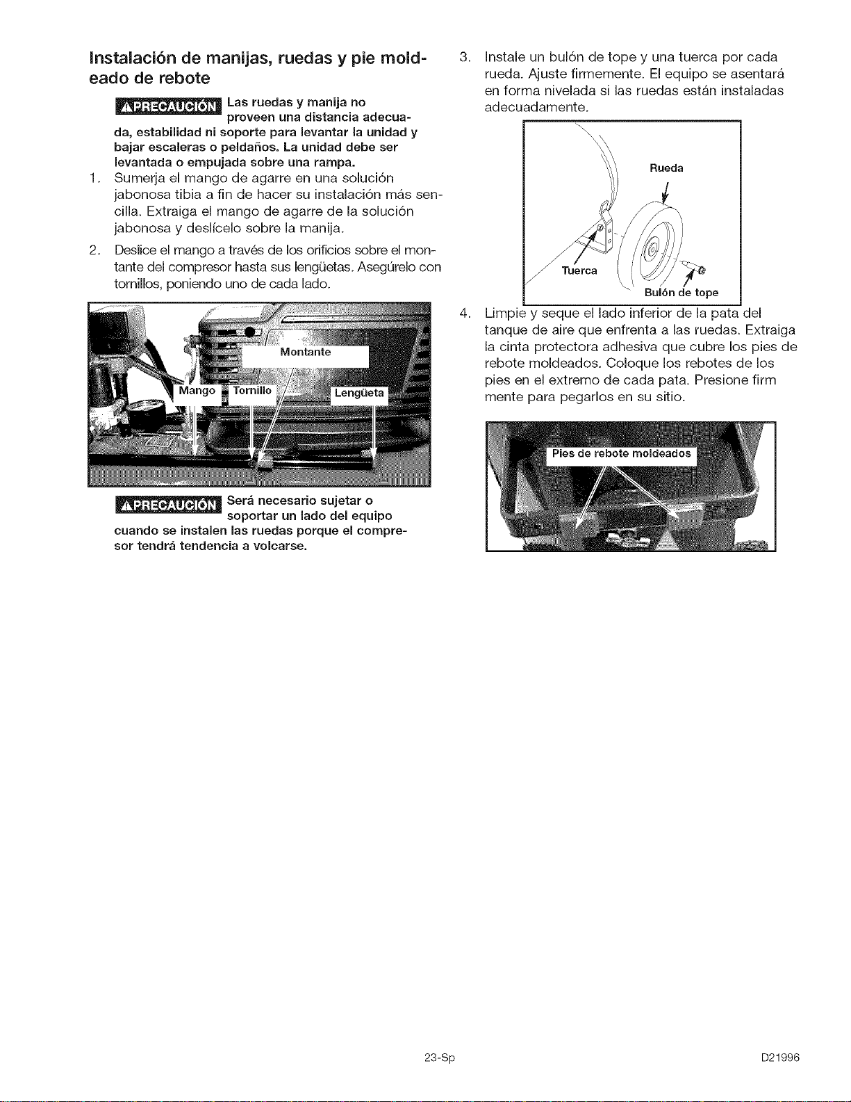
Deslice el mango a trav6s de los orificios sobre el mon-
tante del compresor hasta sus lengQetas. AsegQrelo con
tornillos, poniendo uno de cada lado.
3_
4_
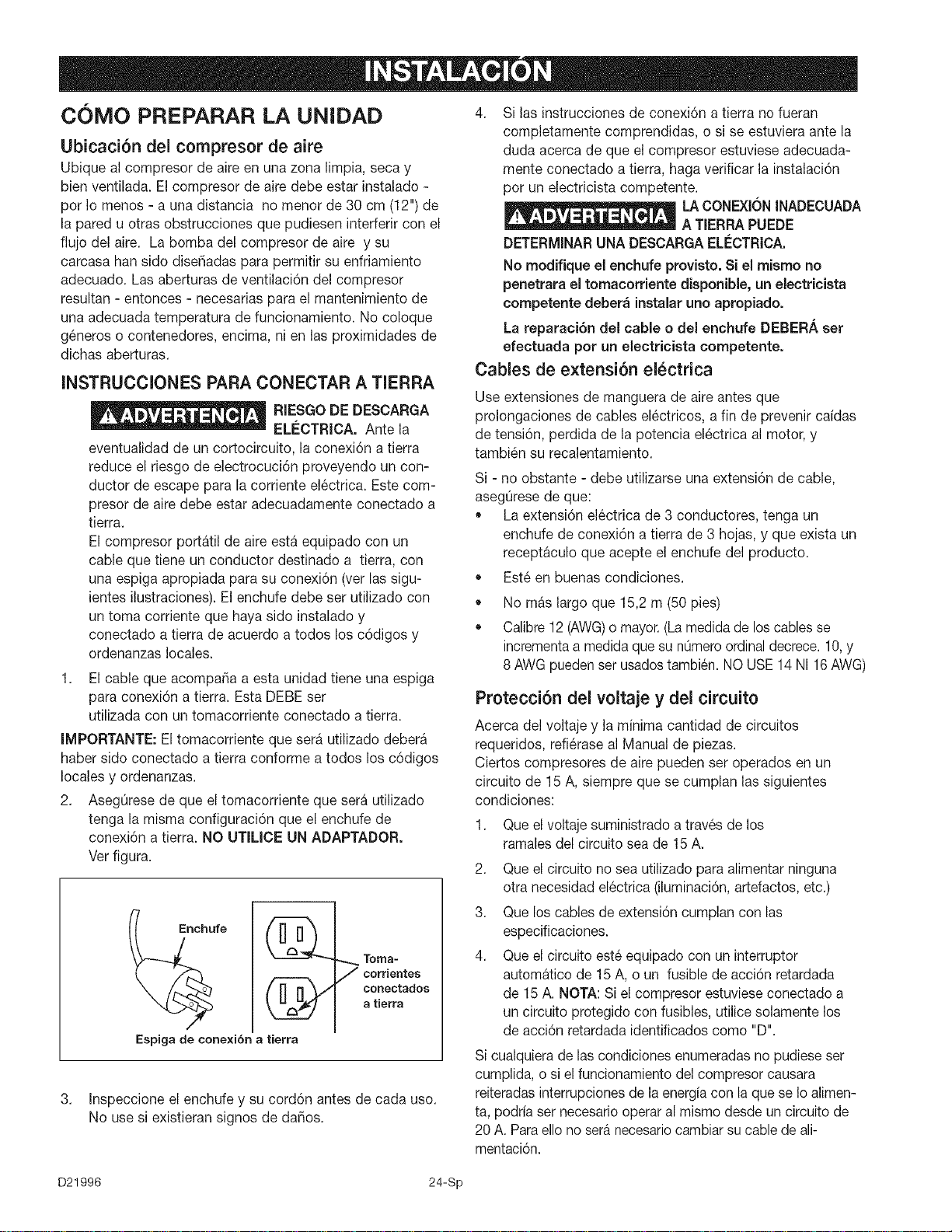
Instale un bul6n de tope y una tuerca por cada
rueda. Ajuste firmemente. El equipo se asentarA
en forma nivelada si las ruedas estAn instaladas
adecuadamente.
\\
\\
Rueda
Tuerca
Bul6n de tope
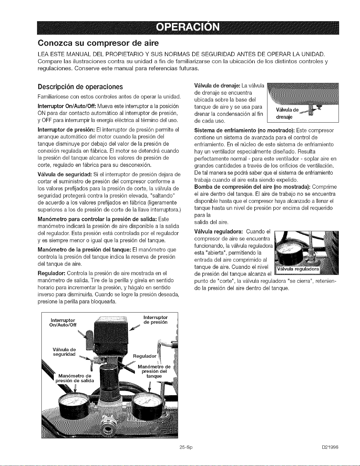
Limpie y seque el lado inferior de la pata del
tanque de aire que enfrenta alas ruedas. Extraiga
la cinta protectora adhesiva que cubre los pies de
rebote moldeados. Coloque los rebotes de los
pies en el extremo de cada pata. Presione firm
mente para pegarlos en su sitio.
Ser_ necesario sujetar o
soportar un lade del equipo
cuando se instalen las ruedas porque el compre=
sor tendr_ tendencia a volcarse.
23-Sp D21996
COMO PREPARAR LA UNIDAD
Ubicaci6n del compresor de aire
Ubique al compresor de aire en una zona limpia, secay
bien ventilada. El compresor de aire debe estar instalado -
por Io menos - a una distancia no menor de 30 cm (12") de
la pared u otras obstrucciones que pudiesen interferir con el
fiujo del aire. La bomba del compresor de aire y su
carcasa hart side diseSadas para permitir su enfriamiento
adecuado. Las aberturas de ventilaci6n del compresor
resultan - entonces - necesarias para el mantenimiento de
una adecuada temperatura de funcionamiento. No coloque
g6neros o contenedores, encima, ni en las proximidades de
dichas aberturas.
INSTRUCCIONES PARA CONECTAR A TIERRA
RIESGODEDESCARGA
ELI_CTRICA. Ante la
eventualidad de un cortocircuito, la conexi6n a tierra
reduce el riesgo de electrocuci6n proveyendo un con-
ductor de escape para la corriente el6ctrica. Este com-
presor de aire debe estar adecuadamente conectado a
tierra.
El compresor portatil de aire esta equipado con un
cable que tiene un conductor destinado a tierra, con
una espiga apropiada para su conexi6n (verlas sigu-
ientes ilustraciones). El enchufe debe set utilizado con
un toma corriente que haya sido instalado y
conectado a tierra de acuerdo a todos los c6digos y
ordenanzas locales.
1. El cable que acompaSa a estaunidad tiene una espiga
para conexi6n a tierra. Esta DEBEser
utilizada con un tomacorriente conectado a tierra.
IMPORTANTE: El tomacorriente que sera utilizado debera
haber side conectado a tierra conforme a todos los c6digos
locales y ordenanzas.
2. AsegOresede que el tomacorriente que sera utilizado
tenga la misma configuraci6n que el enchufe de
conexi6n a tierra. NO UTILICE UN ADAPTADOR.
Verfigura.
Espiga de cone×ibn a tierra
Toma-
7 corrientes
conectados
a tierra
3. Inspeccione el enchufe y su cord6n antes de cada uso.
No usesi existieran signos de daSos.
4. Si las instrucciones de conexi6n a tierra no fueran
completamente comprendidas, o si se estuviera ante la
duda acerca de que el compresor estuviese adecuada-
mente conectado a tierra, haga verificar la instalaci6n
por un electricista competente.
LA CONEXIONINADECUADA
A TIERRA PUEDE
DETERMINARUNA DESCARGAEL_:CTRICA.
No modifique el enchufe provisto. Si el mismo no
penetrara el tomacorriente disponible, un electricista
competente deber_ instalaruno apropiado.
La reparaci6n del cable o del enchufe DEBERA set
efectuada por un electricista competente.
Cables de extensi6n el_ctrica
Use extensiones de manguera de aire antes que
prolongaciones de cables el6ctricos, a fin de prevenir caidas
de tensi6n, perdida de la potencia el6ctrica al motor,y
tambi6n su recalentamiento.
Si - no obstante - debe utilizarse una extensi6n de cable,
asegQresede que:
La extensi6n el6ctrica de 3 conductores, tenga un
enchufe de conexi6n a tierra de 3 hojas, y que exista un
receptaculo que acepte el enchufe del producto.
Est6 en buenas condiciones.
®
®
No mas largo que I5,2 m (50 pies)
Calibre12 (AWG)o mayor.(Lamedidade loscables se
incrementaa medidaque su nOmeroordinaldecrece.10,y
8 AWGpuedenser usadostambi6n. NOUSE14 N116AWG)
Protecci6n del voitaje y dei circuito
Acerca del voltajey la minima cantidad de circuitos
requeridos, refi@aseal Manual de piezas.
Ciertos compresores de aire pueden ser operados en un
circuito de 15 A, siempre que se cumplan las siguientes
condiciones:
1. Que el voltaje suministrado a trav6s de los
ramales del circuito seade 15 A.
2. Que el circuito no sea utilizado para alimentar ninguna
otra necesidad el6ctrica(iluminaci6n,artefactos, etc.)
3. Que loscables de extensi6n cumplan con las
especificaciones.
4. Que el circuito est6 equipado con un interruptor
automatico de 15 A, o un fusible de acci6n retardada
de I5 A. NOTA:Si el compresor estuviese conectado a
un circuito protegido con fusibles, utilice solamente los
de acci6n retardadaidentificados como "D".
Si cualquierade lascondiciones enumeradasno pudieseser
cumplida, o si el funcionamiento del compresor causara
reiteradasinterrupcionesde laenergia con la que se Ioalimen-
ta, podria ser necesariooperaral mismodesde un circuito de
20 A. Paraello no ser_necesariocambiarsu cablede all-
mentaci6n.
D21996 24-Sp
Conozca su compresor de aire
LEA ESTE MANUAL DEL PROPIETARIO Y SUS NORMAS DE SEGURIDAD ANTES DE OPERAR LA UNIDAD.
Compare las ilustraciones contra su unidad a fin de familiarizarse con la ubicaci6n de los distintos controles y
regulaciones. Conserve este manual para referencias futuras.
Descripci6n de operaciones
Familiaricese con estos controles antes de operar la unidad.
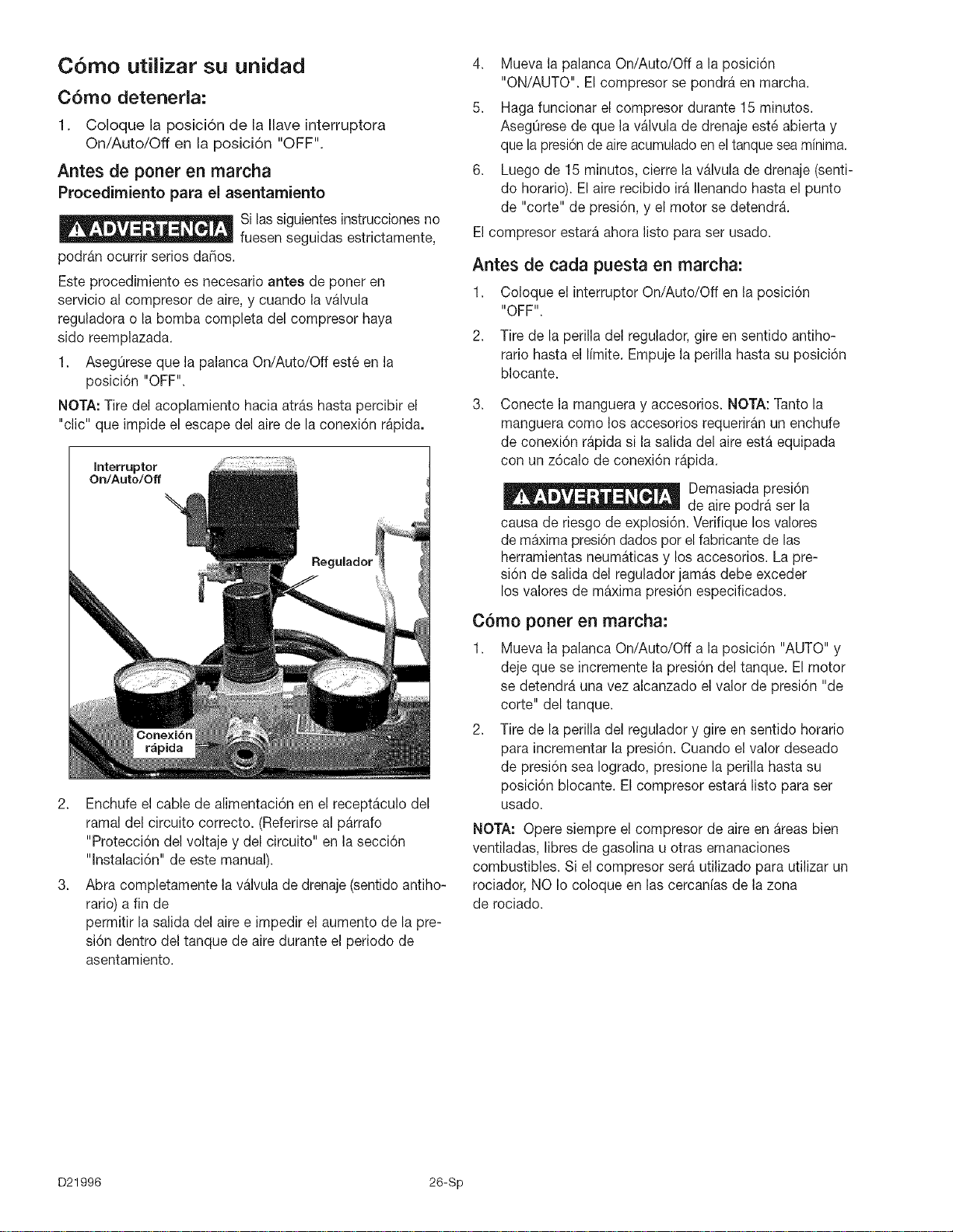
Interruptor On/Auto/Off: Mueva este interruptora la posici6n
ON para dar contacto automatico al interruptor de presi6n,
y OFFpara interrumpir la energiael6ctricaal t6rmino del uso.
Interruptor de presi6n: El interrupter de presi6n permite el
arranque automatico del motor cuando la presi6n del
tanque disminuye por debajo delvalor de la presi6n de
conexi6n regulada en fabrica. El motor se detendra cuando
la presi6n del tanque alcance los valores de presi6n de
corte, regulado enfabrica parasu desconexi6n.
Wlvula de seguridad: Si el interruptor de presi6n dejarade
cortar el suministro de presi6n del compresor conforme a
los valores prefijados para la presi6n de corte, la valvula de
seguridad protegera contra la presi6n elevada, "saltando"
de acuerdo a los valores prefijados en fabrica (ligeramente
superiores a los de presi6n de corte de la Ilave interruptora.)
Man6metro para controlar la presi6n de salida: Este
man6metro indicara la presi6n de aire disponible a la salida
del regulador. Esta presi6n esta controlada por el regulador
yes siempre menor o igual que la presi6n del tanque.
Man6metro de la presi6n del tanque: El man6metro que
controla la presi6n del tanque indica la reserva de presi6n
del tanque de aire.
Regulador: Controla lapresi6n de aire mostrada en el
man6metro de salida. Tire de la perilla y girela ensentido
horario para incrementar la presi6n, y hagalo en sentido
inverso paradisminuirla.Cuandose Iogrela presi6ndeseada,
presionela perilla parabloquearla.
V_lvula de drenaje: Lavalvula
de drenaje se encuentra
ubicada sobre la base del
tanque de airey se usa para
drenar la condensaci6n al fin
de cada uso.
Valvulade
drenaje
Sistema de enfriamiento (no mostrado): Este compresor
contiene un sistema de avanzada para el control de
enfriamiento. En el nOcleode este sistema de enfriamiento
hay un ventilador especialmente dise_iado. Resulta
perfectamente normal - para este ventilador - soplar aire en
grandes cantidades a trav6s de los orificios de ventilaci6n.
Detal manerasepodra saberque elsistema de enfriamiento
trabaja cuando el aire esta siendo expelido.
Bomba de compresi6n del aire (no mostrada): Comprime
el aire dentro del tanque. El aire de trabajo no se encuentra
disponible hastaque el compresor hayaalcanzadoa Ilenarel
tanque hasta un nivel de presi6n pot encima del requerido
para la
salida del aire.
V_lvula reguladora: Cuando el
compresor de aire se encuentra
funcionando, la valvulareguladora
esta "abierta",permitiendo la
entrada del aire comprimido al
tanque de aire.Cuando el nivel V_lvula reguladora
de presi6n del tanque alcanza el
punto de "corte", la valvula reguladora "se cierra", retenien-
do la presi6n del aire dentro del tanque.
Interruptor
Interruptor de presi6n
On/Auto/Off f
Regulador
25-Sp D21996
C6mo utilizar su unidad
C6mo detenerla:
1. Coloque la posici6n de la Ilave interruptora
On/Auto/Off en la posicidn "OFF".
Antes de poner en marcha
Procedimiento para el asentarniento
Si lassiguientesinstruccionesno
fuesen seguidas estrictamente,
podran ocurrir serios da[qos.
Este procedimiento es necesario antes de poner en
servicio al compresor de aire,y cuando la valvula
reguladora o labomba completa del compresor haya
sido reemplazada.
I. AsegOreseque la palanca On/Auto/Off est6 en la
posicidn "OFF".
NOTA: Tiredel acoplamiento hacia atras hastapercibir el
"clic" que impide el escape del airede la conexi6n rapida.
interruptor
On/Auto/Off
,q
r_pida
Regulador
2. Enchufe elcable de alimentaci6n en elreceptaculo del
ramal del circuito correcto. (Referirseal parrafo
"Protecci6n del voltaje y del circuito" en lasecci6n
"lnstalaci6n" de este manual).
3. Abra completamente la valvulade drenaje(sentido antiho-
rario) a fin de
permitir la salida del aire e impedir el aumento de la pre-
si6n dentro del tanque de aire durante el periodo de
asentamiento.
4. Mueva la palanca On/Auto/Off a la posici6n
"ON/AUTO". El compresor se pondra en marcha.
5. Haga funcionar el compresor durante 15 minutos.
AsegOresede que la valvula de drenaje est6 abierta y
que la presi6nde aireacumuladoen el tanqueseaminima.
6. Luego de 15minutos, cierre la valvula de drenaje (senti-
do horario).El aire recibido ira Ilenandohasta el punto
de "corte" de presi6n, y el motor se detendra.
Elcompresor estara ahora listo para ser usado.
Antes de cada puesta en marcha:
I. Coloque el interruptor On/Auto/Off en la posici6n
"OFF".
2. Tire de la perilla del regulador, gire en sentido antiho-
rario hasta ellimite. Empuje la perilla hasta su posici6n
blocante.
3.
Conecte la mangueray accesorios. NOTA: Tanto la
manguera como los accesorios requeriran un enchufe
de conexi6n rapida si la salida del aireesta equipada
con un z6calo de conexi6n rapida.
Demasiada presi6n
de aire podra ser la
causa de riesgo de explosi6n. Verifique los valores
de maximapresi6ndadospor elfabricantede las
herramientas neum_ticas y los accesorios. La pre-
si6n de salida del regulador jamas debe exceder
los valores de maxima presi6n especificados.
C6mo porter en marcha:
I. Mueva la palanca On/Auto/Off a la posici6n "AUTO" y
deje que se incremente la presi6n del tanque. El motor
se detendra una vez alcanzado el valor de presi6n "de
corte" del tanque.
2. Tire de la perilla del regulador y gire en sentido horario
para incrementar la presi6n. Cuando el valor deseado
de presi6n sea Iogrado, presione la perilla hasta su
posici6n blocante. El compresor estara listo para ser
usado.
NOTA: Opere siempre el compresor de aire en areasbien
ventiladas, libres de gasolina u otras emanaciones
combustibles. Si el compresor sera utilizado para utilizar un
rociador, NO Io coloque en las cercanias de la zona
de rociado.
D21996 26-Sp
Responsabilidades del cliente
Antes de cada Diariamente o
luego de
uso cada uso
Verifique la v6.1vula
de sequridad •
Drenaje del tanque •
NOTA: Vea en la secci6n "Operaci6n" la ubicaci6n de los
controles.
C6mo verificar la v_lvula de seguridad
Si la valvula de seguri-
dad no trabaja ade-
cuadamente, ello podra determinar la sobrepresi6n del
tanque, creando elriesgo de su ruptura o explosi6n.
Antes de poner en marcha el motor, tire del anillo de la
valvula de seguridad para confirmar la seguridad de que
la misma opera libremente, si la valvula quedase trabada
o no trabajara c6modamente, debera ser reemplazada
por el mismo tipo de valvula.
C6mo drenar el tanque
1. Coloque la palanca On/Auto/Off en laposici6n "OFF".
2. Tire de la perilladel regulador y gire en sentido horario para
establecer la salida de presi6n en cero.
3. Remueva laherramienta neum_tica o el accesorio.
4. Tire del arode la valvula de seguridad dejando purgar el aire
del tanque hasta que este reduzca su presi6n aproximada-
mente a 20 PSi. Suelte el aro de la valvula de seguridad.
5. Dreneel agua contenida en eltanque de aire,abriendo la
valvula de drenaje ubicada en la base del tanque (en sentido
contrario alas agujas de reloj).
El agua se condensa
dentro del tanque de
aire. Si no se drena, ella corroer_ debilitando las paredes
del tanque de aire, originando un riesgo de ruptura.
6. Una vez drenada el agua, cierre la valvula de drenaje (giran-
do en sentido horario). Ahora el compresor de aire podra ser
guardado.
NOTA: Si la valvula de drenaje fuera del tipo enchufe, elimine toda
la presi6n de aire. La valvula podr_ entonces ser extraida, limpiada
y finalmente reinstalada.
27-Sp D21996
_La unidad cicla automAticamente en cuanto la energia el_ctrica es conectada. AI efec-
tuar el mantenimiento, usted quedarA expuesto a tensi6n viva, aire comprimido o partes en movimiento. Debido
a tales circunstancias, podrian ocurrirle lesiones personales. Antes de efectuar mantenimiento o reparaci6n algu-
na, desenchufe el compresor y purgue cualquier presi6n de aire.
TODO TIPO DE MANTENIMIENTO Y OPERACIONES DE REPARACION NO MENCIONADOS,
DEBERAN SER EFECTUADOS POR PERSONAL T_:CNICO ESPECIALIZADO.
Antes de dar servicio:
• Desenchufe o desconecte el suministro
el6ctrico al compresor de aire.
Purgue la presi6n del tanque.
Deje enfriar al compresor de aire.
Para reemplazar o limpiar la v_lvulareguladora
I. Libere toda presi6n de aire del tanque. Yea "Drenajedel
tanque" en la secci6n mantenimiento.
2. Desenchufe el equipo.
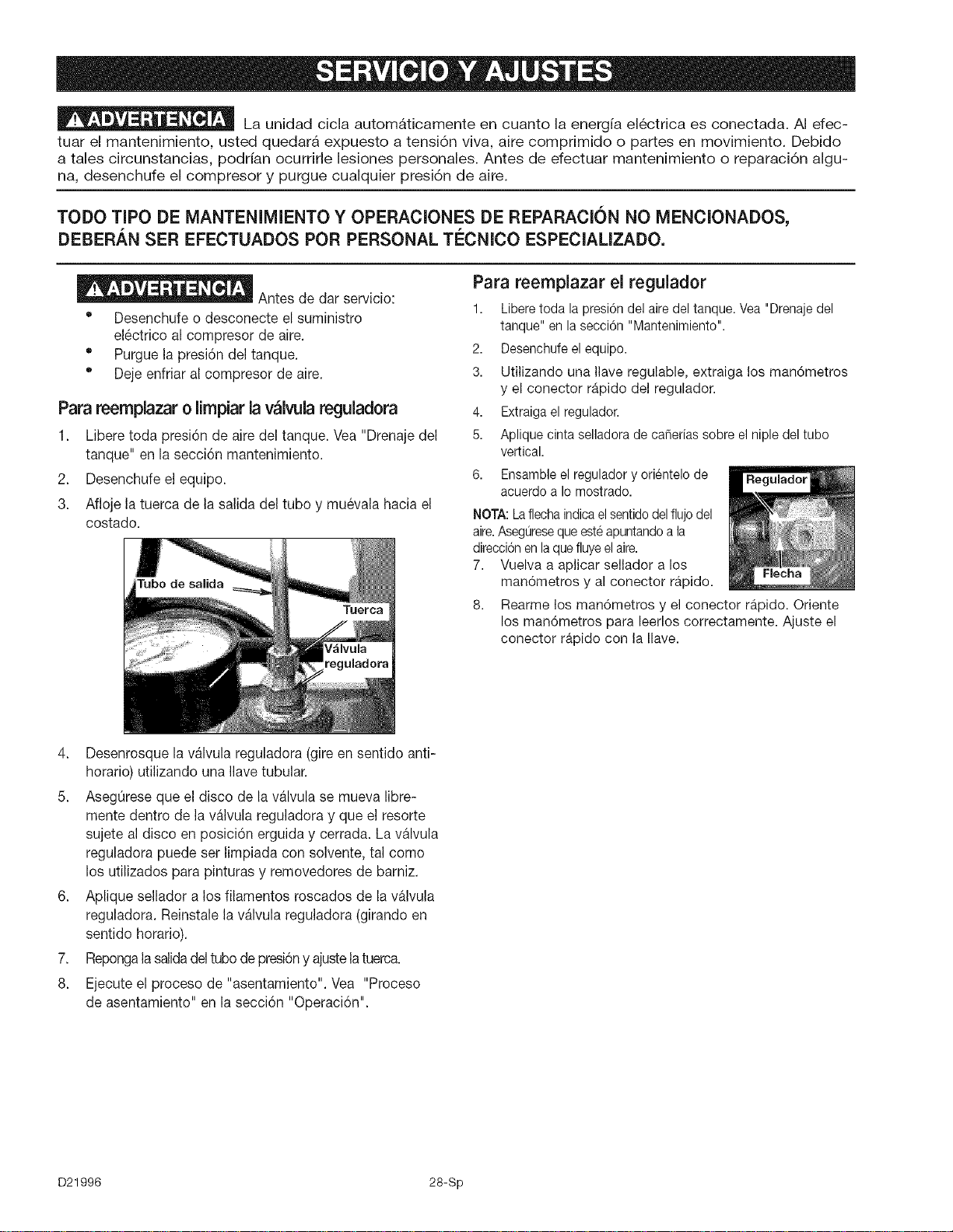
3. Afloje la tuerca de lasalida del tubo y mu6vala hacia el
costado.
Para reemplazar el regulador
1. Liberetedala presi6ndelairedel tanque.Vea"Drenajedel
tanque"enlasecci6n"Mantenimiento".
2. Desenchufeelequipo.
3. Utilizando una Ilave regulable,extraiga los man6metros
y el conector rapido del regulador.
4. Extraigael regulader.
5. Apliquecintaselladorade caSeriassebreelnipledeltube
vertical.
6. Ensambleelreguladoryorientelode Regulador
acuerdoa Iomostrado.
NOTA:Laflechaindicaelsentidodelflujodel
aire.Aseguresequeesteapuntandoala
direcci6nenlaquefluyeelaire.
7. Vuelvaa aplicar sellador a los
man6metros y al conector rapido.
8.
Rearme los man6metros y el conector rapido. Oriente
los man6metros para leerlos correctamente. Ajuste el
conector rapido con la Ilave.
4. Desenrosque la valvula reguladora(gire en sentido anti-
horario) utilizando una Ilavetubular.
5. AsegQreseque eldisco de la valvula se mueva libre-
mente dentro de la valvula reguladoray que el resorte
sujete al disco en posici6n erguida y cerrada. Lavalvula
reguladora puede ser limpiada con solvente, tal como
los utilizados para pinturas y removedores de barniz.
6. Aplique sellador a los filamentos roscados de la valvula
reguladora. Reinstale la valvula reguladora (girando en
sentido horario).
7. Repongalasalidadeltubodepresi6ny ajustelatuerca.
8. Ejecute el proceso de "asentamiento". Vea "Proceso
de asentamiento" en la secci6n "Operaci6n".
D21996 28-Sp
Antes de guardar su compresor de aire, asegOrese de
hacer Io siguiente:
1. Revise la secci6n "Mantenimiento" de las pAginas
precedentes y ejecute el mantenimiento progra-
mado de acuerdo a la necesidad.
2. Coloque la palanca On/Auto/Off en la posicidn
"OFF".
3. Gire el regulador en sentido antihorario y fije la
presi6n de salida en cero.
4. Extraiga la herramienta neumAtica o el accesorio.
5. Tire del anillo de la vAIvula de seguridad permi-
tiendo el purgado del aire del tanque hasta que la
presi6n del mismo Ilegue aproximadamente a 20
PSI. Suelte el anillo de la v&lvula de seguridad.
6. Drene el agua del tanque de aire abriendo la
vAIvula de drenaje ubicada en el rondo del
tanque.
El agua se conden-
sa dentro del
tanque de aJre. Si no se drena, ella corroerA
debilitando la paredes del tanque de aire,
originando un riesgo de ruptura de sus pare-
des.
7.Una vez que el agua haya sido drenada,
cierre la vAIvula de drenaje.
NOTA: Si la vAIvula de drenaje estuviese enchufada,
libere toda la presidn de aire. La vAIvula podr& ser
extraida, limpiada y luego reinstalada.
8. Proteja el cable el6ctrico y las mangueras de aire
de daSos (tales como ser pisoteados o pasados
por encima). Enrdllelos en forma floja, alrededor
de la manija del compresor. (Si asi estuviese
equipado).
Almacene el compresor de aire en un sitio limpio y seco.
29-Sp D21996
El desarrollo de reparaciones puede exponer a sitios con corriente viva, partes en
movimiento o fuentes de aire comprimido que podrian ocasionar lesiones personales.
Antes de intentar reparaci6n alguna, desenchufe el compresor de aire y purgue toda la presi6n de aire del tanque.
CAUSA CORRECCION
PROBLEMA
Presi6n excesiva del tanque - la
valvula de seguridad se dispara.
Las conexiones pierden aire
P6rdida de aire en el tanque de aire o
en las soldaduras del tanque de aire.
P6rdida de aire entre el cabezal y el
plato de valvula.
La lectura de la presi6n en el
man6metro del reguladorde presi6n
baja cuando se usa un accesorio.
P6rdida de aire enla valvula de
seguridad.
El interruptor de presi6n no
interrumpe al motor cuando el
compresor alcanza la presi6n "de
corte".
El interruptor de presi6n "de corte"
esta calibrado demasiado alto.
Las conexiones de los tubos no estan
suficientemente ajustadas
Tanquede aire defectuoso.
P6rdida en el sellado.
Esnormal que ocurran "algunas"
cddas de presi6n
Posible defecto en lavalvula de
seguridad.
Mueva la palanca On/Auto/Off a la
posici6n "OFF", si el equipo no corta,
contacte a un t6cnico calificado para
el servicio.
Contacte a un t6cnico de servicio
calificado.
Ajuste las conexiones en las que el
aire puede set escuchado
escapandose.Verifique las conexiones
con soluci6n jabonosa y agua. NO
SOBREAJUSTE.
Eltanquede airedebeser reemplazado.
No reparela perdida.
No efectOeperforaci6n alguna sobre
la soldadura o cosa semejante sobre
el tanque de aire, ello Io debilitara. El
tanque podrfa romperse o explotar.
Contacte un t6cnico calificado de
servicio.
Si existe una excesiva caida de
presi6n cuando se utiliza el
accesorio,ajuste el reguladorsiguiendo
lasinstruccionesdadas en la pagina6.
NOTA:Ajuste la presi6n regulada bajo
condiciones de flujo (mientras el
accesorio esta siendo usado).
Opere la valvula de seguridad manual-
mente tirando de su anillo. Si la valvula
aun pierde, debera set reemplazada.
D21996 30-Sp
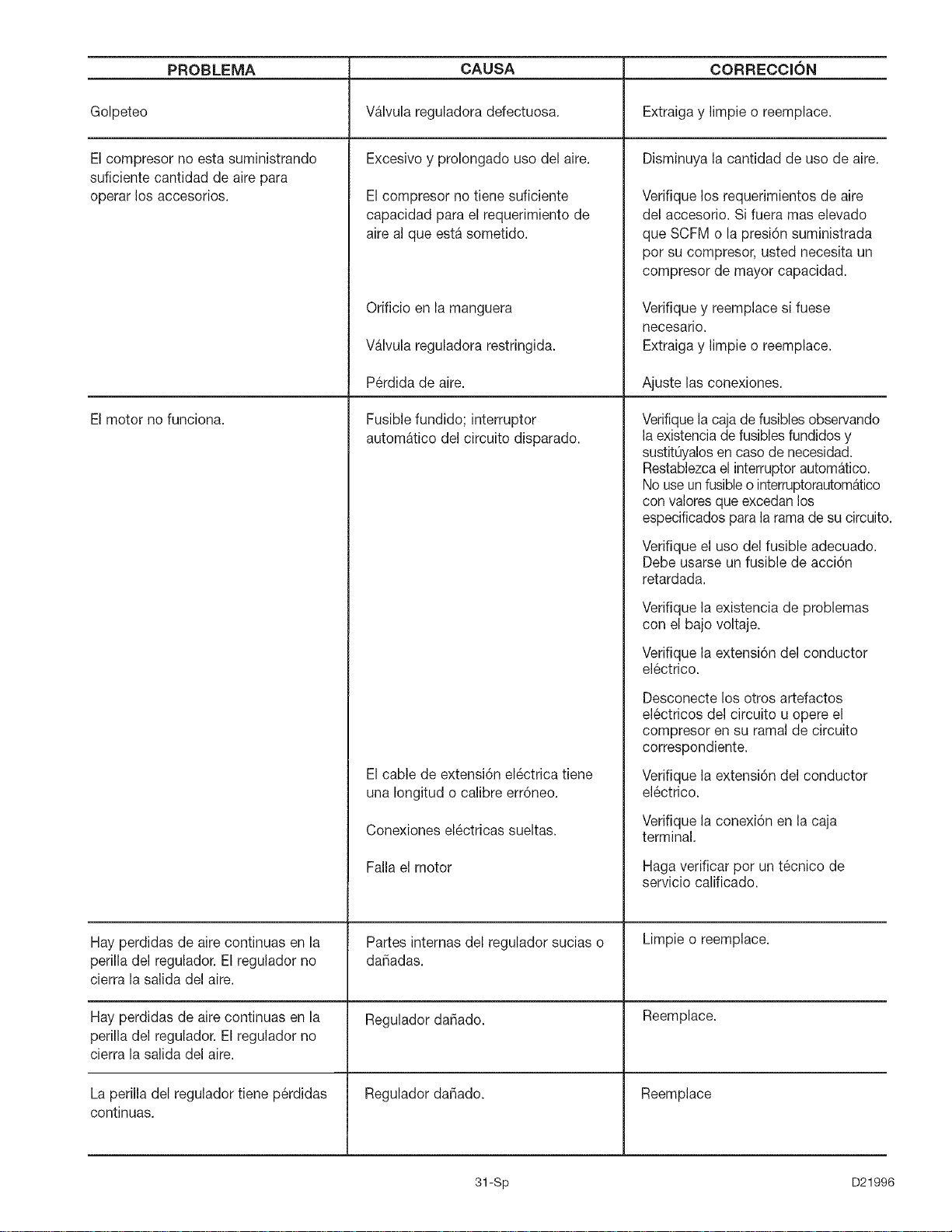
PROBLEMA CAUSA CORRECClON
Golpeteo Valvula reguladora defectuosa. Extraiga y limpie o reemplace.
Excesivo y prolongado uso del aire. Disminuya la cantidad de uso de aire.
El compresor no tiene suficiente
capacidad para el requerimientode
aire al que estasometido.
El compresor no esta suministrando
suficiente cantidad de aire para
operar los accesorios.
El motor no funciona.
Hay perdidas de aire continuas en la
perilla del regulador. El regulador no
cierra la salida del aire.
Hay perdidas de aire continuas en la
perilla del regulador. El regulador no
cierra la salida del aire.
La perilla del reguladortiene p@didas
continuas.
Orificio en la manguera
Valvula reguladora restringida.
P@didade aire.
Fusible fundido; interruptor
automatico del circuito disparado.
El cable de extensi6n electrica tiene
una Iongitud o calibre err6neo.
Conexiones el6ctricas sueltas.
Falla el motor
Partes internas del regulador sucias o
dafiadas.
Regulador da_ado.
Reguladorda_iado.
Verifique los requerimientos de aire
del accesorio. Sifuera mas elevado
que SCFM o lapresi6n suministrada
por su compresor, usted necesita un
compresor de mayor capacidad.
Verifique y reemplace si fuese
necesario.
Extraiga y limpie o reemplace.
Ajuste las conexiones.
Verifiquela cajadefusiblesobservando
la existenciade fusiblesfundidos y
sustitQyalosen caso de necesidad.
Restablezcael interruptorautomatico.
Nouseunfusibleo interruptorautom_tico
convaloresque excedanlos
especificadospara la ramade su circuito.
Verifique el uso del fusible adecuado.
Debe usarse un fusible de acci6n
retardada.
Verifique la existencia de problemas
con el bajo voltaje.
Verifique la extensi6n del conductor
el6ctrico.
Desconecte los otros artefactos
el6ctricos del circuito u opere el
compresor en su ramal de circuito
correspondiente.
Verifique la extensi6n del conductor
el6ctrico.
Verifique la conexi6n en la caja
terminal.
Haga verificar por un t6cnico de
servicio calificado.
Limpie o reemplace.
Reemplace.
Reemplace
31-Sp D21996
For repair of major brand appliances in your own home...
iiiiiiiiiiiiiiiii_
no matter who made it, no matter who sold it!
iiiiiiiiiiiiiiii
1-800-4-MY-HO_IIIE SMAnytime, day or night
iiiiiiiiiiiiiiii
www.sears.com
TObring in products such as vacuums, lawn equipment and electronics
iiiiiiii,or repair, call for the location of your nearest Sears Parts & Repair Center.
iiiiiiiiiiHHH
iiiiiiii _-8oo-488-1222 Anytime, day or night
www.sears.com
For the replacement parts, accessories and owner's manuals
that you need to do-it-yourself, call Sears PartsDirect SM,
1--800 366-PART 6 a.m.- 11 p.m.CST,
(1=800=366=7278) 7 days a week
www.sears.com/partsdirect
To purchase or inquire1800about827t6655SearsService Agreement:
7 a.m.- 5 p.m. CST, Mon.- Sat.
Pare pedir servicio de reparaci6n a domicilio, Au Canada pour service en frangais:
y para ordenar piezas con entrega a domicilio: 1 =877=LE=FOYER sM
1-888-SU-HOGAR sM 1 877 533 6937
( - _ _ )
(1-888-784-6427)
© Sears, Roebuck and Co.
(_ Registered Trademark / TMTrademark of Sears, Roebuck and Co.
(¢ Marca Registrada / T_4Mama de F_tbrica de Sears, Roebuck and Co.
D21996 32-Eng