ASSEMBLY MANUAL / OWNER’S MANUAL
Manual en Español Latino Americano:
http://www.schwinntness.com
430

2
Important Safety Instructions 3
Safety Warning Labels / Serial Number 5
Specications 6
Before Assembly 6
Parts 7
Hardware 8
Tools 8
Assembly 9
Moving the Machine 21
Leveling the Machine 21
Features 22
Console Features 23
Operations 28
Adjustments 28
Power Up / Idle Mode 29
Quick Start Program 30
User Proles 30
Pausing or Stopping 34
Results / Cool Down Mode 35
GOAL TRACK Statistics 35
Console Service Mode 37
Maintenance 38
Maintenance Parts 39
Troubleshooting 40
Warranty 43
Nautilus, Inc., (800) NAUTILUS / (800) 628-8458, www.NautilusInc.com - Customer Service: North America (800) 605-3369,
[email protected] | outside U.S. +01-360-859-5180, [email protected] | Printed in China | © 2016 Nautilus, Inc. | ®
indicates trademarks registered in the United States. These marks may be registered in other nations or otherwise protected
by common law. Schwinn, the Schwinn Quality logo, Schwinn 430, Schwinn Connect, Bowex, Nautilus, and Universal are
trademarks owned by or licensed to Nautilus, Inc. MyFitnessPal
®
and Loctite
®
are trademarks of their respective owners.
TABLE OF CONTENTS
To validate warranty support, keep the original proof of purchase and record the following information:
Serial Number __________________________
Date of Purchase __________________________
To register your product warranty , go to: www.SchwinnFitness.com/register
Or call 1 (800) 605–3369.
If you have questions or problems with your product, please call 1 (800) NAUTILUS (628–8458).

3
IMPORTANT SAFETY INSTRUCTIONS
This icon means a potentially hazardous situation which, if not avoided, could result in death or serious
injury.
Obey the following warnings:
Read and understand all warnings on this machine.
Carefully read and understand the Assembly instructions. Read and understand the complete
Manual. Keep the Manual for future reference.
To reduce the risk of electrical shock or unsupervised usage of the equipment, always unplug this
machine from the electrical outlet immediately after using and before cleaning.
• Keep bystanders and children away from the product you are assembling at all times.
• Do not connect power supply to the machine until instructed to do so.
• The machine should never be left unattended when plugged in. Unplug from outlet when not in use, and before putting
on or taking off parts.
• Before each use, examine the machine for damage to power cord, loose parts or signs of wear. Do not use if found in
this condition. Contact Nautilus Customer Service for repair information.
• Do not drop or put objects into any opening of the machine.
• Do not assemble this machine outdoors or in a wet or moist location.
• Make sure assembly is done in an appropriate work space away from foot trafc and exposure to bystanders.
• Some components of the machine can be heavy or awkward. Use a second person when doing the assembly steps
involving these parts. Do not do steps that involve heavy lifting or awkward movements on your own.
• Set up this machine on a solid, level, horizontal surface.
• Do not try to change the design or functionality of this machine. This could compromise the safety of this machine and
will void the warranty.
• If replacement parts are necessary, use only genuine Nautilus replacement parts and hardware. Failure to use
genuine replacement parts can cause a risk to users, keep the machine from operating correctly and void the
warranty.
• Do not use until the machine has been fully assembled and inspected for correct performance in accordance with the
Manual.
• Use this machine only for its intended use as described in this manual. Do not use attachments not recommended by
the manufacturer.
• Do all assembly steps in the sequence given. Incorrect assembly can lead to injury or incorrect function.
• Silicone lubricant is not intended for human consumption. Keep out of reach of children. Store in a safe place.
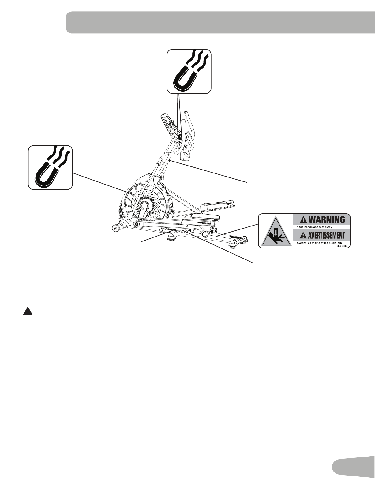
• This product contains magnets. Magnetic elds can interfere with the normal use of certain medical devices at a close
range. Users may come into proximity of the magnets in the assembly, maintenance, and/or use of the product. Given
the obvious importance of these devices, such as a pacemaker, it is important that you consult with your medical
provider in connection with the use of this equipment. Please consult the “Safety Warning Labels and Serial Number”
section to determine the location of the magnets on this product.
• SAVE THESE INSTRUCTIONS.

4
This icon means a potentially hazardous situation which, if not avoided, could result in death or serious
injury.
Before using this equipment, obey the following warnings:
Read and understand the complete Manual. Keep the Manual for future reference.
Read and understand all warnings on this machine. If at any time the Warning labels become loose,
unreadable or dislodged, contact Nautilus Customer Service for replacement labels.
• Children must not be let on or near to this machine. Moving parts and other features of the machine can be dangerous
to children.
• Not intended for use by anyone under 14 years of age.
• Consult a physician before you start an exercise program. Stop exercising if you feel pain or tightness in your
chest, become short of breath, or feel faint. Contact your doctor before you use the machine again. Use the values
calculated or measured by the machine’s computer for reference purposes only.
• Before each use, examine this machine for loose parts or signs of wear. Do not use if found in this condition. Monitor
the Pedals and Crank Arms closely. Contact Nautilus Customer Service for repair information.
• Maximum user weight limit: 300 lbs. (136 kg). Do not use if you are over this weight.
• This machine is for home use only.
• Do not wear loose clothing or jewelry. This machine contains moving parts. Do not put ngers or other objects into
moving parts of the exercise equipment.
• Set up and operate this machine on a solid, level, horizontal surface.
• Make the Foot Pedals stable before you step on them. Use caution when you step on and off the machine.
• Disconnect all power before servicing this machine.
• Do not operate this machine outdoors or in moist or wet locations.
• Keep at least 24” (0.6 m) on each side of the machine clear. This is the recommended safe distance for access and
passage around and emergency dismounts from the machine. Keep third parties out of this space when machine is in
use.
• Do not over exert yourself during exercise. Operate the machine in the manner described in this manual.
• Correctly adjust and safely engage all Positional Adjustment Devices. Make sure that the Adjustment Devices do not
hit the user.
• Keep the Foot Pedals clean and dry.
• Exercise on this machine requires coordination and balance. Be sure to anticipate that changes in speed and
resistance level can occur during workouts, and be attentive in order to avoid loss of balance and possible injury.
• A machine should never be left unattended when plugged in. Unplug from outlet when not in use, and before putting
on or taking off parts.
• Prior to use, read and understand the owner’s manual. The appliance is not to be used by persons with functional
limitations and impairments, reduced physical, sensory or mental capabilities, or lack of experience and knowledge.
5
SAFETY WARNING LABELS AND SERIAL NUMBER
FCC Compliance
!
Changes or modications to this unit not expressly approved by the party responsible for compliance could
void the user’s authority to operate the equipment.
The machine and power supply comply with part 15 of the FCC rules. Operation is subject to the following two conditions:
(1) This device may not cause harmful interference, and (2) this device must accept any interference received, including
interference that may cause undesired operation.
Note: This machine and power supply have been tested and found to comply with the limits for a Class B digital
device, pursuant to Part 15 of the FCC Rules. These limits are designed to provide reasonable protection against
harmful interference in a residential installation. This equipment generates, uses and can radiate radio frequency
energy and, if not installed and used in accordance with the instructions, may cause harmful interference to radio
communications.
However, there is no guarantee that interference will not occur in a particular installation. If this equipment does cause
harmful interference to radio or television reception, which can be determined by turning the equipment off and on, the
user is encouraged to try to correct the interference by one or more of the following measures:
• Reorient or relocate the receiving antenna.
• Increase the separation between the equipment and receiver.
• Connect the equipment into an outlet on a circuit different from that to which the receiver is connected.
• Consult the dealer or an experienced radio/TV technician for help.
Serial Number
•
•
Product Specication
WARNING!
• Injury or death is possible if
caution is not used while using
this machine.
• Keep children and pets
away.
• Read and follow all warnings on
this machine.
• Refer to the Owner’s Manual for
additional warnings and safety
information.
• The heart rate displayed is an
approximation and should be
used for reference only.
• Not intended for use by anyone
under 14 years of age.
• The maximum user weight for this
machine is 300 lbs (136 kg).
• This machine is for home use
only.

6
SPECIFICATIONS
Before Assembly
Select the area where you are going to set up and operate your machine. For safe operation, the location must be on
a hard, level surface. Allow a workout area of a minimum 76.2” x 118.1” (193.4 cm x 300 cm). Be sure that the workout
space you are utilizing has adequate height clearance, taking into consideration the height of the user and the maximum
height of the pedals with the incline fully engaged.
Basic Assembly Tips
Follow these basic points when you assemble your machine:
• Read and understand the “Important Safety Instructions” before assembly.
• Collect all the pieces necessary for each assembly step.
• Using the recommended wrenches, turn the bolts and nuts to the right (clockwise) to tighten, and the left (counterclock-
wise) to loosen, unless instructed otherwise.
• When attaching 2 pieces, lightly lift and look through the bolt holes to help insert the bolt through the holes.
• The assembly can require 2 people.
Maximum User Weight: 300 lbs. (136 kg)
Max pedal height at full incline: 26.0” (66.1 cm)
Machine weight : 168.7 lbs (76.5 kg)
Power Requirements:
Operational Voltage: 9VDC
Operating Current: 1500 mA
Regulatory Approvals:
AC Power Adapter: UL listed, CSA certied (or equivalent),
Rated 120V 60Hz Input, 9VDC, 1500mA
Output. Class 2.
!
This product, its packaging, and components contain chemicals known to the State of
California to cause cancer, birth defects, or reproductive harm. This Notice is provided in
accordance with California’s Proposition 65. If you would like additional information,
please refer to our website at www.nautilus.com/prop65.
63.2”
(160.5 cm)
70.1”
(178.1 cm)
28.2”
(71.5 cm)
7
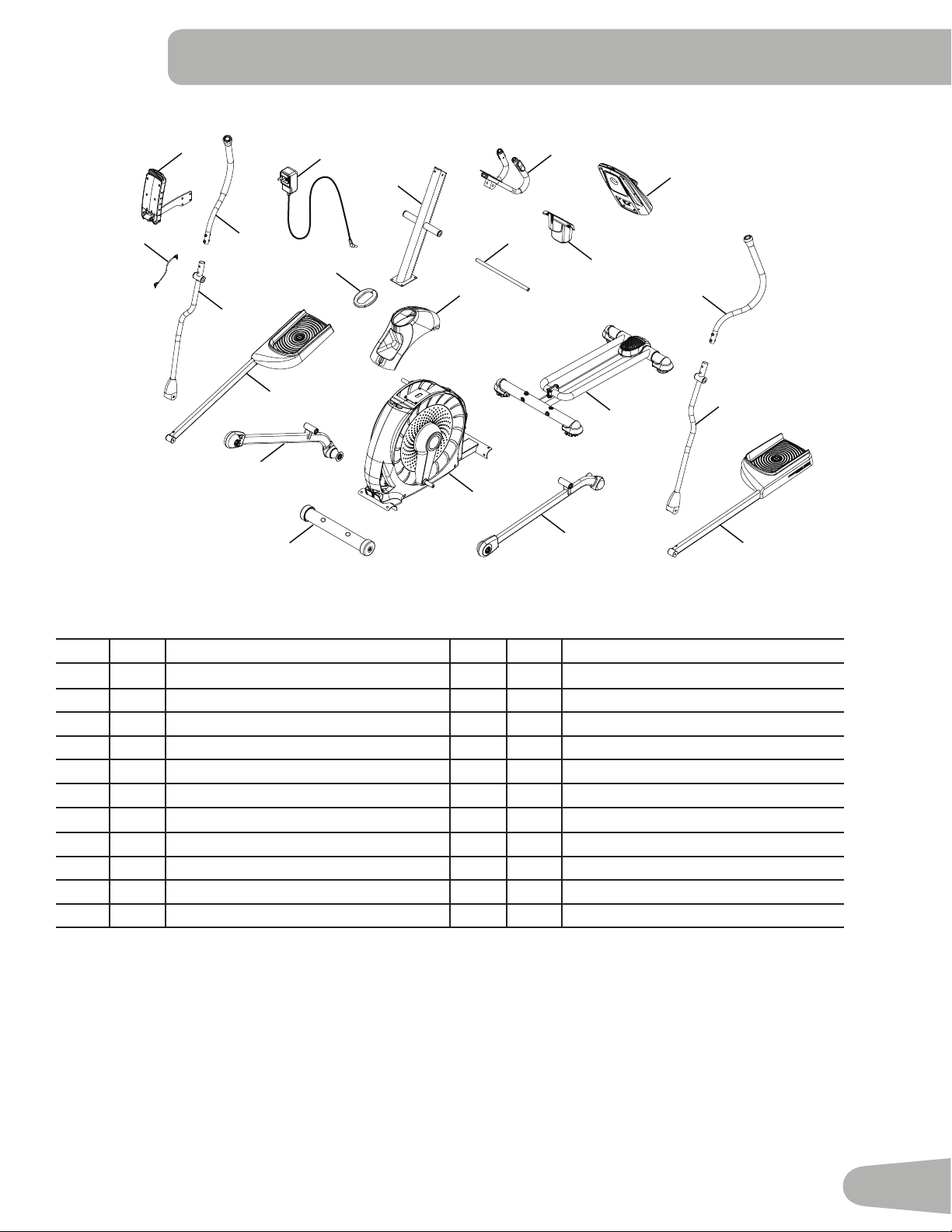
A decal has been applied to all right (“ R ”) and left (“ L ”) parts to assist with assembly.
Item Qty Description Item Qty Description
1 1 Console Mast 12 1 Upper Shroud
2 1 Static Handlebar 13 1 Front Stabilizer
3 1 Arm Pivot Rod 14 1 Right Leg
4 1 Water Bottle Holder 15 1 Right Pedal
5 1 Console 16 1 Shroud Cap
6 1 Upper Left Handlebar Arm 17 1 Lower Right Handlebar Arm
7 1 Lower Left Handlebar Arm 18 1 Upper Right Handlebar Arm
8 1 Left Pedal 19 1 AC Power Adapter
9 1 Rail Assembly 20 1 MP3 Cord
10 1 Left Leg 21 1 Manual Lift Assembly
11 1 Frame 22 1 Silicone Lubricant, Bottle (not shown)
PARTS
1
4
6
5
2
3
12
7
8
10
11
9
16
14
13
18
17
15
19
20
21
8
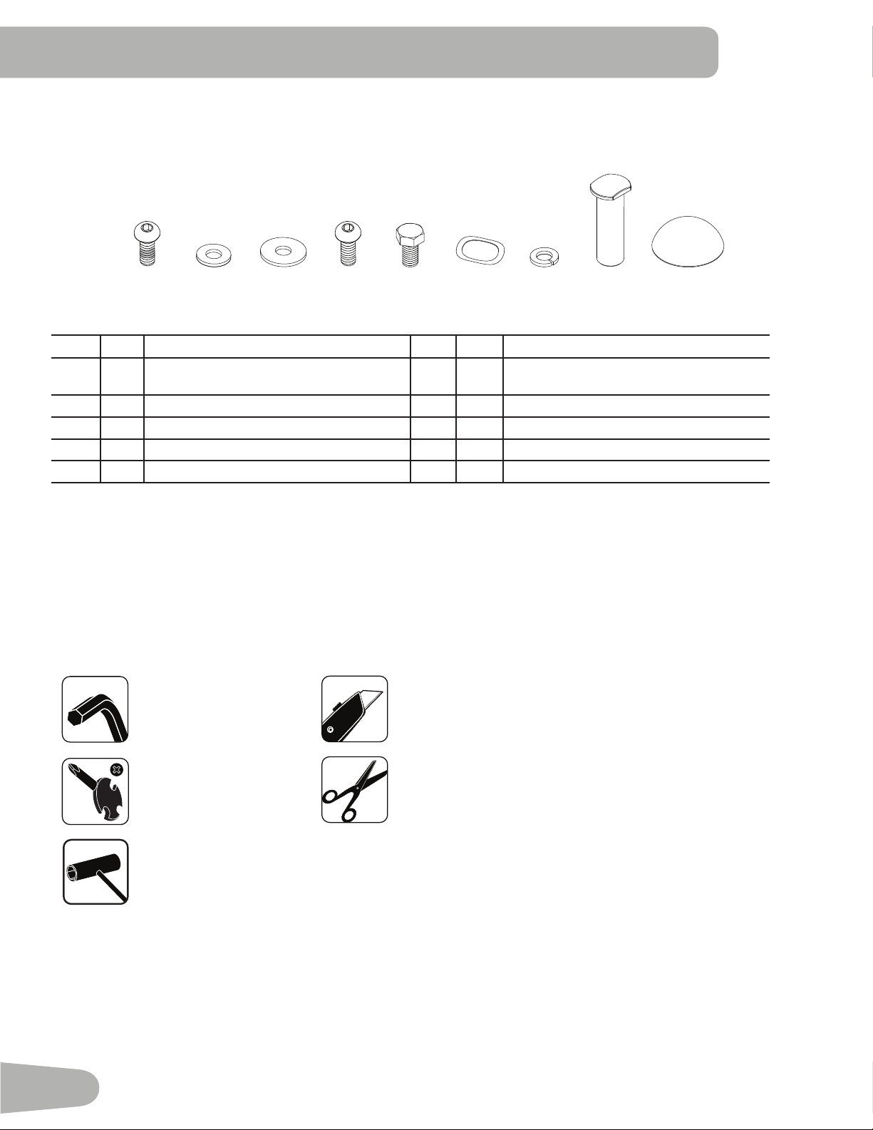
Item Qty
Description
Item Qty
Description
A 6 Button Head Hex Screw, M8x16 (with
Loctite
®
adhesive)
F 6 Wave Washer
B 4 Flat Washer, M8 G 12 Lock Washer, M8
C 8 Wide Washer, M8 H 2 Pivot Sleeve
D 4 Button Head Hex Screw, M8x16 I 2 Cap
E 2 Hex Head Screw, M8x20
Note: Select pieces of Hardware have been provided as spares on the Hardware Card. Be aware that there may
be remaining Hardware after the proper assembly of your machine.
HARDWARE / TOOLS
Tools
Included Not Included
6 mm
(recommended)
#2
13 mm
15 mm
19 mm
A B C D E F
G H
I

9
ASSEMBLY
1. Attach Front Stabilizer to Frame
Note: Hardware is pre-installed and not on the Hardware Card. *
13
11
6mm
*
*
X4
*
10
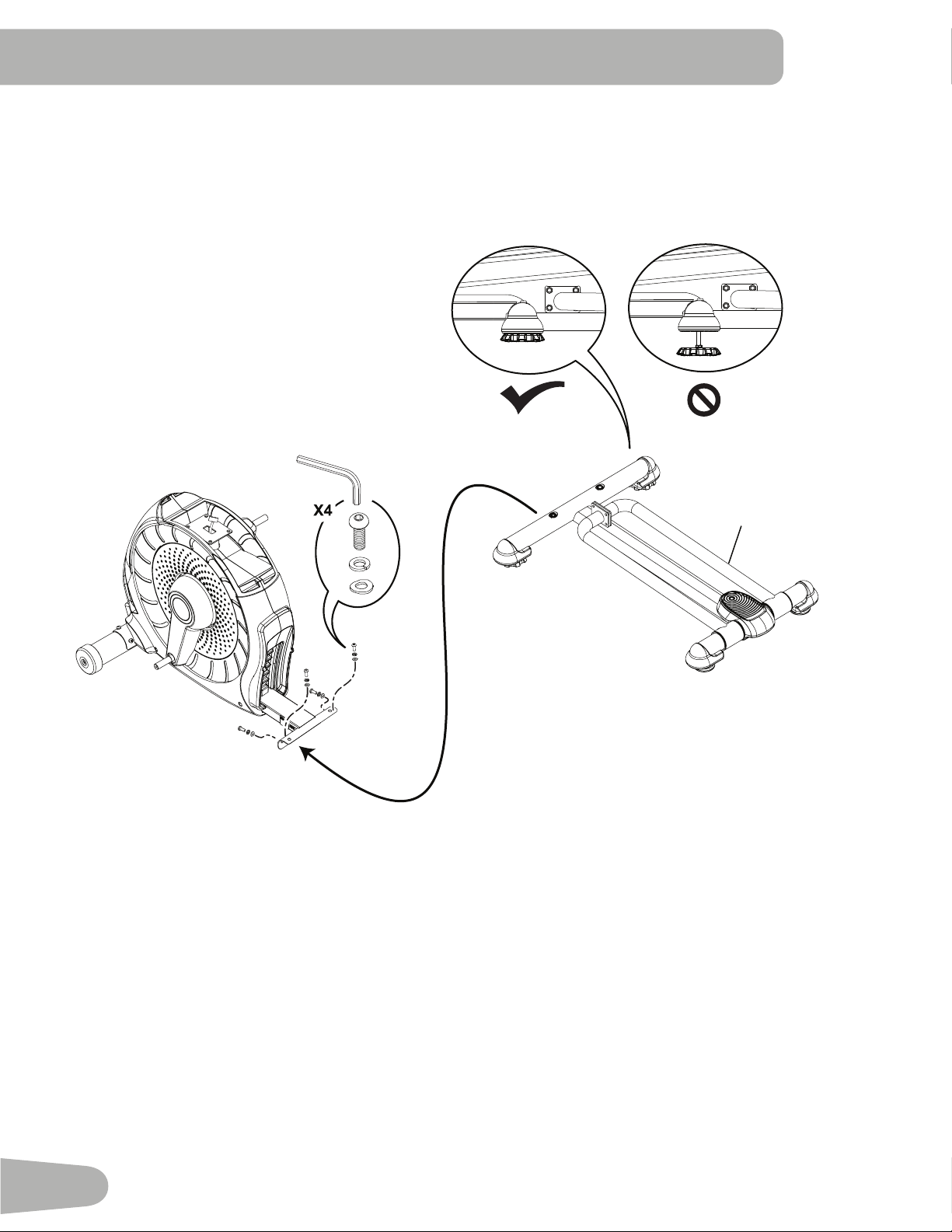
2. Attach Rail Assembly to Frame Assembly
Note: Be sure Levelers are fully raised on Rail Assembly. Hardware is pre-installed and not on the Hardware Card. *
9
6mm
*
*
*
11
3. Attach the Manual Lift Assembly using the Arm Pivot Rod
Note: Hardware is pre-installed and not on the Hardware Card. *
NOTICE : With the Arm Pivot Rod under the plate junction, push the Manual Lift Assembly toward the Frame Assem-
bly and fully tighten hardware. Remove the Arm Pivot Rod after tightening.
Keep fingers away from any pinch opportunities when placing or removing the Arm Pivot Rod.
*
*
21
3
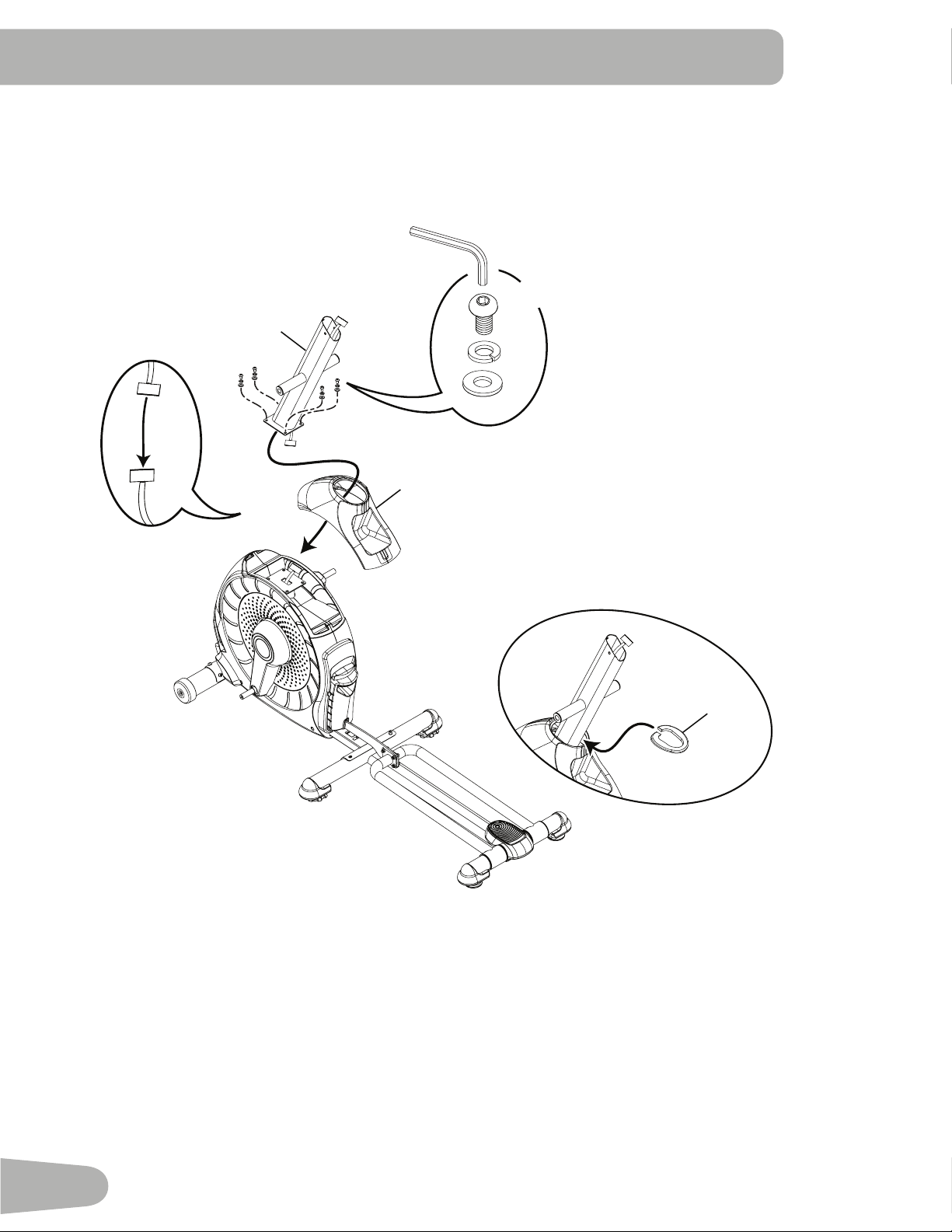
12
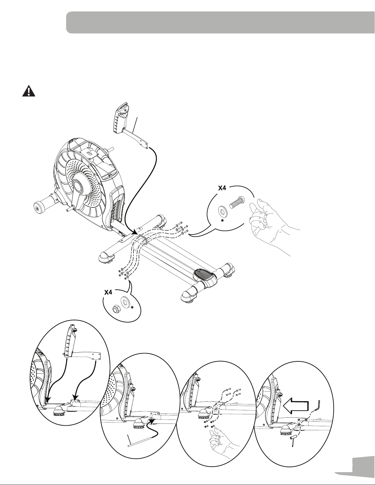
4. Connect the Cable and Attach the Console Mast to Frame Assembly
NOTICE : Do not crimp Console Cable.
16
1
12
B
D
G
6mm
X4
13
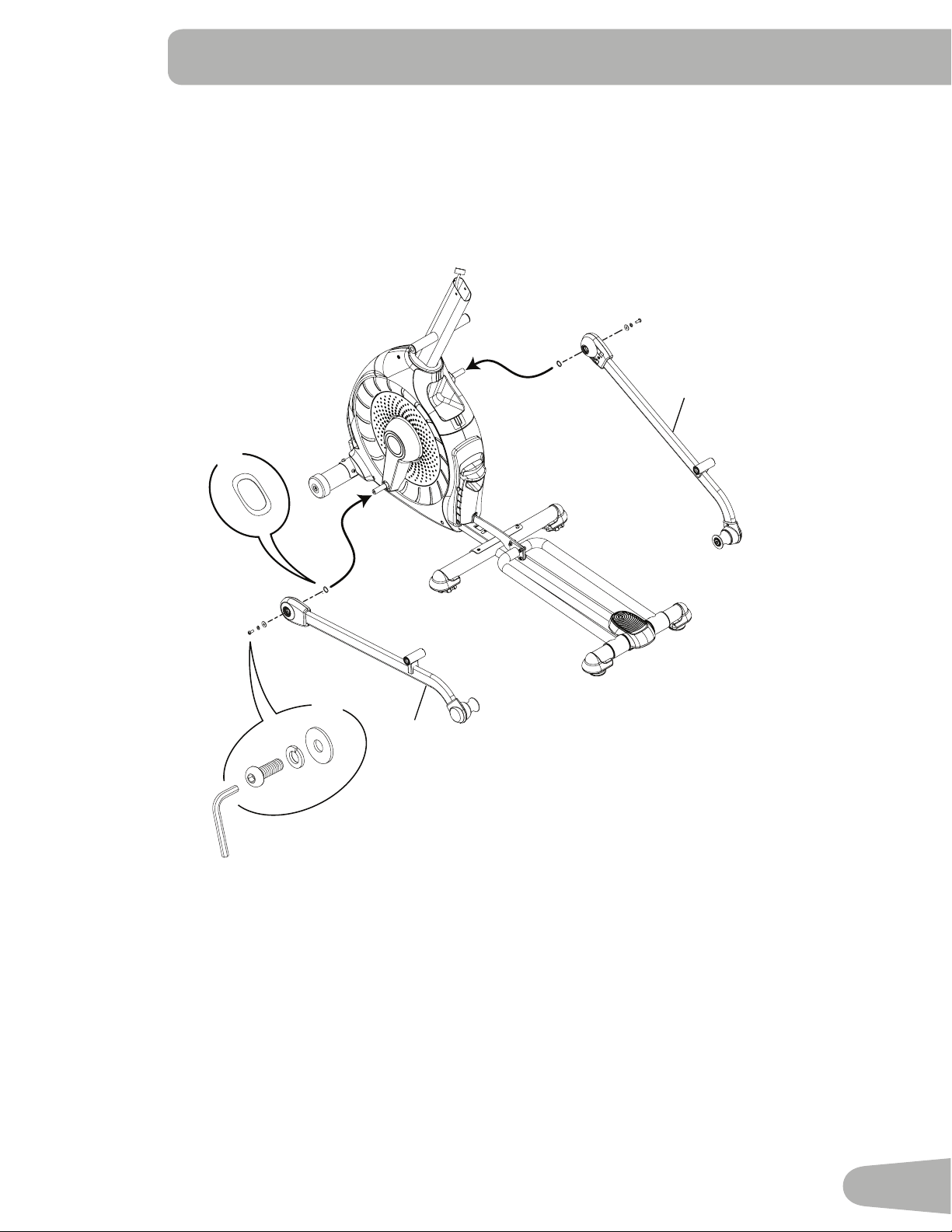
5. Attach Legs to Frame Assembly
10
14
F
X2
A
C
G
X2
6mm
14
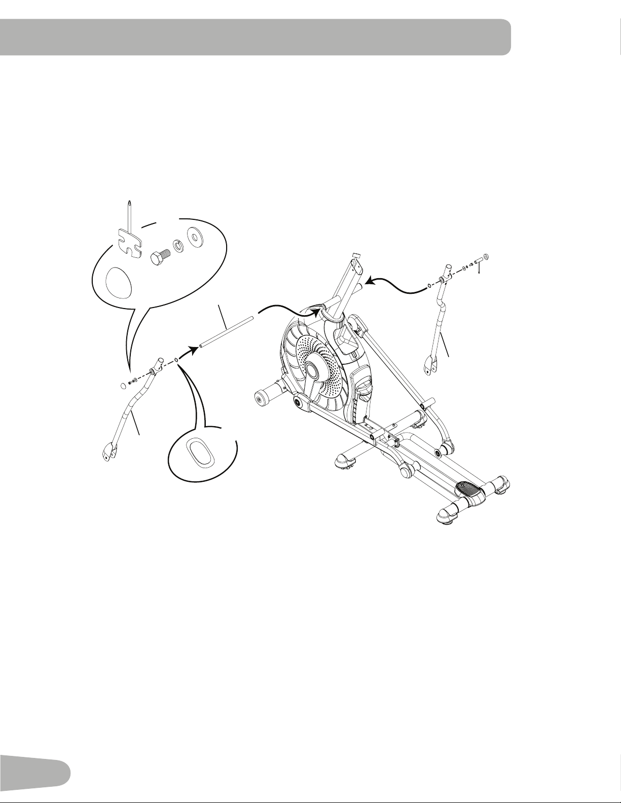
6. Attach Arm Pivot Rod and Lower Handlebar Arms to Frame Assembly
17
3
7
C
G
E
F
I
X2
X2
13 mm
15
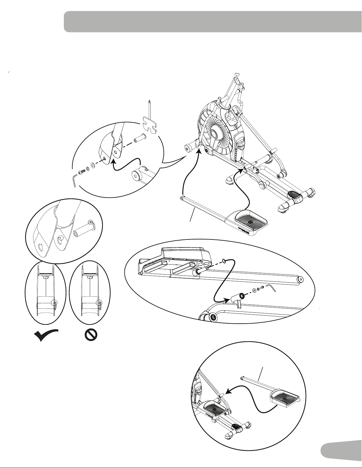
7. Attach Left Pedal to Frame Assembly
NOTICE: Attach the Pedal to the Leg first. Make sure the Pivot Sleeve (H) engages the Handlebar knuckle cover.
Repeat step on opposite side with the Right Pedal (Item 15).
15
A
C
G
F
8
C
H
G
A
6mm
H
16
8. Attach the Upper Handlebar Arms to Frame Assembly
Note: Hardware is pre-installed and not on the Hardware Card. *
Make sure the Upper Handlebar Arms are secure before you exercise.
6mm
18
6
X8
*
*
*

17
9. Route Cables and Attach the Static Handlebar to Frame Assembly
Note: Hardware is pre-installed and not on the Hardware Card. *
NOTICE : Do not crimp the Console Cables.
2
X3
6mm
*
*
*
18
10. Attach Water Bottle Holder to Frame Assembly
Note: Hardware is pre-installed and not on the Hardware Card. *
4
#2
*
X3
19
11. Remove Hardware from Console
NOTICE : Do not crimp the cable.
Note: Hardware is pre-installed and not on the Hardware Card. *
5
*
X4
#2
12. Connect Cables and Attach Console to Frame Assembly
NOTICE : Align the clips on the cable connectors and make sure the connectors lock. Do not crimp cables.
#2
*
X4
20
13. Connect AC Power Adapter to Frame Assembly
14. Final Inspection
Inspect your machine to ensure that all hardware is tight and components are properly assembled.
Note: If necessary, apply silicone lubricant to a cloth and wipe the rails to eliminate roller noise.
Silicone lubricant is not intended for human consumption. Keep out of reach of children.
Store in a safe place.
Be sure to record the serial number in the eld provided at the front of this manual.
Do not use until the machine has been fully assembled and inspected for correct performance in accor-
dance with the Owner’s Manual.
19
22
21
Moving the Machine
The machine may be moved by one or more persons depending on their physical abilities and capacities.
Make sure that you and others are all physically t and able to move the machine safely.
1. Remove the power cord.
2. Use the Transport Handle to carefully lift the machine onto the transport rollers.
3. Push the machine into position.
4. Carefully lower the machine into position.
NOTICE: Be careful when you move the elliptical. All abrupt
motions can affect the computer operation.
BEFORE YOU START
Leveling the Machine
The machine needs to be leveled if your workout area is uneven or if the Rail Assembly is slightly off the oor. To adjust:
1. Place the machine in your workout area.
2. Safely stand on the back of the Rail Assembly for approximately 20 seconds.
3. Step off the machine.
4. Loosen the locking wing nuts and adjust the
levelers until they all contact the oor.
Do not adjust the levelers to such a height
that they detach or unscrew from the
machine. Injury to you or damage to the
machine can occur.
5. Adjust until the machine is level. Tighten the
locking wing nuts.
Make sure the machine is level and stable before
you exercise.
22
FEATURES
A Speakers L Foot Pedal
B Console M Transport Handle
C Media Tray N Rail
D Fan O Incline Arm
E Handlebar Arm P Leveler
F Contact Heart Rate (CHR) Sensors Q Stabilizer
G Handlebar, Static R Transport Roller
H Water Bottle Holder S Power Connector
I Storage Bin T Fully Shrouded Flywheel
J Incline Release Button U USB Port
K Incline Adjustment Handle V MP3 Input
Use the values calculated or measured by the machine’s computer for reference purposes only.
The heart rate displayed is an approximation and should be used for reference only. Over
exercising may result in serious injury or death. If you feel faint stop exercising immediately.
U
V
H
F
G
E
A
D
C
B
P
S
I
J
T
N
R
Q
L
M
O
K
23
Console Features
The Console provides important information about your workout and lets you control the resistance levels while you
exercise. The Console features the Schwinn Dual Track
™
display with touch control buttons to navigate you through the
exercise programs.
Keypad Functions
Resistance Increase () button- Increases the workout resistance level
Resistance Decrease () button- Decreases the workout resistance level
QUICK START button- Begins a Quick Start workout
PROGRAMS button- Selects a category and workout program
PAUSE / END button- Pauses an active workout, ends a paused workout, or goes back to the previous screen
GOAL TRACK button-Displays the Workout Totals and Achievements for the selected User Prole
Increase () button- Increases a value (age, time, distance, or calories) or moves through options
Left () button- Displays different workout values during a workout, and moves through options
OK button- Starts a Program workout, conrms information, or resumes a paused workout.
Right () button- Displays different workout values during a workout, and moves through options
Decrease () button- Decreases a value (age, time, distance, or calories) or moves through options
FAN button- Controls 3-speed fan
Upper Display
Hr
Lower Display
Resistance Level Quick Buttons
Resistance Level Quick Buttons
Achievement Indicator Lights
Fan

24
Resistance Level Quick Buttons- Shifts the resistance levels to the setting quickly during a workout
Achievement Indicator Lights- when a workout result is reviewed, the achievement indicator light will activate.
Schwinn Dual Track™ Display
Upper Display Data
Program Display
The Program Display shows information to the User and the grid display area shows the course prole for the program.
Each column in the prole shows one interval (workout segment). The higher the column, the higher the resistance level.
The ashing column shows your current interval.
Intensity Display
The Intensity Display shows the level of work at that moment based on the current resistance level.
Heart Rate Zone Display
The Heart Rate Zone shows which zone the current heart rate value falls into for the current User. These Heart Rate
Zones can be used as a workout guide for a certain target zone (anaerobic, aerobic, or fat burn).
Consult a physician before you start an exercise program. Stop exercising if you feel pain or tightness in
your chest, become short of breath, or feel faint. Contact your doctor before you use the machine again.
The heart rate displayed is an approximation and should be used for reference only.
Note: If no heart rate is detected, the display will be blank.
Goal Display
The Goal Display shows the currently selected type of goal (Distance, Time or Calories), the current value to achieve the
goal, and the percent completed toward the goal.
User Display
The User Display shows which User Prole is currently selected.
Achievement Display
The Achievement Display activates when a workout goal is reached or a workout milestone is surpassed from past
workouts. The Console display will congratulate and inform the User of their achievement, along with a celebratory sound.
10%
40%
70%
1
2
3
4
5
6
7
8
9
10
User Display
Achievement Display

25
Lower Display Data
The Lower Display shows the Workout Values and can be customized for each User (Consult the “Edit User Prole”
section of this manual). Use the Right() button to move through all the workout statistics.
Speed
The Speed display eld shows the machine speed in miles per hour (mph) or kilometers per hour (km/h).
Time
The TIME display eld shows the total time count of the workout, the average Time for the User Prole, or the total opera-
tional time of the machine.
Note: If a Quick Start workout is performed for more than 99 minutes and 59 seconds (99:59), the units for Time will
shift to hours and minutes ( 1 hour, 40 minutes ).
Distance
The Distance display shows the distance count (miles or km) in the workout.
Note: To change the measurement units to English Imperial or metric, refer to the “Console Setup Mode” section in this
manual.
Level
The LEVEL display shows the current resistance level in the workout.
RPM
The RPM display eld shows the pedal revolutions per minute (RPM).
Heart Rate (Pulse)
The Heart Rate display shows the beats per minute (BPM) from the heart rate monitor. When a heart rate signal is re-
ceived by the Console, the icon will ash.
Consult a physician before you start an exercise program. Stop exercising if you feel pain or tightness in
your chest, become short of breath, or feel faint. Contact your doctor before you use the machine again.
The heart rate displayed is an approximation and should be used for reference only.
Calories
The Calories display eld shows the estimated calories that you have burned during the exercise.
Hr

26
Export Workout Results to USB Flash Drive
This tness machine is equipped with a USB Port and can export your Workout Results to a USB Flash Drive. With the
Workouts exported from the tness machine, connect the USB Flash Drive to a computer and upload the le to your Sch-
winn Connect™ account.
Note: USB Flash Drives must be formatted in FAT32 for proper functionality.
1. From the Power-Up screen, push the User button to select the desired User Prole.
2. Insert the USB Flash Drive into the USB Port on the Console.
3. The Console will display “SAVING TO USB”, and then “DO NOT REMOVE”. The current User Prole will begin to
ash, showing the Workout Results are being exported to the USB Flash Drive. Do not remove the USB Flash Drive
until the User Prole does not ash and the Console displays “REMOVE USB”.
Note: If the Workout Results on the USB Flash Drive are current, the Console will not export the le again. As more
workouts are completed, the Console will take longer to export all of the Workout Results. For longer exports, the
Console will display an export status count ( exported workouts / total number of workouts ).
4. When the export is complete the User Prole will stop ashing, the Console will display “USB COMPLETE”, followed
by the “REMOVE USB” prompt. It is now safe to remove the USB Flash Drive.
5. The Console will display the Power-Up Mode screen.
If a Workout is completed with a USB Flash Drive already inserted, the Console will not export the new Workout Results
until the Console exits the Results mode and displays the Power-Up Mode screen.
Track Your Results at www.schwinnconnect.com
Take advantage of the Schwinn Connect™ website to see your progress over time and share your data with MyFitness-
Pal
®
. Review your workouts and results away from the machine when convenient for you. The Schwinn Connect™ web-
site allows for a workout value to be selected and have it graphed for weekly, monthly, or yearly comparison review.
If using a USB Flash Drive to import workout results to the Schwinn Connect™ website:
1. Insert the USB Flash Drive with your workout data into a device connected to the internet.
2. Sign in to the Schwinn Connect™ website at www.schwinnconnect.com.
3. Click the Upload button on the web site.
4. In the Upload File window, locate your USB Flash Drive. Select the workout data le from it, and click the upload
button. Your workout data will upload into your account.
Note: The name of the data le will either be the selected User (“ USER1.DAT “) or the name of the customized User
(example- “ JOHN.DAT “), followed by the .DAT le format.
5. To sync your workout data with MyFitnessPal
®
, select the Menu option in the upper left corner of the web page and
select the “Sync to MyFitnessPal
®
“ option.
Note: The Schwinn Connect™ software will automatically sync your workouts with MyFitnessPal
®
after the initial
syncing.
Contact Heart Rate Sensors
Contact Heart Rate (CHR) sensors send your heart rate signals to the Console. The CHR sensors are the stainless steel
parts of the Handlebars. To use, put your hands comfortably around the sensors. Be sure that your hands touch both the
top and the bottom of the sensors. Hold rm, but not too tight or loose. Both hands must make contact with the sensors for
the Console to detect a pulse. After the Console detects four stable pulse signals, your initial pulse rate will be shown.
27
Once the Console has your initial heart rate, do not move or shift your hands for 10 to 15 seconds. The Console will now
validate the heart rate. Many factors inuence the ability of the sensors to detect your heart rate signal:
• Movement of the upper body muscles (including arms) produces an electrical signal (muscle artifact) that can interfere
with pulse detection. Slight hand movement while in contact with the sensors can also produce interference.
• Calluses and hand lotion may act as an insulating layer to reduce the signal strength.
• Some Electrocardiogram (EKG) signals generated by individuals are not strong enough to be detected by the sensors.
• The proximity of other electronic machines can generate interference.
If your heart rate signal ever seems erratic after validation, wipe off your hands and the sensors and try again.
Heart Rate Calculations
Your maximum heart rate usually decreases from 220 Beats Per Minute (BPM) in childhood to approximately 160 BPM by
age 60. This fall in heart rate is usually linear, decreasing by approximately one BPM for each year. There is no indication
that training inuences the decrease in maximum heart rate. Individuals of the same age could have different maximum
heart rates. It is more accurate to nd this value by completing a stress test than by using an age related formula.
Your at-rest heart rate is inuenced by endurance training. The typical adult has an at rest heart rate of approximately 72
BPM, whereas highly trained runners may have readings of 40 BPM or lower.
The Heart Rate table is an estimate of what Heart Rate Zone (HRZ) is effective to burn fat and improve your cardiovas-
cular system. Physical conditions vary, therefore your individual HRZ could be several beats higher or lower than what is
shown.
The most efcient procedure to burn fat during exercise is to start at a slow pace and gradually increase your intensity un-
til your heart rate reaches between 60 – 85% of your maximum heart rate. Continue at that pace, keeping your heart rate
in that target zone for over 20 minutes. The longer you maintain your target heart rate, the more fat your body will burn.
The graph is a brief guideline, describing the generally suggested target heart rates based on age. As noted above, your
optimal target rate may be higher or lower. Consult your physician for your individual target heart rate zone.
Note: As with all exercises and tness regimens, always use your best judgment when you increase your exercise
time or intensity.
20-24
FAT-BURNINGTARGETHEARTRATE
HeartRateBPM
(beatsperminute)
Age
25-29
0
50
100
150
200
250
30-3435-3940-4445-4950-54 55-5960-6465-6970+
196
191
186
181
176
171
166
161
156
151
146
167
162
158
154
150
145
141
137
133
128
126
MaximumHeartRate
TargetHeartRateZone
(keepwithinthisrange
foroptimumfat-burning)
118
115
112
109
106
103
100
97
94
91
88
28
OPERATIONS
What to Wear
Wear rubber-soled athletic shoes. You will need the appropriate clothes for exercise that allow you to move freely.
How Often Should You Exercise
Consult a physician before you start an exercise program. Stop exercising if you feel pain or tightness in
your chest, become short of breath, or feel faint. Contact your doctor before you use the machine again.
Use the values calculated or measured by the machine’s computer for reference purposes only. The heart
rate displayed on the console is an approximation and should be used for reference only.
• 3 times a week for 30 minutes each day.
• Schedule workouts in advance and try to follow the schedule.
Mounting and Dismounting Your Machine
Care should be used when mounting or dismounting the machine.
Be aware that the Pedals and the Handlebars are connected and when either of these parts move the
other does as well. In order to avoid possible serious injury, only grasp the Static Handlebars to steady
yourself.
To mount your tness machine:
1. Move the Pedals until the one nearest you is in the lowest position.
2. Grasp the Static Handlebars under the Console.
3. Steadying yourself with the Static Handlebars, step up onto the lowest Pedal and place your other foot onto the
opposite Pedal.
To dismount your tness machine:
1. Move the Pedal you want to dismount from to the highest position, and bring the machine to a complete stop.
This machine is not equipped with a free-wheel. Pedal speed should be reduced in a controlled manner.
2. Grasp the Static Handlebars under the Console to steady yourself.
3. With your weight on the lowest foot, swing the upper foot off the machine and down onto the oor.
4. Step off of the machine and release your grip from the Static Handlebars.
Workout Incline Adjustment
The angle of the Rails can be increased for a more intense workout.
Do not adjust the workout angle when on the machine.
Fully lower the Incline Assembly after each workout.
1. Grasp the Incline Adjustment Handle and lift it to adjust the workout angle.
2. Release the handle when the Rails are near the desired angle. When released,
the Incline Assembly will catch and hold the workout angle.
3. Push down on the Pedals to be sure the Rails are secured by the Incline
Assembly.
Note: Do not step onto the machine until you know the Incline Assembly is
secure. Be sure that the workout space you are utilizing has adequate height
clearance, taking into consideration the height of the user and the maximum incline of the elliptical machine.
29
To release the Incline Assembly:
Do not adjust the workout angle when on the machine.
1. Grasp the Incline Adjustment Handle and push the Incline Release Button with
the palm of your hand. Be prepared to support the weight of the raised parts of the
machine.
When released, the Incline Assembly may fully disengage. Make sure that
you are able to support the weight of the raised parts of the machine safely.
Note: The Incline Handle may need to be slightly lifted to disengage the Incline Assembly.
2. Lower to the desired height.
In order to avoid possible serious injury when lowering the Rails, be careful to avoid ngers or hands being
caught or pinched.
4. Release the Incline Release Button.
5. Push down on the Pedals to be sure the Rails are secured by the Incline Assembly.
Note: Do not step onto the machine until you know the Incline Assembly is secure.
Power-Up / Idle Mode
The Console will enter Power-Up / Idle Mode if it is plugged into a power source, any button is pushed, or if it receives a
signal from the RPM sensor as a result of pedaling the machine.
Auto Shut-Off (Sleep Mode)
If the Console does not receive any input in approximately 5 minutes, it will automatically shut off. The LCD display is off
while in Sleep Mode.
Note: The Console does not have an On/Off switch.
Initial Setup
During the rst power-up, the Console should be setup with the date, time and your preferred measurement units.
1. Date: Push the Increase/Decrease buttons to adjust the currently active value (ashing). Push the Left/Right buttons
to change which segment is the currently active value (month / day / year).
2. Push OK to set.
3. Time: Push the Increase/Decrease buttons to adjust the currently active value (ashing). Push the Left/Right buttons
to change which segment is the currently active value (hour / minute / AM or PM).
4. Push OK to set.
5. Units of Measurement: Push the Increase/Decrease buttons to adjust between “MILES” (Imperial English) or “KM”
(metric).
6. Push OK to set. The Console goes back to the Power-Up / Idle Mode screen.
Note: To adjust these selections, consult the “Console Set-Up Mode” section.

30
Quick Start ( Manual ) Program
The Quick Start ( Manual ) program lets you start a workout without entering any information.
During a Manual Workout, each column represents a 2 minute time period. The active column will advance across the
screen every 2 minutes. If the workout lasts for more than 30 minutes, the active column is xed on the farthest column on
the right and pushes the previous columns off the display.
1. Stand on the machine.
2. Push the Increase/Decrease button to select the correct User prole. If you do not have a User prole set up, you can
select a User prole that has no customized data (default values only).
3. Push the QUICK START button to start the Manual program.
4. To change the resistance level, push the Resistance Increase/Decrease buttons. The current interval and future
intervals are set to the new level. The default Manual resistance level is 4. The time will count up from 00:00.
Note: If a Manual workout is performed for more than 99 minutes and 59 seconds (99:59), the units for Time will shift
to hours and minutes ( 1 hour, 40 minutes ).
5. When done with your workout, stop pedaling and push PAUSE/END to pause the workout. Push PAUSE/END again
to end the workout.
Note: The workout results are recorded to the current User Profile.
User Profiles
The Console lets you store and use 2 User profiles. The User profiles automatically record the workout results for each
workout, and allow the workout data to be reviewed.
The User profile stores the following data:
• Name—up to 10 characters
• Age
• Weight
• Height
• Gender
• Preferred Workout Values
Select a User Profile
Every workout is saved to a User Prole. Be sure to select the proper User Prole before starting a workout. The last User
that completed a workout will be the default user.
User Proles are assigned the default values until they are customized by editing. Be sure to edit the User Prole for more
accurate calorie and heart rate information.
From the Power-Up Mode screen, push the Increase() or Decrease() buttons to select one of the User Proles. The
Console will display the name of the User Prole and the User Prole Icon.
Edit User Profile
1. From the Power-Up Mode screen, push the Increase() or Decrease() buttons to select one of the User Proles.
2. Push the OK button to select the User Profile.
3. The Console display shows the EDIT prompt and the current User Profile name. Push OK to start the Edit User Prole
option.
To exit the Edit User Prole option, push the PAUSE/END button and the console will go back to the Power-Up Mode
screen.

31
4. The Console display shows the NAME prompt and the current User Profile name.
Note: The User name will be blank if this is the first edit. The name of a User Profile is limited to 10 characters.
The currently active segment will flash. Use the Increase/Decrease buttons to move through the alphabet and blank
space (found between A and Z). To set each segment, use the Left() or Right() buttons to shift between segments.
Push the OK button to accept the displayed User name.
5. To edit the other User data (EDIT AGE, EDIT WEIGHT, EDIT HEIGHT, EDIT GENDER), use the Increase/Decrease
buttons to adjust, and push OK to set each entry.
6. The Console display shows the SCAN prompt. This option controls how the workout values are displayed in the Lower
Display during a workout. The “OFF” setting allows the user to push the RIGHT or LEFT buttons to view the other
workout value channels when desired. The “ON” setting allows the Console to automatically display the workout value
channels every 6 seconds.
The default is “OFF”.
Push the OK button to set how the workout values are displayed.
7. The Console display shows the EDIT LOWER DISPLAY prompt. This option allows you to customize which Workout
Values are displayed during a workout.
The Lower Display will show all of the workout values, with the active Workout Value ashing. The Upper Display
shows the active value setting: “ON” or “OFF”. Push the Increase() or Decrease() buttons to hide the active
workout value, and push the Left() or Right() buttons to shift the active workout value.
Note: To show a hidden workout value, repeat procedure and change Upper Display value to “ON” for that value.
When done with customizing the Lower Display, push the OK button to set it.
Hr
8. The Console will go to the Power-Up Mode screen with the user selected.
Reset a User Profile
1. From the Power-Up Mode screen, push the Increase() or Decrease() buttons to select one of the User Proles.
2. Push the OK button to select the User Profile.
3. The Console display shows the current User Profile name and the EDIT prompt. Push the Increase() or Decrease()
buttons to change the prompt.
Note: To exit the Edit User Prole option, push the PAUSE/END button and the console will go back to the Power-Up
Mode screen.
4. The Console display shows the RESET prompt and the current User Profile name. Push OK to start the Reset User
Prole option.
5. The Console will now confirm the request to reset the User profile (the default selection is ‘NO’). Push the Increase()
or Decrease() buttons to adjust the selection.
6. Push OK to make your selection.
7. The Console will go to the Power-Up Mode screen.
32
Changing Resistance Levels
Push the Resistance Level Increase() or Decrease() buttons to change the resistance level at any time in a workout
program. To rapidly change the resistance level, push the desired Resistance Level Quick Button. The Console will adjust
to the selected resistance level of the quick button.
Prole Programs
These programs automate different resistance and workout levels. The Prole Programs are organized into Categories
(Fun Rides, Mountains, and Challenges).
Note: Once a User views all the Categories, they will be expanded to display the Programs within each of the
Categories.
FUN RIDES
Rolling Hills Ride in the Park
Easy Tour
MOUNTAINS
Pike’s Peak Mount Hood
Pyramids
CHALLENGES
Uphill Finish Cross-Training
Interval

33
Workout Prole and Goal Program
The Console lets you select the Prole Program and type of Goal for your workout (Distance, Time or Calories), and set
the Goal value.
1. Stand on the machine.
2. Push the Increase() or Decrease() buttons to select the correct User prole.
3. Push the Programs button.
4. Push the Left() or Right() buttons to select a Category of Workout.
5. Push the Increase() or Decrease() buttons to select a Profile Workout, and push OK.
6. Use the Increase() or Decrease() buttons to select a type of Goal (Distance, Time or Calories), and push OK.
7. Use the Increase() or Decrease() buttons to adjust the workout value.
8. Push OK to begin the goal-oriented workout. The GOAL value will count down as the value for percent completed
increases.
Note: During a Calories Goal, each column is for a 2 minute time period. The active column will advance across
the screen every 2 minutes. If the workout lasts for more than 30 minutes, the active column will x to the last right
column and push the previous columns off the display.
Fitness Test Program
The Fitness Test measures the improvements of your physical tness level. The test compares your power output (in
Watts) to your heart rate. As your tness level improves, your power output will increase at a given heart rate.
Note: The Console must be able to read the heart rate information from the Contact Heart Rate (CHR) sensors to work
correctly.
You can start the Fitness Test from the FEEDBACK category. The Fitness Test program rst prompts you to select your
tness level—Beginner ( “BEG” ) or Advanced ( “ADV” ). The Console will use the Age and Weight values for the selected
User Prole to calculate the Fitness Score.
Start to workout and hold the Heart Rate Sensors. When the test starts, the intensity of the workout slowly increases. This
means you will work harder, and as a result, your heart rate increases. The intensity continues to increase automatically
until your heart rate reaches the “Test Zone”. This zone is individually computed to be near 75 percent of the maximum
heart rate of your User Prole. When you reach the Test Zone, the machine holds the intensity steady for 3 minutes.
This lets you reach a stable condition (where your heart rate becomes steady). At the end of the 3 minutes, the Console
measures your heart rate and the power output. These numbers, along with information about your age and weight, are
computed to produce a “Fitness Score”.
Note: Fitness Test scores should only be compared to your previous scores and not to other User Profiles.
Compare your Fitness Scores to see your improvement.

34
Heart Rate Control (HRC) Workout Programs
The Heart Rate Control (HRC) programs let you set a heart rate goal for your workout. The program monitors your heart
rate in beats per minute (BPM) from the Contact Heart Rate (CHR) sensors on the machine, and adjusts the workout to
keep your heart rate in the selected zone.
Note: The console must be able to read the heart rate information from the CHR sensors for the HRC program to work
correctly.
The Target Heart Rate programs use your age and other User information to set the Heart Rate Zone values for your
workout. The console display then gives prompts for you to set up your workout:
1. Select the Heart Rate Control workout level: BEGINNER ( “BEG” ) or ADVANCED ( “ADV” ) and push OK.
2. Push the Increase() and Decrease() buttons to select the percentage of maximum heart rate: 50–60%, 60–70%,
70–80%, 80–90%.
Consult a physician before you start an exercise program. Stop exercising if you feel pain or tightness in
your chest, become short of breath, or feel faint. Contact your doctor before you use the machine again.
Use the values calculated or measured by the machine’s computer for reference purposes only. The heart
rate displayed on the console is an approximation and should be used for reference only.
3. Push the Increase() or Decrease() buttons to select the Goal type, and push OK.
4. Push the Increase() or Decrease() buttons to set the goal value for the workout.
Note: Be sure to allow time for your heart rate to reach the desired heart rate zone when setting the goal.
5. Push OK to start the workout.
Changing a Workout Program During a Workout
The Console allows a different Workout Program to be started from an active workout.
1. From an active workout, push PROGRAMS.
2. Push the Increase() or Decrease() buttons to select the desired workout program, and push OK.
3. Push the Increase() or Decrease() buttons to select the Goal type, and push OK.
4. Push the Increase() or Decrease() buttons to set the value for the workout.
5. Push OK to stop the active workout and start the new workout.
The previous workout values are saved to the User Prole.
Pausing or Stopping
The Console will go into Pause Mode if the user stops pedaling and pushes PAUSE/END during a workout, or there is no
RPM signal for 5 seconds (user not pedaling). The Console will cycle through a series of messages that change every 4
seconds:
- WORKOUT PAUSED
- PEDAL TO CONTINUE (if a bike) / STRIDE TO CONTINUE (if an elliptical)
- PUSH END TO STOP
During a paused workout, you can use the Increase/Decrease buttons to move through the result channels manually.
1. Stop pedaling and push the PAUSE/END button to pause your workout.
2. To continue your workout, push OK or start pedaling.
To stop the workout, push the PAUSE/END button. The Console will go into Results / Cool Down mode.

35
Results / Cool Down Mode
After a workout the GOAL display shows 03:00 and then starts to count down. During this Cool Down period, the Console
shows the Workout Results. All workouts except Quick Start have a 3-minute Cool Down period.
After a workout the GOAL display shows 03:00 and then starts to count down. During this Cool Down period, the Console
shows the Workout Results. All workouts except Quick Start have a 3-minute Cool Down period.
The LCD display shows the Current Workout values in three channels:
a.) TIME (total), DISTANCE (total), and CALORIES (total)
b.) SPEED (average), RPM (average), and HEART RATE (average)
c.) TIME (average), LEVEL (average), and CALORIES (average).
Push the Left() or Right() buttons to move through the result channels manually.
During the Cool Down period, the Resistance Level will adjust to a third of the average Level of the workout. The Cool
Down resistance level can be adjusted with the Resistance Increase and Decrease buttons, but the Console will not dis-
play the value.
You can push PAUSE/END to stop the Results / Cool Down period and go back to Power-Up Mode. If there is no RPM or
HR signal, the Console automatically goes into Sleep Mode.
GOAL TRACK Statistics (and Achievements)
The statistics from every workout are recorded to a User Prole.
The Schwinn Dual Track
™
Console shows the Goal Track workout Statistics on the Lower Display in three channels:
a.) TIME (total), DISTANCE (total), and CALORIES (total)
b.) SPEED (average), RPM (average), and HEART RATE (average)
c.) TIME (average), DISTANCE (average) / or LEVEL (average) *, and CALORIES (average)
* If the Goal Track Statistic is a single workout, LEVEL (average) is displayed. If the Goal Track Statistic is a
combination of multiple workouts, DISTANCE (average) is displayed instead of LEVEL (average).
To view the GOAL TRACK statistics of a User Prole:
1. From the Power-Up screen, push the Increase() and Decrease() buttons to select a User Profile.
2. Push the GOAL TRACK button. The Console will display the LAST WORKOUT values and activate the corresponding
Achievement light.
Note: Goal Track statistics can be viewed even during a workout. Push GOAL TRACK and the LAST WORKOUT
values will be displayed. The workout values for the current workout will be hidden except for the GOAL display. Push
GOAL TRACK again to return to the Power-Up screen.
3. Push the Increase() button to move to the next GOAL TRACK statistic, “LAST 7 DAYS”. The Console will display the
calories burnt on the display (50 calories per segment) for the previous seven days, along with the workout value totals.
Use the Left() or Right() buttons to move through all the workout statistic channels.
4. Push the Increase() button to move to “BMI”, or Body Mass Index. The Console will display the BMI value based on
the User settings. Be sure the height value is correct for your User Prole, and the weight value is current.

36
The BMI Measurement is a useful tool that shows the relationship between weight and height that is associated with body
fat and health risk. The table below gives a general rating for the BMI score:
Underweight Below 18.5
Normal 18.5 – 24.9
Overweight 25.0 – 29.9
Obesity 30.0 and above
Note: The rating may overestimate body fat in athletes and others who have a muscular build. It may also underesti-
mate body fat in older persons and others who have lost muscle mass.
Contact your doctor for more information about Body Mass Index (BMI) and the weight that is appropriate
for you. Use the values calculated or measured by the machine’s computer for reference purposes only.
5. Push the Increase() button to move to the “SAVE TO USB - OK?” prompt. Push OK, and the “ARE YOU SURE?
-NO” prompt will display. Push the Increase() button to change it to yes and push OK. The Console will display the
“INSERT USB” prompt. Insert a USB Flash Drive into the USB Port. The Console will record the Statistics to the USB
Flash Drive.
The Console will display “SAVING”, and then “REMOVE USB” when it is safe to remove the USB Flash Drive.
Note: Push the PAUSE/END button to force an exit from the “SAVING” prompt.
6. Push the Increase() button to move to the “CLEAR WORKOUT DATA -OK?”. Push OK, and the “ARE YOU SURE?
- NO” prompt will display. Push the Increase() button to change to the “ARE YOU SURE? - YES” display, and push
OK. The user workouts have been reset.
7. Push GOAL TRACK to return to the Power-Up screen.

37
CONSOLE SETUP MODE
The Console Setup Mode lets you input the date and time, set the units of measurement to either English or Metric,
change the machine type, control the sound settings ( on/ off), or see maintenance statistics (Error Log and Run Hours –
for service technician use only).
1. Hold down the PAUSE/END button and Right button together for 3 seconds while in the Power-Up Mode to go into
the Console Setup Mode.
Note: Push PAUSE/END to exit the Console Setup Mode and return to the Power-Up Mode screen.
2. The Console display shows the Date prompt with the current setting. To change, push the Increase/Decrease buttons
to adjust the currently active value (ashing). Push the Left/Right buttons to change which segment is the currently
active value (month / day / year).
3. Push OK to set.
4. The Console display shows the Time prompt with the current setting. Push the Increase/Decrease buttons to adjust
the currently active value (ashing). Push the Left/Right buttons to change which segment is the currently active value
(hour / minute / AM or PM).
5. Push OK to set.
6. The Console display shows the Units prompt with the current setting. To change, push OK to start the Units option.
Push the Increase/Decrease buttons to change between “MILES” (Imperial English units) and “KM” (metric units).
Note: If the units change when there is data in User Statistics, the statistics convert to the new units.
7. Push OK to set.
8. The Console display shows the Machine Type prompt with the current setting. Push the Increase/Decrease buttons to
change between “BIKE” and Elliptical (“ELIP”).
9. Push OK to set.
10. The Console display shows the Sound Settings prompt with the current setting. Push the Increase/Decrease buttons
to change between “ON” and “OFF”.
11. Push OK to set.
12. The Console display shows the TOTAL RUN HOURS for the machine.
13. For the next prompt, push the OK button.
14. The Console display shows the Software Version prompt.
15. For the next prompt, push the OK button.
16 . The Console will display the Power-Up Mode screen.

38
MAINTENANCE
Read all maintenance instructions fully before you start any repair work. In some conditions, an assistant is required to do
the necessary tasks.
Equipment must be regularly examined for damage and repairs. The owner is responsible to make sure that
regular maintenance is done. Worn or damaged components must be repaired or replaced immediately.
Only manufacturer supplied components can be used to maintain and repair the equipment.
If at any time the Warning labels become loose, unreadable or dislodged, contact Nautilus Customer Ser-
vice for replacement labels.
To reduce the risk of electrical shock or unsupervised usage of the equipment, always unplug the
power cord from the wall outlet and the machine and wait 5 minutes before cleaning, maintaining or repairing
the machine. Place the power cord in a secure location.
Daily: Before each use, examine the exercise machine for loose, broken,
damaged, or worn parts. Do not use if found in this condition. Repair
or replace all parts at the rst sign of wear or damage. After each
workout, use a damp cloth to wipe your machine and Console free of
sweat.
Note: Avoid excessive moisture on the Console.
Weekly: Check for smooth roller operation. Wipe the machine to remove dust,
dirt, or grime. Clean the rails and surface of the rollers with a damp
cloth.
Apply silicone lubricant to a dry cloth and wipe the rails to eliminate
roller noise.
Silicone lubricant is not intended for human consumption.
Keep out of reach of children. Store in a safe place.
Note: Do not use petroleum based products.
Monthly
or after 20
hours:
Make sure all bolts and screws are tight. Tighten as necessary.
NOTICE: Do not clean with a petroleum based solvent or an automotive cleaner. Be sure to keep the Console free
of moisture.
39
Maintenance Parts
W
X
Z
AA
Y
A
G
C
B
D
E
F
H
I
M
N
O
P
K
L
S
U
V
T
BB
EE
J
DD
GG
FF
HH
II
R
Q
M
CC
CC
A Console M Roller Y Fly Wheel
B Heart Rate Cable, Upper N Leg, Right Z Speed Sensor Magnet
C Handlebar, Static O Shroud Cap AA Speed Sensor
D Console Cable, Upper P Shroud, Upper BB Pedal Arm, Left
E Arm Pivot Rod Q Console Cable, Lower CC Transport Wheel
F Console Mast R Incline Assembly DD Front Stabilizer
G Water Bottle Holder S Frame Assembly EE Leg, Left
H Handlebar Arm, Lower Right T Rail Assembly FF AC Power Adapter
I Handlebar Arm, Upper Right U Shroud, Left GG MP3 Cable
J Pedal Arm, Right V Crank Assembly, Left HH Handlebar Arm, Lower Left
K Crank Assembly, Right W Servo Motor II Handlebar Arm, Upper Left
L Shroud, Right X Brake Assembly JJ Silicone Lubricant, Bottle

40
Condition/Problem Things to Check Solution
No display/partial display/
unit will not turn on
Check electrical (wall)
outlet
Make sure unit is plugged into a functioning wall outlet.
Check connection at front
of unit
Connection should be secure and undamaged. Replace
adapter or connection at unit if either are damaged.
Check data cable integrity All wires in cable should be intact. If any are visibly crimped or
cut, replace cable.
Check data cable
connections/orientation
Be sure cable is connected securely and oriented properly.
Small latch on connector should line up and snap into place.
Check console display for
damage
Check for visual sign that console display is cracked or other-
wise damaged. Replace Console if damaged.
Console Display If Console only has partial display and all connections are ne,
replace the Console.
If the above steps do not resolve the problem, contact Cus-
tomer Care for further assistance.
Unit operates but Contact
HR not displayed
HR cable connection at
Console
Be sure cable is connected securely to Console.
HR cable box connection Be sure cables from handlebars and cable to Console are
secure and undamaged.
Sensor grip Be sure hands are centered on HR sensors. Hands must be
kept still with relatively equal pressure applied to each side.
Dry or calloused hands Sensors may have difculty with dried out or calloused hands.
A conductive electrode cream (heart rate cream) can help
make better conduct. These are available on the web or at
medical or some larger tness stores.
Static Handlebar If tests reveal no other issues, Static Handlebar should be
replaced.
Console displays “E2” er-
ror code
Check data cable integrity All wires in cable should be intact. If any are cut or crimped,
replace cable.
Check data cable
connections/orientation
Be sure cable is connected securely and oriented properly.
Small latch on connector should line up and snap into place.
Console Electronics If tests reveal no other issues, contact Customer Care.
No speed/RPM reading,
Console displays “Please
Stride” error code
Check data cable integrity All wires in cable should be intact. If any are cut or crimped,
replace cable.
Check data cable
connections/orientation
Be sure cable is connected securely and oriented properly.
Small latch on connector should line up and snap into place.
Check magnet position
(requires shroud removal)
Magnet should be in place on pulley.
Check Speed Sensor (re-
quires shroud removal)
Speed sensor should be aligned with magnet and connected to
data cable. Realign sensor if necessary. Replace if there is any
damage to the sensor or the connecting wire.
TROUBLESHOOTING
41
Condition/Problem Things to Check Solution
Console shuts off (enters
sleep mode) while in use
Check electrical (wall)
outlet
Make sure unit is plugged into a functioning wall outlet.
Check connection at front
of unit
Connection should be secure and undamaged. Replace
adapter or connection at unit if either are damaged.
Check data cable integrity All wires in the cable should be intact. If any are cut or crimped,
replace cable.
Check data cable
connections/orientation
Be sure cable is connected securely and oriented properly.
Small latch on connector should line up and snap into place.
Reset machine Unplug unit from electrical outlet for 3 minutes. Reconnect to
outlet.
Check magnet position
(requires shroud removal)
Magnet should be in place on pulley.
Check Speed Sensor (re-
quires shroud removal)
Speed sensor should be aligned with magnet and connected to
data cable. Realign sensor if necessary. Replace if there is any
damage to the sensor or the connecting wire.
Fan will not turn on or will
not turn off
Check data cable integrity All wires in cable should be intact. If any are cut or crimped,
replace cable.
Check data cable
connections/orientation
Be sure cable is connected securely and oriented properly.
Small latch on connector should line up and snap into place.
Reset machine Unplug unit from electrical outlet for 3 minutes. Reconnect to
outlet.
Fan will not turn on, but
Console operates
Check for blockage of fan Unplug unit from electrical outlet for 5 minutes. Remove mate-
rial from fan. If necessary, detach the Console to help with
removal. Replace the Console if unable to remove blockage.
Unit rocks/does not sit
level
Check leveler adjustment Adjust levelers until machine is level.
Check surface under unit Adjustment may not be able to compensate for extremely un-
even surfaces. Move machine to level area.
Foot pedals loose/unit dif-
cult to operate
Hardware Tightly secure all hardware on the Pedal Arms and Handlebar
Arms.
Drive train click/tick noise
once per full crank revolu-
tion
Check crank/pulley
assembly
Disconnect left and right foot assemblies and rotate crank. If
sound persists, replace crank/pulley assembly. If sound does
not come from rotating crank, check foot assemblies and up-
per/lower handlebars.
Check foot assemblies,
leg assemblies, handlebar
assemblies
Manually move foot, leg, and handlebar assemblies to isolate
sound. Replace part making sound.
Check for loose hardware. Tightly secure all hardware on the Stabilizers and the base of
the Console Mast.

42
Condition/Problem Things to Check Solution
Squeaking noise
that appears a few
minutes into a workout
and normally will get
progressively worse as
the workout continues
Bolt that connects the
swing arms to the axle
running through the
console mast
Loosen pivot rod bolt slightly until noise goes away. White
lithium grease can also be applied for a temporary x. Contact
Customer Care for assistance.
Roller squeaking on rail Apply silicone lubricant to a dry cloth and wipe the rails to
eliminate roller noise.
Knocking sound during
machine operation.
Check hardware at
junction between Lower
Handlebar Arm and Pedal.
Make sure that the alignment tab on the Pivot Sleeve goes into
the slot in the hole. Be sure the Pivot Sleeve extends through
the opposite hole in the joint cover.
Incline assembly sticks/
difcult to adjust
Check position of incline
assembly
Adjust levelers to raise the front of rail assembly until there
is 0.6cm - 1.25cm (1/4” - 1/2”) space between the top of the
incline assembly and the main unit shroud.

43
Who Is Covered
This warranty is valid only to the original purchaser and is not transferable or applicable to any other person(s).
What Is Covered
Nautilus, Inc. warrants that this product is free from defects in materials and workmanship, when used for the purpose intended, under normal conditions, and provided it receives
proper care and maintenance as described in the Product’s Assembly and Owner’s manual. This warranty is good only for authentic, original, legitimate machines manufactured by
Nautilus, Inc. and sold through an authorized agent and used in the United States or Canada.
Terms
• Frame 10 years
• Mechanical parts 2 years
• Electronics 1 year
• Labor 3 months
(Labor support does not include the installation of replacement parts involved in the initial product assembly and preventative maintenance services.)
How Nautilus Will Support the Warranty
Throughout the terms of the warranty coverage, Nautilus, Inc. will repair any machine that proves to be defective in materials or workmanship. Nautilus reserves the right to replace
the product in the event a repair is not possible. When Nautilus determines replacement is the correct remedy, Nautilus may apply a limited credit reimbursement toward another
Nautilus, Inc. brand Product, at our discretion. This reimbursement may be prorated based on length of ownership. Nautilus, Inc. provides repair service within major metropolitan
areas. Nautilus, Inc. reserves the right to charge the consumer for travel outside these areas. Nautilus, Inc. is not responsible for dealer labor or maintenance charges beyond the
applicable warranty period(s) stated herein. Nautilus, Inc. reserves the right to substitute material, parts or products of equal or better quality if identical materials or products are
not available at the time of service under this warranty. Any replacement of the product under the terms of the Warranty in no way extends the original Warranty period. Any limited
credit reimbursement may be prorated based on length of ownership. THESE REMEDIES ARE THE EXCLUSIVE AND SOLE REMEDIES FOR ANY BREACH OF WARRANTY.
What You Must Do
• Retain appropriate and acceptable Proof of Purchase.
• Operate, maintain, and inspect the Product as specified in the Product Documentation (Assembly, Owner’s Manuals, etc.).
• Product must be used exclusively for the purpose intended.
• Notify Nautilus within 30 days after detecting an issue with the Product.
• Install replacement parts or components in accordance with any Nautilus instructions.
• Perform diagnostic procedures with a trained Nautilus, Inc representative if requested.
What Is Not Covered
• Damage due to abuse, tampering or modification of the Product, failure to properly follow assembly instructions, maintenance instructions, or safety warnings as stated in the
Product Documentation (Assembly, Owner’s Manuals, etc), damage due to improper storage or the effect of environmental conditions such as moisture or weather, misuse,
mishandling, accident, natural disasters, power surges.
• A machine placed or used in a commercial or institutional setting. This includes gyms, corporations, work places, clubs, fitness centers and any public or private entity that
has a machine for use by its members, customers, employees or affiliates.
• Damage caused by exceeding maximum user weights as defined in the Product’s Owner’s manual or warning label.
• Damage due to normal usage and wear and tear.
• This warranty does not extend to any territories or countries outside the United States and Canada.
How to Obtain Service
For Products purchased directly from Nautilus, Inc. contact the Nautilus office listed on the Contacts page of the products Owner’s manual. You may be required to return the
defective component to a specified address for repair or inspection, at your expense. Standard ground shipping of any warranty replacement parts will be paid by Nautilus, Inc. For
products purchased from a retailer, you may be asked to contact your retailer for warranty support.
Exclusions
The preceding warranties are the sole and exclusive express warranties made by Nautilus, Inc. They supersede any prior, contrary or additional representations, whether oral or
written. No agent, representative, dealer, person or employee has the authority to alter or increase the obligations or limitations of this warranty. Any implied warranties, including
the WARRANTY OF MERCHANTABILITY and any WARRANTY OF FITNESS FOR A PARTICULAR PURPOSE, are limited in duration to the term of the applicable express warranty
provided above, whichever is longer. Some states do not allow limitations on how long an implied warranty lasts, so the above limitation may not apply to you.
Limitation of Remedies
EXCEPT AS OTHERWISE REQUIRED BY APPLICABLE LAW, THE PURCHASER’S EXCLUSIVE REMEDY IS LIMITED TO REPAIR OR REPLACEMENT OF ANY COMPONENT DEEMED BY
NAUTILUS, INC. TO BE DEFECTIVE UNDER THE TERMS AND CONDITIONS STATED HEREIN. IN NO EVENT WILL NAUTILUS, INC. BE LIABLE FOR ANY SPECIAL, CONSEQUENTIAL,
INCIDENTAL, INDIRECT OR ECONOMIC DAMAGES, REGARDLESS OF THE THEORY OF LIABILITY (INCLUDING, WITHOUT LIMITATION, PRODUCT LIABILITY, NEGLIGENCE OR OTHER
TORT) OR FOR ANY LOST REVENUE, PROFIT, DATA, PRIVACY OR FOR ANY PUNITIVE DAMAGES ARISING OUT OF OR RELATED TO THE USE OF THE FITNESS MACHINE EVEN IF
NAUTILUS, INC. HAS BEEN ADVISED OF THE POSSIBILITY OF SUCH DAMAGES. THIS EXCLUSION AND LIMITATION SHALL APPLY EVEN IF ANY REMEDY FAILS OF ITS ESSENTIAL
PURPOSE. SOME STATES DO NOT ALLOW THE EXCLUSION OR LIMITATION OF CONSEQUENTIAL OR INCIDENTAL TYPE DAMAGES SO THE ABOVE LIMITATION MAY NOT APPLY TO
YOU.
State Laws
This warranty gives you specific legal rights. You may also have other rights, which vary from state to state.
Expirations
If the warranty has expired, Nautilus, Inc. may assist with replacements or repairs to parts and labor, but there will be a charge for these services. Contact a Nautilus office for
information on post-warranty parts and services. Nautilus does not guarantee availability of spare parts after expiration of warranty period.
International Purchases
If you purchased your machine outside of the United States consult your local distributor or dealer for warranty coverage.
WARRANTY

Nautilus® Bowex® Schwinn® Fitness Universal®
8011490.050116.A
EN