Owner's Manual/Manual del Propietario
GARAGE DOOR OPENER
ABRIDOR DE PUERTA DE COCHERA
For Residential Use Only/Sblo para uso residencial
Model/Modelo 139.53990
Z_
O
I-"
Read and follow all safety rules
and operating instructions before
first use of this product.
Lea y siga todas las reglas de
seguridad y las instrucciones de
operaci6n antes de usar este
producto por primera vezo
Fasten the manual near the garage
door after installation.
Guarde este manual cerca de la
puerta de la cochera.
Periodic checks of the opener are
required to ensure safe operation.
Se deben realizar revisiones
peribdicas del abridor de puertas
para asegurar su operaci6n
segura.
Sears, Roebuck and Co., Hoffman Estates, IL 60179 U.S.A
www.sears.com/craftsman
TABLE OF CONTENTS
Introduction 2. 7
Safety symbol and signalword review........................ 2
Prepadng yourgarage door........................................ 3
Toolsneeded............................................................... 3
Planning .................................................................. 4-5
Carton inventory.......................................................... 6
Hardware inventory..................................................... 7
Assembly 8.11
Assemble the rail and installtrolley............................. 8
Fasten railto motorunitand installidler pulley..........9
Install chain/cable...................................................... 10
"nghtenthe chain....................................................... 11
Installation 11.27
Installationsafety instructions.................................... 11
Determine the header bracket location................12-13
Installthe header bracket.......................................... 14
Attach the railto the header bracket......................... 15
Positionthe opener ................................................... 16
Hang the opener ....................................................... 17
Installthe door control............................................... 18
Installthe lightsand lens........................................... 19
Attach the emergency release ropeand handle.......19
Electricalrequirements.............................................. 20
Installthe safety reversingsensor....................... 21-23
Fasten the door bracket....................................... 24-25
Connect the door arm to the trolley.....................26-27
Adjustment 28-30
Adjustthe travel limits............................................... 28
Adjustthe force......................................................... 29
Testthe safety reversalsystem................................. 30
Testthe safety reversingsensor............................... 30
Operation 31.34
Operationsafety instructions..................................... 31
Using yourgarage door opener ................................ 31
Using the wall-mountedDoor Control....................... 32
To open the door manually........................................ 32
Care of yourgarage door opener.............................. 33
Havinga problem?.................................................... 34
Programming 3.5-36
To add a hand-held remote control........................... 35
To erase all codes..................................................... 35
3-Function Remotes.................................................. 35
To add or change a Keyless Entry PIN ..................... 36
Repair Parts 37-38
Railassembly parts................................................... 37
Installationparts........................................................ 37
Motor unitassembly parts......................................... 38
Accessories 39
Warranty
Service Numbers
39
Back Cover
INTRODUCTION
Safety Symbol
and Signal Word Review
This garage door opener has been designedand testedto offer safe serviceprovided itis installed,operated,
maintainedand tested in strictaccordancewith the instructionsandwarningscontainedin this manual.
Mechanical
Electrical
When you see these Safety Symbolsand Signal
Words on the followingpages, they willalert you to
the possibilityof serious injury or death if you do
not complywith the warningsthat accompanythem.
The hazard may come from somethingmechanical
or from alectdc shock. Read the warningscarefully.
When you see this Signal Word on the following
pages, itwillalert you tothe possibility of damage to
yourgarage door and/or the garage dooropener if
you do not complywith the cautionary statements
that accompany it. Read them carefully.
2
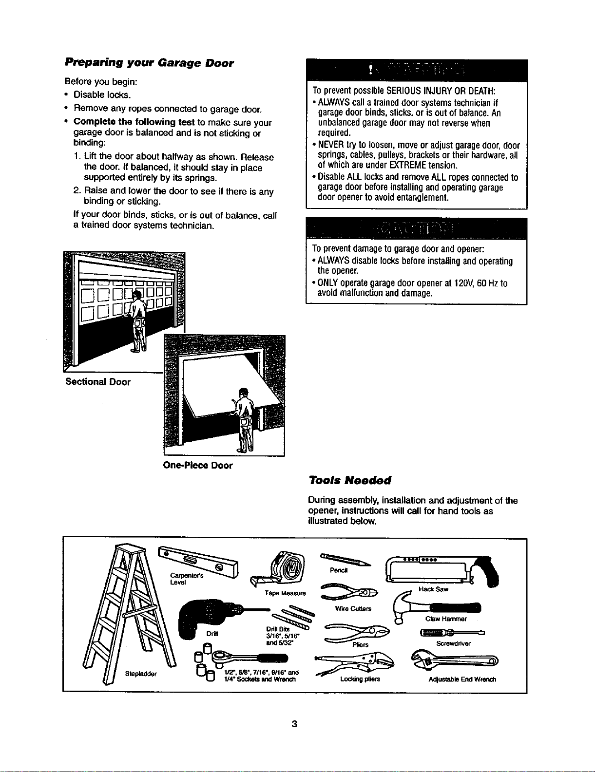
Preparing your Garage Door
Beforeyou begin:
• Disable locks.
• Remove any ropesconnectedto garage door.
• Complete the following test to make sure your
garage door is balanced and is not stickingor
binding:
1. Liftthe door about halfwayas shown. Release
the door.If balanced, itshouldstay in place
supportedentirelyby itsspdngs.
2. Raise and lower the door to see ifthere is any
bindingor sticking.
If yourdoor binds,sticks,or isout of balance, cell
a trained door systemstechnician.
TopreventpossibleSERIOUSINJURYORDEATH:
• ALWAYScalla traineddoorsystemstechnicianif
garagedoorbinds,sticks,or isoutofbalance.An
unbalancedgaragedoormaynotreversewhen
required.
• NEVERtryto loosen,moveoradjust garagedoor,door
springs,cables,pulleys,bracketsor theirhardware,all
ofwhichareunderEXTREMEtension.
• DisableALLlocksandremoveALLropesconnectedto
garagedoorbeforeinstallingandoperatinggarage
dooropenertoavoidentanglement.
Topreventdamagetogaragedoorandopener:
• ALWAYSdisablelocksbeforeinstallingandoperating
theopener.
• ONLYoperategaragedooropenerat 120V,60 Hzto
avoidmalfunctionanddamage.
Sectional Door
One-Piece Door
Tools Needed
During assembly, installationand adjustmentof the
opener,instructionswillcall for hand toolsas
illustratedbelow.
Level
Tape Measure
Drill Bits
Dda 3/16", 5/16"
and 5/32"
1/2",5/8", 7/16", 9/16" end
LJ_ 1/4" Sockets and Wrench
PencJ
Wk'e Cutters
Screwdriver
Adjustable End Wrench
Planning
Identifythe type and height of yourgarage door.
Survey yourgarage area to see if any ofthe
conditionsbelowapply toyour installation.Additional
materialsmay be required.You may find ithelpfulto
refer backto thispage and the accompanying
illustrationsas you proceedwith the installationof
your opener.
Dependingon your requirements,there are several
installationstepswhichmay call for materialsor
hardware not includedin the carton.
• InstallationStep 1 - Lookat the wall or ceiling
above the garage door.The header bracket must
be securelyfastened to structuralsupports.
• InstallationStep 5 - Do you have a finishedceiling
in yourgarage? If so, a supportbracket and
additionalfastening hardware may be required.
• InstallationStep 10- Depending upongarage
construction,extensionbrackets or woodblocks
may be needed to installsensors.
• InstallationStep 10 -Alternate floor mountingof
the safety reversingsensorwillrequirehardware
not provided.
Do you have an access door in additionto the
garage door? If not, Model 53702 Emergency Key
Release is required.See Acoessodes page.
Lookat the garage door where itmeets the floor.
Any gap between the floor and the bottomof the
door must notexceed 1/4". Otherwise, the safety
reversal system may notwork properly.See
AdjustmentStep 3. Flooror door shouldbe
repaired.
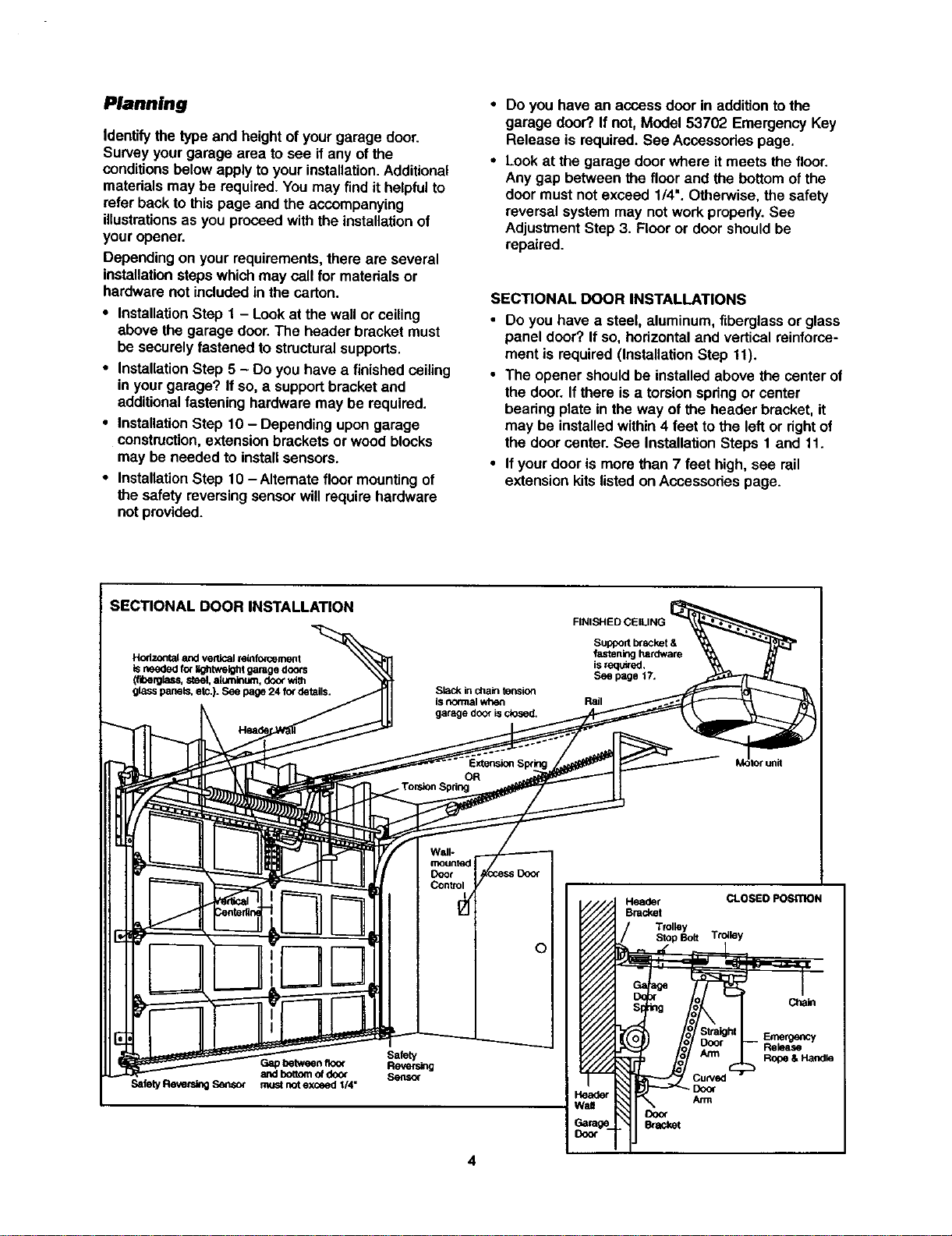
SECTIONAL DOOR INSTALLATIONS
• Do you have a steel, aluminum, fiberglassor glass
panel door? Ifso, horizontaland verticalreinforce-
ment is required (InstallationStep tl).
• The opener shouldbe installedabove the center of
the door.If there isa torsionspdng or center
beadng plate in the way of the header bracket,it
may be installedwithin4 feet to the left or rightof
the door center.See InstallationSteps 1 and 11.
• Ifyour door is more than 7 feet high, see rail
extensionkitslistedon Accessories page.
SECTIONAL DOOR INSTALLATION
Hodz.ordalendverticalreinforcement
isneededforI_htweightgaragedoors
(fiberglass,steel,aluminum,doorwith
glasspanels,etc.).Seepage24fordetails.
Slack in chain fension
ISnormal when
garage door isclosed.
FINISHED CEILING
Suppod Ixacket &
fastening hardware
is requ_ed,
See page 17.
Rail
Wall-
mounted
Door
Control V
Gap between floo_
aed bottomof door
Safety Reve_g Sensor must not exceed I/4"
Safety
Reversing
Sensor
Header CLOSED POSITION
Bracket
Trolley
Stop Bolt Trolley
Chale
Emergency
Release
Rope & Handle
_Door
Arm
Door
Bracket
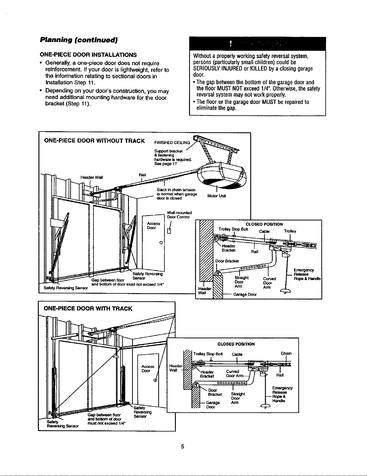
Planning (continued)
ONE-PIECE DOOR INSTALLATIONS
• Generally,a one-piece door does not require
reinforcement.If your door is lightweight,refer to
the informationrelatingto sectional doorsin
InstallationStep 11.
• Depending on your door's construction,you may
need additionalmountinghardware for the door
bracket (Step 11).
Withouta properlyworkingsafetyreversalsystem,
persons(particularlysmallchildren)couldbe
SERIOUSLYINJUREDor KILLEDbya closinggarage
door
•Thegapbetweenthebottomofthegaragedoor and
thefloor MUSTNOTexceed1/4".Otherwise,thesafety
reversalsystemmaynotworkproperly.
•Thefloor orthegaragedoorMUSTberepairedto
eliminatethegap.
ONE-PIECE DOOR WITHOUT TRACK
Rail
Header Wail
FINISHED CEILING
Supportbracket
& fastening
hardware isrequk'ab.
See page 17
Slack inchain ter_sinn
isnormal when garage
door isclosed
Motor Unit
Wall-mounted
Door Control
,cc.s
DOOr
o
Safety Reversing Sensor
.----.__.__
Safety Reversing
Gap between floor Sensor
and bottom of door must not exceed 1/4"
ONE-PIECE DOOR WITH TRACK
eDd_r
/all
CLOSED POSITION
Trolley Stop Bolt
I Cable Trolley
Emergency
. Release
Curved R_oe & HaiKIle
Door
Arm
CLOSED POSITION
Trolley Stop Bolt Cable Chain
ReversingSensor
%
Reversing
Gapbetwee_floor Sensor
and boBom o_doo_
must not exceed 1/4"
Curved
Dracket Rail
Bracket Straight
Co<x
Door
Emmgency
Rek_se
Handle
5
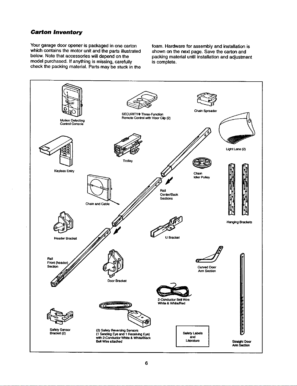
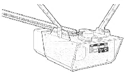
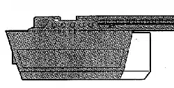
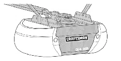
Carton Inventory
Yourgarage door opener is packaged in one carton
which containsthe motorunitand the parts illustrated
below. Note that accessodes willdepend on the
modelpurchased. If anythingismissing,carefully
check the packing material. Parts may be stuck inthe
foam. Hardware for assembly and installationis
shownon the next page. Save the carton and
packing materialuntil installationand adjustment
is complete.
Motion Oetectl_l
Co_trol Consok3
Ke_ess EnW
Header Bracket
SafetySensor
Bracket{2)
SECURITY'IP Three-Func6on
Remote Control with Visor Clip (2)
Trolley
Ctlaio
Idler Pulley
Door Bracket
=%
(2) Safety Reversing S6_sors
(1 Sending Eye and 1 Receiving Eye)
wi_ 2-Co_luctor Wllite& White/IBiaCk
8el Wire attached
2_rKlucto_ BellWire
White & White/Red
SafetyandLabels I
LJtenMure
Light Lens (2)
Hanging _ackets
sua_t Door
/um Sectk_
6
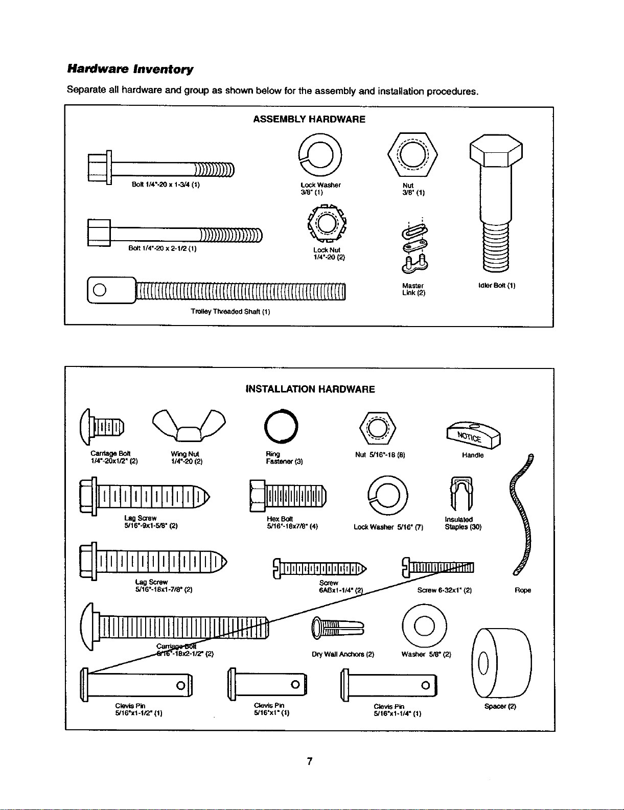
Hardware Inventory
Separate all hardware and groupas shownbelow forthe assembly and installationprocedures.
I---!, ))))))))))))))))))
Bolt 1/4%20 x 2-1/2 (1)
ASSEMBLY HARDWARE
© ©
Lock Washer Nut
3/8" (1) 3/8"(1)
o
Lock Nut
1/4"-20 (2)
_(((((((((((((((((((((('('('('((((((((((('('('('('('('(('((l(((((r('('('('(i
Trolley Threaded Shaft (1)
Master
Link (2)
tdler Bolt (1)
INSTALLATION HARDWARE
0 @
Carriage Boit Wing Nut Ring Nut 5/16"-18 (8)
114"-20xl/2" (2) 114"-20 (2) FaStener (3)
_lllllllllllllllllll_
L_ Screw
5,'16"-9xi-5/8" (2)
Hex Bo4t
5/16"- 18x7/_" (4)
©
LockWashar 5/16" (7)
Handle
Insulated
Staples (3O)
Screw 6-32xl" (2)
I
Rooe
oU
Clevis Pin
5/16"x1-1/2" (1)
[2) Dry Wall Anchors (2) Washer ,5_" (2)
Clevis Pin Clevis Pin
5,'16"xl" 111 5/16"x1-1/4" (11
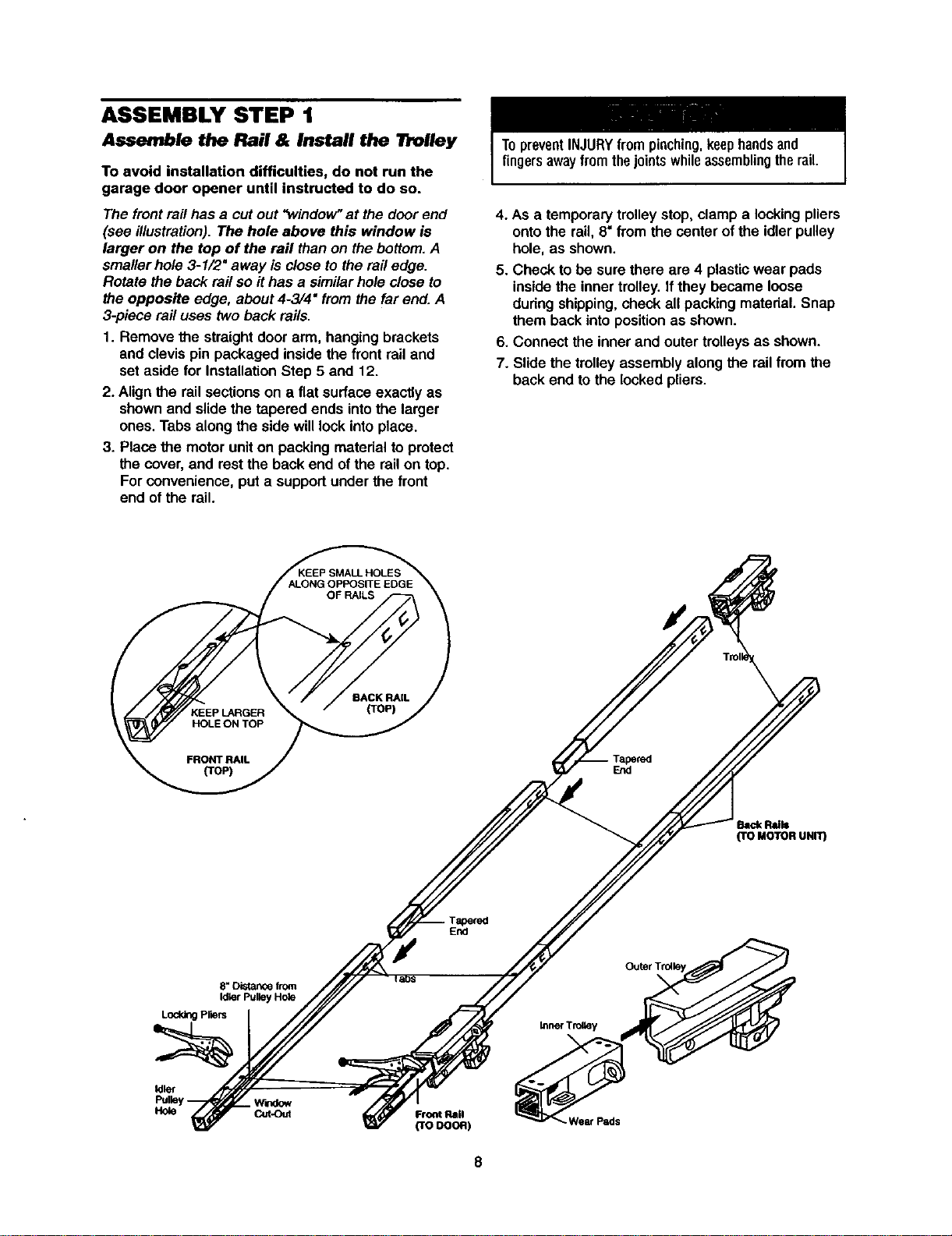
ASSEMBLY STEP 1
Assemble the Rail & Install the Trolley
To avoid installation difficulties, do not run the
garage door opener until instructed to do so.
The frontrail has a cutout "window"atthe door end
(see illustration).The hole above this window is
larger on the top of the rail than on the bottom.A
smaller hole3-1/2" away is close to the railedge.
Rotate the back rail so it has a similarhole close to
the opposite edge, about4-3/4" from the far end.A
3-piece rail uses two back rails.
1. Remove the straightdoor arm, hangingbrackets
and clevispin packaged inside the frontrail and
set aside for InstallationStep 5 and 12.
2. Align the railsectionson a flat surfaceexactly as
shownand slidethe tapered ends intothe larger
ones. Tabs along the side willlock intoplace.
3. Placethe motoruniton packingmaterialto protect
the cover,and restthe back end of the railon top.
Forconvenience, put a supportunder the front
end of the rail.
TopreventINJURYfrompinching,keephandsand
fingersawayfromthejointswhileassemblingtherail.
4. As a temporarytrolley stop,clamp a lookingpliers
ontothe rail, 8"from the center of the idler pulley
hole, as shown.
5. Check to be sure there are 4 plasticwear pads
insidethe inner trolley.If they became loose
during shipping,check all packing material. Snap
them backinto positionas shown.
6. Connect the inner and outer trolleysas shown.
7. Slidethe trolleyassembly along the railfrom the
back end to the locked pliers.
End
hick R'=I=
(TO MOTOR UNIT)
Tapered
End
e, Distance from
Ididr Pulley H(_e
Lodd_ P,ars
Idler
_lrtdow
Hole Cut-Out
Front Rail
(reoooR)
Wear Pads
8
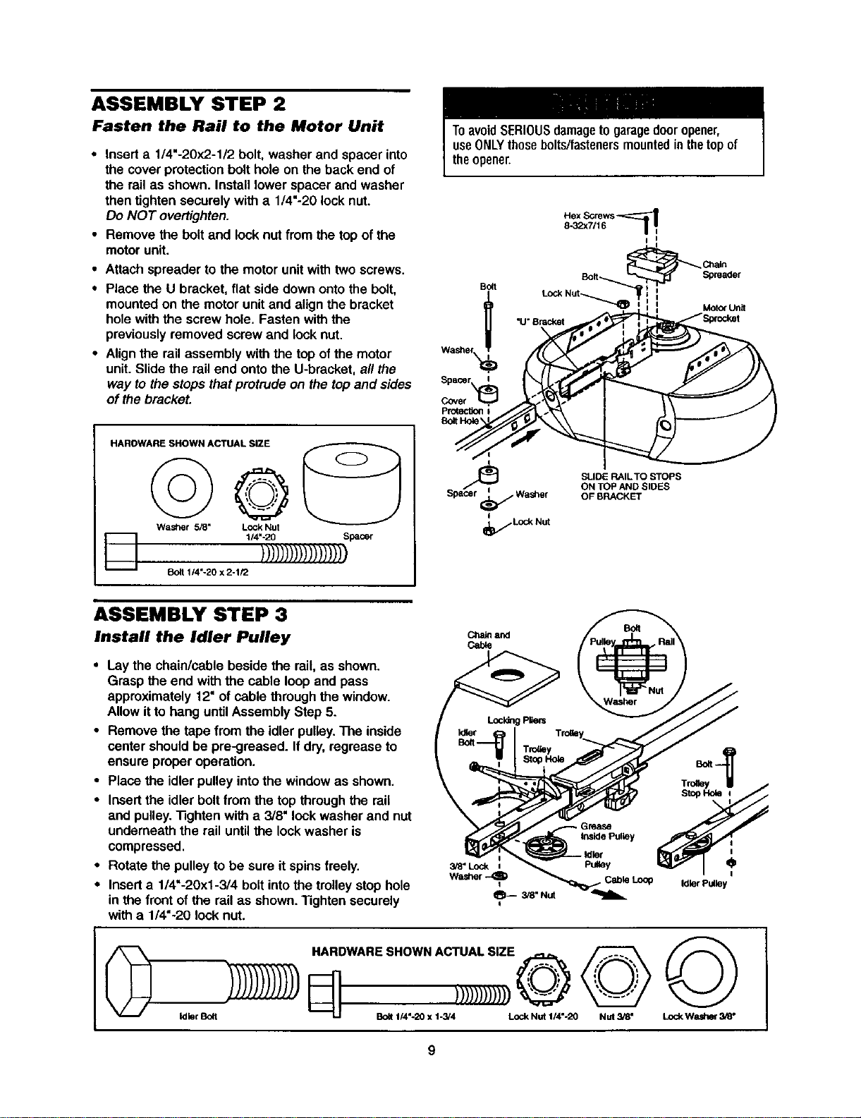
ASSEMBLY STEP 2
Fasten the Rail to the Motor Unit
• Insert a 1/4"-20x2-1/2 bolt, washer and spacerinto
the cover protection bolt hole on the back end of
the rail as shown. Install lower spacer and washer
then tighten securely with a 1/4"-20 lock nut.
Do NOT overtighten.
• Remove the bolt and lock nut from the top of the
motor unit.
• Attach spreader tothe motorunitwith twoscrews.
• Place the U bracket, flat side down ontothe bolt,
mountedon the motor unitand align the bracket
holewith the screwhole. Fasten with the
previouslyremoved screw and lock nut.
• Alignthe rail assembly with the top ofthe motor
unit. Slidethe railend ontothe U-bracket, al/the
way to the stops thatprotrude on the topand sides
of the bracket.
HAROWARE SHOWN ACTUAL SIZE
D
©
Washer 5_" Lock Nut
1/4"-20 Spacer
)))1))))))))))))))
1/4"-20 x 2-1/2
ToavoidSERIOUSdamageto garagedooropener,
useONLYthosebolts/fastenersmountedinthetopof
theopener.
Bo_I
I
I
_ Ctnain
Bolt-.._ Spreader
=
_r_)_ LOCkNut -......,_ : MOtOrUnit
__Spacer Ii
SLIDE RAIL TO STOPS
ON TOP AND SIDES
Spacer _ Wasi3er OF BRACKET
I
_f Lod_ Nut
ASSEMBLY STEP 3
Install the Idler Pulley
• Laythe chain/cable beside the rail, as shown.
Grasp the end with the cable loop and pass
approximately 12" of cable through the window.
Allow it to hang untilAssemblyStep 5.
• Remove the tape from the idler pulley.The inside
center shouldbe pre-greased. If dry,regrease to
ensure properoperation.
• Place the idler pulley intothe windowas shown.
• Insertthe idler boltfrom the top throughthe rail
and pulley."13ghtenwitha 3/8" lockwasher and nut
underneath the railuntil the lock washer is
compressed.
• Rotate the pulley to be sure it spinsfreely.
• Inserta 1/4"-20xl-3/4 bolt intothetrolley stop hole
in the front of the rail as shown."Rghten securely
with a 1/4"-20 lock nut.
C_aleand
Cable
Grease
Inside Pulley
3/8" Lock i PuUey O
Washer
Idler Pulley
©
Idler Bolt
HARDWARESHOWNACTUALSIZE -- _ / _--_ _
LJ BOlt1/4 -20 X 1-3/4 Lock Nut 114"-20 NUt 3/8" LockWasher 3/8"
9
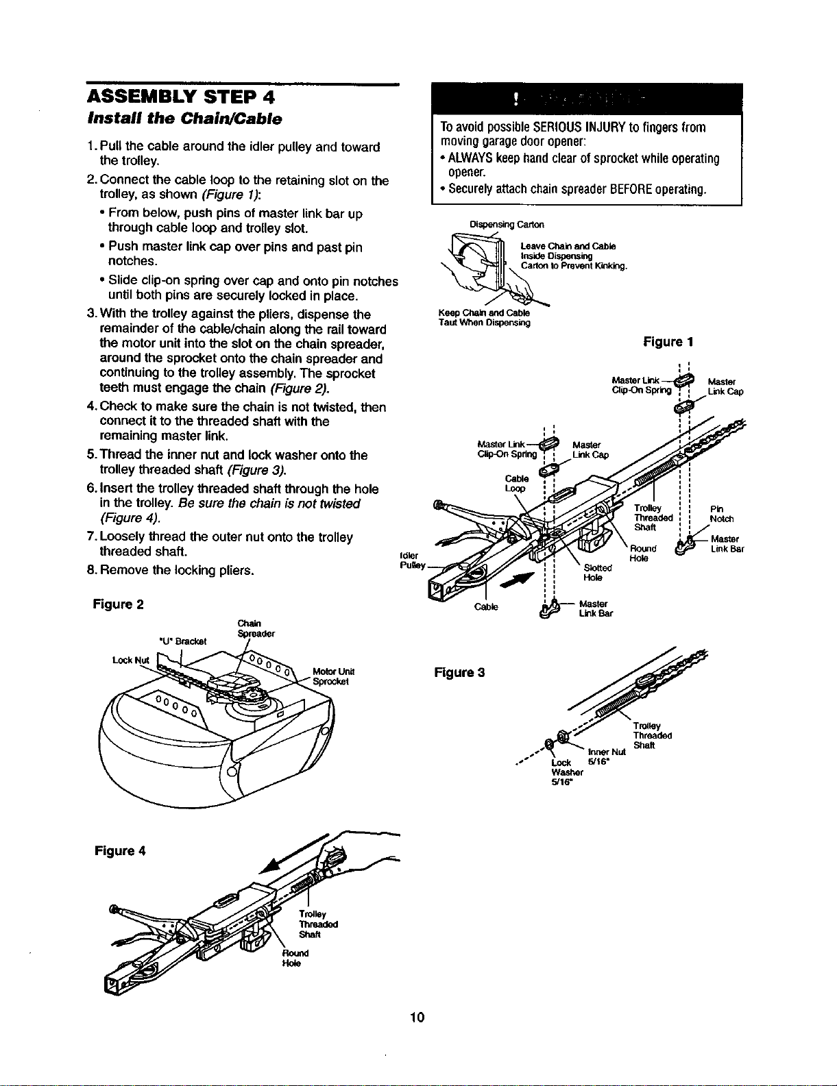
ASSEMBLY STEP 4
Install the Chain/Cable
1.Pull the cable aroundthe idler pulley and toward
the trolley.
2. Connect the cable loop tothe retainingsloton the
trolley,as shown (Figure 1):
• From below, push pinsof masterlinkbar up
through cable loopand trolleyslot.
• Push master linkcap over pinsand past pin
notches.
• Slide clip-onspringover cap and ontopinnotches
until both pins are securely locked in place.
3.With the trolley against the pliers,dispense the
remainder of the cable/chain along the rail toward
the motor unitinto the slot on the chainspreader,
around the sprocketonto the chain spreader and
continuing to the trolley assembly. The sprocket
teeth must engage the chain (Figure 2).
4.Check to make sure the chain is not twisted, then
connect it to the threaded shaft with the
remaining master link.
5.Thread the inner nut and lock washer onto the
trolley threaded shaft (Figure 3).
6. Insert the trolley threaded shaft through the hole
in the trolley. Be sure the chainis not twisted
(Figure 4).
7. Loosely thread the outer nut onto the trolley
threaded shaft.
8. Remove the locking pliers.
Idler
Figure 2
"U"Bracket
Cha_
Motorunit
"Sprocket
ToavoidpossibleSERIOUSINJURYtofingers from
moving garagedooropener:
•ALWAYSkeephandclearof sprocketwhileoperating
opener.
• SecurelyattachchainspreaderBEFOREoperating.
Dispensing Carton
Leave Chain and Cable
Inside OLspens_g
te Prevent Kinking.
Keep Chain and Cable
Taut When Dispensing
Master
Clip-On S Link Cap
Cable
Loop
Hole
i
Cable ' Master
Link Bar
Figure 1
i I
q I
Master Link_ Master
CiipOn 8p¢ LinkCap
i
: Pin
Threaded : Notch
Shaft l_
Master
Link Bar
Hole
Figure 3
_._ Threaded
_.-"_ \ - InnerNut Shaft
.'" Lock 5/16*
Washer
.5/16"
Figure 4
Trolley
Thruded
Shaft
10
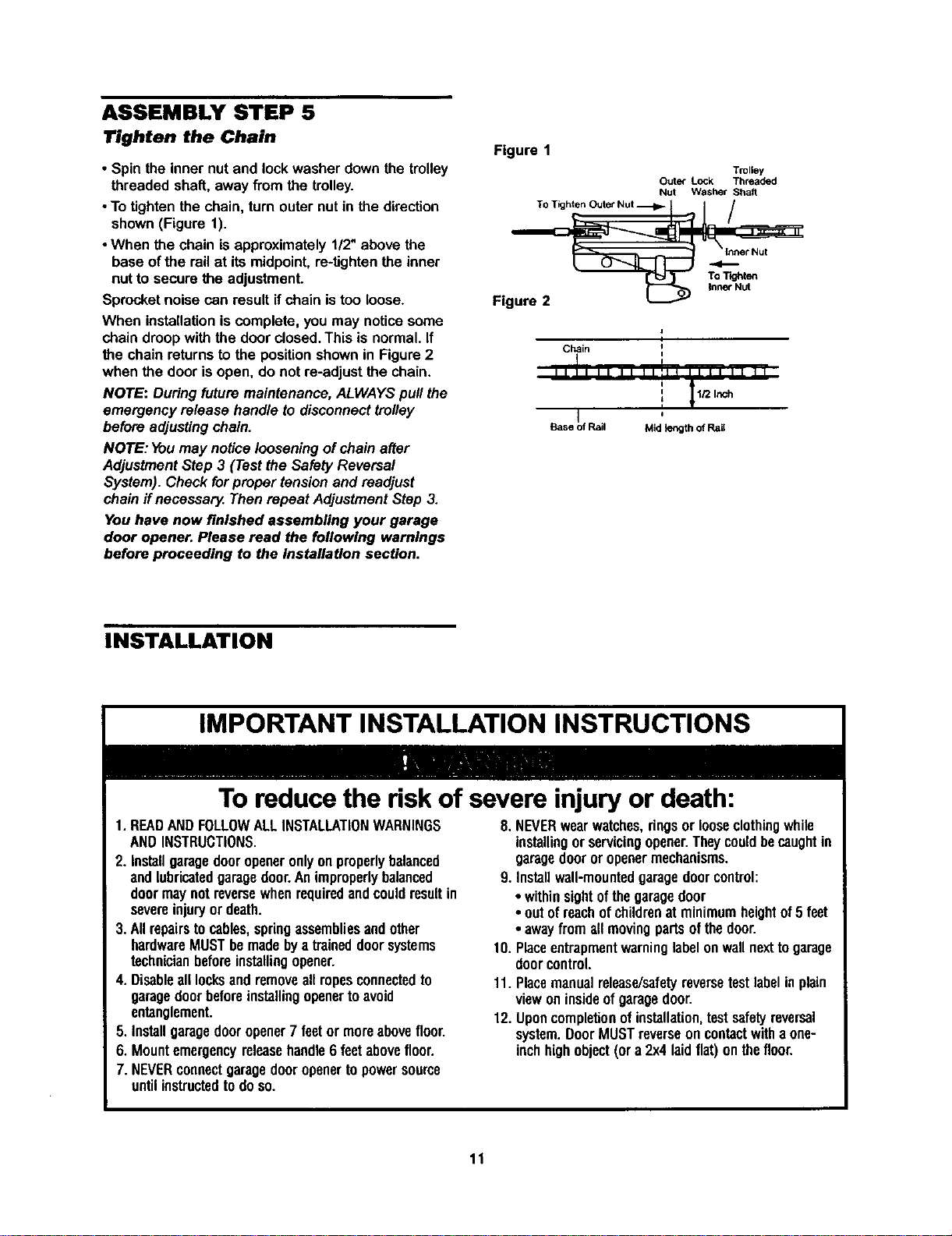
ASSEMBLY STEP 5
Tighten the Chain
• Spin the inner nut and lockwasher down the trolley
threaded shat_,away from the trolley.
• To tighten the chain, turn outernut in the direction
shown(Figure 1).
•When the chain is approximately112"above the
base ofthe railat itsmidpoint,re-tightenthe inner
nut to secure the adjustment.
Sprocketnoise can resultifchain is too loose.
When installationiscomplete, you may noticesome
chain droopwiththe door closed.Thisis normal.If
the chain returnsto the positionshownin Figure2
when the door isopen, do not re-adjust the chain.
NOTE: Duringfuture maintenance,ALWAYSpull the
emergency release handle to disconnecttrolley
before adjustingchain.
NOTE: Youmay noticelooseningofchain after
AdjustmentStep 3 (Testthe Safety Reversal
System). Check forproper tensionand readjust
chainif necossary.Then repeat AdjustmentStep 3.
You have now finished assembling your garage
door opener. Please read the following warnings
before proceeding to the Installation section.
Figure 1
Trolley
Outer Lock Threaded
Nut Washer Shaft
Figure 2
Chain i
II ]1 II II Ilill II II II
: _ 1/2 Inch
f
I
,
Base Rail Mid length of Rail
I I
INSTALLATION
IMPORTANT INSTALLATION INSTRUCTIONS
To reduce the risk of severe injury or death:
1.READANDFOLLOWALLINSTALLATIONWARNINGS
ANDINSTRUCTIONS.
2. Installgaragedooropeneronlyon properlybalanced
and lubricatedgaragedoor.Animproperlybalanced
doormaynotreversewhenrequiredandcouldresultin
severeinjuryor death.
3.All repairstocables,springassembliesandother
hardwareMUSTbemadebya traineddoorsystems
technicianbeforeinstallingopener.
4. Disableall locksandremoveallropesconnectedto
garagedoorbeforeinstallingopenertoavoid
entanglement.
5. Installgaragedooropener7 feetor moreabovefloor.
6. Mountemergencyreleasehandle6 feetabovefloor.
7. NEVERconnectgaragedooropenertopowersource
untilinstructedtodoso.
8.NEVERwearwatches,ringsor looseclothingwhile
installingor servicingopener.Theycouldbecaughtin
garagedooror openermechanisms.
9. Installwall-mountedgaragedoorcontrol:
• withinsightofthegaragedoor
• outofreachofchildrenat minimumheightof5 feet
• awayfrom all movingpartsofthedoor.
10. Placeentrapmentwarninglabelonwallnexttogarage
doorcontrol.
11. Placemanualrelease/safetyreversetestlabelinplain
viewoninsideofgaragedoor.
12. Uponcompletionofinstallation,testsafetyreversal
system.DoorMUSTreverseoncontactwitha one-
inchhighobject(or a 2x4laid flat)onthefloor.
11
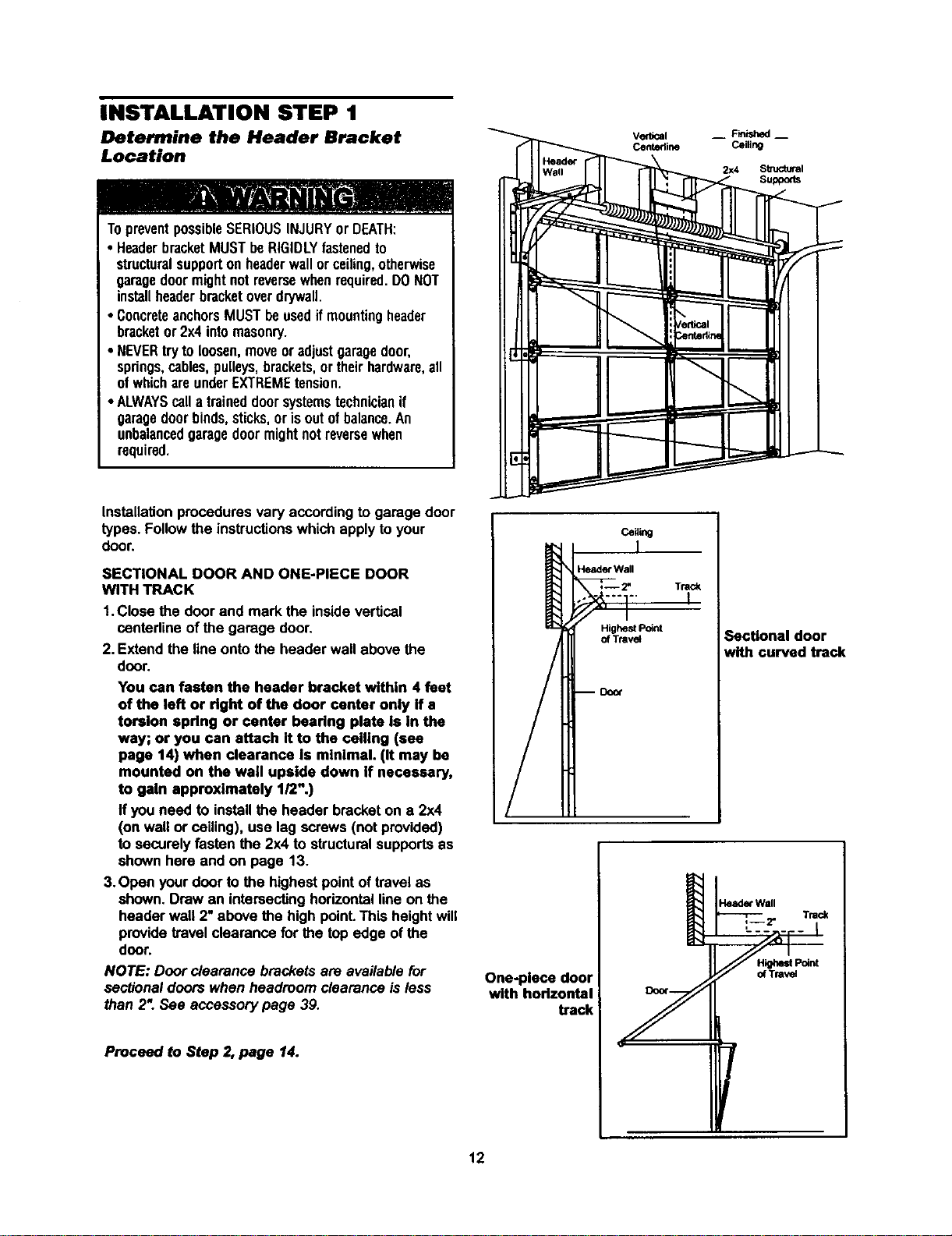
INSTALLATION STEP 1
Determine the Header Bracket
Location
TopreventpossibleSERIOUSINJURYor DEATH:
• HeaderbracketMUSTbeRIGIDLYfastenedto
structuralsupportonheaderwallorceiling,otherwise
garagedoormightnotreversewhenrequired.DONOT
installheaderbracketoverdrywall.
• ConcreteanchorsMUSTbeusedifmounting header
bracketor2x4 intomasonry.
• NEVERtryto loosen,moveoradjustgaragedoor,
springs,cables,pulleys,brackets,or theirhardware,all
ofwhichareunderEXTREMEtension.
• ALWAYScalla traineddoorsystemstechnicianif
garagedoorbinds,sticks,orisoutofbalance.An
unbalancedgaragedoormightnot reversewhen
required.
Installation procedures vary according to garage door
types. Follow the instructions which apply to your
door.
SECTIONAL DOOR AND ONE-PIECE DOOR
WITH TRACK
1.Close the door and mark the insidevertical
centerlineof the garage door.
2. Extend the line onto the header wall above the
door.
You can fasten the header bracket within 4 feet
of the left or right of the door center only If a
torsion spdng or center bearing plate is in the
way; or you can attach It to the ceiling (see
page 14) when clearance is minimal. (It may be
mounted on the wall upside down if necessary,
to gain approximately 1/2".)
If you need to installthe header bracketon a 2x4
(on wall or ceiling), use lag screws (not provided)
to securelyfasten the 2x4 to structuralsupportsas
shown here and on page 13.
3.Open your door to the highest pointof travel as
shown. Draw an intersectinghorizontal lineon the
header wall 2" above the high point.This heightwill
providetravel clearance for the top edge of the
door.
NOTE: Door clearance brackets are availablefor
sectionaldoors when headroom clearance is less
than 2". See accessory page 39.
Proceed to Step 2, page 14.
Header Wall
Highest Point
of Ttavst
Trac_
Sectional door
with curved track
One-piece door
with horlzontal
track
12
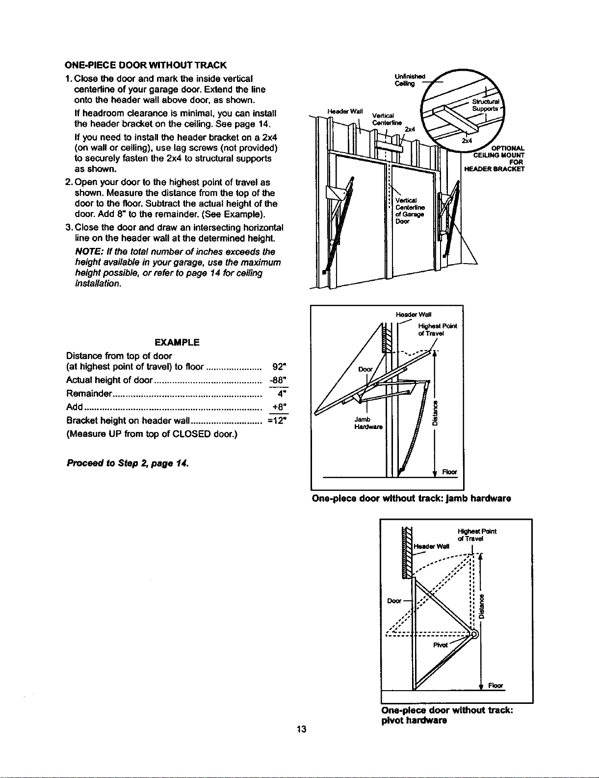
ONE-PIECEDOORWITHOUTTRACK
1.Closethedoorandmarkthe insidevertical
centadine of yourgarage door.Extend the line
onto the header wall above door,as shown.
If headroom clearance is minimal, you can install
the header bracket on the ceiling. See page 14.
If you need to install the header bracket on a 2x4
(on wall or ceiling), use lag screws (not provided)
to securely fasten the 2x4 to structural supports
as shown.
2. Open your door to the highest point of travel as
shown. Measure the distance from the top of the
door to the floor. Subtract the actual height of the
door. Add 8" to the remainder. (See Example).
3.Close the door and draw an intersecting horizontal
line on the header wall at the determined height.
NOTE: ff the total number of inches exceeds the
height available in your garage, use the maximum
height possible, or refer to page 14 for ceiling
installation.
VerUcst
Centedine
2x4
FOR
HEADER BRACKET
EXAMPLE
Distancefrom top of door
(at highest pointof travel)to floor...................... 92"
Actualheight of door.......................................... -88"
Remainder.......................................................... 4"
Add..................................................................... +8"
Bracketheight on header wall............................ =12"
(Measure UP from top of CLOSED door.)
Proceed to Step 2,page 14.
Header Wall
J
HighestPoint
of Tr=vst
One-piece door without track: jamb hardware
Highest Point
of Travel
Header Wall
Fkxx
One-piece door without track:
pivot hardware
13
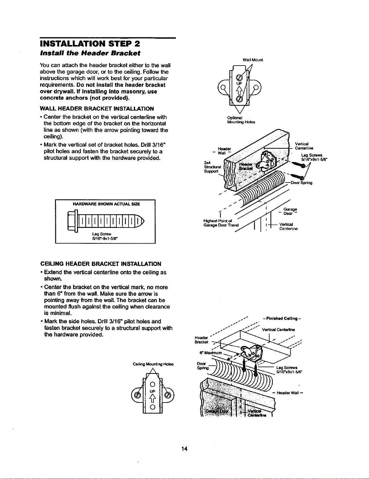
INSTALLATION STEP 2
Install the Header Bracket
You can attach the header bracket either to the wall
above the garage door, or to the ceiling. Follow the
instructions which will work best for your particular
requirements. Do not install the header bracket
over drywall. If installing into masonry, use
concrete anchors (not provided).
WALL HEADER BRACKET INSTALLATION
• Center the bracket on the verticalcentadinewith
the bottomedge of the bracketon the horizontal
line as shown (with the arrow pointingtowardthe
ceiling).
• Mark the verticalset of bracketholes. Ddll 3/16"
pilotholes and fastenthe bracket securelyto a
structuralsupportwith the hardware provided.
Wall Mount
Optional
Mounting Hole_
2)(4
Sb_mturai
Suppo_
Vedk_l
Centedlne
Lag Screws
5/16"xgx1-SJS"
HAROWARE SHOWN ACTUAL SiZE
lll IIIIIlllllIJl
Lag Screw
5/16"-9x1-518"
/
/
Highest Point of
Garage Door Travel
Garage
Centedine
CEIUNG HEADER BRACKET INSTALLATION
• Extend the verticalcenterline ontothe ceilingas
shown.
• Center the bracket on the vertical mark, no more
than 6"from the wall.Make sure the arrowis
pointing away from the wall. The bracket can be
mounted flush againstthe ceilingwhen clearance
is minimal.
• Mark the side holes. Drill3/16" pilotholesand
fasten bracket securelyto a structuralsupportwith
the hardware provided.
I
Heade_ _
Bracket
Door
Sp_ng
- Finished Celllng -
5/16"xgx1-5/8"
14
Header Bracket
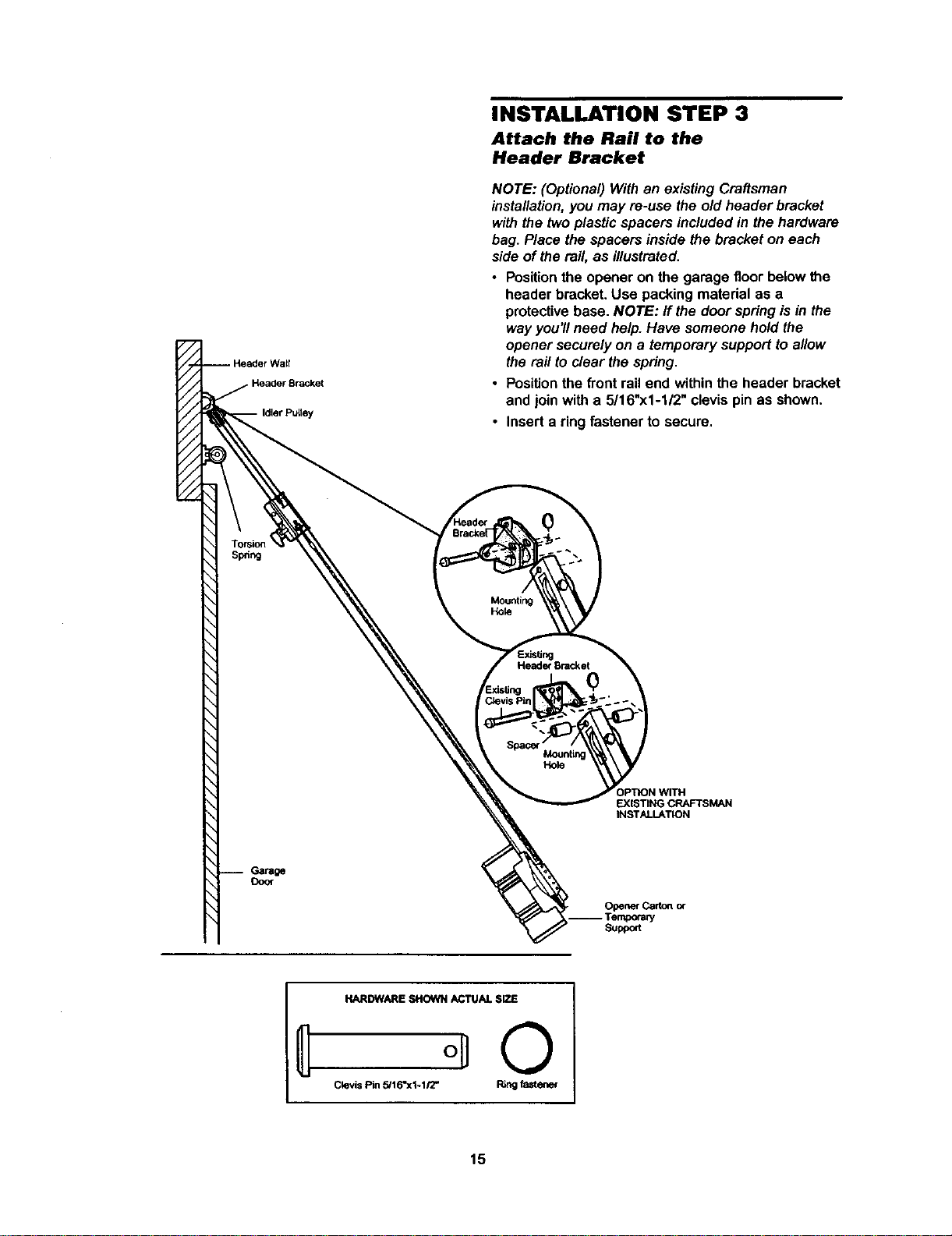
INSTALLATION STEP 3
Attach the Rail to the
Header Bracket
NOTE: (Optional)Withan existing Craftsman
installation,you may re-use the old header bracket
withthe twoplasticspacers includedin thehardware
bag. Place the spacers inside the bracket on each
side of the rail, as illustrated.
• Positionthe opener on the garage floor belowthe
header bracket.Use packing material as a
protectivebase. NOTE: If the door springisin the
way you'llneed help. Have someonehold the
opener securelyon a temporary supportto allow
the rafttoclear the spring.
• Positionthe frontrail end withinthe header bracket
and join with a 5/16"x1-1/2" clevispin as shown.
• Inserta ring fastener to secure.
Mounting
Hole
Header Bracket
Mounting
Hole
EXISTING CRAFTSMAN
INSTALLATION
Door
OpenerCart_ of
Suppeft
HARDWARE SHOWN ACTUAL SIZE
Clevis Pin 5/16"x1-1/2" Ring fastener
15
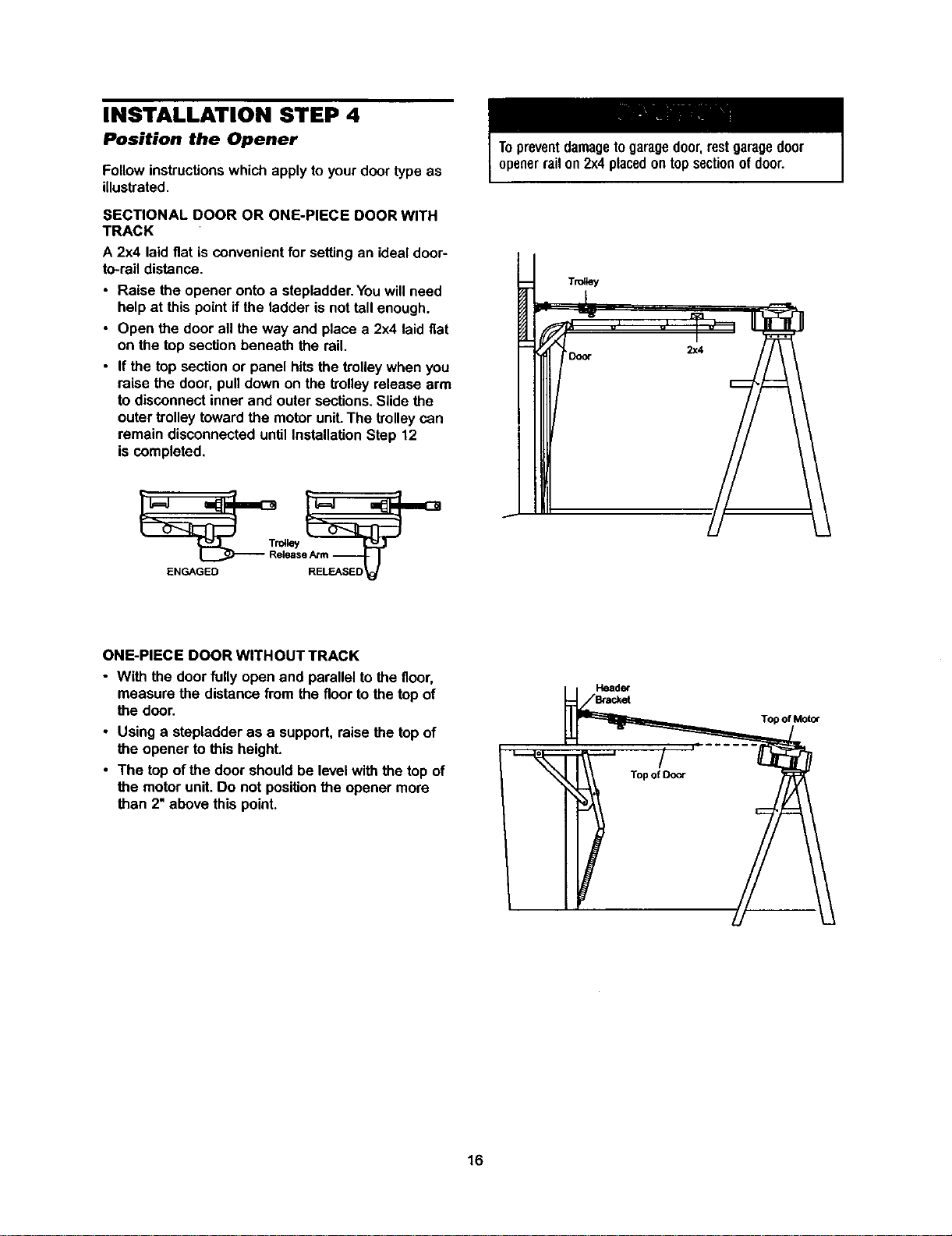
INSTALLATION STEP 4
Position the Opener
Follow instructions which apply to your door type as
illustrated.
SECTIONAL DOOR OR ONE-PIECE DOOR WITH
TRACK
A 2x4 laidflat is convenientfor settingan idealdoor-
to-rail distance.
• Raise the opener onto a stepladder You will need
help at this point if the ladder is not tall enough.
• Open the door all the way and place a 2x4 laid flat
on the top section beneath the rail.
• If the top section or panel hits the trolley when you
raise the door, pull down on the trolley release arm
to disconnect inner and outer sections. Slide the
outer trolley toward the motor unit. The trolley can
remain disconnected until Installation Step 12
is completed
Topreventdamagetogaragedoor,restgaragedoor
openerrailon2x4placedontopsectionofdoor
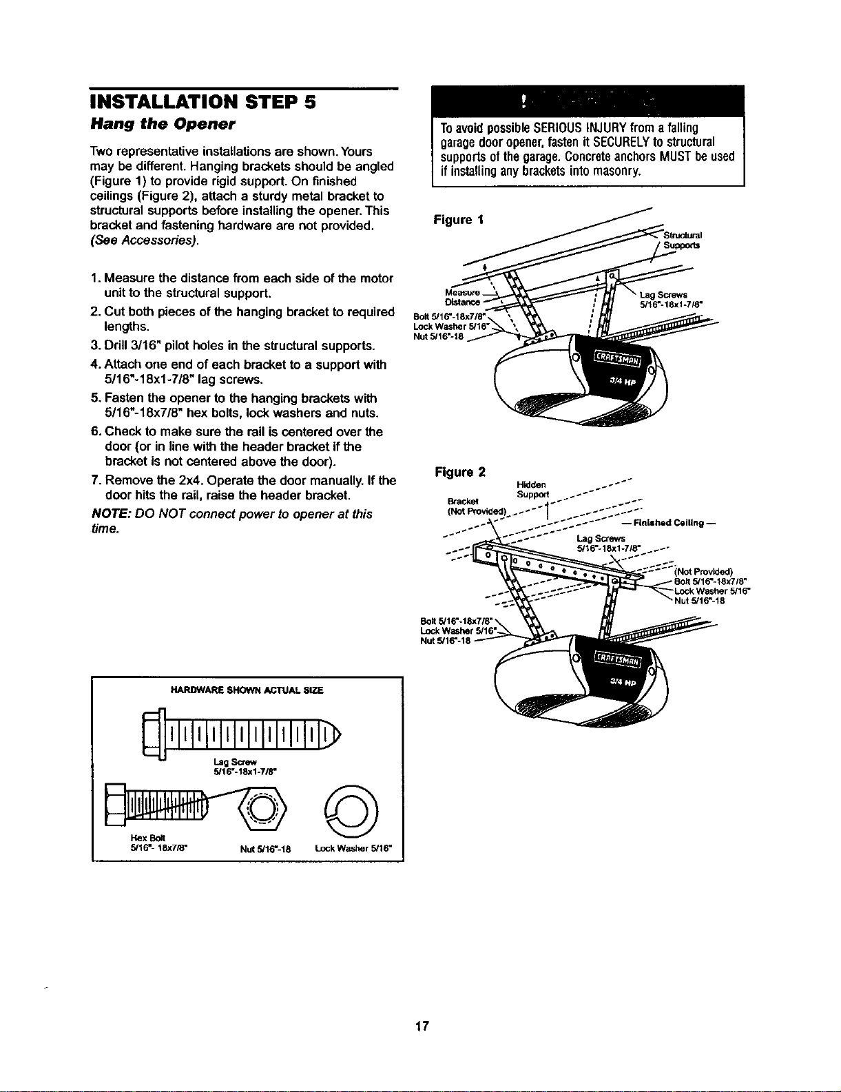
ONE-PIECE DOOR WITHOUT TRACK
• With the door fully openand parallelto the floor,
measure the distancefrom the floorto thetop of
the door.
• Using a stepladder as a support,raisethe top of
the opener to this height.
• The top of the door shouldbe levelwith the top of
the motorunit. Do not positionthe opener more
than 2"above this point.
Header
Top of Door
Top of Motor
16
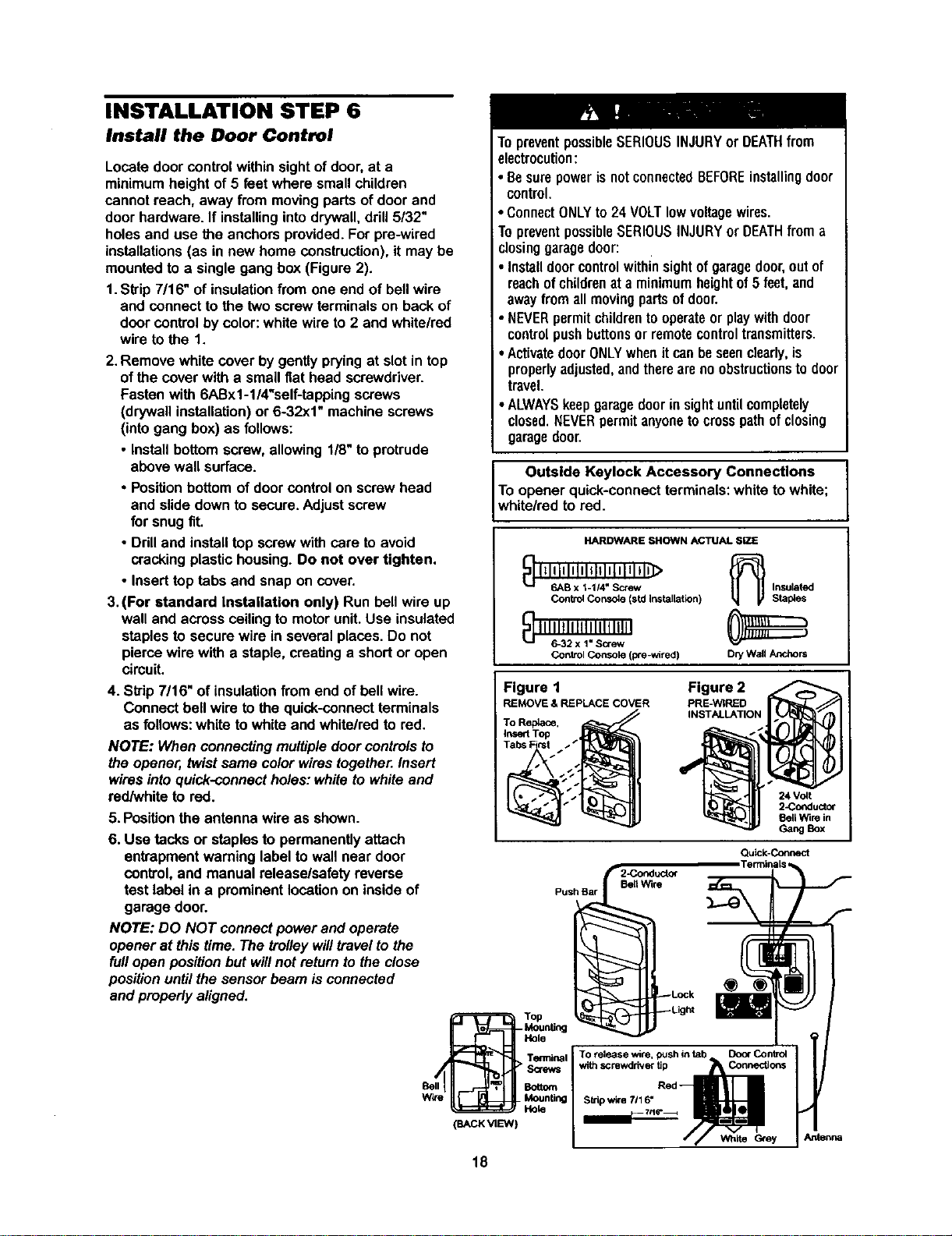
INSTALLATION STEP 5
Hang the Opener
Two representative installations are shown. Yours
may be different. Hanging brackets should be angled
(Figure 1) to provide rigid support. On finished
ceilings (Figure 2), attach a sturdy metal bracket to
structural supports before installing the opener. This
bracket and fastening hardware are not provided.
(See Accessories).
ToavoidpossibleSERIOUSINJURYfroma falling
garagedooropener,fastenitSECURELYtostructural
supportsofthegarage.ConcreteanchorsMUSTbeused
ifinstallinganybracketsintomasonry.
Figure 1
1.Measure the distancefrom each side of the motor
unitto the structuralsupport.
2. Cut bothpieces of the hanging bracketto required
lengths.
3. Drill 3/16" pilot holesin the structuralsupports.
4. Attach one end of each bracketto a supportwith
5/16"-18xl -7/8" lag screws.
5. Fasten the opener to the hangingbrackets with
5/16"-18x7/8" hex bolts,lock washers and nuts.
6. Check to make sure the rail iscentered overthe
door(or in line withthe header bracketif the
bracketis not centered above the door).
7. Remove the 2x4. Operate the door manually.Ifthe
door hitsthe rail, raise the header bracket.
NOTE: DO NOT connectpower to opener at this
time.
Bolt 5,'16"-18x718"
Nut 5/16"-18
• Lag Screws
5/16"-18xl-7/8"
Figure 2
-- Finished Ceiling --
Lag Screws
__.+ 5/16=*18xl-718 - _._"
Nut 5/16"-18
HARDWARE SHOWN ACTUAL SIZE
5/16"-18xl-7/8"
Hex Bolt
5/16"- 18X7/8" Nut 5/16%18
©
Lock Washer 5/16"
17
INSTALLATION STEP 6
Install the Door Control
Locate door control within sight of door, at a
minimum height of 5 feet where small children
cannot reach, away from moving parts of door and
door hardware. If installing into drywall, drill 5/32"
holes and use the anchors provided. For pre-wired
installations (as in new home construction), it may be
mounted to a single gang box (Figure 2).
1. Skip 7/16" of insulation from one end of bell wire
and connect to the two screw terminals on back of
door control by color: white wire to 2 and white/red
wire to the 1.
2.Remove white cover by gentlypryingat slot in top
ofthe cover with a small fiat head screwdriver.
Fasten with 6ABx1-l/4%elf-tapping screws
(drywall installation)or 6-32x1" machinescrews
(intogang box) as follows:
• Installbottomscrew, allowing 1/8"to protrude
above wall surface.
• Positionbottom of door control on screw head
and slidedown to secure.Adjust screw
for snugfit.
• Ddll and installtop screwwith care to avoid
cracking plastichousing.Do not over tighten.
• Inserttop tabs and snap on cover.
3. (For standard Installation only) Run bellwire up
wall and across ceilingto motorunit.Use insulated
staplesto secure wire in several places.Do not
piercewire with a staple,creating a shortor open
circuit.
4. Skip 7/16" of insulationfrom end of bellwire.
Connect bell wire tothe quick-connect terminals
as follows: white to white and white/redto red.
NOTE: When connecting multiple door controls to
the opener, twist same color wires together. Insert
wires into quick-connect holes: white to white and
redhNhite to red.
5. Positionthe antenna wire as shown.
6. Use tacks or staples to permanentlyattach
entrapment warninglabel to wall near door
control, and manual release/safetyreverse
test label in a prominentlocationon inside of
garage door.
NOTE: DO NOT connect power and operate
opener at thistime. The trolleywilltravelto the
fullopen positionbutwill not returnto the close
positionuntil thesensor beam is connected
and properly aligned.
To preventpossibleSERIOUSINJURYor DEATHfrom
electrocution:
• BesurepowerisnotconnectedBEFOREinstallingdoor
• control.
ConnectONLYto 24 VOLTlowvoltagewires.
TopreventpossibleSERIOUSINJURYor DEATHfroma
closinggaragedoor:
Installdoorcontrolwithinsightofgaragedoor,outof
reachof childrenat a minimumheightof5 feet,and
awayfromall movingpartsofdoor.
• NEVERpermit childrentooperateor playwithdoor
controlpushbuttonsorremotecontroltransmitters.
•ActivatedoorONLYwhenitcanbeseenclearly,is
properlyadjusted,andthereareno obstructionstodoor
travel.
• ALWAYSkeepgaragedoorinsightuntilcompletely
closed,NEVERpermitanyonetocrosspathofclosing
garagedoor.
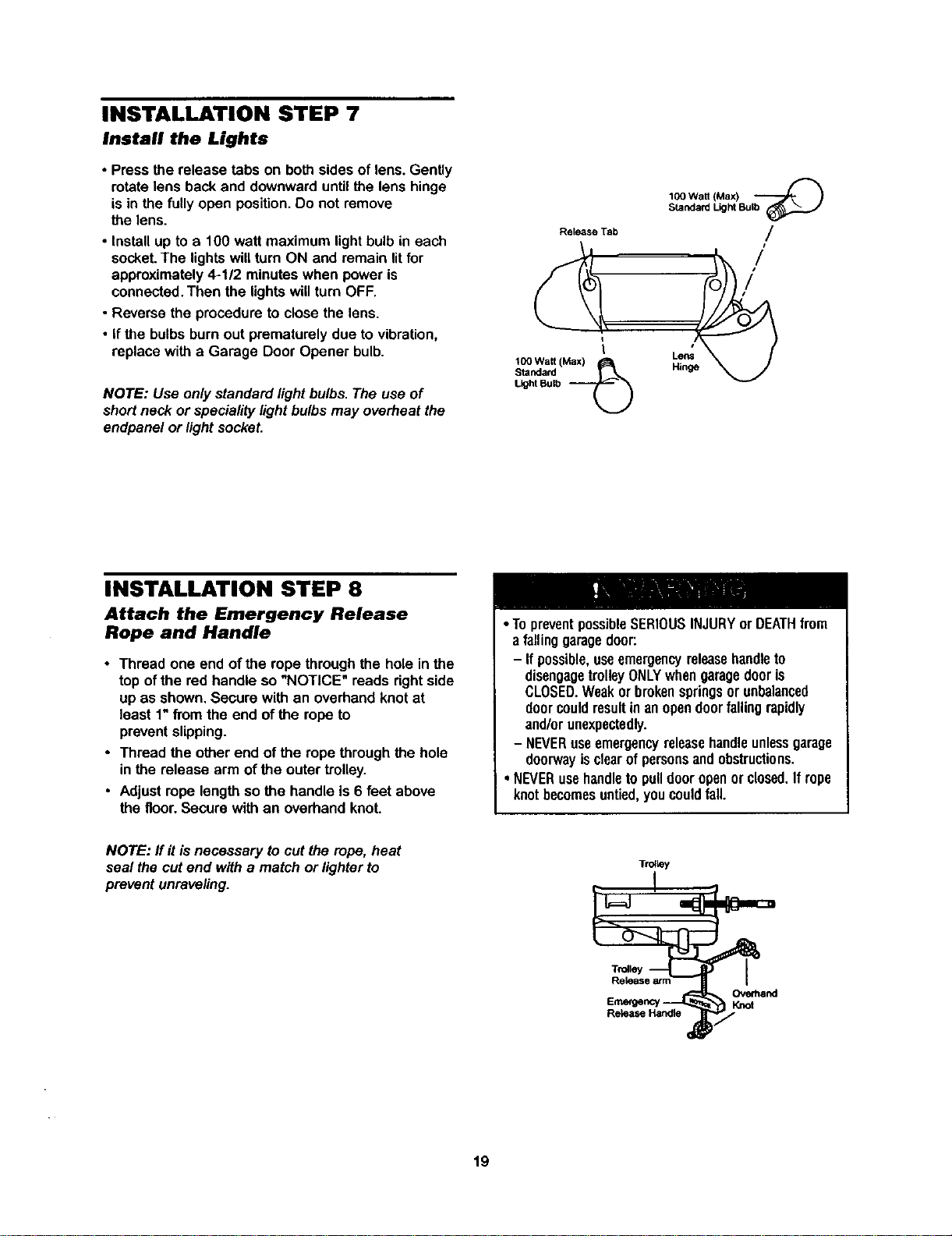
Outside Keylock Accessory Connections
To opener quick-connectterminals:white to white;
white/red tored.
HARDWARE SHOWN ACTUAL SiZE
{_I_lillltltllltltlt Ill,Ill>
6AB x 1-114"Screw Insulated
Control Console (std Installation) Staples
ContrOl Console (pre-wired) Dry Wall Anchors
Figure 1
REMOVE & REPLACE COVER
To Replace,
Insefl Top
Figure 2
PRE-WIRED
INSTALLATION
24 Volt
2-Coeductor
Sell Wire in
Gang Box
Qu_Connect
TerminaLs
2-Conducto_
Push Bar BertWire
-_ur_dng
To release wire, push intab Door Control
withscrewdriver tip Connections
Red
Strip wire 7116"
(BACK VIEW)
// White Grey J Antenna
18
INSTALLATION STEP 7
Install the Lights
• Press the release tabs on both sides of lens. Gently
rotate lens back and downward until the lens hinge
is in the fully open position. Do not remove
the lens.
• install up to a 100 watt maximum light bulb in each
socket. The lights will turn ON and remain lit for
approximately 4-1/2 minutes when power is
connected. Then the lights will turn OFF.
• Reverse the procedure to close the lens.
• If the bulbs burn out prematurely due to vibration,
replace with a Garage Door Opener bulb.
NOTE: Use only standard light bulbs. The use of
short neck or speciality light bulbs may overheat the
endpanel or light socket.
Release Tab
100 Watt (Max)
Standard
Light Bulb
IC0 Watt (Max) "--_-_ )
Standard Light Bulb
/
/
/
Lens
Hinge
INSTALLATION STEP 8
Attach the Emergency Release
Rope and Handle
• Thread one end of the rope through the hole inthe
top ofthe red handle so "NOTICE" reads rightside
up as shown. Secure with an overhandknot at
least 1"from the end of the ropeto
preventslipping.
• Thread the other end of the ropethrough the hole
inthe release arm of the outer trolley.
• Adjust rope lengthso the handle is 6 feet above
the floor.Secure with an overhandknot.
• TopreventpossibleSERIOUSINJURYorDEATHfrom
a fallinggaragedoor:
- Ifpossible,useemergencyreleasehandleto
disengagetrolleyONLYwhengaragedooris
CLOSED.Weakor brokenspringsor unbalanced
doorcouldresultin anopendoorfalling rapidly
and/orunexpectedly.
- NEVERusaemergencyreleasehandleunlessgarage
doorwayisclearofpersonsandobstructions.
• NEVERusehandletopulldooropenorclosed.If rope
knotbecomesuntied,youcouldfall.
NOTE: flit is necessary to cut the rope, heat
seal the cut end with a match or lighter to
prevent unraveling.
T_y
Ove_and
Emergency' Knot
19
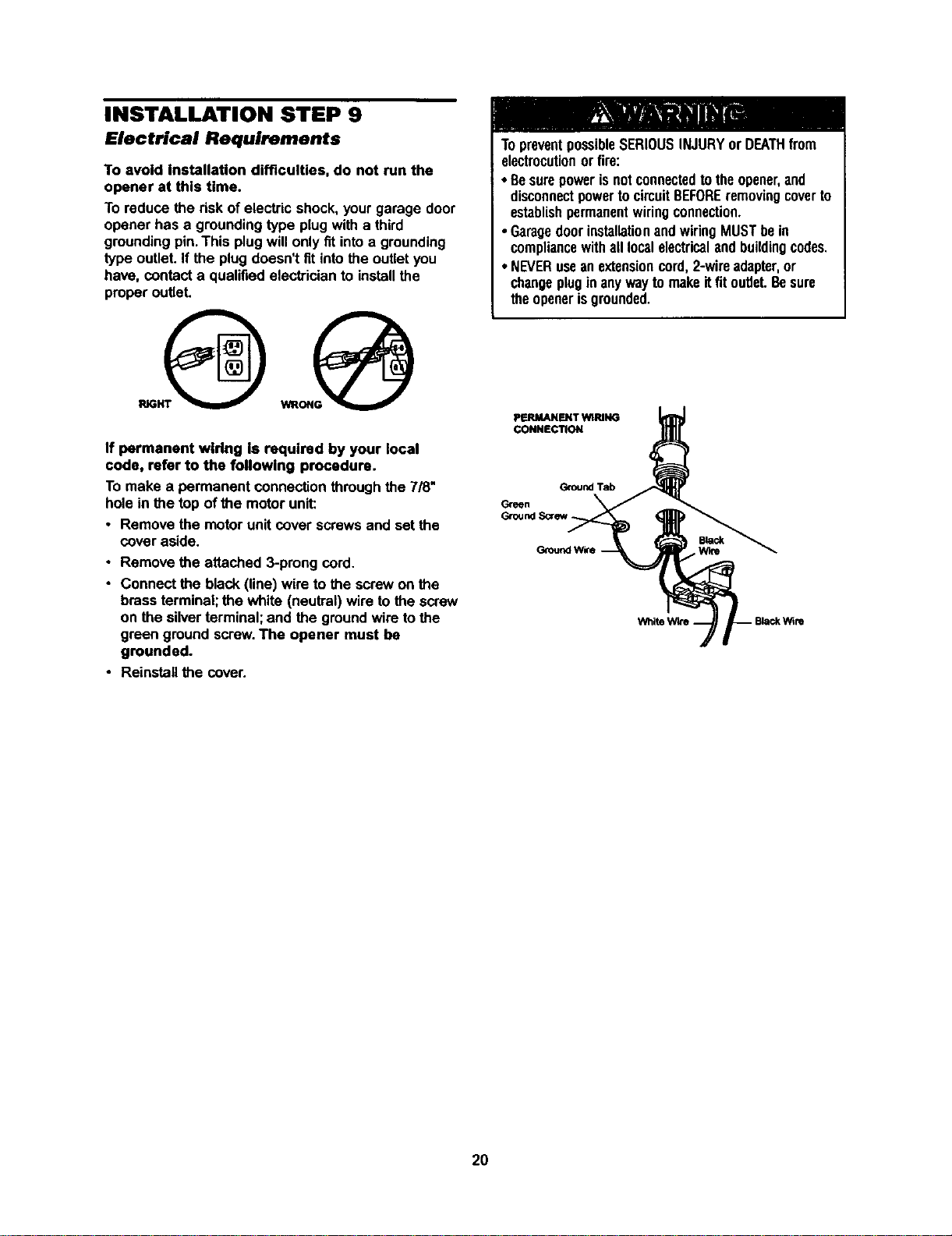
INSTALLATION STEP 9
Electrical Requirements
To avoid installation difficulties, do not run the
opener at this time.
To reduce the risk of electric shock, your garage door
opener has a grounding type plug with a third
grounding pin. This plug will only fit into a grounding
type outlet. If the plug doesn't fit into the outlet you
have, contact a qualified electrician to install the
proper outlet.
If permanent wiring Is required by your local
code, refer to the following procedure.
To make a permanent connection through the 7/8"
hole in the top of the motor unit:
• Remove the motor unit cover screws and set the
cover aside.
• Remove the attached 3-prong cord
• Connect the black (line) wire to the screw on the
brass terminal;the white (neutral) wire to thescrew
on the silverterminal; and the groundwire tothe
green ground screw The opener must be
grounded.
• Reinstallthe cover.
TopreventpossibleSERIOUSINJURYor DEATHfrom
electrocutionor fire:
• Besurepowerisnotconnectedto theopener,and
disconnectpowertocircuitBEFOREremovingcoverto
establishpermanentwiringconnection.
• GaragedoorinstallationandwiringMUSTbein
compliancewithall localelectricalandbuildingcodes
• NEVERuseanextensioncord,2-wireadapter,or
changeplugin anywaytomakeitfitoutlet Besure
theopenerisgrounded
PERMANENT WIRING
CONNECTION
GroundTab
Green
2O
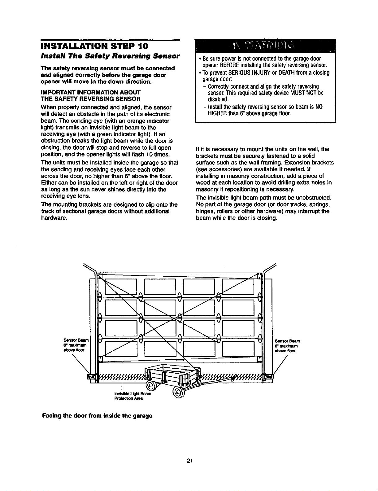
INSTALLATION STEP 10
Install The Safety Reversing Sensor
The safety reversing sensor must be connected
and aligned correctly before the garage door
opener will move in the down direction.
IMPORTANT INFORMATION ABOUT
THE SAFETY REVERSING SENSOR
When properlyconnected and aligned, the sensor
will detectan obstacle in the path of itselectronic
beam. The sendingeye (withan orange indicator
light)transmitsan invisiblelightbeam to the
receivingeye (with a green indicatorlight).If an
obstructionbreaks the lightbeam while the door is
closing,the door willstop and reverse to fullopen
position,and the opener lightswill flash 10 times.
The unitsmust be installedinsidethe garage so that
the sendingand receivingeyes face each other
acrossthe door,no higher than 6" above the floor.
Eithercan be installedon the left or dghtofthe door
as long as the sun never shinesdirectlyintothe
receivingeye lens.
The mountingbrackets are designedto clipontothe
track of sectionalgarage doors withoutadditional
hardware.
• Besurepowerisnotconnectedto thegaragedoor
openerBEFOREinstallingthesafetyreversingsensor.
•TopreventSERIOUSINJURYor DEATHfroma closing
garagedoor:
- Correctlyconnectandalignthesafetyreversing
sensor.ThisrequiredsafetydeviceMUSTNOTbe
disabled.
- InstallthesafetyreversingsensorsobeamisNO
HIGHERthan6"abovegaragefloor.
If it is necessaryto mount the unitson the wall,the
bracketsmust be securely fastened to a solid
surface suchas the wall framing. Extensionbrackets
(see accessories)are available if needed, ff
installingin masonryconstruction,add a piece of
wood at each locationto avoid ddllingextraholes in
masonryif ropositioningis necessary.
The invisiblelightbeam path mustbe unobstructed.
No part of the garage door (or door tracks, springs,
hinges, rollersor other hardware) may interruptthe
beam whilethe door is closing.
Senso(Beam
6"maximum
abovefloor
Facing the door from Inside the garage
21
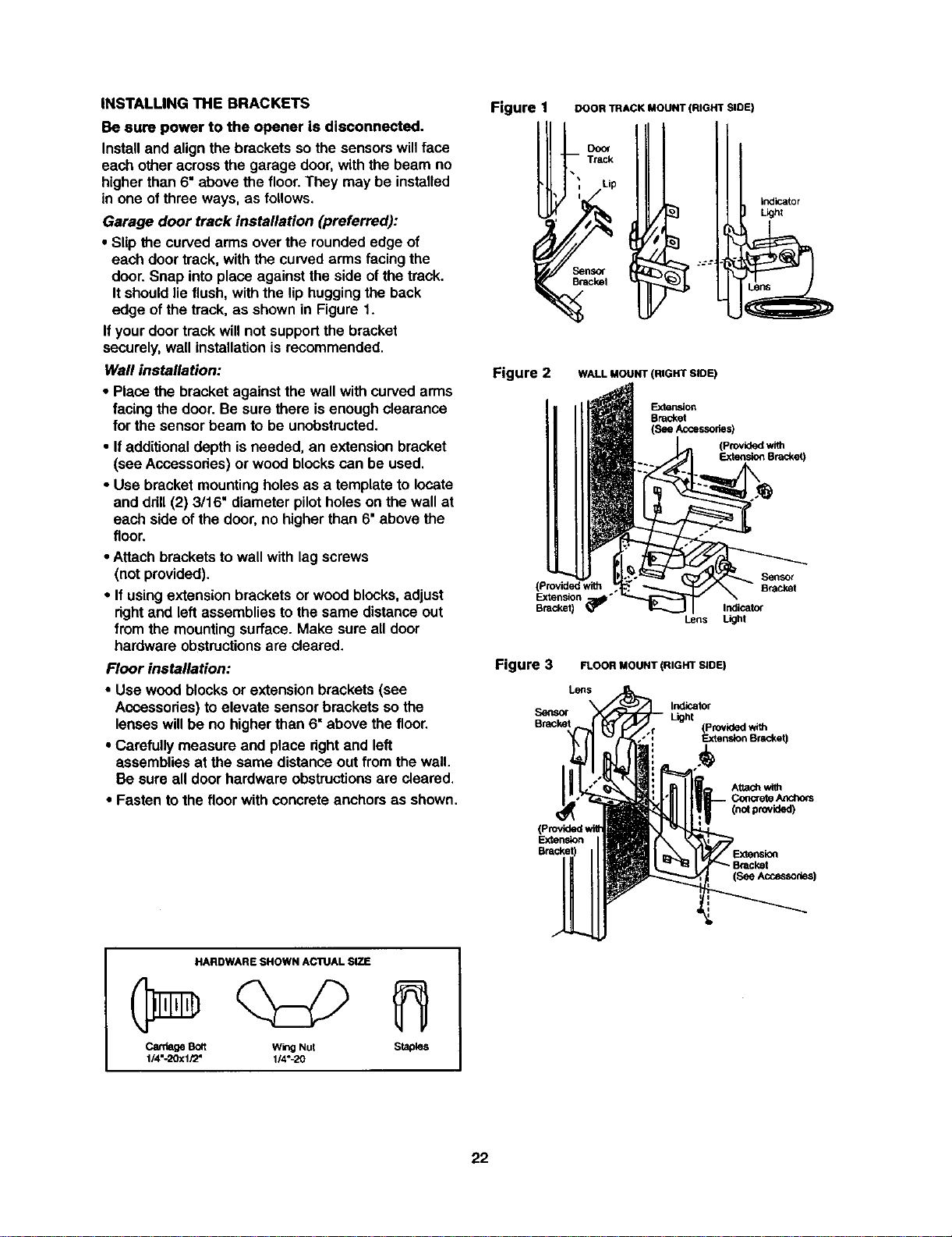
INSTALLINGTHEBRACKETS
Besurepowertotheopenerisdisconnected.
Installandalignthebracketssothe sensorswillface
each other acrossthe garage door,with the beam no
higherthan 6" above the floor.They may be installed
in one ofthree ways, as follows.
Garage door track installation (preferred):
• Slip the curvedarms overthe rounded edge of
each door track, with the curvedarms facingthe
door.Snap into place against the side ofthe track.
Itshouldlie flush,with the liphuggingthe back
edge ofthe track, as shownin Figure 1.
Ifyour door trackwillnot supportthe bracket
securely, wall installationis recommended.
Wall installation:
• Place the bracket againstthe wall withcurved arms
facingthe door. Be sure there isenough clearance
for the sensorbeam to be unobstructed.
• Ifadditionaldepth isneeded, an extension bracket
(see Accessodes)or woodblockscan be used.
• Use bracket mountingholes as a template to locate
and ddll (2) 3/16" diameter pilotholes on the wall at
each side of the door,no higherthan 6" above the
floor.
• Attach brackets to wall with lag screws
(not provided).
• If usingextension brackets or wood blocks,adjust
rightand left assembliesto the same distanceout
from the mountingsurface. Make sure all door
hardware obstructionsare cleared.
Floor installation:
• Use wood blocksor extension brackets (see
Accessories) toelevate sensor bracketsso the
lenses willbe no higherthan 6" above the floor,
• Carefully measure and place dghtand left
assembliesat the same distance out fromthe wall.
Be sure all door hardware obstructionsare cleared.
• Fasten to the floorwith concreteanchors as shown.
Figure 1
DOOR TRACK MOUNT (RIGHT SIDE)
, Track
Lip
_n_
Bme_l
indicator
Llghl
Figure 2 WALL MOUNT (RIGHT SLOE)
Exte_on
Bracket
(See Accessories)
d with
Bracket)
(Provided with
Extension '
Bracket)
Lens
Figure 3 FLOOR MOUNT (RIGHT SLOE)
Logs
Senso_
Bracket
Indicator
Light
(Providedwith
Extem_on Bracket)
(no_provided)
Extension
(SeeAccesso_s)
HARDWARE SHOWN AC1UAL SIZE
CardageBolt wingNut Staples
1/4"-20xl/2" 1/4"-20
22
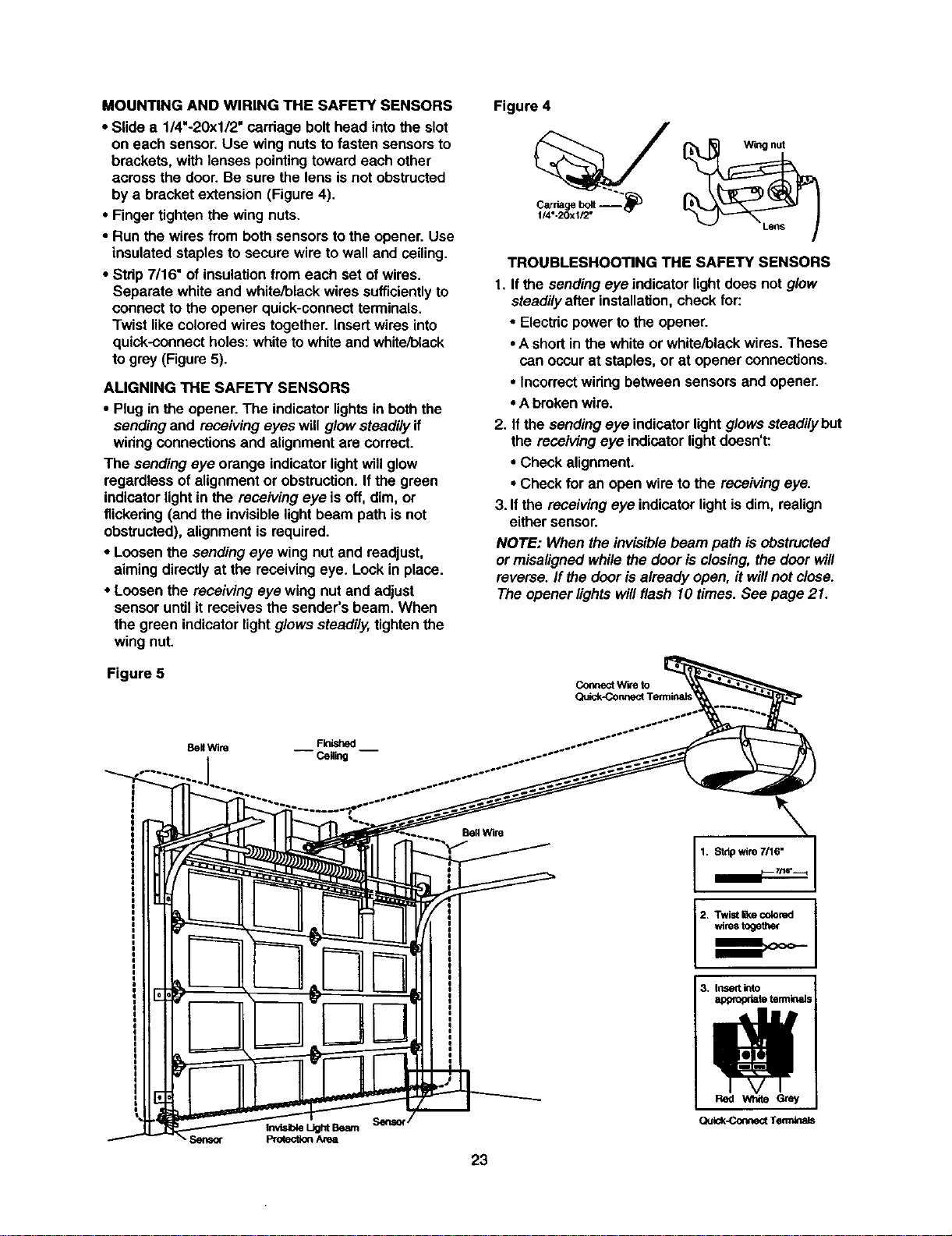
MOUNTINGANDWIRINGTHESAFETYSENSORS
• Slide a 114"-20x112"carriage bolthead intothe slot
on each sensor, Use wing nuts to fasten sensorsto
brackets, with lenses pointingtoward each other
across the door.Be sure the lens isnot obstructed
bya bracket extension (Figure 4).
• Fingertighten the wing nuts.
• Run the wires from both sensorstothe opener. Use
insulatedstaplesto secure wire to wall and ceiling.
• Strip7/16" of insulationfrom each set of wires.
Separate white and white/blackwires sufficientlyto
connectto the opener quick-connectterminals.
Twist like coloredwires together. Insertwires into
quick-connectholes:whiteto whiteand white/black
togrey (Figure5).
AUGNING THE SAFETY SENSORS
• Plugin the opener. The indicator lightsin boththe
sendingand receivingeyes will glowsteadilyif
winng connectionsand alignmentare correct.
The sendingeye orange indicatorlightwillglow
regardless ofalignmentor obstruction.If the green
indicatorlight in the receiving eye is off, dim, or
flickering (and the invisiblelightbeam path is not
obstructed),alignment is required.
• Loosenthe sendingeye wing nut and readjust,
aimingdirectly at the receivingeye. Lock in place.
• Loosen the receiving eye wing nut and adjust
sensoruntil it receives the sender's beam. When
the green indicatorlight glowssteadily,tightenthe
wingnut.
Figure 5
Figure 4
Carnagebolt "_"
1/4"-20xl/2"
TROUBLESHOOTING THE SAFETY SENSORS
1. If the sendingeye indicatorlightdoes not glow
steadilyafter installation,check for:
• Electdcpower to the opener.
•A shortin the white or white/blackwires.These
can occurat staples,or at opener connections.
• Incorrectwiringbetween sensorsand opener.
• Abrokenwire.
2. Ifthe sendingeye indicatorlight glowssteadilybut
the receivingeye indicatorlightdoesn't:
• Check alignment.
• Check for an open wire to the receivingeye.
3. Ifthe receivingeye indicatorlightis dim, realign
either sensor.
NOTE: When the invisiblebeam path isobstructed
or misalignedwhilethe door is closing,the door will
reverse.If the dooris already open, it willnot close.
The opener lightswillflash 10 times. See page 21.
Coflnect w'we to
BellWire Finished
-- Ceg_g --
1. Stdp wire 7n6"
2+ Twist _e colored
wirestogether
23
3. Inset into
appropriate terminals
Quk:k-ConnectTerrrdna_
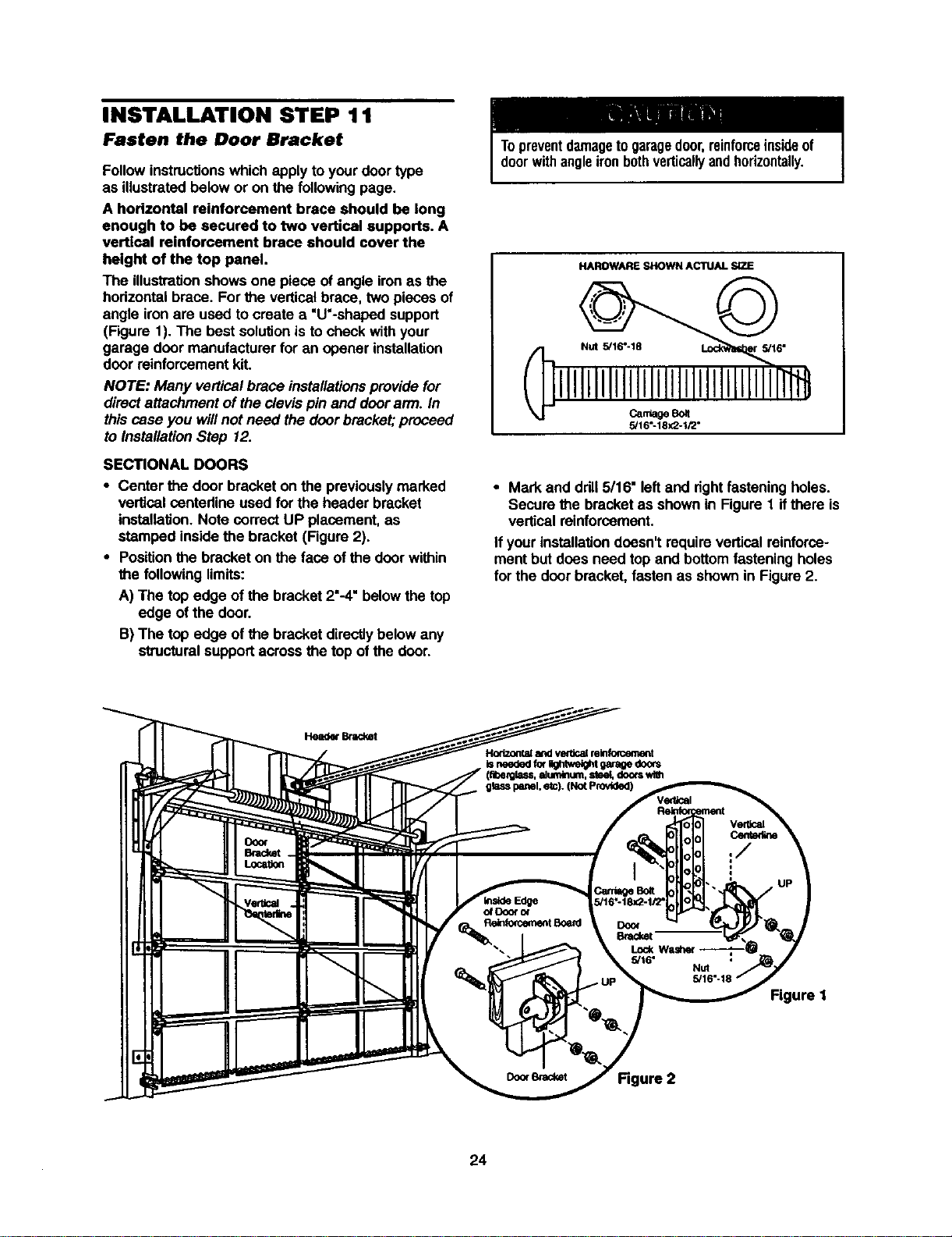
INSTALLATION STEP 11
Fasten the Door Bracket
Follow instructionswhich applyto yourdoor type
as illustratedbelow or on the following page.
A horizontal reinforcement brace should be long
enough to be secured to two vertical supports. A
vertical reinforcement brace should cover the
height of the top panel.
The illustrationshowsone piece of angle ironas the
hodzontal brace. Forthe verticalbrace, two pieces of
angle ironare used to create a "U'-shaped support
(Figure 1). The best solutionisto checkwith your
garage door manufacturerfor an opener installation
door reinforcementkit.
NOTE: Many verticalbrace installationsprovide for
directattachment of theclevis pin and door ann. In
this case you willnot need the doorbracket;proceed
to InstallationStep 12.
SECTIONAL DOORS
• Center the door bracket on the previouslymarked
vertical centedine used for the header bracket
installation.Note correctUP placement, as
stamped insidethe bracket (Figure 2).
• Positionthe bracket on the face of the door within
the followinglimits:
A) The top edge of the bracket 2"-4"belowthe top
edge of the door.
B) The top edge of the bracket directlybelow any
structuralsupportacross the top of the door.
Topreventdamageto garagedoor,reinforceinsideof
doorwithangleironbothverticallyandhorizontally.
HAROWARE SHOWN ACTUAL SIZE
CantleSot
5/16"-18X2-1/2"
• Mark and ddll 5/16" leftand rightfasteningholes.
Secure the bracketas shownin Figure 1 ifthere is
verticalreinforcement.
If yourinstallationdoesn'trequire verticalreinforce-
mentbut does need top and bottomfasteningholes
for the doerbracket, fastenas shown in Figure2.
Head_ Bnv:ket
Hodzontala_l vetticalminfomement
Isneededfo(_*e_ht gaffe doors
doorswlm
Figure I
24
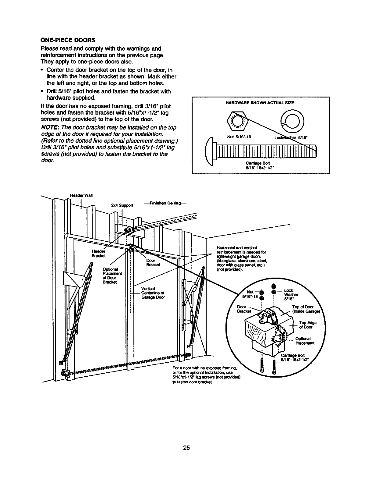
ONE-PIECEDOORS
Pleasereadandcomplywiththewarningsand
reinforcementinstructionsonthe previouspage.
They applyto one-piece doors also.
• Center the door bracket on the top ofthe door, in
linewith the header bracket as shown. Mark either
the left and right,or the top and bottomholes.
• Ddll 5/16" pilotholes and fasten the bracket with
hardware supplied.
If the door has no exposedframing, drill3/16" pilot
holesand fasten the bracket with 5/16"xl -1,"2"lag
screws (notprovided) tothe top ofthe door.
NOTE: The door bracketmay be installedon the top
edge of the door ifrequired for your installation.
(Refer to thedotted lineoptionalplacement drawing.)
Drill3/16" pilot holes and substitute5/16"x1-1/2" lag
screws (notprovided) tofasten the bracket to the
door.
HARDWARE SHOWN ACTUAL SiZE
CantageBolt
5/16"-18x2-tPZ'
He_ Wall
2:<4Support
Horizontal and vertical
relnfo_ement isneeded for
_tv,eight 0aragedocxs
(lit_ rglass,81um_um, steel,
doorwithglasspanel,etc.)
(notwovtde_.
FOra door with no exposed 1taming.
or for Ihe opUonalinstalla6on, use
5/16"xl -1/2" lag screws (not provided)
to fasten door brackeL
25
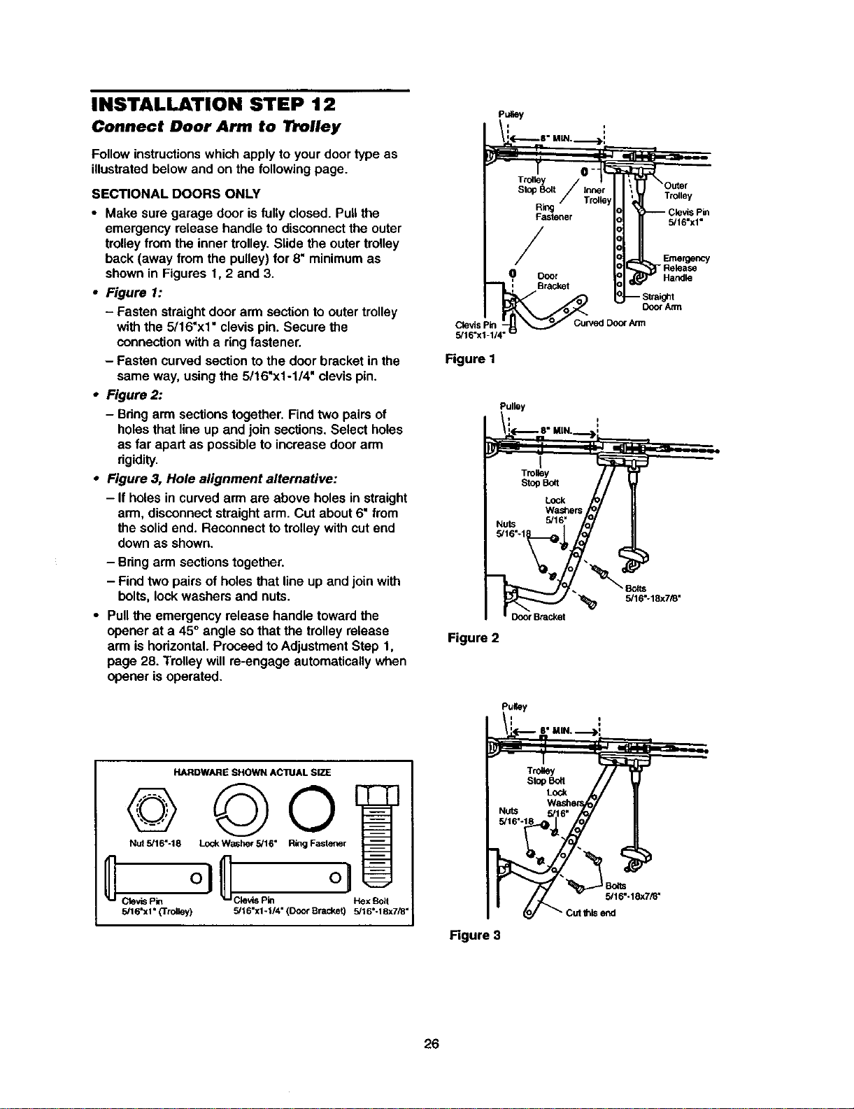
INSTALLATION STEP 12
P.,ey
Connect Door Arm to Trolley
Followinstructionswhichapply to yourdoor type as
illustratedbelowand on the following page.
SECTIONAL DOORS ONLY
• Make sure garage door isfullyclosed. Pull the
emergency release handle to disconnectthe outer
trolleyfrom the inner trolley.Slide the outertrolley
back (away from the pulley) for 8" minimumas
shownin Figures 1, 2 and 3.
• Figure 1:
- Fasten straightdoor arm sectionto outertrolley
withthe 5/16"xl" clevis pin. Secure the
connectionwith a ringfastener.
- Fasten curvedsectionto the doorbracket in the
same way, usingthe 5/16"x1-1/4" clevis pin.
• Figure 2:
- Bringarmsectionstogether. Find two pairsof
holesthat lineup and join sections. Select holes
as far apart as possibleto increase doorarm
rigidity.
• Figure 3, Hole alignment alternative:
- If holes in curvedarm are above holes in straight
arm, disconnectstraightarm. Cut about6" from
the solidend. Reconnect to trolleywith cutend
down as shown.
- Bringarm sectionstogether.
- Find two pairs of holes that lineup and join with
bolts, lock washers and nuts.
• Pull the emergency release handle towardthe
opener at a 45° angle sothat the trolley release
arm ishorizontal.Proceed toAdjustmentStep 1,
page 28. Trolleywill re-engage automaticallywhen
opener isoperated.
HARDWARE SHOWN ACTUAL SIZE
Nut 5/16"-18 Lock Washer 5/16" Ring Fastener
5/16'xl" {'Trolley) 5/16"xl -I/4" (Door Bracket) 5/16"-18x7/8"
Trolley
5/16"x1"
Clevis pin
5/16"x1-1/4'
Figure I
Emergency
- Release
Handle
Door Atrn
Cuwed Door Ann
Pulley
/L(-.-.--_ 8" MIN.__])'
- n
j
I
Trolley
s_ _
W_
Nuts 5/16" fo_
_Bolts
5/16_18x7_"
Figure 2
i_'i_ 8" MIN, "_>i
__ rf _,- _ _ _
Figure 3
26
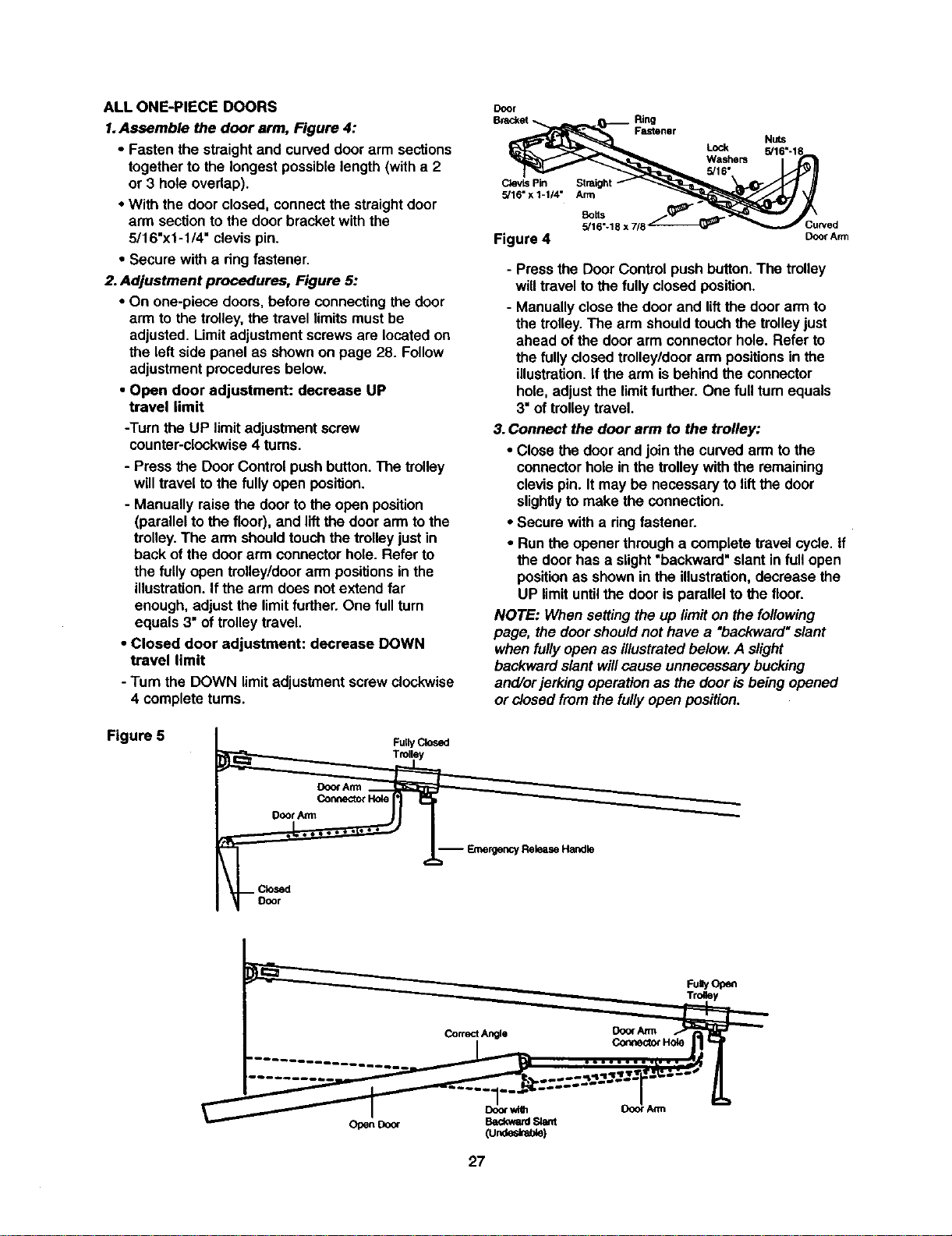
ALLONE-PIECEDOORS
1.Assemble the door arm, Figure 4:
• Fasten the straight and curved door arm sections
together to the longest possible length (with a 2
or 3 hole overlap).
• With the door closed, connect the straight door
arm section to the door bracket with the
5/16"x1-1/4" clevis pin.
• Secure with a dng fastener.
2. Adjustment procedures, Figure 5:
• On one-piece doors, before connecting the door
arm to the trolley, the travel limits must be
adjusted. Limit adjustment screws are located on
the left side panel as shown on page 28. Follow
adjustment procedures below.
• Open door adjustment: decrease UP
travel limit
-Turn the UP limitadjustmentscrew
counter-clockwise4 turns.
- Pressthe Door Control pushbutton.The trolley
willtravel tothe fullyopen position.
- Manually raise the door tothe open position
(parallelto the floor), and liftthe door arm to the
trolley.The arm shouldtouchthe trolleyjust in
back ofthe door arm connectorhole. Refer to
the fully open trolley/doorarm positionsinthe
illustration.Ifthe arm does not extend far
enough, adjustthe limitfurther. One full turn
equals 3"of trolleytravel.
• Closed door adjustment: decrease DOWN
travel limit
- Turn the DOWN limitadjustment screwclockwise
4 complete turns.
Door
Ring
Fastener
CtevLsPin
5/16" x 1-1/4" Arm
Lock
Washers
5/16"
Nuts
5/16"-1_
Botts
5/16"-18 x 7/8 Curved
Figure 4 DoorArm
- Pressthe Door Control pushbutton.The trolley
willtravel to the fully closedposition.
- Manuallyclose thedoor and liftthe door arm to
the trolley.The arm shouldtouchthe trolleyjust
ahead of the door arm connectorhole. Refer to
the fully closedtrolley/doorarm positionsin the
illustration.If the arm is behindthe connector
hole, adjustthe limitfurther. One full turnequals
3"of trolleytravel.
3.Connect the door arm to the trolley:
• Close the door and join the curvedarm to the
connectorhole in the trolleywith the remaining
clevispin. Itmay be necessaryto lift the door
slightlyto make the connection.
• Secure with a ringfastener.
• Runthe opener through a completetravel cycle. If
the door has a slight"backward"slant in full open
positionas shownin the illustration,decrease the
UP limituntilthe door isparallel tothe floor.
NOTE: When settingthe up limiton the following
page, the doorshouldnot have a "backward"slant
when fullyopen as illustratedbelow.A slight
backwardslant will cause unnecessary bucking
and/orjerkingoperation as the door isbeing opened
or closedfrom the futiyopen position.
Figure 5
FullyClosed
Trolley
Door An'n
Connector Hole
-- EmergencyReleaseHandle
FuayOp_
27
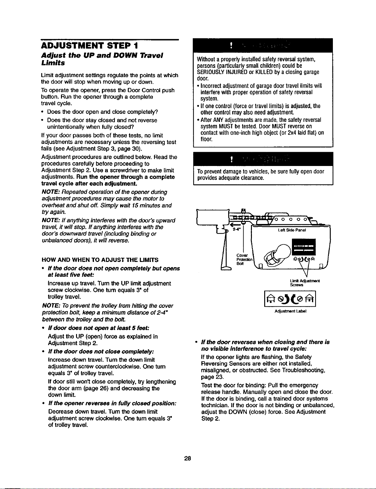
ADJUSTMENT STEP 1
Adjust the UP and DOWN lr_avel
Limits
Limitadjustmentsettingsregulatethe points at which
the door willstop when movingup or down.
To operate the opener, press the Door Controlpush
button. Runthe opener through a complete
travel cycle.
• Does the door open and close completely?
• Does the doer stay closed and not reverse
unintentionallywhen fully closed?
If yourdoor passes bothof these tests,no limit
adjustmentsare necessary unlessthe reversingtest
fails (sea AdjustmentStep 3, page 30).
Adjustmentproceduresare outlinedbelow. Read the
procedures carefullybefore proceedingto
AdjustmentStep 2. Use a screwdriverto make limit
adjustments.Run the opener through a complete
travel cycle after each adjustment.
NOTE: Repeated operationof the opener dudng
adjustmentprocedures may cause themotorto
overheat and shutoff. Simplywa# 15 minutesand
tryagain.
NOTE: If anythinginterferes with the door'supward
travel,it willstop. ff anythinginterfereswith the
door'sdownward travel (includingbindingor
unbalanceddoors), it will reverse.
HOW AND WHEN TO ADJUST THE UMrFS
• If the door does not open completely but opens
at least five feet:
Increase up travel. Tum the UP limitadjustment
screwclockwise. One turn equals3" of
trolleytravel.
NOTE: Toprevent the trolleyfromhittingthecover
protectionbolt, keep a minimumdistanceof2-4"
between the trolleyand the bolt.
• If door does not open at least 5 feet:
Adjustthe UP (open) forceas explainedin
AdjustmentStep 2.
• If the door does not close completely:
Increase downtravel. Turnthe downlimit
adjustmentscrewcountemlockwise.One tum
equals3" of trolleytravel.
If door stillwon't close completely,try lengthening
the door arm (page 26) and decreasingthe
downlimit.
• If the opener reverses in fully closed position:
Decrease down travel.Turn the down limit
adjustmentscrew clockwise,One turnequals 3"
oftrolley travel.
Withouta properlyinstalledsafetyreversalsystem,
persons(particularlysmallchildren)couldbe
SERIOUSLYINJUREDor KILLEDbya closinggarage
door.
• Incorrectadjustmentofgaragedoortravellimitswill
interferewithproperoperationofsafetyreversal
system.
• Ifonecontrol(forceortravellimits)isadjusted,the
othercontrolmayalsoneedadjustment.
•AfterANYadjustmentsaremade,thesafetyreversal
systemMUSTbetested.DoorMUSTreverseon
contactwithone-inchhighobject(or 2x4laidflat)on
floor.
Topreventdamagetovehicles,besurefullyopendoor
providesadequateclearance.
Im
Covet
PIO_eC_O_
Bolt
• If the door reverses when closing and there is
no visible interference to travel cycle:
If the opener lightsare flashing, the Safety
Reversing Sensorsare either not installed,
misaligned,or obstructed.See Troubleshooting,
page 23.
Testthe door for binding:Pullthe emergency
release handle. Manually open and closethe door.
Ifthe dooris binding,cell a trained doer systems
technician. If the door isnot bindingor unbalanced,
adjustthe DOWN (close) force. See Adjustment
Step 2,
28
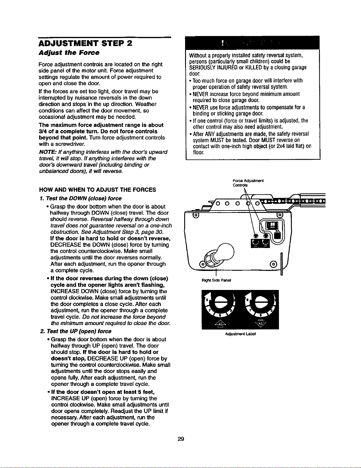
ADJUSTMENT STEP 2
Adjust the Force
Force adjustmentcontrolsare locatedon the right
side panel of the motorunit. Force adjustment
settingsregulatethe amountof power requiredto
open and closethe door.
If the forces are set too light,door travel may be
interruptedby nuisance reversalsin the down
directionand stops in the up direction,Weather
conditionscan affectthe doormovement, so
occasionaladjustmentmay be needed,
The maximum force adjustment range is about
3/4 of a complete turn. Do not force controls
beyond that point. Turn force adjustmentcontrols
with a screwdriver.
NOTE: ff anythinginterfereswith thedoor's upward
travel, ff willstop. Ifanythinginterferes withthe
door's downwardtravel (includingbindingor
unbalanced doors),it willreverse.
HOW AND WHEN TO ADJUST THE FORCES
1. Test the DOWN (close) force
• Grasp the door bottomwhen the door isabout
halfway throughDOWN (close) travel.The door
shouldreverse. Reversal halfway through down
travel does not guarantee reversalon a one-inch
obstruction.See AdjustmentStep 3, page 30.
If the door is hard to hold or doesn't reverse,
DECREASE the DOWN (close)force by turning
the controlcounterclockwise.Make small
adjustmentsuntilthe door reverses normally.
After each adjustment,runthe opener through
a complete cycle.
• If the door reverses during the down (close)
cycle end the opener lights aren't flashing,
INCREASE DOWN (close) force by turningthe
controlclock'wise.Make smalladjustmentsuntil
the door completesa closecycle. After each
adjustment,runthe opener through a complete
travel cycle. Do notincrease the force beyond
the minimumamountrequired to close the door.
2. Test the UP (open) force
• Grasp the door bottom when the door is about
halfwaythrough UP (open)travel. The door
shouldstop.If the door is hard to hold or
doesn't stop, DECREASE UP (open) force by
turningthe controlcounterclockwise. Make small
adjustmentsuntilthe door stops easily and
opens fully. After each adjustment,run the
opener through a completetravel cycle.
• If the door doesn't open at least 5 feet,
INCREASE UP (open)force by tuming the
controlclockwise. Make small adjustments until
door opens completely. Readjust the UP limitif
necessary.After each adjustment, runthe
opener through a complete travel cycle.
Withouta properlyinstalledsafetyreversalsystem,
persons(particularlysmallchildren)couldbe
SERIOUSLYINJUREDor KILLEDbya closinggarage
door.
• Toomuchforceongaragedoorwillinterferewith
properoperationof safetyreversalsystem.
• NEVERincreaseforce beyondminimumamount
requiredtoclosegaragedoor.
• NEVERuseforceadjustmentstocompensatefor a
bindingorstickinggaragedoor.
• If onecontrol(forceor travellimits)isadjusted,the
othercontrolmayalsoneedadjustment.
• AfterANYadjustmentsaremade,thesafetyreversal
systemMUSTbetested.DoorMUSTreverseon
contactwithone-inchhighobject(or 2x4laidflat)on
floor,
Force Adjusknent
Co_tr_s
O O
Right Side Panel
29
Adjus_nent Label
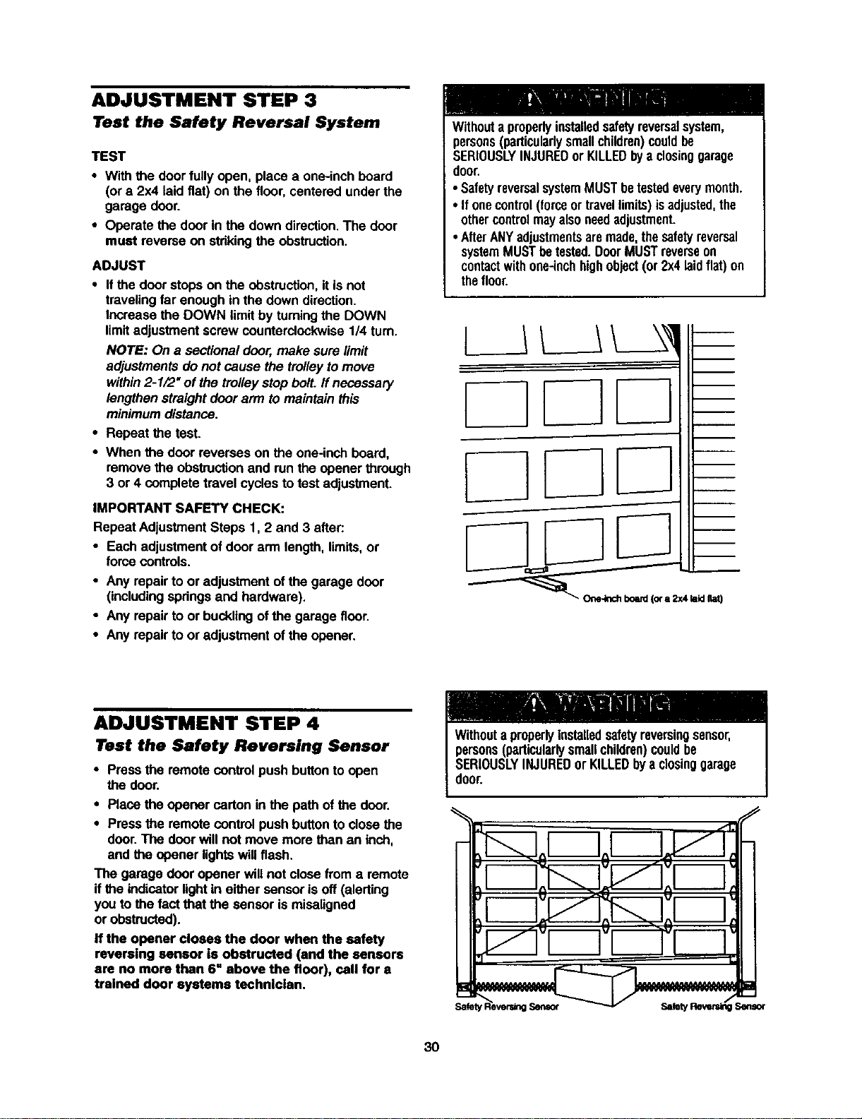
ADJUSTMENT STEP 3
Test the Safety Reversal System
TEST
• With the doorfully open, place a one-inchboard
(or a 2x4 laidfiat) on the floor, centeredunder the
garage door.
• Operate the door in the downdirection.The door
must reverse on stdkingthe obstruction.
ADJUST
• Ifthe door stops on the obstruction,itis not
travelingfar enough in the down direction.
Increase the DOWN limitby turningthe DOWN
limitadjustmentscrew counterclockwise1/4 turn.
NOTE: On a sectional door,make sure limit
adjustments do not cause the trolleytomove
within2-1/2" of the trolleystop bolt. If necessary
lengthenstraightdoor arm tomaintain this
minimumdistance.
• Repeat the test.
• When the door reverses on the one-inch board,
remove the obstructionand runthe opener through
3 or 4 complete travel cyclesto test adjustment.
IMPORTANT SAFETY CHECK:
Repeat AdjustmentSteps 1, 2 and 3 after.-
• Each adjustment ofdoor arm length,limits,or
force controls.
• Any repair to or adjustment of the garage door
(includingspdngs and hardware).
• Any repairto or bucklingof the garage floor.
• Any repair to or adjustment of the opener.
Withouta properlyinstalledsafetyreversalsystem,
persons(particularlysmallchildren)couldbe
SERIOUSLYINJUREDor KILLEDbya closinggarage
door.
• SafetyreversalsystemMUSTbetestedeverymonth.
• If onecontrol(forceortravellimits)isadjusted,the
othercontrolmayalsoneedadjustment.
• AfterANYadjustmentsaremade,thesafetyreversal
systemMUSTbetested.DoorMUSTreverseon
contactwithone-inchhighobject(or 2x4laidflat) on
thefloor.
ADJUSTMENT STEP 4
Test the Safety Reversing Sensor
• Pressthe remote controlpush buttonto open
the door.
• Place the opener carton inthe path of the door.
• Pressthe remote controlpush buttonto close the
door.The doorwill not move more than an inch,
and the opener lightswillflash.
The garage door opener will not close from a remote
if the indicatorlightin either sensor isoff (alerting
you to the fact that the sensor is misaligned
or obstructed).
If the opener closes the door when the safety
reversing sensor is obstructed (and the sensors
are no more than 6" above the floor), call for a
trained door systems technician.
persons(particularlysmallchildren)couldbe
SERIOUSLYINJUREDorKILLEDbya dosinggarage
door.
o Io[ IJ _J,Ih
3O
OPERATION
IMPORTANT SAFETY INSTRUCTIONS
To reduce the risk of severe injury or death:
1. READANDFOLLOWALLWARNINGSAND
INSTRUCTIONS.
2. ALWAYSkeepremotecontrolsoutofreachofchildren.
NEVERpermitchildrentooperateor playwithgarage
doorcontrolpushbuttonsor remotecontrols.
3. ONLYactivategaragedoorwhenitcanbeseenclearly,it
isproperlyadjusted,andtherearenoobstructionsto
doortravel.
4. ALWAYSkeepgaragedoorin sightuntilcompletely
closed.NOONESHOULDCROSSTHEPATHOFTHE
MOVINGDOOR.
5. Ifpossible,useemergencyreleasehandleto disengage
trolleyONLYwhengaragedoorisCLOSED.Weakor
brokenspringsor unbalanceddoorcouldresultinan
opendoorfalling rapidlyand/orunexpectedly.
6. NEVERuseemergencyreleasehandleunlessgarage
doorwayisclearofpersonsandobstructions.
7. NEVERusehandleto pullgaragedooropenorclosed.If
ropeknotbecomesuntied,youcouldfall.
8. Ifonecontrol(forceortravellimits)isadjusted,the
othercontrolmayalsoneedadjustment.
9. Afteranyadjustmentsaremade,thesafetyreversal
systemMUSTbetested.
10.SafetyreversalsystemMUSTbe testedeverymonth.
GaragedoorMUSTreverseoncontactwithone-inch
highobject(ora 2x4 laidflat) onthefloor.
11.ALWAYSKEEPGARAGEDOORPROPERLYBALANCED
(seepage3). Animproperlybalanceddoormaynot
reversewhenrequiredandcouldresultin severeinjury
or death.
12.Allrepairstocables,springassembliesandother
hardware,allofwhichareunderEXTREMEtension,
MUSTbemadebya traineddoorsystemstechnician.
13.ALWAYSdisconnectelectricpowertogaragedoor
openerbeforemakinganyrepairsor removingcovers.
t4.SAVETHESEINSTRUCTIONS.
Using Your Garage Door Opener
YourSecurity.I.opener and hand-held remote control
have been factory-set to a matchingcode which
changeswith each use, randomlyaccessingover
100 billionnew codes. Youropener willoperate with
up to eight Security,l.remote controls and one
Secudty.l. Keyless Entry System. If you purchase a
new remote,or ifyou wish to deactivate any remote,
follow the instructionsin the Programmingsection.
Activate your opener with any of the following:
• The hand-held Remote Control:Hold the large
pushbutton downuntilthe door startsto move.
• The wall-mounted Door Control:Hold the push
buttondown untilthe door startsto move.
• TheKeylessEntry(SeeAcceasodea):lfprevided
with yourgarage door opener, it mustbe
programmed beforeuse. See Programming.
When the opener is activated (with the safety
reversing sensor correctly installed and aligned)
1. If open, the door willclose. If closed, itwillopen.
2. If closing,the door will reverse.
3. If opening, the door willstop.
4. If the door has been stopped in a partially open
position, it will close.
5. If obstructedwhiledosing, the door will reverse. If
the obstructioninterruptsthe sensorbeam, the
opener lightswillblinkfor fiveseconds.
6.If obstructedwhile opening,the door willstop.
7.If fully open, the door willnot close when the beam
is broken.The sensor has no effect in the opening
cycle.
If the sensoris not installed, or is misaligned,the
door won'tclose from a hand-held remote. However,
you can close the door with the Door Control,the
OutdoorKey Switch, or Keyless Entry,ifyou activate
them untildown travel is complete. If you release
them too soon, the door will reverse.
The opener lights willturn on underthe following
conditions: when the opener is initiallyplugged in;
when poweris restored after interruption;when the
opener isactivated.
They willturnoffautomaticallyafter 4-1_ minutesor
provideconstant lightwhen the Ught feature on the
MotionDetecting ControlConsole is activated.Bulb
size is 100 watts maximum.
Security,P Light Feature: Ughts willalso turnon
when someone walksthrough the open garage door.
With a MotionDetecting Control Console, thisfeature
may be turnedoff as follows:With the opener lights
off, press and hold the light buttonfor 10 seconds,
untilthe lightgoes on and offagain. To restorethis
feature, startwith the opener lightson, then press
and holdthe light buttonfor 10 secondsuntilthe light
goes off, then on again.
31
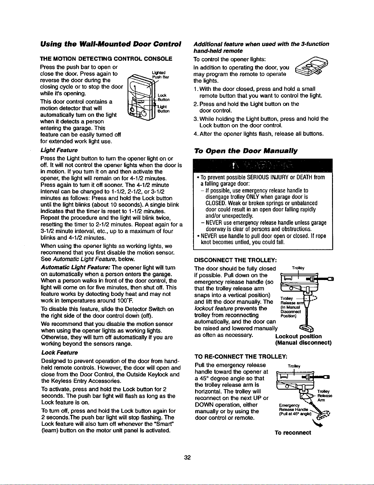
Using the Wall.Mounted Door Control
THE MOTION DETECTING CONTROL CONSOLE
Press the push bar to open or
close the door. Press again to
reverse the door during the
closingcycle or to stop the door
while it'sopening.
This door controlcontains a
motiondetectorthat will
automaticallyturn on the light
when itdetects a person
enteringthe garage. This
feature can be easily turned off
for extended work light use.
Light Feature
Lighted
Pressthe Ught button toturnthe opener lighton or
off. It willnot controlthe opener lightswhen the door is
in motion.If you turnit on and then activatethe
opener, the lightwill remain on for 4-1/2 minutes.
Pressagain toturn itoff sooner.The 4-1/2 minute
intervalcan be changed to 1-1/2, 2-112,or 3-112
minutesas follows: Pressand hold the Lock button
untilthe lightblinks (about 10 seconds).A singleblink
indicatesthat the timer is reset to 1-112minutes.
Repeat the procedure and the lightwillblinktwice,
resettingthe timer to 2-1/2 minutes.Repeat again for a
3-1/2 minuteinterval,etc., up to a maximumof four
blinksand 4-1/2 minutes.
When usingthe opener lightsas workinglights,we
recommend that youfirst disable the motionsensor.
See AutomaticLight Feature, below.
Automatic Light Feature: The opener lightwillturn
on automatically when a person entersthe garage.
When a person walks in front of the door control,the
lightwillcome on for five minutes,then shutoff. This
feature worksby detecting bodyheat and may not
work in temperatures around IO0"F.
To disable this feature, slidethe DetectorSwitch on
the dghtside of the door controldown (off).
We recommendthat you disable the motionsensor
when using the opener lightsas workinglights.
Otherwise, they willturn off automaticallyifyou are
workingbeyond the sensorsrange.
Lock Feature
Designed toprevent operation ofthe doorfrom hand-
held remote controls.However, the door willopen and
close from the Door Control, the OutsideKeylockand
the Keyless Entry Accessories.
To activate, press and hold the Lock buttonfor 2
seconds. The push bar lightwill flashas long as the
Lock feature ison.
To turnoff, press and hold the Lockbuttonagain for
2 seconds.The pushbar lightwillstop flashing. The
Lockfeature willalso turnoff wheneverthe =Smart"
(leam) button on the motorunitpanel isactivated.
Additional feature when used with the 3-function
hand-held remote
To controlthe opener lights:
In additionto operating the door,you
may program the remote to operate
the lights.
1.With the door closed, press and holda small
remote buttonthat you want to controlthe light.
2.Press and held the Light buttonon the
door control.
3.While holding the Lightbutton,press and hold the
Lockbutton on the door control.
4.After the opener lightsflash, release all buttons.
To Open the Door Manually
• TopreventpossibleSERIOUSINJURYor DEATHfrom
a falling garagedoor:
- If possible,useemergencyreleasehandleto
disengagetrolleyONLYwhengaragedooris
CLOSED.Weakor brokenspringsorunbalanced
doorcouldresultin anopendoorfallingrapidly
and/orunexpectedly.
- NEVERuseemergencyreleasehandleunlessgarage
doorwayisclearofpersonsandobstructions.
• NEVERusehandleto pulldooropenorclosed.If rope
knotbecomesuntied,youcouldfall.
DISCONNECT THE TROLLEY:
The door shouldbe fully closed
if possible.Pull down on the
emergency release handle (so
that the trolleyrelease arm
snaps intoa vertical position)
and liftthe door manually.The
lockout feature preventsthe
trolleyfrom reconnecting
automatically,and the door can
Trolley
_ I
Retease ann
(In Manual
DLsconnect
Posi_on)
be raised and lowered manually
as often as necessary. Lockout )osition
(Manual disconnect)
TO RE-CONNECT THE TROLLEY:
Pullthe emergency release
handle towardthe opener at
a 45° degree angle so that
the trolleyrelease arm is
horizontal.The trolley will
reconnecton the next UP or
DOWN operation,either
manually or byusing the
door control or remote.
Trolley
To reconnect
32
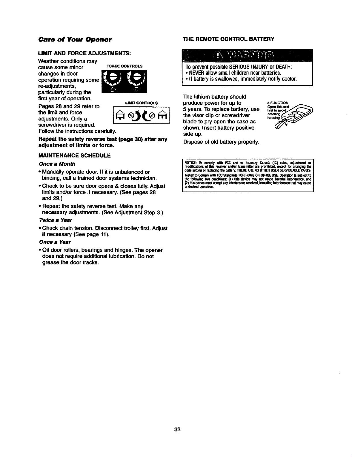
Care of Your Opener
UMIT AND FORCE ADJUSTMENTS:
Weather conditions may
cause some minor FORCECONTROLS
changes in door
operation requiringsome
re-adjustments,
particularlydudngthe
firstyear of operation.
uMrr CONTROLS
Pages 28 and 29 refer to
the limitand fome
adjustments. Only a
screwdriveris required.
Followthe instructionscarefully.
Repeat the safety reverse test (page 30) after any
adjustment of limits or force.
MAINTENANCE SCHEDULE
Once a Month
• Manually operate door.If it is unbalanced or
binding,call a trained door systems technician.
• Check to be sure door opens & closes fully.Adjust
limitsand/or force if necessary. (See pages 28
and 29.)
• Repeat the safety reverse test. Make any
necessary adjustments. (See AdjustmentStep 3.)
Twice a Year
• Check chaintension. Disconnecttrolley first. Adjust
if necessary (See page 11).
Once a Year
• Oil door rollers,beadngs and hinges.The opener
does not requireadditionallubdcafion.Do not
grease the door tracks.
THE REMOTE CONTROL BAI-rERY
The lithiumbattery should
producepower for up to
5 years. To replacebattery,use
the visor(dipor screwdriver
blade to pry open the case as
shown. Insertbatterypositive
side up.
Disposeof old battery properly.
3-FUNCTION
Openmlsend
NOTICE:TO complywith FCCand or Indue.,'./Canada(IC) ru_;, _ or
modlllcatiorlsof thiseeceivefand/orb'ansmitMrate _xohl_4ted,exceptIo_ckangin0the
codesegingor rep_ackqthebzge¢/.THERE_RENOOIHERLIS_ S_ PARTS.
Te:Stedto Contplywithrcc StandardsF0RHOME0R 0R:IC:EUSE_0perRioe_ subjectto
the_ W,Ocondition:(1) ridsdevicemaynotcsuseharmfulm, and
(2)thisde_cem_stacceptanyimderencereceive0,k_ inletfenmcethatmaycause
endesbedogeration.
33
Having a Problem?
1. The opener doesn't operate from either the Door
Control or the remote control:
• Does the opener have electricpower? Plug a lamp intothe
outlet. If it doesn't light, check the fuse box or the circuit
breaker, (Some outlets are controlledby a wall switch.)
• Have you disabled all door locks? Review installation
instructionwarnings on page 11.
• Is there a build-up of ice or snow under the door?The door
may be frozen to the ground. Remove any restriction.
• The garage door spring may be broken. Have it replaced,
• Repeated operationmay have tripped the overload
protector in the motor. Wait 15 minutesand try again,
2. Opener operates from the remote, but not from the
Door Control:
• Is the door controllit? If not, reverse the wires. If the
opener runs,check for a faulty wire connection at the door
control, a short under the staples, or a broken wire.
• Are the wiring connectionscorrect? Review Instal/atioo
Step 6, page 18,
3. The door operates from the Door Control, but not from
the remote control:
• Isthe door push button flashing?If yourmodel has the
Lockfeature, make sure it is off.
• Programthe opener to match the remote control code.
(Refer to instructionson the motorunit panel.) Repeat with
all remotes.
4. The remote control has short range:
• Change the locationof the remote controlin yourcar.
• Check to he sure the antenna on the side or back panel of
mater unit extends fully downward.
• Some installationsmay have shorter range due to a metal
dour,foil backed insulation, or metal garage siding.
(Antenna Extender Kit 41A3504)
5. Opener noise is disturbing in living quarters of home:
• If operational noise is a problem because of proximityof
the opener to the livingquarters, the Vibration IsolatorKit
41A3263 can be installed.This kit was designed to
minimize vibrationto the house and iseasy to install.
6. The garage door opens and closes by itself:
• Be sure that all remote cootrolpush buttonsare off.
• Remove the bell wire from the doorcontrol terminalsand
operate fromthe remote only. If this selves the problem,the
doorcnnt_ is faulty(replace),or thereis an intermittentshort
on the wirebetween the doorcontroland the motorunit.
• Clear memory and re-program all remotecontrols.
7. The door doesn't open completely:
• Issomething obstructingthe door? Is it out of balance, or
are the springsbroken? Remove the obstruction or repair
tha door.
• If the door is in good workingorder but now doesn't open
allthe way, increase the upforce. See AdjustmentStep 2.
• If the dooropens at least 5 font, the travel limitsmay need
to be increased. One turn equals 3 inches oftravel. See
AdjustmentStep 1.
Repeat the safety reverse test after the adjustment is
complete.
8. The door stops but doosn_ close completely:
• Review the travel limitsadjustment procedures on page 28,
Repeat the safety reverse test after any adjustmentof door
ann length, close force or down limit,
9. Tim door opens but won't close:
• If the opener lightsblink, check the safety reversing sensor.
See InstallationStep 10.
• Ifthe opener lightsdon'tblink and it isa new installation,
checkthe down force. See Adjustment Step 2. For an
existing installation,see below.
Repeat the safety reverse test aftertheadjustmentis c_vnplete.
10. The door reverses for no apparent reason and opener
lights don't blink:
• Issomethingobstructingthe door? Pullthe emergency
release handle.Operate the doormanually.If it is unbalanced
or binding,call a traineddoor systems technician.
• Clear any ice or snow fromthe garage floorarea where
the doorcloses.
• Review AdjustmentStep 2.
• If dourreverses in the fullyclosed position, decrease the
travel limits(AdjustmentStep 1).
Repeat safety reverse test after adjustments to forceor travel
limits. The need for occasional adjustmentof the force and
limitsettingsis normal Weather conditionsinparticular can
affect door travel.
11. The door reverses for no apparent reason and opener
lights blink for 5 seconds after reversing:
• Check the safety reversing sensor. Remove anyobstruction
or alignthe receivingeye, See InstallationStep 10.
12. 7he opener lights don't turn on:
• Replacethe lightbulbs(100 watts maximum).Use a standard
neck garage dooropenerbulbif regularbulbbumsout.
13. The opener lights don't turn off:
• Is the Lightfeature on?Turn it off.
14. The opener strains or maximum force is needed to
operate door:.
• The door may be outof balance or the springsmay be
broken. Close the door and usa the emergency release
handle to disconnectthe trolley.Open and close the door
manually.A properlybalanced door will stay in any point of
travel while being supportndentirelyby its springs. If it
does not, disconnectthe opener and calla trained door
systems technician.Do not Increase the force to operate
the opener.
15. The opener motor hums briefly, then won't work:
• The garage doorspdngs may he broken.Son above.
• If the problem occurson the firstoperationof the opener,
door may be locked. Disable the door lock. if the chain was
removed and reinstalled, the motormay be outof phase.
Remove the chain; cyclethe motor to the down po_;ition.
Observe the drive sprocket. When it turnsin a clockwise
directionand stops in the down position,reinstallthe chain,
Repeat the safety reverse test after the adjustmentis
complete.
16. The opener won't operate due to power failure:
• Use the emergency release handle to disconnectthe
troiisy.The door can be opened and closed manually.
When power is restored, press the DoorControl push
buttonand trolleywill automatically reconnect(unless
trolleyis in lockoutpotion.) See page 32.
• The Emergency Key Release accessory (for use on
garages with no service door) disconnectsthe trolleyfrom
outsidethe garage in case of powerfailure.
17. The chain droops or sags:
• It is nermai forthe chain to droopslightlyin the oioned door
position.Use the emergency release to disconnectthe
trolley, if the chain returnsto normal heightwhen the trolley
is disengaged and the door reverses on a ona-inch board,
no adjustments are needed (see page 11).
34
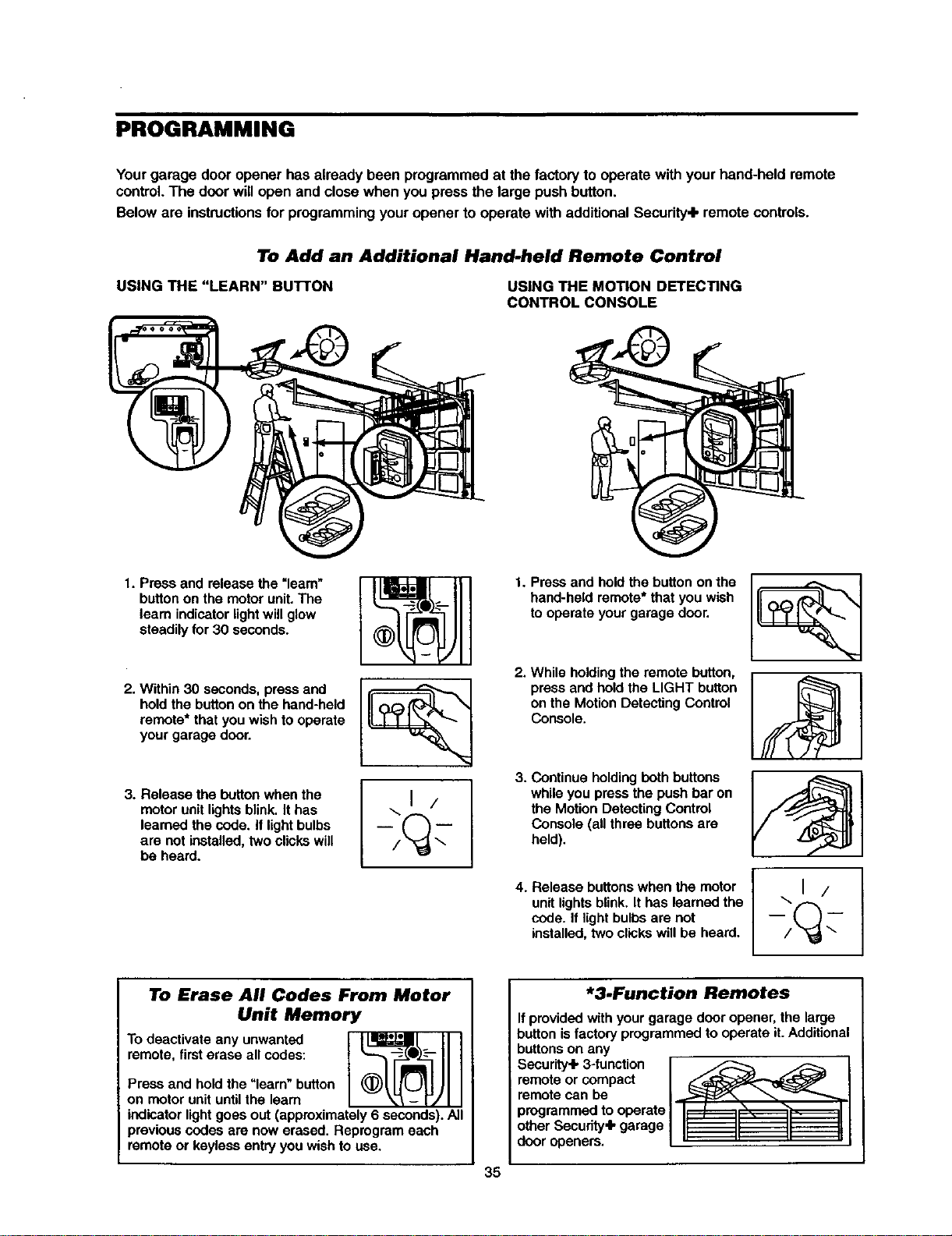
PROGRAMMING
Yourgarage door opener has already been programmed at the factory to operate withyour hand-held remote
control.The door willopen and closewhen you press the large pushbutton.
Below are instructionsfor programmingyouropener to operate withadditionalSecurity+ remote controls.
To Add an Additional Hand-held Remote Control
USING THE "LEARN" BUTrON USING THE MOTION DETECTING
CONTROL CONSOLE
1. Press and release the =learn"
button on the motor unit. The
learn indicator light will glow
steadily for 30 seconds.
2. Within 30 seconds, press and
hold the button on the hand-held
remote* that you wish to operate
your garage door.
3. Release the button when the
motor unit lights blink, It has
learned the code. it light bulbs
are not installed, two clicks will
be heard.
\1 /
1. Press and hold the button on the
hand-held remote* that you wish
to operate your garage door.
2. While holding the remote button,
press and hold the LIGHT button
on the Motion Detecting Control
Console.
3. Continue holding both buttons
while you press the push bar on
the Motion Detecting Control
Console (all three buttons are
held).
4. Release buttons when the motor
unit lights blink. It has learned the
code. If light bulbs are not
installed, two clicks will be heard.
To Erase All Codes From Motor
Unit Memory
To deactivate any unwanted
remote, first erase all codes:
Press and hold the "learn" button
on motor unit until the learn
indicator light goes out (approximately 6 seconds). All
previous codes are now erased. Reprogram each
remote or keyless entry you wish to use.
*3.Function Remotes
If provided with your garage door opener, the large
button is factory programmed to operate it. Additional
buttons on any
Security.lk3-function F _
remote or compact / _--/'_
remote can be /.,...._f_ _
programmedto operate/1L / ,D', ,I
other Secudty'lk garage / II II II I1
door openers. L" " " _
35
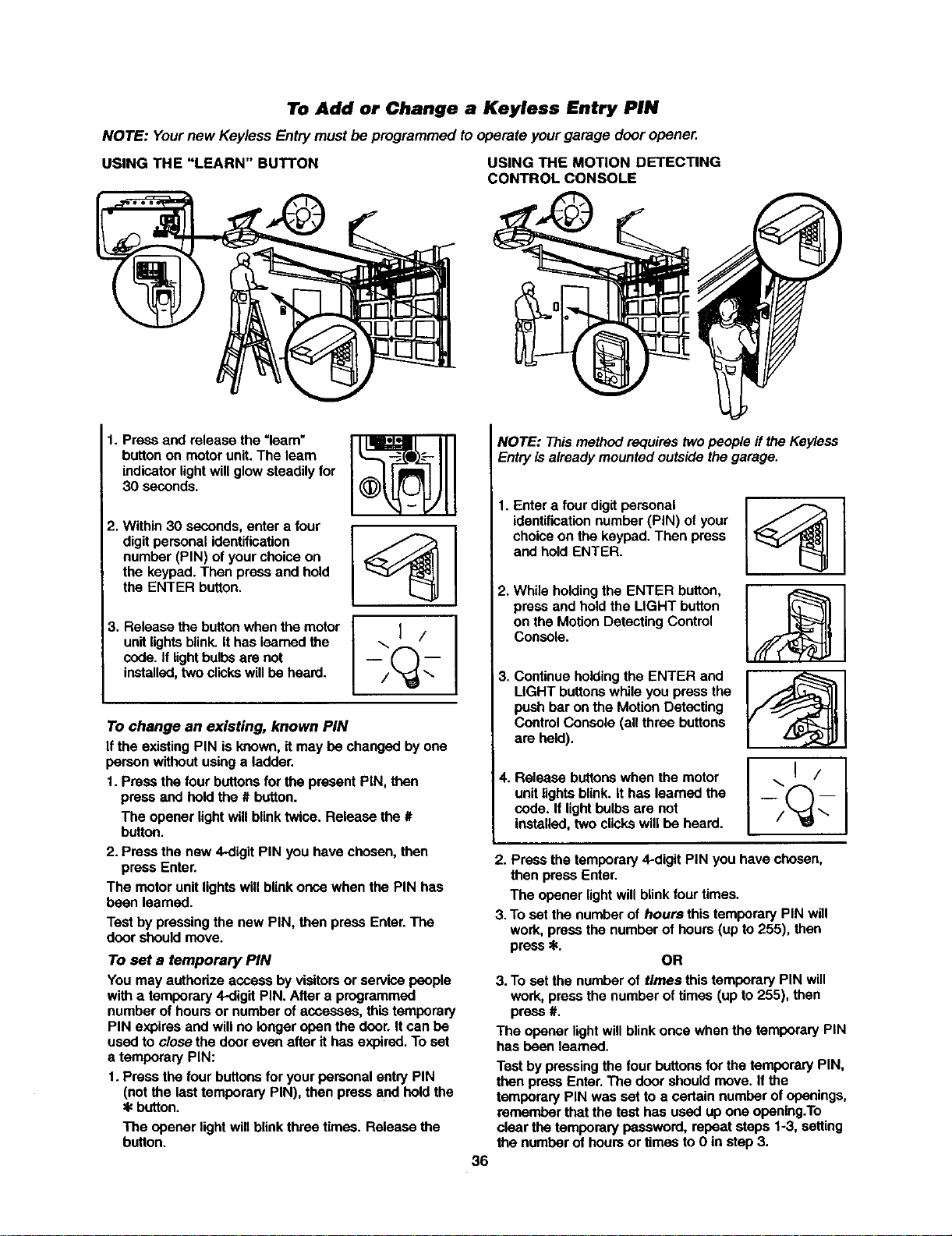
To Add or Change a Keyless Entry PIN
NOTE: Yournew Keyless Entry must beprogrammed to operateyourgarage door opener.
USING THE "LEARN" BUTTON USING THE MOTION DETECTING
CONTROL CONSOLE
1. Press and release the =learn"
button on motor unit. The learn
indicator light will glow steadily for
30 seconds.
2. Within 30 seconds, enter a four
digit personal identification
number (PIN) of your choice on
the keypad. Then press and hold
the ENTER button.
3. Release the button when the motor
unit lights blink. It has learned the
code. If lightbulbs are not
installed, two clicks will be heard.
...I/
To change an existing, known PIN
If the existing PIN is known, it may be changed by one
person without using a ladder.
1. Press the four buttons for the present PiN, then
press and hold the # button.
The opener light will blink twice. Release the #
button.
2. Press the new 4-digit PIN you have chosen, then
press Enter.
The motor unit lights will blink once when the PIN has
been learned.
Test by pressing the new PIN, then press Enter. The
door should move.
To set a temporary PIN
You may authorize access by visitors or service people
with a temporary 4-digit PIN. After a programmed
number of hours or number of accesses, this temporary
PIN expires and will no longer open the door. It can be
used to close the door even after it has expired. To set
a temporary PIN:
1. Press the four buttons for your personal entry PIN
(not the last temporary PIN), then press and hold the
button.
The opener light will blink three times. Release the
button.
NOTE: This method requires two people if the Keyless
Entry is already mounted outside the garage.
36
1. Enter a four digit personal
identification number (PIN) of your
choice on the keypad. Then press
and hold ENTER.
2. While holding the ENTER button,
press and hold the LIGHT button
on the Motion Detecting Control
Console.
3. Continue holding the ENTER and
LIGHT buttons while you press the
push bar on the Motion Detecting
Control Console (all three buttons
are held).
4. Release buttons when the motor
unit lights blink. It has learned the
code. If light bulbs are not
installed, two clicks will be heard.
\1 /
2. Press the temporary 4-digit PIN you have chosen,
then press Enter.
The opener light will blink four times.
3. To set the number of hours this temporary PIN will
work, press the number of hours (up to 255), then
press _.
OR
3. To set the number of times this temporary PIN will
work, press the number of times (up to 255), then
press #.
The opener light will blink once when the temporary PIN
has been learned.
Test by pressing the four buttons for the temporary PIN,
then press Enter. The door should move. If the
temporary PIN was set to a certain number of openings,
remember that the test has used up one opening.To
clear the temporary password, repeat stops 1-3, setting
the number of hours or times to 0 in step 3.
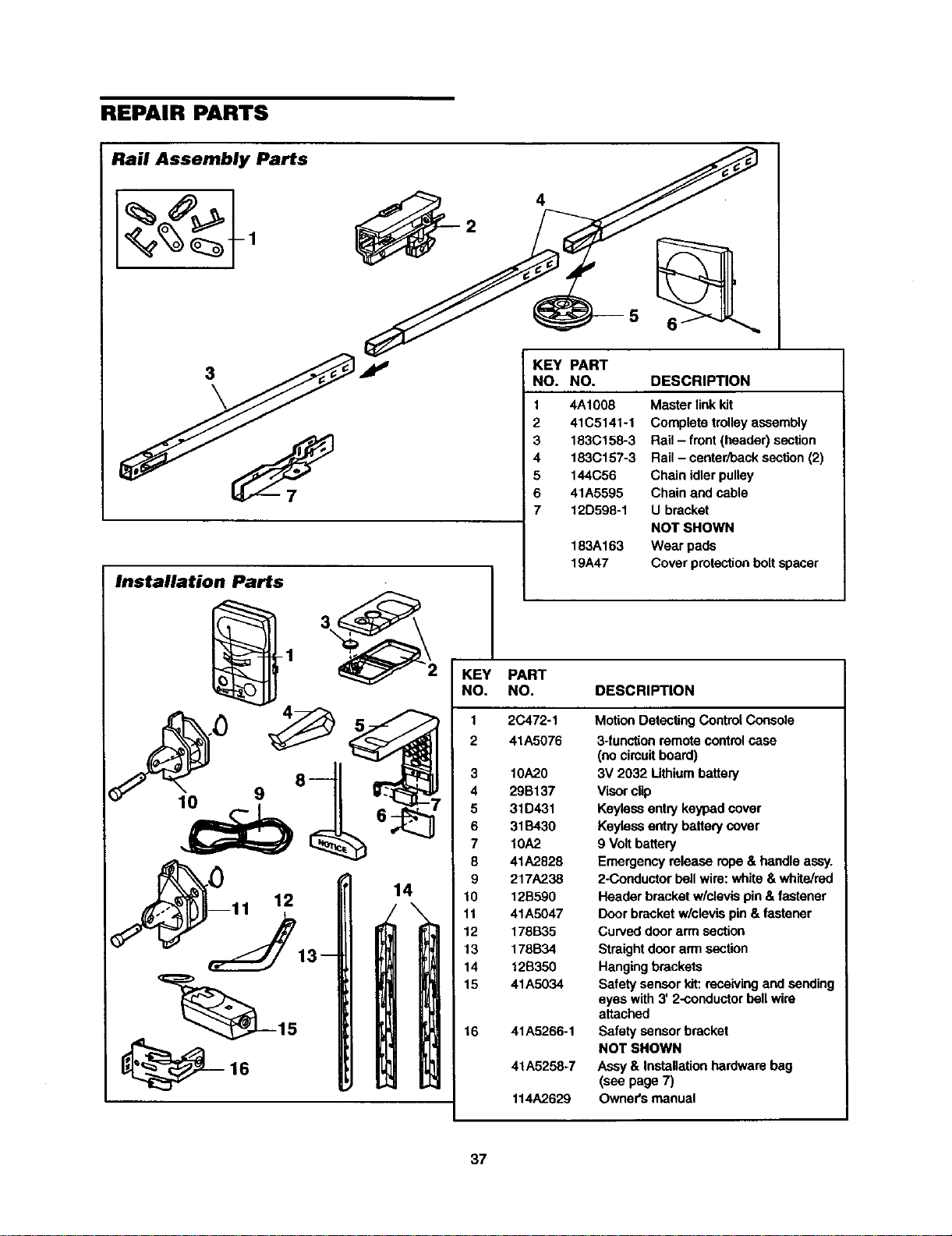
REPAIR PARTS
Rail Assembly Parts
4
5
3
Installation Parts
KEY PART
NO. NO. DESCRIPTION
1
2
3
4
5
6
7
1
KEY PART
NO. NO.
2 41A5076
_ 3 10A20
9 8 4 29B137
5 31D431
6 31B430
7 10A2
8 41A2828
__) 9 217A238
11 12 14 10 12B590
\ 11 41A5047
12 178B35
13 178B34
14 12B350
15 41A5034
15 16 41A5266-1
16 41A5258-7
114A2629
4A1008 Master linkkit
41C5141-1 Complete trolley assembly
183(3158-3 Rail - front(header) section
183C157-3 Rail - center/back section (2)
144C56 Chain idler pulley
41A5595 Chain and cable
12D598-1 U bracket
NOT SHOWN
183A163 Wear pads
19A47 Cover protectionboltspacer
DESCRIPTION
Motion Detecting Control Console
3-functionremotecontrolcase
(nocircuitboard)
3V 2032 Lithiumbattery
Visorclip
Keyless entry keypad cover
Keyiossentry battery cover
9 Volt battery
Emergency release rope & handle assy.
2-Conductor bellwire: white & white/red
Header bracketw/clevis pin& fastener
Door bracket w/clevis pin & fastener
Curved door arm section
Straight door arrnsection
Hangingbrackets
Safety sensorkit: receivingand sending
eyes with 3' 2-conductorbell wire
attached
Safety sensorbracket
NOT SHOWN
Assy & Installation hardware bag
(see page 7)
Owner's manual
37
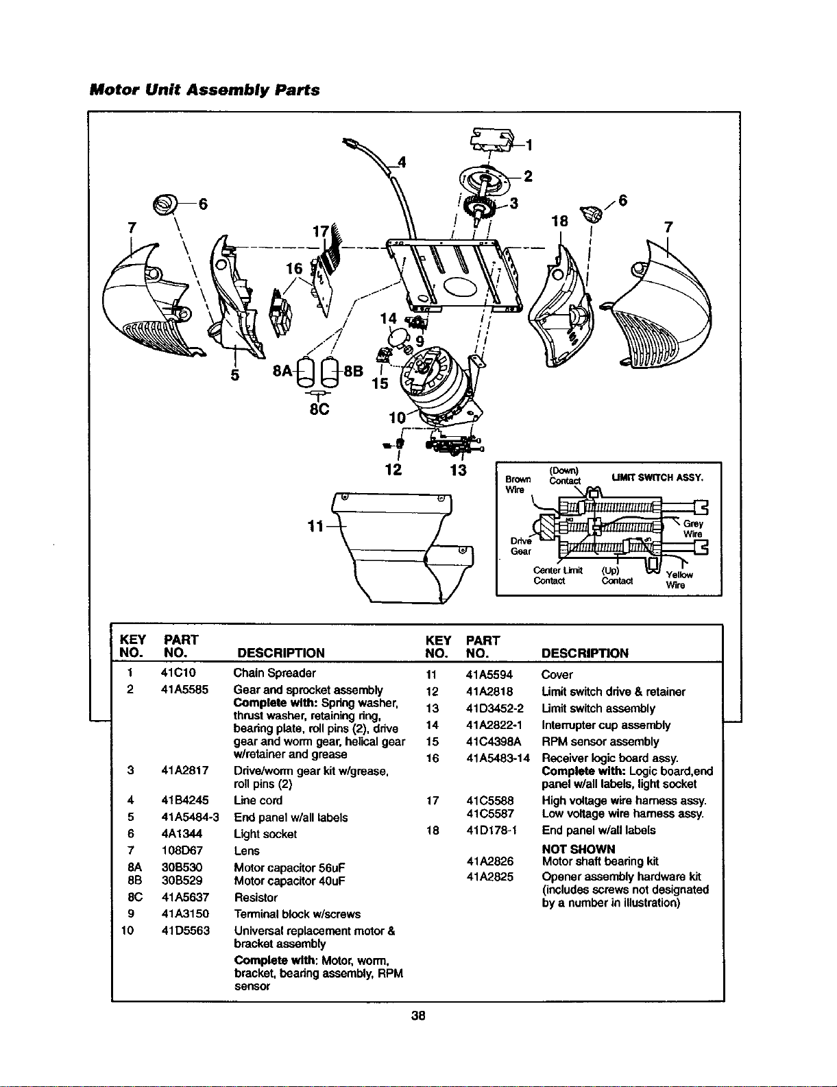
Motor Unit Assembly Parts
7
8C
15
I
12 13 (Down)
Brown Contact LIMITSWITCHASSY,
W_re
Wlr8
G6ar
Center Limit (Up) Yellow
Contact Contact Wire
KEY PART
NO. NO.
1 41C10
2 41A5585
3 41A2817
4 41134245
5 41A5484-3
6 4A1344
7 108D67
8A 3013530
8B 30B529
8C 41A5637
9 41A3150
10 41D5563
KEY PART
DESCRIPTION NO. NO. DESCRIPTION
Chain Spreader
Gear and sprocket assembly
Complete with: Spdng washer,
thrustwasher, retainingdng,
bearing plate, rollpins (2), drive
gear and worm gear, helicalgear
w/retainer and grease
Drive/wormgear kitw/grease,
rollpins (2)
Use cord
End panel w/all labels
Lightsocket
Lens
Motor capacitor56uF
Motor capacitor40uF
Resistor
Terminal block w/screws
11 41A5594
12 41A2818
13 41D3452-2
14 41A2822-1
15 41C4398A
16 41A5483-14
17 41C5588
41C5587
18 41D178-1
41A2826
41A2825
Cover
Umit switchdrive & retainer
Limitswitch assembly
Interruptercup assembly
RPM sensor assembly
Receiver logicboard assy.
Complete with: Logic board,end
panel w/all labels, lightsocket
High voltage wire harness assy.
Low voltage wire harness assy.
End panel w/all labels
NOT SHOWN
Motor shaft bearingkit
Opener assembly hardware kit
(includesscrews notdesignated
by a number in illustration)
Universal replacement motor&
bracketassembly
Complete with: Motor, worm,
bracket, hearing assembly,RPM
sensor
38
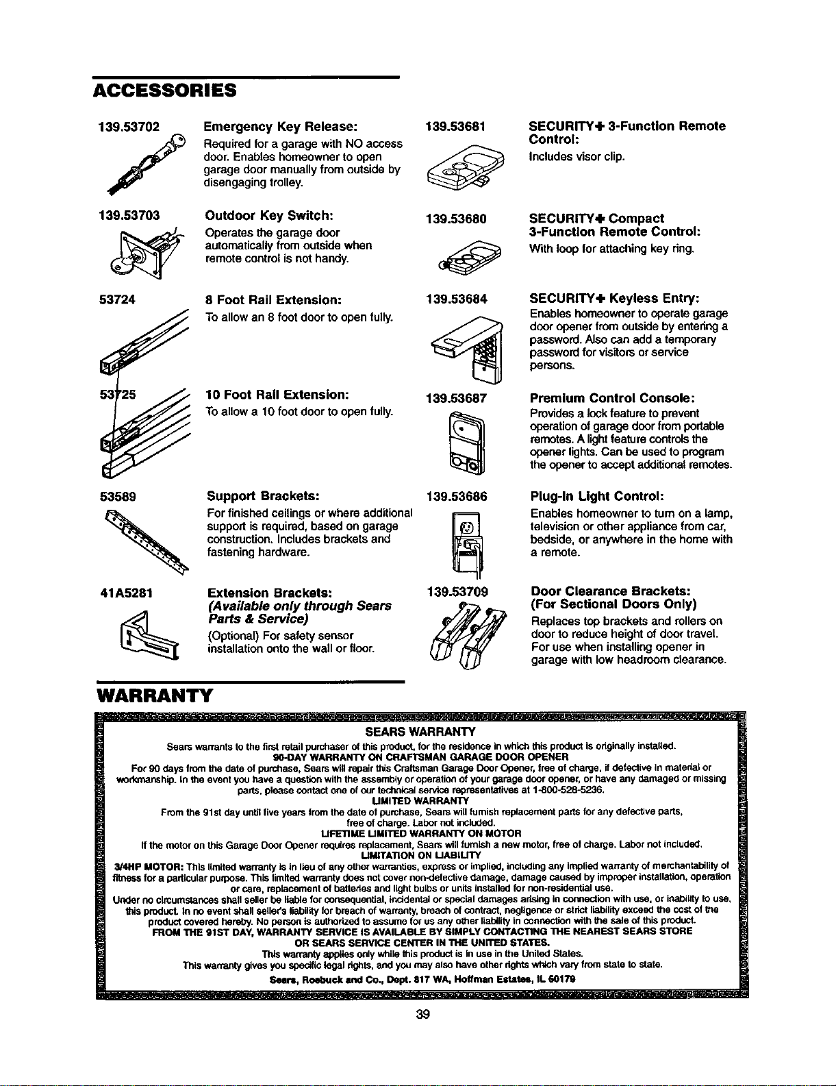
ACCESSORIES
139.53702
139.53703
53724
0s
53 2_
53589
41A5281
Emergency Key Release:
Requiredfor a garage with NO access
door. Enables homeowner to open
garage door manuallyfrom outsideby
disengagingtrolley.
Outdoor Key Switch:
Operates the garage door
automatically from outsidewhen
remotecontrol is nothandy.
8 Foot Rail Extension:
Toallow an 8 font door to open fully.
10 Foot Rail Extension:
Toallow a 10 footdoor to open fully.
Support Brackets:
For finishedceilingsor where additional
supportis required, based on garage
construction,Includes brackets and
fasteninghardware.
Extension Brackets:
(Available only through Sears
Parts & Service)
(Optional) For safety sensor
installationontothe wall or floor.
139.53681
139.53680
139.53684
139,53687
139.53686
139.53709
SECURITY+ 3-Function Remote
Control:
Includesvisor clip.
SECURITY+ Compact
3-Function Remote Control:
With loop forattaching key dng.
SECURITY+ Keyless Entry:
Enableshomeownerto operate garage
dooropenerfrom outsideby enteringa
password.Also san add a temporary
passwordforvisitorsorservice
persons.
Premium Control Console:
Providesa lockfeatureto prevent
operationofgarage doorfromportable
remetes.A lightfeaturecontrolsthe
openerlights.Can be usedto program
the openertoaccept additionalremetes.
Plug-In Light Control:
Enables homeowner to turn on a lamp,
televisionor other appliance fromcar,
bedside, or anywhere in the home with
a remote.
Door Clearance Brackets:
(For Sectional Doors Only)
Replaces top brackets and rollers on
doorto reduce height of doortravel.
For usa when installingopener in
garage with lowheadroom clearance.
WARRANTY
SEARS WARRANTY
Sears warrants to the first retail purchaser of this product, for the residence in whk_ this product isoriginally instatied,
gO-DAY WARRANTY ON CRAFTSMAN GARAGE DOOR OPENER
For 90 days from the date of purchase, Sears will repair this Craftsman Garage Door Opener, tree of charge, if defective in matedai or
wod_manship, in the event you have a question with the a_ssembiy or operation of your garage door opener, or have any damaged or missing
darts, please contact one of our iedmioal service representatives at 1-800-528-5236.
MMt'I1ED WARRANTY
From the 91 st day until five years from the date of purchase, Sears will furnish replacement parts for any defective parts,
free of charge. Labor not included.
MFETIME LIMITED WARRANTY ON MOTOR
if the motor on this Garage Door Opener redalres replacement, Sears wig furnish a new motor, free of charge. Labor not included.
MMITA'FION ON MABILITY
3/4Hp MOTOR: This limited warranty is in lieu of any other warranties, express or implied, including any implied warranty of merchantability of
fitness for a particular purpose. This limited warranty does not cover non-datectise damage, damage caused by improper installation, operation
or care, replacement of batteries and light balbs or units Installed for non-resideatiel use.
Under no circumstances shall seller be liable for consequential, incidental or special damages aristhg In connection with use, Or inability to use,
_ds product. In no event shall setieifs liability for breach of warranty, breach of contract, negligence or strict liability exceed the cost of the
product covered hereby. NO person is authorized to assume for us any other liability in connection with the sale of this product.
FROM THE 91ST DAY, WARRANTY SERVICE IS AVAILABLE BY SIMPLY CONTACTING THE NEAREST SEARS STORE
OR SEARS SERVICE CENTER IN THE UNITED STATES,
This warranty applies only while this product is in use in the United States.
This warranty gives you specific legal fights, and you may also have other rights which ,taP/from state to state.
Sears, Roebuck and Co., Dept. 817 WA, Hoeman Estatu, IL 60179
39