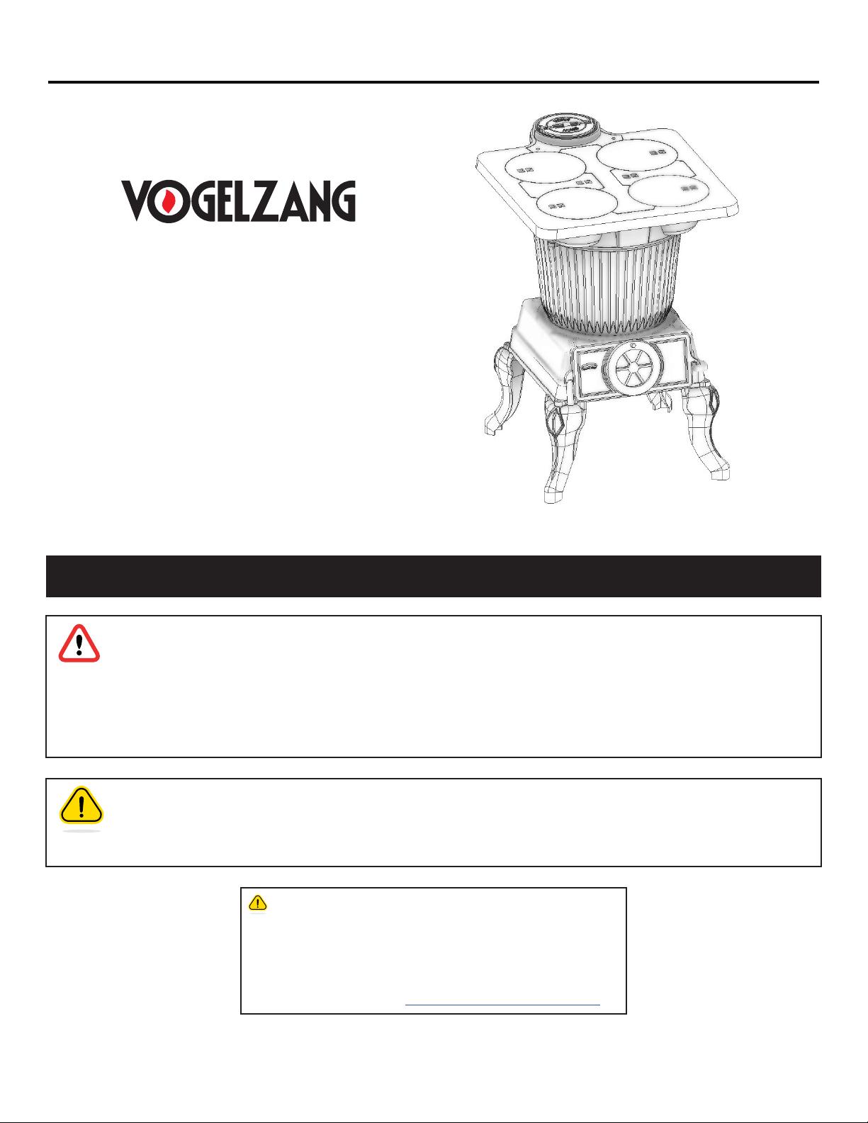
* All Pictures In This Manual Are For Illustrative Purposes Only. Actual Product May Vary.
© 2021 United States Stove Company, 227 Industrial Park Rd., South Pittsburg, TN 37380 Ph. 800-750-2723
THIS MANUAL IS SUBJECT TO CHANGE WITHOUT NOTICE.
Owner’s Instruction and Operation Manual
SAFETY NOTICE: If this heater is not properly installed, a house re may result. For
your safety, follow the installation instructions. Never use make-shift compromises
during the installation of this stove. Contact local building or re ocials about
permits, restrictions and installation requirements in your area. NEVER OPERATE THIS
PRODUCT WHILE UNATTENDED.
CAUTION! Please read this entire manual before you install or use your new stove.
Failure to follow instructions may result in property damage, bodily injury, or even death.
Improper Installation Will Void Your Warranty!
Save These Instructions In A Safe Place For Future Reference.
CALIFORNIA PROPOSITION 65 WARNING:
This product can expose you to chemicals
including carbon monoxide, which is known to the
State of California to cause cancer, birth defects,
and/or other reproductive harm. For more
information, go to www.P65warnings.ca.gov
852603E-0404K
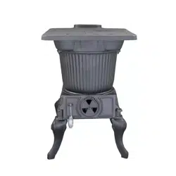
Model Number:
SR57E
COAL ONLY
This stove is not a UL listed stove. DO NOT
USE THIS HEATER IN A MOBILE HOME OR
TRAILER.
The use of wood in this stove, other than for
coal ignition purposes, is prohibited by law.

2
© 2021 United States Stove Company
READ ALL INSTRUCTIONS CAREFULLY
1. The installation of this stove must comply with
your local building code rulings. Please observe
the clearances to combustibles. Do not place fuel,
furniture or any other objects within the clearance
area.
2. Verify that the stove is properly installed before
ring the stove for the rst time. After reading these
instructions, if you have any doubt about your ability
to complete your installation properly, you must obtain
the services of a professional licensed installer familiar
with all aspects of safe and correct installation. DO NOT
USE TEMPORARY OR MAKESHIFT COMPROMISES
during installation. There must be NO DEVIATION
OR ALTERATION OF ANY KIND from the very specic
instructions spelled out in this instruction manual as
it pertains to the installation of this coal-stove. NO
EXCEPTIONS!
3. DO NOT store coal, wood, kindling, ammable liquids
or other combustible materials in the vicinity of the
appliance. Refer to label on back of unit.
4. DO NOT INSTALL THIS STOVE IN A MOBILE HOME,
MANUFACTURED HOME, TRAILER OR TENT NO
EXCEPTIONS!
5. DO NOT ELEVATE THIS STOVE BY ANY MEANS (i.e.
bricks under legs, cement blocks) Stove legs must set
directly upon the solid-surface non-combustible oor
as specied in this stove instruction manual.
6. DO NOT MODIFY THIS STOVE IN ANY WAY! Stove must
be installed with legs provided, attached as shown in
the instructions. Assemble only with original parts as
supplied and shown in this manual.
7. DO NOT OPERATE A STOVE THAT IS MISSING ANY
PARTS! If any parts are missing or defective, please
notify the dealer or manufacturer immediately.
Replace missing, broken or worn parts with factory
original or equivalent parts only.
8. Do not tamper with combustion air controls beyond
normal adjustment capacities.
9. Always connect this stove to a chimney and vent to
the outside. Never vent to another room or inside a
building. DO NOT CONNECT THIS UNIT TO A CHIMNEY
FLUE SERVING ANOTHER APPLIANCE.
10. DO NOT CONNECT THIS COAL BURNING STOVE TO AN
ALUMINIUM TYPE B GAS VENT. This is not safe. Use
a code-approved, lined masonry or a manufactured
chimney system listed to UL 103 HT Residential
Type and Building Heating Appliance Chimney. Use
a 6˝/152mm diameter code-approved chimney with
liner, that is high enough to give a good draft (See
specics in Chimney Connections instructions).
11. Be sure that your chimney is safely constructed and
in good repair. Have the chimney inspected by the re
department or a qualied inspector. Your insurance
company should be able to recommend a qualied
inspector. Chimney connector pipe must be in good
condition. Replace if necessary before using stove.
12. Creosote, soot or y ash may build up in the chimney
connector and chimney and cause a house/building
re. Inspect the chimney connector and chimney
twice monthly during the heating season and clean if
necessary (see Service Hints section in this manual).
13. In the event of a chimney re, turn the air control and
ue damper to closed position, leave the building
and CALL THE FIRE DEPARTMENT IMMEDIATELY!
Have a clearly understood plan on how to handle a
chimney re by contacting your local re authority
for information on proper procedures in the event of
a chimney re. After the re is out, the chimney must
be cleaned and inspected for any stress or cracks
before starting another re. Check the condition of
any combustibles surrounding the chimney.
14. DISPOSAL OF ASHES Ashes should be placed in a steel
container with a tight tting lid and moved outdoors
immediately. The closed container of ashes should be
placed on a noncombustible oor or on the ground,
well away from all combustible materials, pending
nal disposal. If the ashes are disposed of by burial
in soil or otherwise locally dispersed, they should be
retained in the closed container until all cinders have
completely cooled. Other waste shall not be placed in
this container.
15. To prevent injury, do not allow anyone to use this stove
who is unfamiliar with the correct operation of the
stove.
16. Do not operate stove while under the inuence of
drugs or alcohol.
17. The special paints used on your stove may give off
some smoke and an odor while they are curing during
the rst 12 to 15 res. Additional smoke and odor may
be emitted from the light oils used in construction
of the re box. This should disappear after a short
period of time and not occur again. Persons with lung
conditions or owners of susceptible domestic pets
(such as birds) should take prudent precautions. Open
windows and doors as needed to clear smoke and/or
odor. Paint discoloration will occur if the stove is over
red.
SAFETY RULES

© 2021 United States Stove Company
3
18. This stove has a painted surface which is durable
but it will not stand rough handling or abuse. When
installing your stove, use care in handling.
19. Clean exterior with soap and warm water when stove
is not hot. Do not use any acids or scouring soap, as
these solvents wear and dull the nish.
20. CLEAN STOVE FREQUENTLY as soot, creosote and
ash may accumulate. Empty ash pan frequently. Build-
up of ash can block air ow to the re and/or damage
the grate. Dispose of ash properly (see #14.)
21. ALERT ALL PERSONS TO THE HAZARDS OF HIGH
SURFACE TEMPERATURES while stove is in operation
– especially young children. Keep away from a hot
stove to avoid burns or clothing ignition.
22. NEVER LEAVE SMALL CHILDREN UNSUPERVISED
WHEN THEY ARE IN THE SAME ROOM AS THE STOVE.
If small children will be in the same room as the stove
during operation, provide a sturdy barrier to keep them
at a safe distance from the stove.
23. Keep stove area clear and free from al l combustible
materials, gasoline, engine oil, naphtha and other
ammable vapors and liquids.
24. WHILE TENDING THE FIRE ALWAYS WEAR
PROTECTIVE CLOTHING, re retardant hearth gloves
and eye protection, to prevent burns.
25. Never operate this stove without the ash clean-out
door open or ash drawer removed. Such actions can
result in very dangerous operating conditions.
26. DO NOT OVER FIRE THE STOVE. Over ring will occur
if combustion air is uncontrolled as when ash clean-
out door is left open during operation. Such actions
can result in very dangerous operating conditions.
While in operation, keep the ash clean-out drawer in
place and the ash door closed and secured at all times
except while tending the re.
27. Do not load the fuel to a height or in such manner that
it would be hazardous when opening the lids.
28. NEVER LEAVE THE STOVE UNATTENDED when the
door is open. Always close the door after ignition.
29. DO NOT CONNECT TO OR USE IN CONJUNCTION
WITH ANY AIR DISTRIBUTION DUCT WORK
UNLESS SPECIFICALLY APPROVED FOR SUCH
INSTALLATIONS.
30. THIS STOVE MUST NEVER BE INSTALLED IN A
HALLWAY OR NEAR A STAIRCASE, as it may block
egress in the event of a re.
31. DO NOT INSTALL IN AN ALCOVE OR INSIDE A
FIREPLACE.
32. Install at least one smoke detector on each oor of
your home. Detectors should be located away from
the heating appliance to avoid false alarms. Detectors
should be located close to sleeping areas. Follow
the smoke detectors manufacturer’s placement and
installation instructions. Maintain smoke detector per
manufacturer’s instructions.
33. CARBON MONOXIDE (CO) HAZARD. A build-up of CO
fumes is toxic and can be fatal. Carbon Monoxide is a
colorless, odorless gas produced during combustion
of wood, coal, oil, gas and by other fuel burning
appliances. It is important to have a proper draft
and adequate replacement air ventilation so fumes
are drawn out the chimney. Installed as instructed
this stove is designed to be as safe as possible yet
it is recommended to install a CO detector. Follow
the manufacturer’s recommendations for proper
installation and use. It is recommended to be placed
at table-top level (not near the ceiling) to avoid false
alarms. Realize that devices other than a stove (i.e.
motor exhaust) can trigger CO alarms. If alarm sounds:
• Recognize the symptoms of CO poisoning (headaches,
nausea & drowsiness).
• Increase ventilation (open windows & doors).
• Make sure stove doors and/or lids are closed and
secured.
• Check stove for smoking or pung (open airow
controls).
• Check chimney & connector pipe for leaks, blockage or
down-draft conditions.
• Check CO device for false alarm.
34. Keep power cords, electrical appliances and/or
assemblies outside of the clearance area shown in
this manual for combustible materials.
35. Consult your municipal building department or re
ocials about restrictions, permits and installation
requirements for your area.
36. For further information on using your stove safely,
obtain a copy of the National Fire Protection
Association (NFPA) publication, “Using Coal and Wood
Stoves Safely” NFPA No. HS-10- 1978. The address of
the NFPA is Batterymarch Park, Quincy, MA 02269.
NOTE:
A PROFESSIONAL, LICENSED HEATING AND COOLING
CONTRACTOR MUST BE CONSULTED IF YOU HAVE
QUESTIONS REGARDING THE INSTALLATION OF THIS
SOLID FUEL BURNING APPLIANCE.
SAFETY RULES

4
© 2021 United States Stove Company
NOTICE: Vogelzang International Corporation grants
no warranty, stated or implied, for the installation
or maintenance of your coal stove and assumes no
responsibility of any incidental or consequential damages.
TOOLS REQUIRED
• Safety Glasses
• Hearth Gloves
• Pencil
• 6 foot Folding Rule or Tape Measure
• Tin Snips
• Drill: Hand or Electric 1/8” dia. Drill Bit (sheet metal
screws)
• Screwdrivers (blade and phillips types)
• 13mm Nut Driver or Ratchet with 13mm Socket (for
13mm Hex Nuts)
• 13mm Nut Driver or Ratchet with 13mm Socket (for
Stove Bolts)
MATERIALS REQUIRED
• Flooring Protection: 56˝ x 59˝ as specied Chimney
Connection: 6˝ black steel (24 ga. min.) straight or elbow
(as required)
• 1/2˝ Sheet Metal Screws
• Chimney: Existing 6˝ Code-approved,
• Lined Masonry Chimney or 6˝ Inside Diameter
manufactured chimney system listed to UL 103 HT.
• Furnace Cement (manufacturer recommends Rutland
Code 78 or equivalent)
CAUTION:
STOVE IS HEAVY. MAKE SURE YOU HAVE ADEQUATE
HELP AND USE PROPER LIFTING TECHNIQUES
WHENEVER MOVING STOVE.
Refer to diagram and parts lists at back of this manual.
1. Uncrate the stove and remove cardboard packing
and protective poly bag (save cardboard for further
assembly).
2. Remove parts from inside of stove. Parts include: four
lids (#1), three lid supports (#4 & #5), one ash door
(#14), one lid lifter (#16), four legs (#15), hardware
pack (#17), and Spring Handle (#12) and draft damper
(#18).
3. Place attened carton on oor and carefully turn stove
over onto carton.
4. Attach the legs to base of stove with stove bolts.
5. Carefully lift stove upright and place in desired location
(see following instructions for properly locating stove).
6. Place lid supports and four lids in position on stove
top.
7. Lower ash door into position.
8. The ue pipe draft damper (#18) must be installed into
the top end of the rst straight section of stove pipe
(gure1) exiting the stove before the stove is used.
a. Drill two 1/4” holes centered on either side of the pipe
section 6” from the top end of the pipe Remove the
handle from the damper then slide the damper into the
pipe.
b. Align the damper with the holes drilled in step 8a and
insert the handle through the holes and the damper.
NOTE: This damper is necessary for the proper operation
of the stove and to meet EPA emissions requirements for
heating appliances. It must be installed before use (No
exceptions)
9. Attach stove piping — see instructions.
6"/15.25 cm
Draft Damper
Installation
ASSEMBLY INSTRUCTIONS

© 2021 United States Stove Company
5
INSTALLATION
CLEARANCE TO COMBUSTIBLE
36"
36"
CORNER CLEARANCES
Top View Minimum
Corner Clearances from
Combustible Surfaces
BACKWALL
COMBUSTIBLE
CONSTRUCTION
ACCORDING TO
NFPA 211
SIDEWALL
COMBUSTIBLE
CONSTRUCTION
ACCORDING TO
NFPA 211
DASHED LINE SHOWS
HORIZONTAL CHIMNEY
CONNECTOR AND
ADDITIONAL FLOOR
PROTECTION REQUIRED
FLOOR
PROTECTOR
(TOP VIEW) (FRONT VIEW) (SIDE VIEW)
CEILING
BACKWALL
SIDEWALL
CEILING
36”
36”
59”
18”
18”
18”
18”
FLOOR PROTECTOR
Minimum
Floor-to-ceiling
Height
8ft / 2.4m
18”
18”
36”
56”
36”
36"
36"
CORNER CLEARANCES
Top View Minimum
Corner Clearances from
Combustible Surfaces
BACKWALL
COMBUSTIBLE
CONSTRUCTION
ACCORDING TO
NFPA 211
SIDEWALL
COMBUSTIBLE
CONSTRUCTION
ACCORDING TO
NFPA 211
DASHED LINE SHOWS
HORIZONTAL CHIMNEY
CONNECTOR AND
ADDITIONAL FLOOR
PROTECTION REQUIRED
FLOOR
PROTECTOR
(TOP VIEW) (FRONT VIEW) (SIDE VIEW)
CEILING
BACKWALL
SIDEWALL
CEILING
36”
36”
59”
18”
18”
18”
18”
FLOOR PROTECTOR
Minimum
Floor-to-ceiling
Height
8ft / 2.4m
18”
18”
36”
56”
36”
Proper clearances must be maintained for adequate air
circulation. Adequate ventilation must be provided while
operating this stove.
1. The stove must be placed on solid concrete, solid
masonry, or when installed on a combustible oor a
solid surface oor protector listed to UL1618 Type
2 with a minimum of 1˝ thick and a R-value of 3.0 or
greater must be used, such as Hy-C or Imperial Model
UL 5460BK (NOTE: To calculate R-values of equivalent
alternative materials). The base must extend at least
18” beyond the front, rear and sides of the stove, and
must extend underneath and 2˝ beyond each side of
horizontal connector pipe if it is elbowed towards a
wall (see gure 5 and consult local building codes and
re protection ordinances.)
2. The stove must have its own ue. DO NOT CONNECT
THIS UNIT TO A CHIMNEY FLUE SERVING OTHER
APPLIANCES.
3. After observing the clearances to combustible
materials (gure 2 – 4), locate your oor protector
accordingly (gure 2) and carefully place the stove in
your selected location. Install stove pipe, elbows, and
thimble as required, utilizing either a recently cleaned
and inspected 6˝/152mm masonry chimney or a
6˝/152mm I.D. manufactured chimney system listed
to UL 103 HT. Maximum 64 square inches.
4. Use 6˝/152mm diameter minimum 24 MSG Black or 26
MSG Blue round stove pipe. DO NOT USE GALVANIZED
duct pipe. Secure pipe sections with three (3) sheet
metal screws in each stove pipe and/or elbow joint to
rmly hold the pipe sections together. Screws may be
no more than a maximum of 3˝/76mm apart. DO NOT
CONNECT THIS STOVE TO ANY AIR DISTRIBUTION
OR DUCT SYSTEM.
5. Recheck clearances from the stove, connector stove
pipe, and corner clearances using the illustrations and
your local building codes or re protection ordinances.
NOTE: Drywall faced with brick or stone MUST be
considered a combustible surface.
6. DO NOT INSTALL THIS STOVE IN A MOBILE HOME,
MANUFACTURED HOME, TENT OR TRAILER (NO
EXCEPTIONS)
7. The clearances provided are minimum dimensions.
Installation of this stove must comply with your local
building code rulings.
8. This stove is NOT a UL listed stove.
36"
36"
CORNER CLEARANCES
Top View Minimum
Corner Clearances from
Combustible Surfaces
BACKWALL
COMBUSTIBLE
CONSTRUCTION
ACCORDING TO
NFPA 211
SIDEWALL
COMBUSTIBLE
CONSTRUCTION
ACCORDING TO
NFPA 211
DASHED LINE SHOWS
HORIZONTAL CHIMNEY
CONNECTOR AND
ADDITIONAL FLOOR
PROTECTION REQUIRED
FLOOR
PROTECTOR
(TOP VIEW) (FRONT VIEW) (SIDE VIEW)
CEILING
BACKWALL
SIDEWALL
CEILING
36”
36”
59”
18”
18”
18”
18”
FLOOR PROTECTOR
Minimum
Floor-to-ceiling
Height
8ft / 2.4m
18”
18”
36”
56”
36”
MINIMUM CLEARANCES TO
COMBUSTIBLE SURFACES
Unit to Sidewall 36”
Unit to Backwall 36”
Unit Corner to Wall 36”
Pipe Connector to Backwall 38”
Pipe Connector to Ceiling 18”

6
© 2021 United States Stove Company
NOTE: Connector pipe is not included. To purchase pipe,
visit your local Hardware, home or building center. See
“locating stove” for Additional specications.
1. Slide the lower end of the stove pipe into the ue
outlet collar as shown. Note: The crimped end of the
stove-pipe slides into the cast iron ue collar at top
rear of stove. Secure stove pipe to ue collar with at
least three (3) sheet metal screws and seal with stove
cement.
2. Horizontal pipe runs must slope upwards towards the
chimney at least 1/4” per foot of horizontal run.
3. You must have at least 18 inches of clearance between
any horizontal piping and the ceiling.
4. The pipe cannot extend into the chimney ue.
5. Secure pipe/elbow sections with three (3) sheet metal
screws at each joint to make the piping rigid. Secure
pipe/elbow sections with a minimum of three (3)
equally spaced sheet metal screws at each joint and
at the stove collar to make the pipe rigid.
6. It is recommended that no more than two (2) 90 degree
bends be used in the stove-pipe installation. The use
of more than two 90 degree bends may decrease the
amount of draw and possibly cause smoke spillage.
Where possible, use only corrugated (non-adjustable)
elbows. These provide a better seal.
7. The connector pipe must not pass through an attic or
roof space, trusses, closet, or any concealed space,
or oor, ceiling, wall or combustible construction (See
Chimney Connector Systems & Clearances) A UL 103
HT listed chimney system must be used from the rst
penetration of ceiling or wall to the chimney cap. Use
chimney components from a single manufacturer. Do
not mix brands.
CORRECT WRONG WRONG
Flue Outlet Collar
Stovepipe/Flue Connections
WARNING:
DO NOT USE SINGLE WALL CONNECTOR PIPE AS A
CHIMNEY - A HOUSE FIRE COULD RESULT.
CAUTION:
KEEP FURNISHINGS AND OTHER COMBUSTIBLE
MATERIALS AWAY FROM THE STOVE.
CORRECT WRONG WRONG
Stovepipe/Flue Connections
Hand-form pipe to oval shape
Flue Outlet Collar
INSTALLATION

© 2021 United States Stove Company
7
The stove must be connected to either a code approved,
lined masonry or manufactured metal chimney built and
tested to the specications listed on the previous pages.
Chimneys perform two functions:
1. As a means of exhausting smoke and ue gases
which are the result of fuel combustion.
2. The chimney provides “draft” which allows oxygen to
be continuously introduced into the appliance, so that
proper combustion is possible.
This stove relies on natural draft to operate.
NOTICE: Always provide a source of fresh air into the
room where the stove is located. Failure to do so may
result in air starvation of other fuel burning appliances
and the possible development of hazardous conditions,
re or death.
DRAFT: Your stove itself does not create draft. Draft
is provided by the chimney. To achieve proper draft
your chimney must meet the three minimum height
requirements detailed below. A minimum of 0.05 w.c
(Measured in water column) is required for proper
drafting to prevent back pung, smoke spillage, and to
maximize performance. Draft must not exceed 0.06 w.c.
or unsafe operating conditions may occur. A barometric
draft regulator must be installed if draft exceeds 0.06 w.c.
(Gauges to measure draft are readily available at stove
stores and are economical to rent or purchase.)
Factors such as wind, barometric pressure, trees, terrain
and chimney temperature can have an adverse effect on
the draft. The manufacturer cannot be held responsible for
external factors leading to less than optimal drafting.
Should you have a problem with inadequate draft, you
should contact a licensed heating and cooling contractor
for assistance in solving the problem.
IMPORTANT INSTALLATION POINTS
1. Size chimney ue to stove collar. This stove requires a
6” diameter ue.
2. Never connect this unit to a chimney serving another
appliance.
3. The chimney must meet all minimum height
requirements.
4. Never use a chimney to ventilate a cellar or basement.
5. Contact your local building authority for approved
methods of installation and any necessary permits
and/or inspections.
MASONRY CHIMNEY
Chimney must be a code-approved, masonry chimney with
ue liner. Before using an existing masonry chimney, clean
the chimney, inspect the ue liner and make any repairs
needed to be sure it is safe to use. Make repairs before
attaching the stove. The connector stove pipe and ttings
you will need to connect directly to a masonry chimney are
shown in.
If the connector stove pipe must go through a combustible
wall before entering the masonry chimney, consult a
qualied mason or chimney dealer. The installation must
conform to local building and re codes and latest edition
of NFPA 211. If there is a cleanout opening in the base of
the chimney, close it tightly.
5/8" TILE
CHIMNEY
LINER
CHIMNEY
FLUE
THIMBLE
COLLAR
8” MIN.
LINER
BELOW
ENTRY
HOLE
6” ROUND
24 GA. BLACK
CONNECTOR
STOVEPIPE
MASONRY
CHIMNEY
Masonry Chimney Connection
MANDATORY
CHIMNEY CAP
FLOOR PROTECTOR
UL 103HT
CHIMNEY
2 ft min.
10 ft
3 ft min.
11 ft min.
CONNECTOR
PIPE
REFER TO CHIMNEY
MANUFACTURER’S
PARTS AND
INSTRUCTIONS
INSTALLATION

8
© 2021 United States Stove Company
MANUFACTURED CHIMNEY
Refer to chimney and chimney connector maker’s
instructions for installation and use. Use only a 6˝
diameter manufactured chimney system listed to UL 103
HT. Chimney made to this listing is High Temperature
rated to 2100 degrees Fahrenheit. Use chimney from only
one manufacturer. Never mix brands. Carefully follow
the chimney manufacturer’s stated requirements and
clearances. Use the chimney manufacturer’s attic guards,
roof supports, ashing and re stops when passing through
a ceiling. Use a listed thimble when passing through a
combustible wall. Do not use makeshift compromises
during installation.
WARNING:
DO NOT USE SINGLE WALL CONNECTOR PIPE AS A
CHIMNEY - A HOUSE FIRE COULD RESULT.
When using a pre-existing chimney, have it’s condition
and installation inspected before using. Make sure that
the chimney meets all of the UL rating requirements
listed above. Be aware that not all manufactured chimney
is of the UL 103 HT type. NOTE: It is recommended that
you contact a licensed heating and cooling contractor
(consult your local yellow pages) for chimney installation.
Manufactured chimney with the proper required UL listing
is available from most home centers, hardware stores, and
HVAC supply stores. If you have access to the internet, you
may wish to view chimney manufacturers’ information on-
line.
MANDATORYCHIMNEY CAP
FLOOR PROTECTOR
2 ft min.
10 ft
3 ft min.
11 ft min.
ELBOW
MINIMUM
CLEARANCE
18”
CLASS A
LISTED HT
INCLUDING
WALL THIMBLE
COLLAR
THIMBLE
NON
COMBUSTIBLE
WALL
CONNECTOR PIPE
MANDATORY
CHIMNEY CAP
FLOOR PROTECTOR
Chimney Construction Through Roof
UL 103HT
CHIMNEY
2 ft min.
10 ft
3 ft min.
11 ft min.
PIPE
REFER TO CHIMNEY
MANUFACTURER’S
PARTS AND
INSTRUCTIONS
VENTING TO EXISTING FIREPLACE
In some instances, people desire to convert an existing
replace for stove use. Usually, safe connection to an
existing masonry chimney requires more work than using
a prefabricated chimney. The existing replace must be
closed and sealed at the damper with high temperature
caulk, ceramic wool, or furnace cement. Prior to
installation, clean and inspect the existing ue and smoke
shelf. Installation should be designed so the system
can be dismantled for periodic cleaning and inspection.
Before conversion, make sure the existing chimney is
structurally sound, the chimney incorporates a ue liner
and make sure it is in good condition (A ue liner consists
of clay tile that protects the brickwork of a chimney. If a
chimney does not have a liner, or it is damaged, have it
relined by a professional. DO NOT USE a chimney that is
unlined or damaged!) If you have any question regarding
the condition of the chimney, consult a qualied licensed
contractor, qualied engineer, competent mason, certied
Chimney Sweep, or a knowledgeable inspector. Consult
your insurance company if you cannot nd a qualied
expert.
CAUTION:
NOT ALL FIREPLACE CHIMNEYS ARE SUITABLE FOR
CONVERSION TO ACCOMMODATE CONNECTION TO A
COAL STOVE. CHECK WITH A QUALIFIED EXPERT.
INSTALLATION

© 2021 United States Stove Company
9
Many prefabricated replaces are of the “zero clearance
replace” category. These consist of multi layered metal
construction. They are designed with enough insulation
and/or air cooling on the base, back and sides so they can
be safely installed in direct contact with combustible oors
and walls. Although many prefabricated replaces carry
endorsements from nationally recognized organizations
for use as replaces, they have not been tested for
connection to coal stove heaters. Connecting a stove
to such a device will void the manufacturer’s warranty.
Venting a stove directly into a replace does not meet
code and should not be attempted. The stove warranty will
be void with such an installation. Do not create a hazard in
your home by connecting in this manner.
FIREPLACE INSTALLATION
Directly connecting the stove-pipe into the existing
masonry chimney (“Type A” Fireplace Conversion) of the
replace is the ONLY approved method of installation. If
the chimney is behind a combustible wall, you must use
an approved wall pass-through system to gain access to
the chimney. This is a complicated and involved process
and to ensure safety should only be done by a qualied
installer.
1. An entry hole must be cut through the masonry and
tile liner with minimal damage to the liner. At least
8” of liner must remain below the entry position.
When locating the stove and stove-pipe, all minimum
clearances must be observed from combustible
surfaces including mantels, combustible trim work,
ceilings and walls. Positioning the center of the stove
pipe entry into the chimney 24˝ below the ceiling
should ensure proper clearance for a 6˝ stove-pipe.
2. Install a re clay (5/8˝ minimum thickness) thimble.
Make sure the thimble is ush with the inner surface
of the chimney liner and does not protrude into the
ue.
3. Secure the thimble with refractory mortar. The thimble
should be surrounded by 12˝ of solid unit masonry
brickwork or 24˝ of stone.
4. Install the stove-pipe into the thimble as far as possible
without extending past the ue lining.
5. A small airspace (about 1/2˝) should remain between
the stove-pipe and thimble to allow for expansion of
the pipe. Seal this airspace with high temperature
caulking or ceramic wool.
6. Secure and seal the damper in the closed position
using high-temp caulking, ceramic wool, or furnace
cement. Also check to see if the chimney has a clean-
out. If it does, make sure it is closed and sealed as well.
A leaky clean-out will greatly reduce draft eciency.
STOVEPIPE CONNECTOR
SEALED AT THIMBLE
5/8” FIRECLAY
FLUE LINER
CHIMNEY
LINER EXTEND A
MINIMUM OF 8”
BELOW PIPE
CONNECTION
TO CHIMNEY
DAMPER
THROAT CLOSED
AND SEALED
HORIZONTAL 6” BLACK STOVEPIPE
(24 GA.) WITH 1/4”RISE PER FOOT
6” BLACK STOVEPIPE ELBOW
6” BLACK STOVEPIPE
USE HREE SHEET METAL
SCREWS PER JOINT
OF STOVEPIPE
LISTED FLOOR
PROTECTOR
COMBUSTIBLE WALL CHIMNEY CONNECTOR
PASS-THROUGHS
Method A. 12” (304.8 mm) Clearance to Combustible
Wall Member: Using a minimum thickness 3.5” (89 mm)
brick and a 5/8” (15.9 mm) minimum wall thickness clay
liner, construct a wall pass-through. The clay liner must
conform to ASTM C315 (Standard Specication for Clay
Fire Linings) or its equivalent. Keep a minimum of 12”
(304.8 mm) of brick masonry between the clay liner and
wall combustibles. The clay liner shall run from the brick
masonry outer surface to the inner surface of the chimney
ue liner but not past the inner surface. Firmly grout or
cement the clay liner in place to the chimney ue liner.
Method B. 9” (228.6 mm) Clearance to Combustible Wall
Member: Using a 6” (152.4 mm) inside diameter, listed,
factory-built Solid-Pak chimney section with insulation
of 1” (25.4 mm) or more, build a wall pass-through with a
minimum 9” (228.6 mm) air space between the outer wall
of the chimney length and wall combustibles. Use sheet
INSTALLATION

10
© 2021 United States Stove Company
INSTALLATION
metal supports fastened securely to wall surfaces on all
sides, to maintain the 9” (228.6 mm) air space. When
fastening supports to chimney length, do not penetrate the
chimney liner (the inside wall of the Solid-Pak chimney).
The inner end of the Solid-Pak chimney section shall be
ush with the inside of the masonry chimney ue, and
sealed with a non-water soluble refractory cement. Use
this cement to also seal to the brick masonry penetration.
Method C. 6” (152.4 mm) Clearance to Combustible
Wall Member: Starting with a minimum 24 gage (.024”
[.61 mm]) 6” (152.4 mm) metal chimney connector, and
a minimum 24 gage ventilated wall thimble which has
two air channels of 1” (25.4 mm) each, construct a wall
pass-through. There shall be a minimum 6” (152.4) mm
separation area containing berglass insulation, from the
outer surface of the wall thimble to wall combustibles.
Support the wall thimble, and cover its opening with a
24-gage minimum sheet metal support. Maintain the 6”
(152.4 mm) space. There should also be a support sized
to t and hold the metal chimney connector. See that
the supports are fastened securely to wall surfaces on
all sides. Make sure fasteners used to secure the metal
chimney connector do not penetrate chimney ue liner.
Method D. 2” (50.8 mm) Clearance to Combustible Wall
Member: Start with a solid-pak listed factory built chimney
section at least 12” (304 mm) long, with insulation of 1”
(25.4 mm) or more, and an inside diameter of 8” (2 inches
[51 mm] larger than the 6” [152.4 mm] chimney connector).
Use this as a pass-through for a minimum 24-gauge single
wall steel chimney connector. Keep solid-pak section
concentric with and spaced 1” (25.4 mm) off the chimney
connector by way of sheet metal support plates at both
ends of chimney section. Cover opening with and support
chimney section on both sides with 24 gage minimum
sheet metal supports. See that the supports are fastened
securely to wall surfaces on all sides. Make sure fasteners
used to secure chimney ue line.
NOTES:
• Connectors to a masonry chimney, excepting method B,
shall extend in one continuous section through the wall
pass-through system and the chimney wall, to but not
past the inner ue liner face.
• A chimney connector shall not pass through an attic or
roof space, closet or similar concealed space, or a oor,
or ceiling.

© 2021 United States Stove Company
11
CAUTION: HOUSE FIRE HAZARDS
• GASSES EMITTED FROM FRESHLY ADDED COAL
MUST BE BURNED OR THEY WILL ACCUMULATE
AND EXPLODE. NEVER SMOTHER A FIRE WHEN
ADDING FRESH COAL.
• NEVER USE MANUFACTURED “COAL BRICKS”
MADE OF COAL DUST AND WAX-TYPE BINDER.
• DO NOT STORE COAL ON FLOOR PROTECTOR,
UNDERNEATH STOVE PIPE OR ANYWHERE WITHIN
MINIMUM CLEARANCES FROM COMBUSTIBLE
SURFACES SPECIFIED FOR THIS STOVE (36”)
• OVER FIRING MAY CAUSE A HOUSE FIRE. YOU
ARE OVER FIRING IF THE STOVE OR CHIMNEY
CONNECTOR GLOWS RED.
• BUILD FIRES ONLY ON INTEGRAL GRATE INCLUDED
WITH THE STOVE.
WARNING: EXPLOSION HAZARD
• NEVER USE CHEMICALS, GASOLINE, GASOLINE-
TYPE LANTERN FUEL, KEROSENE, NAPHTHA,
CHARCOAL LIGHTER FLUID, OR SIMILAR
FLAMMABLE LIQUIDS TO START OR “FRESHEN-
UP” A FIRE IN THE STOVE.
• KEEP ALL FLAMMABLE LIQUIDS, ESPECIALLY
GASOLINE, OUT OF THE VICINITY OF THE STOVE —
WHETHER IN USE OR IN STORAGE.
• DO NOT STORE COAL ON FLOOR PROTECTOR,
UNDERNEATH STOVE PIPE OR ANYWHERE WITHIN
MINIMUM CLEARANCES FROM COMBUSTIBLE
SURFACES SPECIFIED FOR THIS STOVE (36”)
• OVER FIRING MAY CAUSE A HOUSE FIRE. YOU
ARE OVER FIRING IF THE STOVE OR CHIMNEY
CONNECTOR GLOWS RED.
• BUILD FIRES ONLY ON INTEGRAL GRATE INCLUDED
WITH THE STOVE.
OPERATING SAFETY PRECAUTIONS
1. Stove is hot while in operation. Keep children, clothing,
and furniture away from hot stove. Contact may cause
skin burns. Do not touch the stove after ring until it
has cooled.
2. Never over re this stove by building excessively hot
res as a house/ building re may result. You are over
ring the stove if stove or stove pipe begins to glow or
turn red.
3. Never build extremely large res in this type of stove
as damage to the stove or smoke leakage may result.
4. Provide air into the room for proper combustion.
5. Inspect stove-pipe every 60 days. Replace immediately
if stove-pipe is rusting or leaking smoke into the room.
FOR USE WITH SOLID COAL FUEL ONLY
Chestnut, egg stove or nut-sized coal for residential
furnaces or any of the specialty packaged replace coals
(not wax-type “Coal Bricks”) can be used. Low ash content
(2% to 6%) coal is recommended.
NOTICE:
USE SOLID COAL MATERIALS ONLY. FOR BEST RESULTS
WHEN BURNING COAL, USE SOLID, BITUMINOUS
COAL. NEVER USE MANUFACTURED COAL “BRICKS”
MADE OF COAL DUST AND WAX-TYPE BINDER. STORE
COAL IN DRY, WELL VENTILATED AREA. DO NOT BURN
GARBAGE, CHARCOAL OR FLAMMABLE LIQUIDS SUCH
AS GASOLINE, NAPHTHA OR ENGINE OIL.
LIGHTING
1. Open ue draft damper fully to provide maximum
draft.
2. Remove lid(s) and place several wads of crushed
paper in the rebox.
3. Lay small stacks of kindling on the paper to start the
re.
4. Light the paper and kindling and replace the lid(s).
Make sure they are seated properly. Keep ash door
closed when stove is in use.
5. Add fuel after re is burning briskly. Use care not to
smother the kindling re when adding fuel. Replace
the lid(s) and make sure they are seated rmly.
6. Adjust the draft damper and spin draft control. The
more closed the spin draft is set, the lower and slower
the re will burn. The more open, the faster and hotter
the re will burn. Do not over-re the stove.
7. NEVER build extremely large res in this type of stove
as damage to the stove or smoking may result. If you
have too much draft, then regulate the draft with the 6˝
stove pipe damper.
8. DO NOT TOUCH – SEVERE BURNS MAY RESULT! After
ring DO NOT TOUCH STOVE until it has cooled.
9. Replace lid(s) and make sure they are seated properly..
10. This is a cast iron stove. It does NOT have welded
seams. From time to time you may need to “tune-
up” the stove by relling and/or replacing the stove
cement/ mortar along the seams.
OPERATING INSTRUCTIONS

12
© 2021 United States Stove Company
ADDING FUEL
Add small amounts of fuel each hour or so instead of
piling large quantities of fuel at one time. This will ensure
a more complete combustion process and less build-up of
tars, soot, or creosote will occur in the chimney.
1. Always open ue draft damper before removing the
lids.
2. When adding fuel be careful not to smother the re.
3. Replace lids and seat securely.
4. Adjust the ue damper and spin draft controls.
5. Empty ashes regularly. Do not allow ashes to pile
up higher than the top of the hearth (see Safety
Instructions). If ashes build up to the grate, burnout
will occur.
6. Properly dispose of hot ashes (see Safety Instructions)
7. Do not over re the stove.
CAUTION:
DO NOT OVER FIRE APPLIANCE. TOO MUCH FUEL
OR BURNING PROHIBITED MATERIALS SUCH AS
TRASH OR FLAMMABLE LIQUIDS MAY CAUSE OVER
FIRING. YOU ARE OVER FIRING IF ANY PART OF THE
STOVE OR THE CHIMNEY CONNECTORS GLOWS RED.
IMMEDIATELY CLOSE THE DOOR, SPIN DRAFT AND
FLUE DAMPER TO REDUCE THE AIR SUPPLY TO THE
FIRE. THIS WILL SLOW DOWN THE FIRE.
CAUTION:
SLOW BURNING FIRES AND EXTENDED USE MAY
CAUSE EXCESSIVE CREOSOTE BUILD-UP. IGNITION OF
CREOSOTE BUILD-UP OR OVER FIRING MAY CAUSE
A CHIMNEY FIRE. CHIMNEY FIRES BURN EXTREMELY
HOT AND MAY IGNITE SURROUNDING MATERIALS.
IN CASE OF A CHIMNEY FIRE LEAVE THE BUILDING
AND CALL THE FIRE DEPARTMENT FROM A SAFE
LOCATION.
ASH DISPOSAL
While in use, empty ash pan regularly. Too much ash
accumulation can restrict airow to the re and damage the
grate. Dispose of ashes properly (See Safety Instructions)
CHIMNEY DRAFT
Draft is a function of the chimney, not the stove — do not
expect the stove to draw. Smoke spillage into the house
or excessive build-up of condensation or creosote in the
chimney are warnings that the chimney is NOT functioning
properly. Correct the problem before using the stove.
Following are some possible causes for improper draft.
1. The connector stove pipe may be pushed into the
chimney too far, stopping the draft.
2. If the chimney temperature is too cool, water will
condense in the chimney and run back into the stove.
Creosote formation will be rapid and may block the
chimney. Operate the stove at a re level high enough
to keep the chimney warm to prevent condensation
from forming.
3. If the re burns well but sometimes creates excess
smoke or burns slowly, it may be caused by the
chimney top being lower than another part of the
house or a nearby tree. The wind blowing over a house
or tree, falls on top of the chimney like water over a
dam, beating down the smoke. The top of the chimney
should be at least three (3) feet above the roof and be
at least two (2) feet higher than any point of the roof
within ten (10) feet.
CREOSOTE – FORMATION AND NEED FOR
REMOVAL
Failure to remove creosote may result in ignition and may
cause a house/building re. Creosote may be removed
using a chimney brush or other commonly available
materials from your local hardware retailer.
PREVENTING CREOSOTE BUILDUP
1. Creosote will inevitably form in your chimney and
connector pipe. Following these steps will help reduce
the rate of build up.
Avoid smothering the re with too much fuel. Too much
fuel loaded at one time will create heavy, volatile gas which
can coat the chimney with creosote-forming tar.
2. Burn the stove with the spin draft control wide open
for 10-15 minutes every time fresh fuel is loaded into
the stove. Do not load more than ¼ to ½ of the fuel
capacity at one time. Loading too much fuel at once
will cause excessive smoke which contains creosote.
Mature res or coals produce very little creosote-
producing smoke.
3. Burn with the spin draft control open for several
minutes at numerous intervals throughout the day,
being careful not to over re the unit. Following this
process will help to warm the chimney and reduce the
amount of creosote forming condensation within the
chimney.
4. Establish a routine for the handling of fuel, ring, and
operating the stove. Check daily for creosote build up
until experience shows how often you need to clean
for safe operation. Be aware that the hotter the re, the
OPERATING INSTRUCTIONS

© 2021 United States Stove Company
13
less creosote is deposited and weekly cleaning may
be necessary in mild weather even though monthly
cleaning may be enough in the colder months
WARNING:
IN CASE OF CHIMNEY FIRE (1) CLOSE AIR INLET
CONTROL AND FLUE PIPE DAMPER. (2) GET OUT OF
THE HOUSE (3) CALL THE FIRE DEPARTMENT.
SOOT - FORMATION & NEED FOR REMOVAL
Additionally, coal combustion by-products like sulfur
dioxide, sulfur trioxide and others can corrode stainless
steel and masonry chimneys. It is important to inspect and
clean chimney on a regular schedule.
CAUTION: RISK OF FIRE.
WHEN COAL IS BURNED, THE PRODUCTS OF
COMBUSTION COMBINE WITH MOISTURE TO FORM
A SOOT RESIDUE WHICH ACCUMULATES IN THE
FLUE LINING. WHEN IGNITED, THIS SOOT MAKES AN
EXTREMELY HOT FIRE. THE CHIMNEY CONNECTOR
AND CHIMNEY SHOULD BE INSPECTED AT LEAST
ONCE EVERY TWO MONTHS DURING THE HEATING
SEASON TO DETERMINE IF A SOOT BUILD-UP HAS
OCCURRED. IF SOOT HAS ACCUMULATED, IT SHOULD
BE REMOVED TO REDUCE THE RISK OF A CHIMNEY
FIRE.
CHIMNEY INSPECTIONS
The chimney connector and chimney should be inspected
at the beginning of and at least twice a month during the
heating season to determine if a creosote or soot build-
up has occurred. Chimney res burn very hot. If any part
of the stove, chimney or chimney connector should glow
red, reduce the re by closing the damper and spin draft
control and immediately call the re department.
CAUTION:
A CHIMNEY FIRE MAY CAUSE IGNITION OF WALL
STUDS OR RAFTERS WHICH WERE ASSUMED TO
BE A SAFE DISTANCE FROM THE CHIMNEY. IF A
CHIMNEY FIRE HAS OCCURRED, HAVE YOUR CHIMNEY
INSPECTED BY A QUALIFIED EXPERT BEFORE USING
AGAIN.
A re in the stove may be smothered by pouring a large
quantity of coarse salt, baking soda, or cool ashes on top
of the re.
STOVE JOINTS
Required Tune-up. This stove is manufactured with cast
iron components. IT DOES NOT HAVE WELDED SEAMS.
Periodic “tune up” may be required by relling and/ or
replacing the cement/joint mortar along the seams where
the cast iron components meet.
OPERATING INSTRUCTIONS

14
© 2021 United States Stove Company
REPAIR PARTS
Key Description Qty
1 Cook Lid 4
2 Collar Top 1
3 Top Plate 1
4 Removable Plate 2
5 Lid Support 1
6 Burn Chamber 1
7 Lower Chamber 1
8 Shaker Door 1
9 Base 1
10 Ash Door 1
11 Spin Draft 1
12 Spring Handle 1
13 Grate 1
14 Ash Pan 1
15 Legs 4
16 Lid Lifter 1
17 Hardware Pack 1
18 Draft Damper 1
IN ORDER TO MAINTAIN WARRANTY, COMPONENTS MUST BE REPLACED USING ORIGINAL MANUFACTURERS
PARTS PURCHASED THROUGH YOUR DEALER OR DIRECTLY FROM THE APPLIANCE MANUFACTURER. USE OF
THIRD PARTY COMPONENTS WILL VOID THE WARRANTY.
To order parts:
Call 1-800-750-2723 Ext 5051 or
Email to: [email protected]

© 2021 United States Stove Company
15
A GUIDE TO BURNING COAL IN YOUR STOVE
Stoves that are capable of burning coal usually will burn
both Bituminous and Anthracite coal. Anthracite is perhaps
the best coal fuel because of its long even burn time, high
heat output, and cleanliness which make it a good choice
for the home. However, keep in mind it is a much more
dicult fuel to use, requires more care and patience, is not
so widely available, and is usually much more expensive
than Bituminous.
SIZE OF COAL
Most sizes of Bituminous Coal will work in a coal furnace;
for best results we recommend large “nut” coal to small
“egg” coal (1-3/4” diameter to 4” diameter). When burning
Anthracite, use “egg” or “broken” with sizes between
2-5/16” through 4-3/8”. Note that it is important to the
long life of your stove to buy coal which has been sized
and cleaned. Cleaning ensures removal of rocks and other
minerals. Never use coal smaller than 1” or larger than
5” in diameter. Small sized coal will smother the re. Too
large a size of coal will not burn well.
STOVE OPERATION
All coal res should be started with wood which will allow
the re to get hot enough to ignite the coal. The best
ignition res utilize dry pine or other resinous soft woods
as kindling, with hard wood (oak, hickory, ash) added to
increase the heat prior to addition of the coal.
Before starting the re, open the stove pipe damper (if
equipped), turn the thermostat to high, open the ash pit
door and feed door, place newspaper and nely split
kindling on the grate, light the paper, add larger hard wood
after the kindling is burning brightly. CAUTION: Never use
gasoline, lantern fuel, kerosene, charcoal lighter uid, or
other ammable liquids to start or freshen up a re in any
heater. Place the larger pieces of wood on the re so that
they are slightly separated and form a level for the addition
of coal. It will take 10 to 20 minutes before this wood is
thoroughly ignited. Adding coal too soon will cut the air
supply and smother the re.
BURNING BITUMINOUS
Once your kindling and wood re has produced a bed of
well established coals, start adding coal in layers allowing
each to ignite before adding more. Bituminous has a high
volatile content and, as a result, should be red with the
“conical method” - with the highest portion of your re bed
in the center of the rebox. The rst ames will be long
and generally orange or yellow and produce quite a bit of
smoke. As the gases burn off the ames become shorter,
change color and produce less smoke.
Once the re is WELL ESTABLISHED add coal to the center
of the rebox forming the cone. Burning in this fashion
allows heat to drive off the volatile gases, and turbulence
created increases the burn eciency. There will have to be
some experimenting with the individual setup as no two
chimney’s or installations are going to be the same. Just
remember to allow enough air to enter the rebox and keep
the stove pipe damper open so that volatiles are properly
burned. Before refueling, take the time to break up the
cone a little with a poker, especially if it has caked over or
formed a crust. But, be careful not to mix the coal as this
increases the chances of forming clinkers. When shaking
the grate(s) be gentle. Just a few short movements - a
couple of “cranks” - is better than a lot of agitation. The
objective is to remove a small amount of the ashes
without disturbing the re. Stop when you see a glow in the
ashes or the rst red coals fall into the ash pan. Excessive
shaking wastes fuel and can expose the grate(s) to very
high temperatures which can cause warping or burnout.
For overnight operation (long duration burn time) shake
the re and add coal, retaining the center cone. Once the
volatiles are burned off, close the feed door and adjust the
stove pipe damper, if equipped. Then adjust the thermostat
to the desired heat level.
More MAINTENANCE will be needed with bituminous
coal than with anthracite coal as more soot will collect
on heating surfaces and in pipes, requiring more frequent
cleaning.
ANTHRACITE
Add a thin layer of coal (preferably smaller chunks) to the
wood re, being careful not to disturb it too much or cut off
the draft. Then, add a second heavier layer after the coal is
ignited and burning well. If necessary, add a third layer to
bring the coal up to the top of the front liner (not above!).
Be sure to close the ash door.
Before adding further fuel, be sure to leave a red spot of
glowing coals in the center of the rebox to ensure that
the re has not been smothered and to help ignite the
gases given off by the new charge. A deep charge will give
a more even heat and a longer re, but it may take one to
two hours before the whole bed is fully ignited.
When the re is well established and the room is becoming
warm, partially close the dampers. Some experimenting
will have to take place with each particular setting of
all dampers and controls as the chimney provides the
draft necessary to not only exhaust the smoke, but to
pull combustion air into the heater as well - and no two
chimney’s perform the same. Under ideal draft conditions,
one should be able to turn the secondary air supply below
the feed door (some models) to a near closed position - but
leave the ash pit damper at least partially open to prevent
the re from going out. Adjust the stove pipe damper to

16
© 2021 United States Stove Company
reduce the draft on the re. With anthracite there will be
short blue ames above the coal, except when the re
is started or a new charge is added. If, however, there is
no ame then the re needs more air from the bottom
(unless it is near the end of its burn cycle and needs to be
recharged).
Only when the coal is burned down to half its original
depth it is time to add fresh coal. When doing so, open
the stove pipe damper and turn the thermostat damper to
high, which will allow the re to burn off any accumulated
gases. Open the feed door, and with a small rake, hoe, or
hooked poker pull the glowing coals to the front of the
rebox. Try not to disturb the re too much. Next, add
a fresh charge to the back being careful not to seal off
the top. Close the feed door, but leave the spin damper
(or thermostat) open for a few minutes until the volatile
gases have burned off. It is not necessary to shake down
the ashes each time you refuel the furnace. Experience will
be your best teacher.
BANKING THE FIRE
For extended operation, such as overnight, the re will
need to be banked. To do so heap coal up along the sides
and back of the rebox so that the re gradually burns it
over a longer period of time. The intensity of the re will
also be reduced without letting it go out. Follow the same
procedure as for refueling. If possible, avoid shaking, as
a heavier layer of ash will help reduce the intensity of the
re during this time. After loading, let the re establish
itself for about 30 minutes. Then close your damper and
automatic control to the point where the house does not
become too cold. It is important that you begin banking
early enough before retiring or leaving that you can make
necessary adjustments after the re is well established.
To revive a coal re that is almost out,
(1) open the ash door and stove pipe damper and close
the spin damper under the door to get a good draft through
the grate.
(2) place a thin layer of dry coal over the entire top of the
re. DO NOT POKE OR SHAKE THE FIRE AT THIS TIME!
(3) after the fresh coal has become well ignited shake the
grate (just a little), refuel.
DO NOT burn coke, charcoal, high volatile bituminous coal,
sub bituminous, lignite or cannel coal (sometimes called
channel coal or candle coal).
NEVER burn wax or chemically impregnated sawdust logs
- their intended use is for replaces only.
NEVER ll the stove or furnace above the rebrick or cast
iron liner.
For Parts Assistance Call: 800-750-2723 Ext 5051 or Email: parts@usstove.com
The information in this owner’s manual is specic to your unit. When ordering replacement parts the information in this
manual will help to ensure the correct items are ordered. Before contacting customer service write down the model
number and the serial number of this unit. That information can be found on the certication label attached to the back of
the unit. Other information that may be needed would be the part number and part description of the item(s) in question.
Part numbers and descriptions can be found in the “Repair Parts” section of this manual. Once this information has been
gathered you can contact customer service by phone 1-800-750-2723 Ext 5051 or Email [email protected].
Model Information
Model Number
Serial Number
HOW TO ORDER REPAIR PARTS
A GUIDE TO BURNING COAL IN YOUR STOVE
For Customer Service, please call:
1-800-750-2723 Ext 5050 or;
Text to 423-301-5624 or;
Email us at:
customerservice@usstove.com
Note: Register your product online at
www.usstove.com or download the free
app today. This app is available only
on the App Store for iPhone and iPad.
Search US Stove. Save your receipt with
your records for any claims.