Owner's Manual/ManualDel Propietario
CRRFTSMRN°[
1/2 HP
315MHz GARAGEDOOROPENER
ABRIDORDEPUERTADE COCHERADE
_315MHz
For ResidentialUse Only/S61opara usoresidencial
Model/Modelo• 139.53920DM
I"I'1
z
Readandfollowall safetyrulesand
operatinginstructionsbeforefirstuse of
this product.
Fastenthe manualnear the garagedoor
after installation.
Leery seguirtodaslas reglas de seguridad
y las instruccionesde operaci6n antesde
usaresteproductoporprimeravez.
Guardareste manual cercade la puerta de
la cochera.
Periodic checksof the opener are required
to ensuresafe operation.
Se debenrealizar revisionesperi6dicas del
abridorde puertas para asegurarsu
operaci6n segura.
I'll
"o
z_
0
Sears, Roebuck and Co., Hoffman Estates, IL 60179 U.S.A
www.sears.com/craftsman
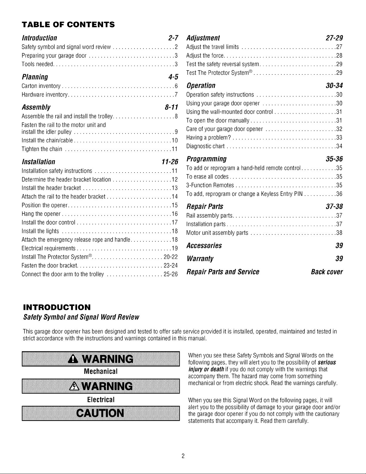
TABLE OF CONTENTS
Introduction 2-7
Safety symbol and signal word review ..................... 2
Preparingyour garagedoor ............................. 3
Tools needed......................................... 3
Planning 4-5
Carton inventory ...................................... 6
Hardware inventory.................................... 7
Assembly 8-11
Assemble the rail and install the trolley ..................... 8
Fastenthe rail to the motor unit and
install the idler pulley .................................. 9
Install the chain/cable ................................. 10
Tighten the chain .................................... 11
Installation 11-26
Installation safety instructions .......................... 11
Determine the headerbracket location .................... 12
Install the header bracket .............................. 13
Attach the rail to the headerbracket ...................... 14
Position the opener................................... 15
Hang the opener ..................................... 16
Install the door control ................................ 17
Install the lights ..................................... 18
Attach the emergency releaseropeand handle.............. 18
Electrical requirements ................................ 19
Install The Protector System®........................ 20-22
Fastenthe door bracket............................. 23-24
Connect the door arm to the trolley ................... 25-26
Adjustment 27-29
Adjust the travel limits ................................ 27
Adjust the force...................................... 28
Test the safety reversal system.......................... 29
Test The Protector System® ............................ 29
Operation 30-34
Operationsafety instructions ........................... 30
Usingyour garage door opener ......................... 30
Usingthe wall-mounted door control ..................... 31
To open the door manually............................. 31
Careof your garagedoor opener ........................ 32
Havinga problem? ................................... 33
Diagnosticchart ..................................... 34
Programming 35-36
To add or reprogram a hand-held remote control ............ 35
To erase all codes.................................... 35
3-Function Remotes.................................. 35
To add, reprogram or change a KeylessEntry PIN ........... 36
Repair Parts 37-38
Rail assembly parts................................... 37
Installation parts ..................................... 37
Motor unit assembly parts ............................. 38
Accessories 39
Warranty
Repair Partsand Service
39
Back cover
INTRODUCTION
SafetySymboland Signal WordReview
This garage door opener has beendesigned and tested to offer safe service provided it is installed, operated, maintained and tested in
strict accordancewith the instructions and warnings contained in this manual.
Mechanical
Electrical
When you seethese Safety Symbols and Signal Words on the
following pages,they will alert you to the possibility of serious
injury or deathif you do not comply with the warnings that
accompanythem. The hazard may come from something
mechanicalor from electric shock. Readthe warnings carefully.
When you seethis SignalWord on the following pages, it will
alert you to the possibility of damageto your garagedoor and/or
the garage door opener if you do not comply with the cautionary
statementsthat accompany it. Readthem carefully.
Preparingyourgaragedoor
Beforeyou begin:
• Disablelocks.
• Removeany ropes connected to garagedoor.
• Completethe followingtestto make sure your garagedoor is
balanced and is not sticking or binding:
1. Lift the door about halfway as shown. Releasethe door.
If balanced, it should stay in place,supported entirely by its
springs.
2. Raiseand lower the door to see if there is any binding or
sticking.
If your door binds, sticks, or is out of balance,call a trained door
systems technician.
To prevent possible SERIOUSINJURYor DEATH:
• ALWAYScall a trained door systems technician if garage door
binds, sticks, or is out of balance.An unbalanced garagedoor
may NOTreverse when required.
• NEVERtry to loosen, move or adjust garagedoor, door
springs, cables, pulleys, brackets or their hardware, ALL of
which are under EXTREMEtension.
• Disable ALL locks and removeALL ropes connected to garage
door BEFOREinstalling and operating garage door opener to
avoid entanglement.
To preventdamage to garage door and opener:
• ALWAYSdisable locks BEFOREinstalling and operating the
opener.
• ONLYoperate garage door opener at 120V, 60 Hzto avoid
malfunction and damage.
SectionalDoor
One-Piece Door
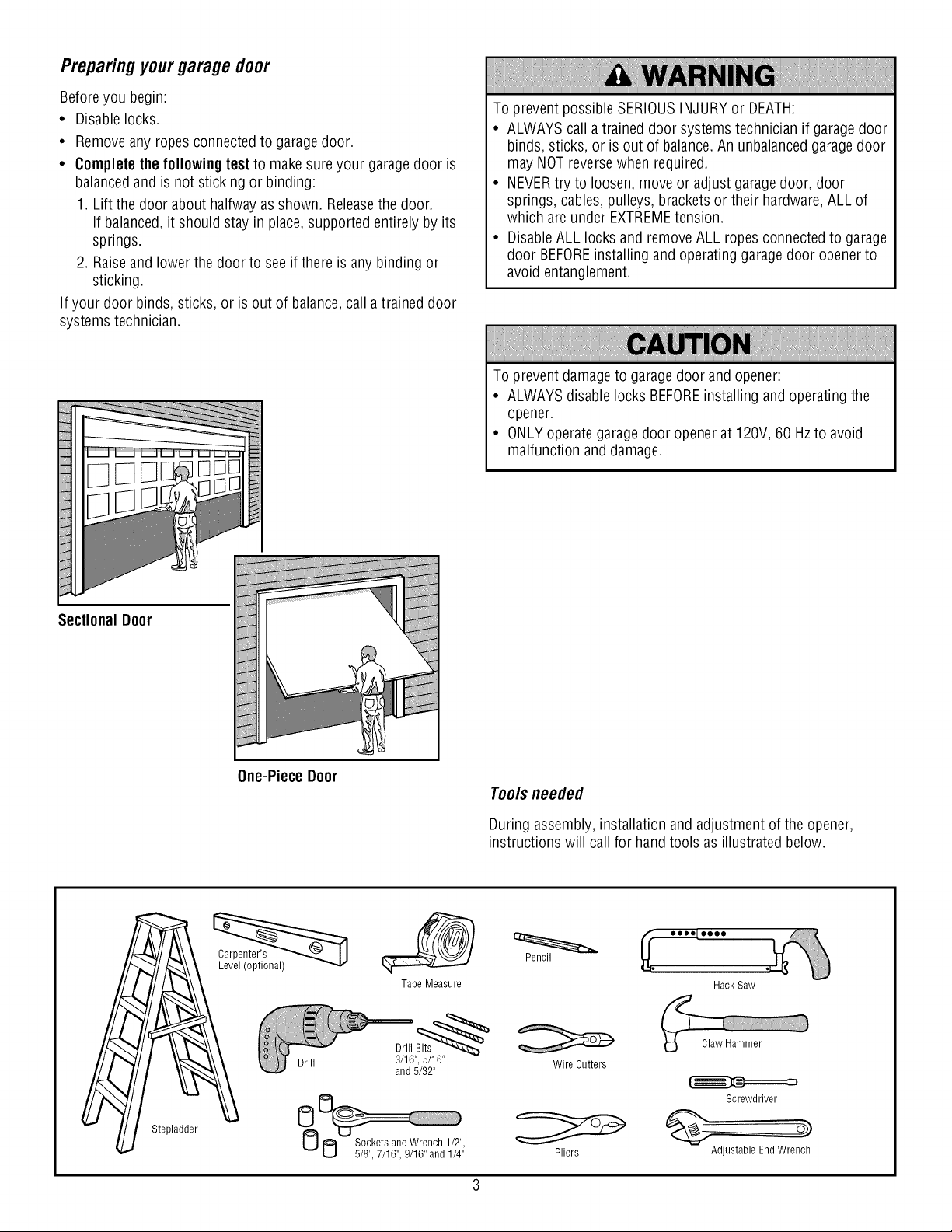
Tools needed
During assembly, installation and adjustment of the opener,
instructions will call for hand tools as illustrated below.
Stepladder
Tape Measure
Drill
Drill Bits_
3/16", 5/16"
and 5/32"
0
Pencil
Wire Cutters
Pliers
Hack Saw
Claw Hammer
Screwdriver
Adjustable EndWrench
P_nnmg
Identify the type and height of your garagedoor. Survey your
garagearea to see if any of the conditions below apply to your
installation. Additional materials may be required. You mayfind it
helpful to refer back to this pageand the accompanying
illustrations as you proceed with the installation of your opener.
Dependingon your requirements, there areseveral installation
steps which may call for materials or hardware not included in the
carton.
• Installation Step 1- Look at the wall or ceiling abovethe garage
door. The header bracket must be securely fastenedto
structural supports.
• Installation Step 5- Do you have a finished ceiling in your
garage? If so, a support bracket and additional fastening
hardware may be required.
• Installation Step 10- Dependingupon garageconstruction,
extension bracketsor wood blocks may be neededto install
sensors.
• Installation Step 10 - Alternate floor mounting of the safety
reversing sensorwill require hardware not provided.
Do you havean accessdoor in addition to the garagedoor?
If not, Model 53702 Emergency Key Releaseis required. See
Accessories page.
Look at the garagedoor where it meets the floor. Any gap
betweenthe floor and the bottom of the door must not exceed
1/4" (6 mm). Otherwise,the safety reversalsystem may not
work properly. SeeAdjustment Step 3. Floor or door should be
repaired.
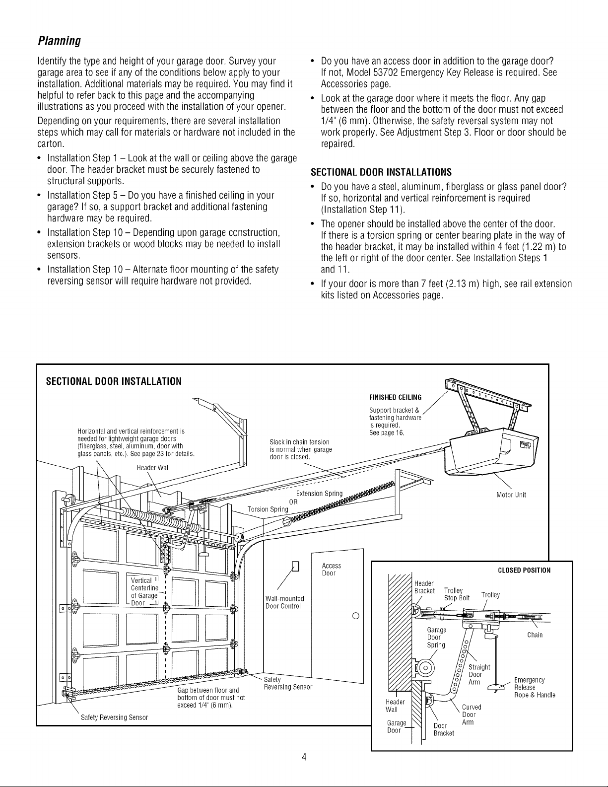
SECTIONALDOORINSTALLATIONS
• Do you havea steel, aluminum, fiberglass or glass paneldoor?
If so, horizontal andvertical reinforcement is required
(Installation Step 11).
• The openershould be installed abovethe center of the door.
If there is a torsion spring or center bearing plate in the way of
the headerbracket, it may be installed within 4 feet (1.22 m) to
the left or right of the door center. SeeInstallation Steps 1
and 11.
• If your door is more than 7 feet (2.13 m) high, see rail extension
kits listed on Accessories page.
SECTIONALDOORINSTALLATION
Horizontal and vertical reinforcement is
needed for lightweight garage doors
(fiberglass, steel, aluminum, door with
glass panels, etc.). See page 23 for details.
HeaderWall
Slack in chain tension
is normal when garage
door is closed.
FINISHED CEILING
Support bracket &
fastening hardware
is required.
See page 16.
Extension Spring
OR
Torsion Spring
Motor Unit
Centerline
of Garage_
Door _z_
Wall-mounted
Door Control
Safety Reversing Sensor
Gapbetween floor and
bottom of door must not
exceed 1/4" (6 mm).
Safety
Reversing Sensor
Access
Door
O
i
CLOSEDPOSITION
Header
Bracket Trolle
Garage
Door- /_/ E_ unam
I
ht_
_J Arm | j Emergency
,_o°j/ _ .... _ ReleaSe..
__ Rope&Handle
\_1 P_ \ Curved
HI \ ' Door
__1 I_oor Arm
ij Bracket
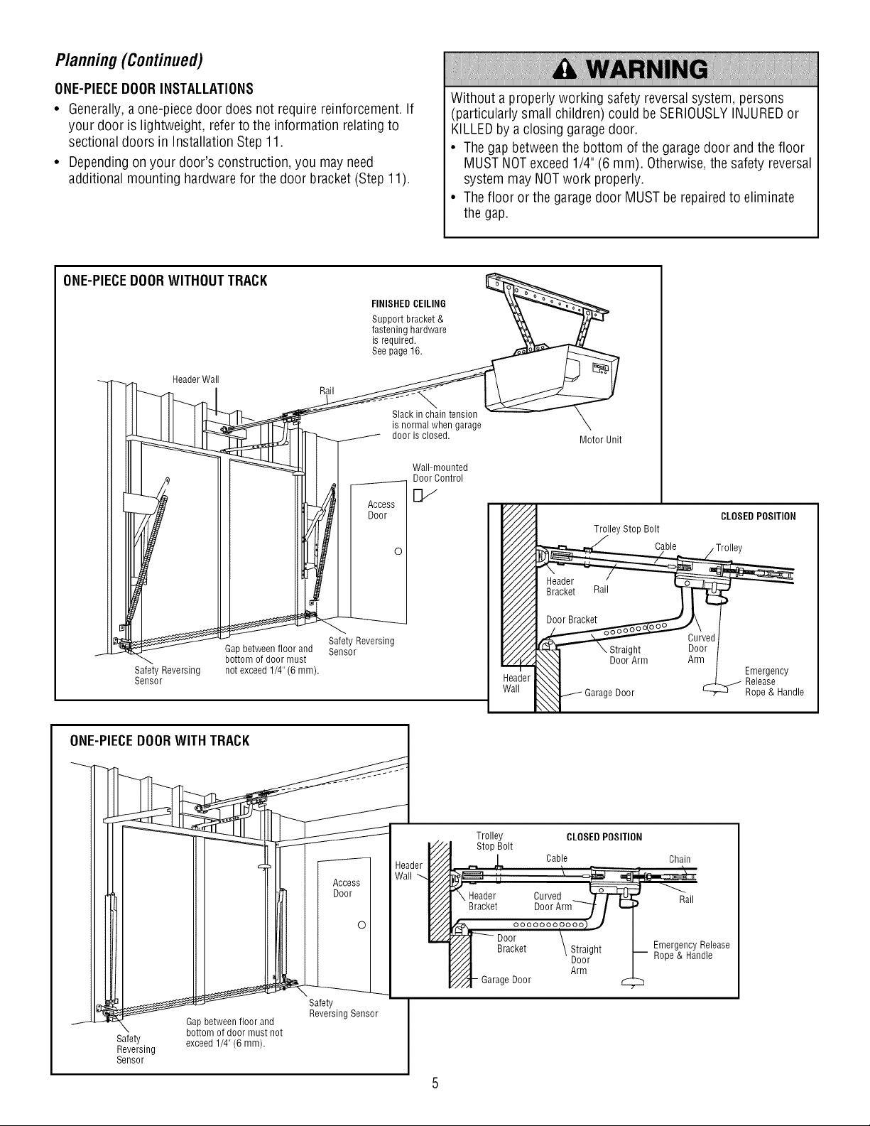
Planning(Continued)
ONE-PIECEDOORINSTALLATIONS
• Generally,a one-piece door does not require reinforcement. If
your door is lightweight, refer to the information relating to
sectional doors in Installation Step 11.
• Dependingon your door's construction, you may need
additional mounting hardwarefor the door bracket (Step 11).
Without a properly working safety reversalsystem, persons
(particularly small children) could be SERIOUSLYINJUREDor
KILLEDby a closing garagedoor.
• The gap between the bottom of the garage door and the floor
MUST NOTexceed 1/4" (6 mm). Otherwise,the safety reversal
system may NOTwork properly.
• The floor or the garagedoor MUST be repairedto eliminate
the gap.
ONE-PIECEDOORWITHOUTTRACK
EINIS,EDCEILINO '&__
Support bracket & _
fastening hardware _
is required. _
See page 16. _ _.,_,_,_r /_,
_ Header Wall //I \ _ II
II1Ill I _ is_i_l_i_e;si_; e X
_ _ [_ ............. Motorunit
IIII o I _11 I _ _Wo1';_°_tnrtold
_ I II_iII I _oor I_ CLOSEDPOS,T,O.
IIIdl_ I Ill'Ill I I V/./_I T_,,eystopBo,t
• I IIIII_l I I o I V/./ _ Cab,e Tro,,oy
oii,m!!!!
Sensor le
I __ Safety. I
._J. _ 14_ GoatPtbetoWfe_nH f'^..oor°l_lru_dnot Reversing Sensor I
SaefveertYing exceed 1/4" (6 mnl). I
Sensor J
5
Trolley
Stop Bolt
_,, Cab!e L
_eader Curved_ W_
Bracket D00rArm7 / i._
_ ooooooooooo_J
p_- Door \
//_.._ Bracket \ Straight
////_ Door
//".-! Arm
Y_'/-_-Garage Door
CLOSED POSITION
Chain
) Rail
EmergencyRelease
-- Rope & Handle
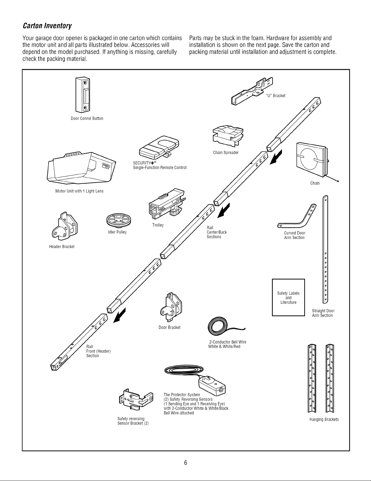
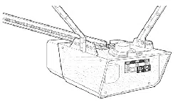
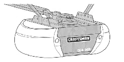
CartonInventory
Your garage door opener is packagedin one carton which contains
the motor unit and all parts illustrated below. Accessories will
dependon the model purchased. If anything is missing, carefully
check the packing material.
Parts may be stuck in the foam. Hardwarefor assembly and
installation is shown on the next page.Savethe carton and
packing material until installation and adjustment is complete.
Door Conrol Button
Motor Unit with 1 Light Lens
Header Bracket
Idler Pulley
Rail
Front (Header)
Section
SECURITY÷ ®
Single-Function Remote Control
Trolley
Door Bracket
Safety reversing
Sensor Bracket (2)
Chain Spreader
Rail
Center/Back
Sections
2-Conductor Bell Wire
White & White/Red
The Protector Systerr_ _
(2) Safety Reversing Sensors
(1 Sending Eyeand 1 Receiving Eye)
with 2-Conductor White & White/Black
Bell Wire attached
Chain
Curved Door
Arm Section
Safety Labels
and
Literature
_'1
J
Straight Door
Arm Section
I,
1,
%
I.
%
_1°
Hanging Brackets
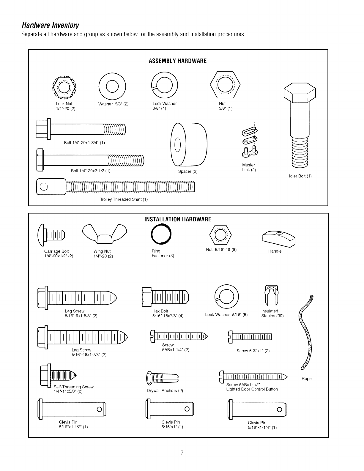
HardwareInventory
Separateall hardware and group as shown below for the assembly and installation procedures.
ASSEMBLYHARDWARE
Lock Nut Washer 5/8" (2) Lock Washer Nut
1/4"-20 (2) 3/8" (1) 3/8" (1)
0
[o
Bolt 1/4"-20xl-3/4" (1)
)lii;)l)))i!))l!_)
Bolt 1/4"-20x2-1/2 (1)
Trolley Threaded Shaft (1)
Spacer (2)
1
i
Master
Link (2)
Idler Bolt(l)
Carriage Bolt
1/4"-20xl/2" (2)
Wing Nut
1/4"-20 (2)
INSTALLATIONHARDWARE
© %
Ring Nut 5/16"-18 (6)
Fastener (3)
Handle
Lag Screw
5/16"-9xl-5/8" (2)
111111111111_>
Lag Screw
5/16"-18xl-7/8" (2)
_ng Screw
1/4"-14x5/8" (2)
_llllllllll) _:_
Hex Bolt
5/16"-18x7/8" (4) Lock Washer 5/16" (5)
_lllllllllllllllllllllllll}
Screw
6ABx1-1/4" (2)
iiii_;i -h
III/HI
Drywall Anchors (2)
Insulated
Staples (30)
111111111111111111111
Screw 6-32xl" (2)
_ ifiii-fiiiiNfiiifii]iiiiii fiii';:>
Screw 6ABxl-1/2"
Lighted Door Control Button
ol
Clevis Pin Clevis Pin Clevis Pin
5/16"x1-1/2" (1) 5/16"x1" (1) 5/16"x1-1/4" (1)
Rope
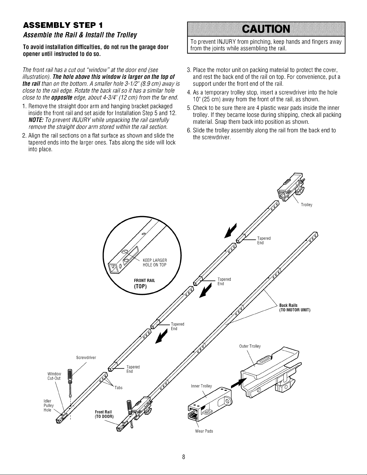
ASSEMBLY STEP 1
Assemble the Rail & Install the Trolley
To avoid installationdifficulties, do notrun the garagedoor
openeruntil instructedto do so.
To prevent INJURYfrom pinching, keep hands and fingers away
from the joints while assembling the rail.
Thefront raft has a cut out "window" at the door end (see
illustration). The hole abovethis windowis larger on the topof
the rail than on the bottom. A smaller hole 3-1/2" (8.9 cm) away is
close to the rail edge. Rotate the back rail so it has a similar hole
close to the oppositeedge,about 4-3/4" (12 cm) from the far end.
1. Removethe straight door arm and hanging bracket packaged
inside the front rail and set aside for Installation Step 5 and 12.
NOTE:Toprevent INJURY while unpacking the rail carefully
removethe straight door arm stored within the rail section.
2. Align the rail sections on aflat surface as shown and slide the
tapered ends into the larger ones.Tabs along the side will lock
into place.
3. Placethe motor unit on packing materialto protect the cover,
and rest the back endof the rail on top. For convenience, put a
support under the front end of the rail.
4. As a temporary trolley stop, insert a screwdriver into the hole
10" (25 cm) awayfrom the front of the rail, as shown.
5. Checkto besure there are4 plastic wear pads inside the inner
trolley. If they became loose during shipping, check all packing
material. Snap them back into position as shown.
6. Slidethe trolley assembly along the rail from the backend to
the screwdriver.
Trolley
)ered
End
Screwdriver
Window
Cut-Out
Idler
Pulley
Hole
FrontRail
(TO DOOR)
Tapered
End
)ered
End
Tapered
End
BackRails
(TO MOTORUNIT)
Outer Trolley
Inner Trolley __
Wear Pads
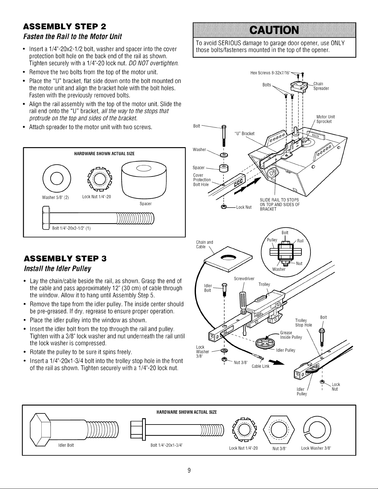
ASSEMBLY STEP 2
Fastenthe Rail to the Motor Unit
• Insert a 1/4"-20x2-1/2 bolt, washer and spacer into the cover
protection bolt hole on the backend of the rail as shown.
Tighten securely with a 1/4"-20 lock nut. DO NOToverfighten.
• Removethe two bolts from the top of the motor unit.
• Placethe "U" bracket,flat side down onto the bolt mounted on
the motor unit and align the bracket hole with the bolt holes.
Fastenwith the previously removed bolts.
• Align the rail assemblywith the top of the motor unit. Slide the
rail end onto the "U" bracket, all the way to the stops that
protrude on the top and sides of the bracket.
• Attach spreader to the motor unit with two screws.
Washer 5/8" (2)
HARDWARESHOWN ACTUALSIZE
o@
LockNut1/4"-20
Spacer
Bolt 1/4"-20x2-1/2" (1)
ASSEMBLY STEP 3
Installthe Idler Pulley
• Laythe chain/cable beside the rail, as shown. Graspthe end of
the cable and pass approximately 12" (30 cm) of cable through
the window. Allow it to hang until Assembly Step 5.
• Removethe tape from the idler pulley. The inside center should
be pre-greased. If dry, regreaseto ensure proper operation.
• Placethe idler pulley into the window as shown.
• Insert the idler bolt from the top through the rail and pulley.
Tighten with a 3/8" lock washer and nut underneaththe rail until
the lock washer is compressed.
• Rotatethe pulley to be sure it spins freely.
• Insert a 1/4"-20xl-3/4 bolt into the trolley stop hole in the front
of the rail as shown. Tighten securely with a 1/4"-20 lock nut.
To avoid SERIOUSdamageto garagedoor opener, use ONLY
those bolts/fasteners mounted in the top of the opener.
Hex Screws 8-32x7/16"_,
Bolts_ _ _L_Ohain
-____. [::_:._ Spreader
I
Bolt ___
Washer_
i
Spacer_
Cover
Protection
Bolt Hole
"U" Bracket
Motor Unit
Sprocket
SLIDE RAIL TOSTOPS
ON TOP AND SIDES OF
1_ Lock Nut BRACKET
Chain and
Cable
Washer
Screwdriver
Trolley
Trolley
Stop Hole
Grease
_ _ _ _ -Inside Pulley
WasherL°Ck_ _ Idler Pulley
3/8" _, Nut 3/8"
Cable Link
Idler
Pulley
Bolt
Idler Bolt
HARDWARESHOWN ACTUALSIZE
Bolt 1/4"-20xl-3/4"
@
Lock Nut 1/4"-20
Nut 3/8"
Lock Washer 3/8"
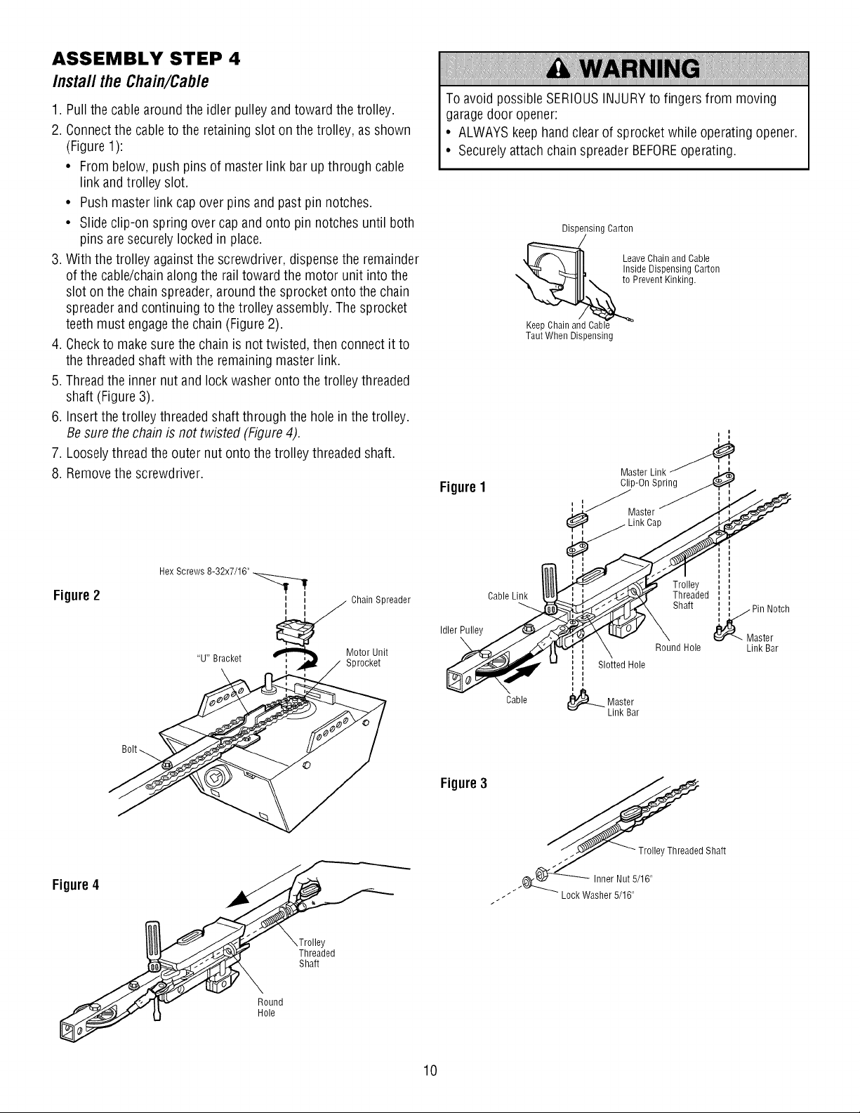
ASSEMBLY STEP 4
Install the Chain/Cable
1. Pull the cable around the idler pulley and toward the trolley.
2. Connectthe cable to the retaining slot on the trolley, as shown
(Figure 1):
• From below, push pins of master link bar up through cable
link and trolley slot.
• Push master link cap over pins and past pin notches.
• Slide clip-on spring over cap and onto pin notches until both
pins aresecurely locked in place.
3. With the trolley against the screwdriver, dispensethe remainder
of the cable/chain along the rail toward the motor unit into the
slot on the chain spreader, around the sprocket onto the chain
spreader and continuing to the trolley assembly. The sprocket
teeth must engagethe chain (Figure 2).
4. Checkto makesure the chain is not twisted, then connect it to
the threaded shaft with the remaining master link.
5. Threadthe inner nut and lock washer onto the trolley threaded
shaft (Figure 3).
6. Insert the trolley threadedshaft through the hole in the trolley.
Be sure the chain is not twisted (Figure 4).
7. Looselythread the outer nut onto the trolley threaded shaft.
8. Removethe screwdriver.
Figure2
Hex Screws 8-32x7/16"
Chain Spreader
Motor Unit
Sprocket
To avoid possible SERIOUSINJURYto fingers from moving
garagedoor opener:
• ALWAYS keephand clear of sprocket while operating opener.
• Securely attach chain spreader BEFOREoperating.
Dispensing Carton
:_ Leave Chain and Cable
Inside Dispensing Carton
t_Cabl_e to Prevent Kinking.
Taut When Dispensing
FigureI
®
I
Cable Link__.
Cable
Master Link
Clip-On Spring
astor
II
/ II t
/_ Threaded : ',
Shaft _ Pin Notch
•" \ _ \ Er'---- Master
\ Round Hole Link Bar
', Slotted Hole
i
(_)-_ Master
Link Bar
Figure4
Figure 3
J
----- Lock Washer 5/16"
t
/
Y
Threaded
Shaft
Round
Hole
10
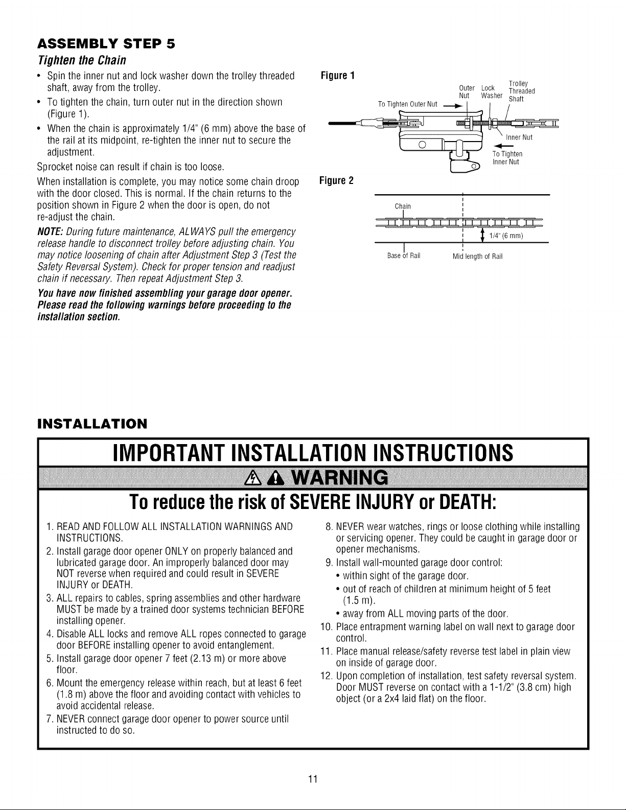
ASSEMBLY STEP 5
Tightenthe Chain
• Spin the innernut and lockwasher down the trolley threaded
shaft, awayfrom the trolley.
• To tighten the chain, turn outer nut in the direction shown
(Figure 1).
• When the chain is approximately 1/4" (6 mm) above the base of
the rail at its midpoint, re-tighten the inner nut to secure the
adjustment.
Sprocket noise can result if chain is too loose.
When installation is complete, you may notice some chain droop
with the door closed. This is normal. If the chain returns to the
position shown in Figure 2 when the door is open, do not
re-adjust the chain.
NOTE:During future maintenance,ALWAYS puff the emergency
release handle to disconnect trofley before adjusting chain. You
may notice loosening of chain after Adjustment Step 3 (Test the
Safety ReversalSystem). Check for proper tension and readjust
chain if necessary. ThenrepeatAdjustment Step 3.
Youhave nowfinished assemblingyour garage door opener.
Please read the following warningsbeforeproceedingto the
installation section.
Figure1
Figure 2
Trolley
Outer Lock Threaded
Nut Washer Shaft
To Tighten Outer Nut
Inner Nut
To Tighten
Inner Nut
I
Chain
Base Rail
1/4" (6 mm)
Mid length of Rail
INSTALLATION
IMPORTANTINSTALLATIONINSTRUCTIONS
ToreducetheriskofSEVEREINJURYorDEATH:
1. READAND FOLLOWALL INSTALLATIONWARNINGSAND
INSTRUCTIONS.
2. Install garage door openerONLYon properly balanced and
lubricated garage door. An improperly balanceddoor may
NOTreverse when required and could result in SEVERE
INJURYor DEATH.
3. ALL repairs to cables, spring assembliesand other hardware
MUST be made by a trained door systems technician BEFORE
installing opener.
4. DisableALL locks and remove ALL ropes connected to garage
door BEFOREinstalling opener to avoid entanglement.
5. Install garagedoor opener7 feet (2.13 m) or more above
floor.
6. Mount the emergency releasewithin reach, but at least 6 feet
(1.8 m) above the floor and avoiding contact with vehicles to
avoid accidental release.
7. NEVERconnect garagedoor openerto power source until
instructed to do so.
8. NEVERwear watches, rings or loose clothing while installing
or servicing opener. They could be caught in garagedoor or
opener mechanisms.
9. Install wall-mounted garage door control:
• within sight of the garage door.
• out of reach of children at minimum height of 5 feet
(1.5 m).
• awayfrom ALL moving parts of the door.
10. Placeentrapment warning labelon wall next to garage door
control.
11. Placemanual release/safetyreversetest label in plain view
on inside of garagedoor.
12. Upon completion of installation, test safety reversalsystem.
Door MUST reverseon contact with a 1-1/2" (3.8 cm) high
object (or a 2x4 laid flat) on the floor.
11
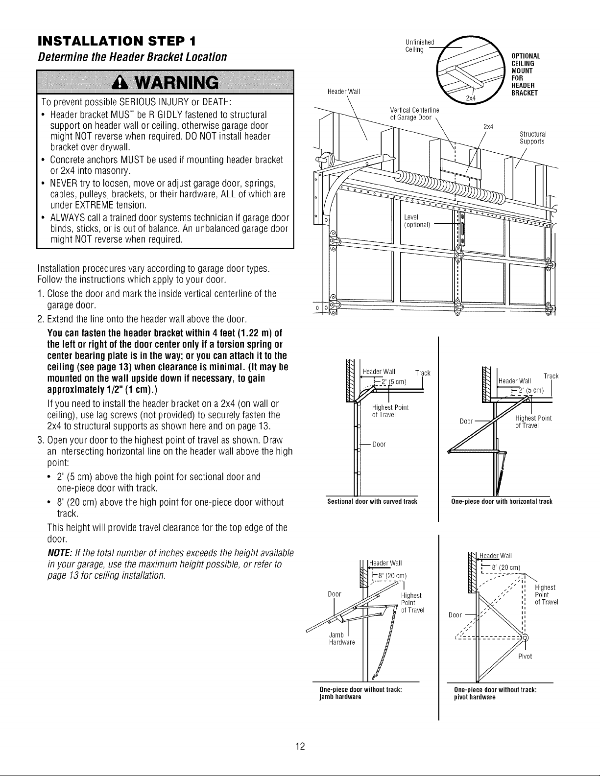
INSTALLATION STEP 1
Determinethe Header BracketLocation
To prevent possible SERIOUSINJURYor DEATH:
• Header bracket MUST be RIGIDLYfastened to structural
support on headerwall or ceiling, otherwise garagedoor
might NOTreversewhen required. DO NOTinstall header
bracket over drywall.
• Concrete anchors MUST be used if mounting headerbracket
or 2x4 into masonry.
• NEVERtry to loosen, move or adjust garagedoor, springs,
cables, pulleys, brackets, or their hardware, ALL of which are
under EXTREMEtension.
• ALWAYScall a trained door systems technician if garage door
binds, sticks, or is out of balance.An unbalancedgarage door
might NOTreversewhen required.
Header Wall
Unifliinnghe_
Vertical Centerline
of Garage Door
2x4
OPTIONAL
CEILING
MOUNT
FOR
HEADER
BRACKET
Structural
Suppo_s
Installation procedures vary according to garagedoor types.
Follow the instructions which apply to your door.
1. Closethe door and mark the inside vertical centerline of the
garagedoor.
2. Extendthe line onto the headerwall abovethe door.
Youcan fastenthe header bracketwithin4 feet (1.22 m) of
the left or rightof the door centeronly if a torsionspringor
centerbearing plate is in the way;or you can attach it to the
ceiling (see page 13) whenclearance is minimal. (It may be
mountedonthe wall upsidedown if necessary,to gain
approximately1/2" (1 cm).)
If you needto install the header bracket on a 2x4 (on wall or
ceiling), use lag screws (not provided) to securely fasten the
2x4 to structural supports as shown here and on page 13.
3. Openyour door to the highest point of travel as shown. Draw
an intersecting horizontal line on the headerwall abovethe high
point:
• 2" (5 cm) abovethe high point for sectional door and
one-piece door with track.
• 8" (20 cm) abovethe high point for one-piece door without
track.
This height will provide travel clearancefor the top edge of the
door.
NOTE:If the total number of inches exceedsthe height available
in your garage, use the maximum height possible, or refer to
page 13for ceiling installation.
HeaderWall Track
_2_" (.5cm)
<,[ i
HighestPoint
of Travel
--Door
Sectional door with curved track
Hardware
HeaderWall
-8" (20 cm)
Highest
Point
of Travel
One-piecedoorwithouttrack:
jambhardware
Y
Track
HeaderWall
"_',_ 2" (5 cm)
_et Point
of Travel
r
One-piece doorwith horizontal track
Header Wall
Pivot
One-piece door without track:
pivot hardware
12
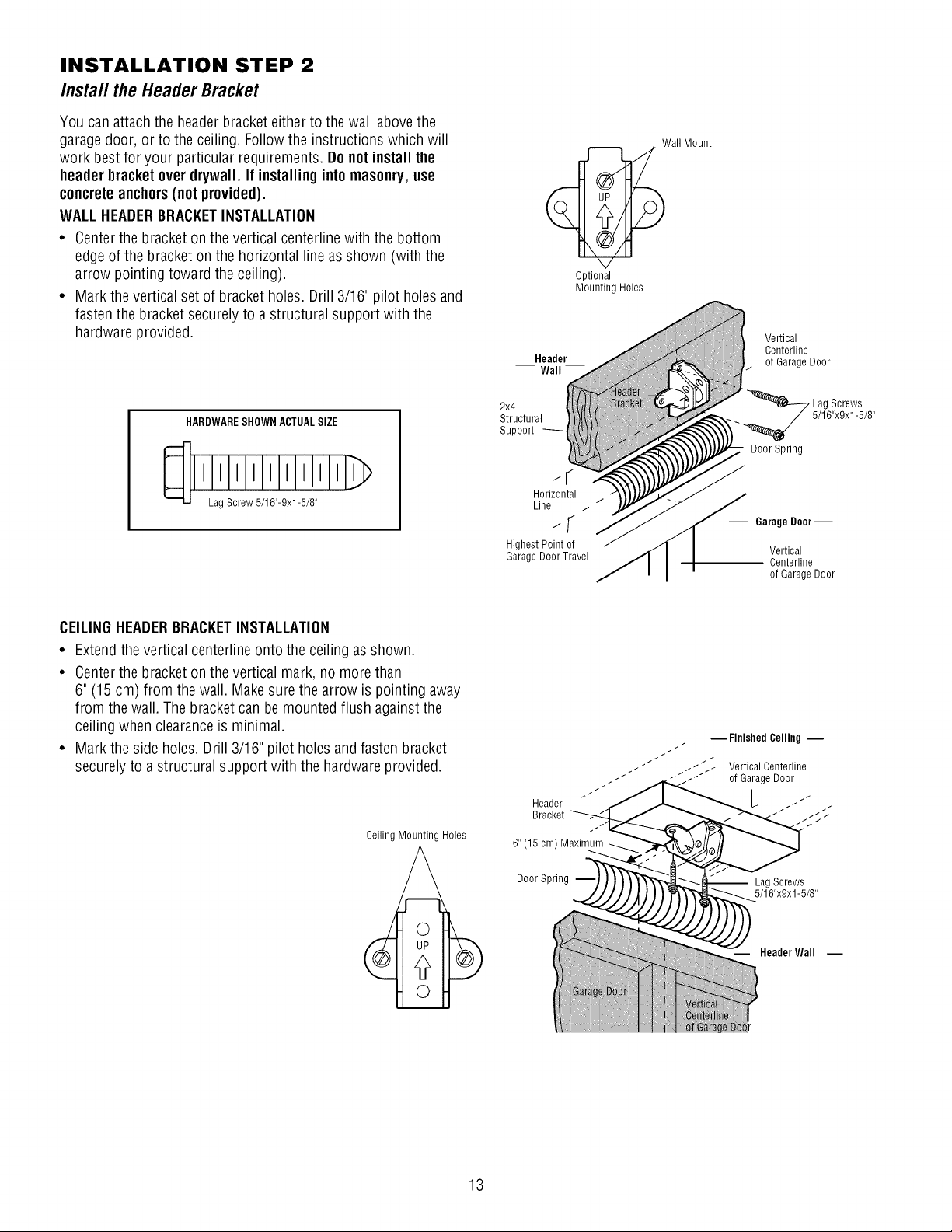
INSTALLATION STEP 2
Installthe HeaderBracket
You can attach the headerbracket either to the wall above the
garagedoor, or to the ceiling. Follow the instructions which will
work best for your particular requirements. Do not install the
header bracketoverdrywall. If installing into masonry,use
concreteanchors(not provided),
WALLHEADERBRACKETINSTALLATION
• Centerthe bracket on the vertical centerline with the bottom
edge of the bracket on the horizontal line as shown (with the
arrow pointing toward the ceiling).
• Mark the vertical set of bracket holes. Drill 3/16" pilot holes and
fasten the bracket securely to a structural support with the
hardware provided.
HARDWARESHOWN ACTUALSIZE
Lag Screw 5/16"-9xl-5/8"
Wall Mount
Optional
MountingHoles
Horizontal
Line / /
-; S
Highest Point of
Garage DoorTravel
Vertical
Centerline
of Garage Door
Lag Screws
. 5/16"x9x1-5/8"
Door Spring
-- Garage Door--
Vertical
Centerline
of Garage Door
CEILINGHEADERBRACKETINSTALLATION
• Extendthe vertical centerline onto the ceiling as shown.
• Centerthe bracket on the vertical mark, no more than
6" (15 cm) from the wall. Makesure the arrow is pointing away
from the wall. The bracket can be mounted flush against the
ceiling when clearanceis minimal.
• Mark the side holes. Drill 3/16" pilot holes and fasten bracket
securely to a structural support with the hardware provided.
Ceiling Mounting Holes
Header
Bracket
_Finished Ceiling m
_../_::_ Vertical Centerline
_ of Garage Door
6" (15 cm) Maximum
Door Spring
Lag Screws
5/16"x9x1-5/8"
Header Wall --
13
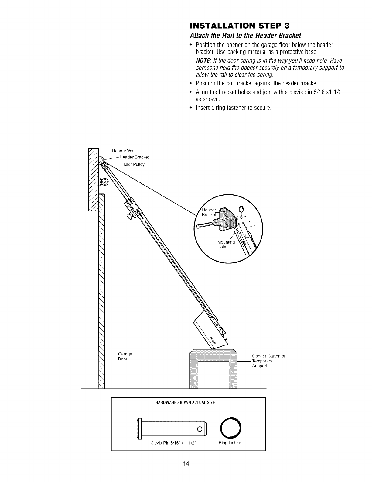
INSTALLATION STEP 3
Attach the Raft to the Header Bracket
• Position the opener on the garagefloor below the header
bracket. Usepacking material as a protective base.
NOTE:If the door spring is in the wayyou'll need help. Have
someone hold the opener securely on a temporary support to
allow the rail to clear the spring.
• Position the rail bracket againstthe header bracket.
• Align the bracket holes and join with a clevis pin 5/16"x1-1/2"
as shown.
• Insert a ring fastener to secure.
Wall
-- Idler Pulley
0
Mounting
Hole
-- Garage
Door
Opener Carton or
-- Temporary
Support
HARDWARESHOWN ACTUALSIZE
Clevis Pin 5/16" x 1-1/2"
©
Ring fastener
14
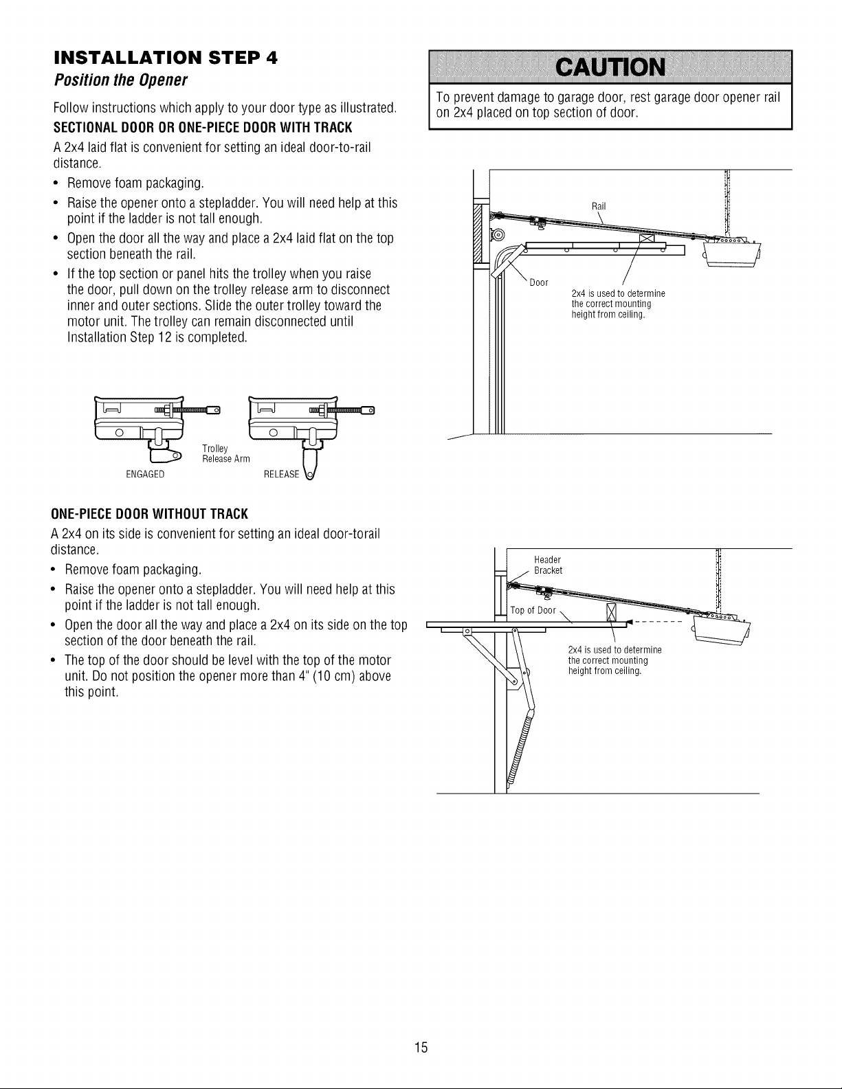
INSTALLATION STEP 4
Positionthe Opener
Follow instructions which apply to your door type as illustrated.
SECTIONALDOOROR ONE-PIECEDOORWITH TRACK
A 2x4 laid flat is convenient for setting an ideal door-to-rail
distance.
• Removefoam packaging.
• Raisethe openeronto astepladder. You will need help at this
point if the ladderis not tall enough.
• Openthe door all the way and place a 2x4 laidflat on the top
section beneaththe rail.
• If the top section or panel hits the trolley when you raise
the door, pull down on the trolley releasearm to disconnect
inner and outer sections. Slide the outer trolley toward the
motor unit. The trolley can remain disconnected until
Installation Step 12 is completed.
To preventdamage to garagedoor, rest garage door opener rail
on 2x4 placedon top section of door.
Rail
2x4 is used to determine
the correct mounting
height from ceiling.
y }-=€'
seArm [J
ENGAGED RELEASE V
ONE-PIECEDOORWITHOUTTRACK
A 2x4 on its side is convenient for setting an ideal door-torail
distance.
• Removefoam packaging.
• Raisethe opener onto a stepladder.You will needhelp at this
point if the ladder is not tall enough.
• Openthe door all the way and placea 2x4 on its side on the top
section of the door beneaththe rail.
• Thetop of the door should be level with the top of the motor
unit. Do not position the opener more than 4" (10 cm) above
this point.
I 1 Header
; 4, used!o2rm, e
i _hegh_r_2,tlln___nnt;n,g
15
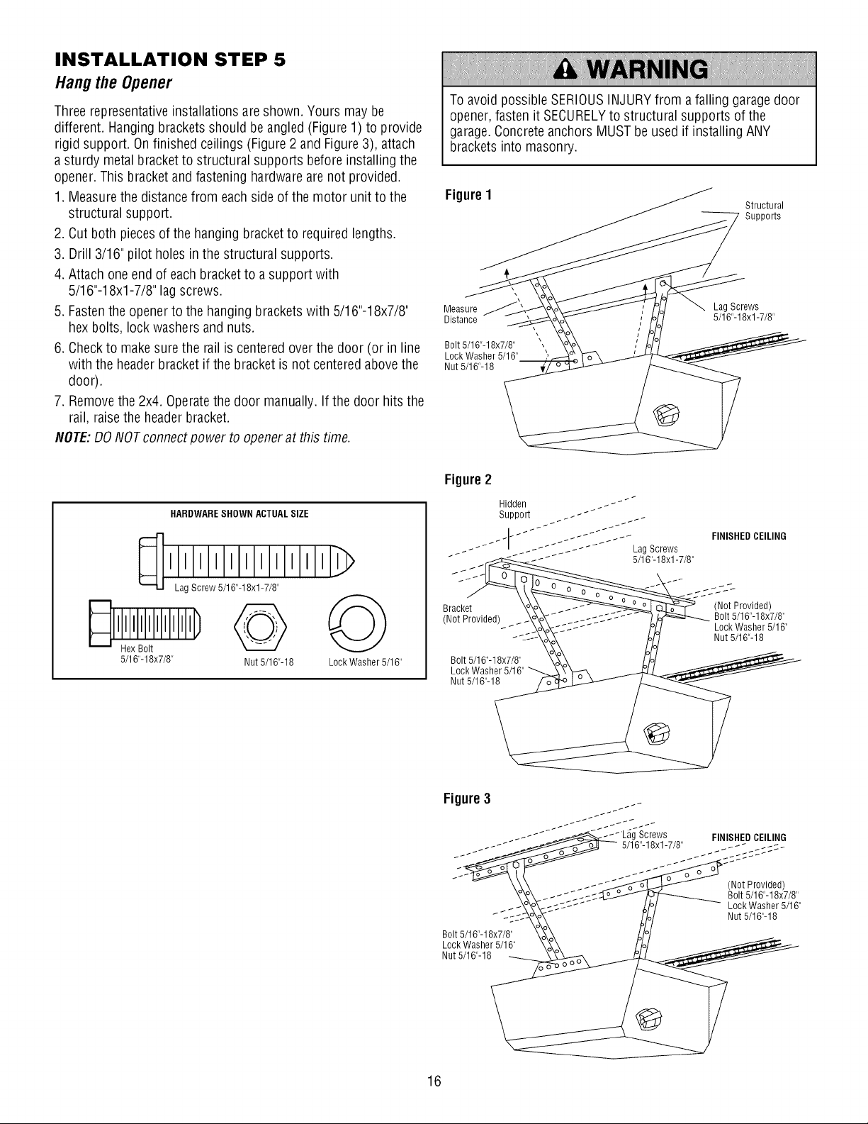
INSTALLATION STEP 5
Hangthe Opener
Three representativeinstallations areshown. Yours may be
different. Hanging bracketsshould be angled (Figure 1) to provide
rigid support. On finished ceilings (Figure 2 and Figure3), attach
a sturdy metal bracket to structural supports before installing the
opener. This bracket and fastening hardware are not provided.
1. Measurethe distance from each side of the motor unit to the
structural support.
2. Cut both piecesof the hanging bracket to required lengths.
3. Drill 3/16" pilot holes in the structural supports.
4. Attach one end of each bracket to a support with
5/16"-18xl-7/8" lagscrews.
5. Fastenthe openerto the hanging brackets with 5/16"-18x7/8"
hex bolts, lock washers and nuts.
6. Checkto makesure the rail is centered over the door (or in line
with the header bracket if the bracket is not centered above the
door).
7. Removethe 2x4. Operatethe door manually. If the door hits the
rail, raise the headerbracket.
NOTE:DO NOTconnect power to openerat this time.
To avoid possible SERIOUSINJURYfrom a falling garage door
opener, fasten it SECURELYto structural supports of the
garage.Concrete anchors MUST be used if installing ANY
brackets into masonry.
FigureI
Structural
Supports
Measure Lag Screws
Distance 5/16"-18xl -7/8"
Bolt 5/16"-18x7/8"
Lock Washer 5/16"
Nut 5/16"-18
\
HARDWARESHOWN ACTUALSIZE
Lag Screw 5/16"-18xl -7/8"
5/16"-18x7/8" Nut 5/16"-18 Lock Washer 5/16"
Figure 2
Hidden _ - _"""
Support _. - _"
_- Lag Screws
Bracket \o_o_ _- (Not Provided)
Not Provided/ _o_o_- _1-cc-J .... _/_ Bolt 5/16"-18x7/8"
- , _- __o_o_T-_ .... /oi,j Lock Washer 5/16"
J-=--_ Mo7 Nut 5/16"-18
Bolt 5/16'-18X7/8' _ o__/o/
Figure3
_'_- .-I Lag Screws FINISHED CEILING
-_ _" _ 5116"-18xl-7/8"
(Not Provided)
Bolt 5/16"-18x7/8"
Lock Washer 5/16"
Nut 5/16"-18
Bolt 5/16"-18x7/8"
Lock Washer 5/16"
Nut 5/16"-18
16
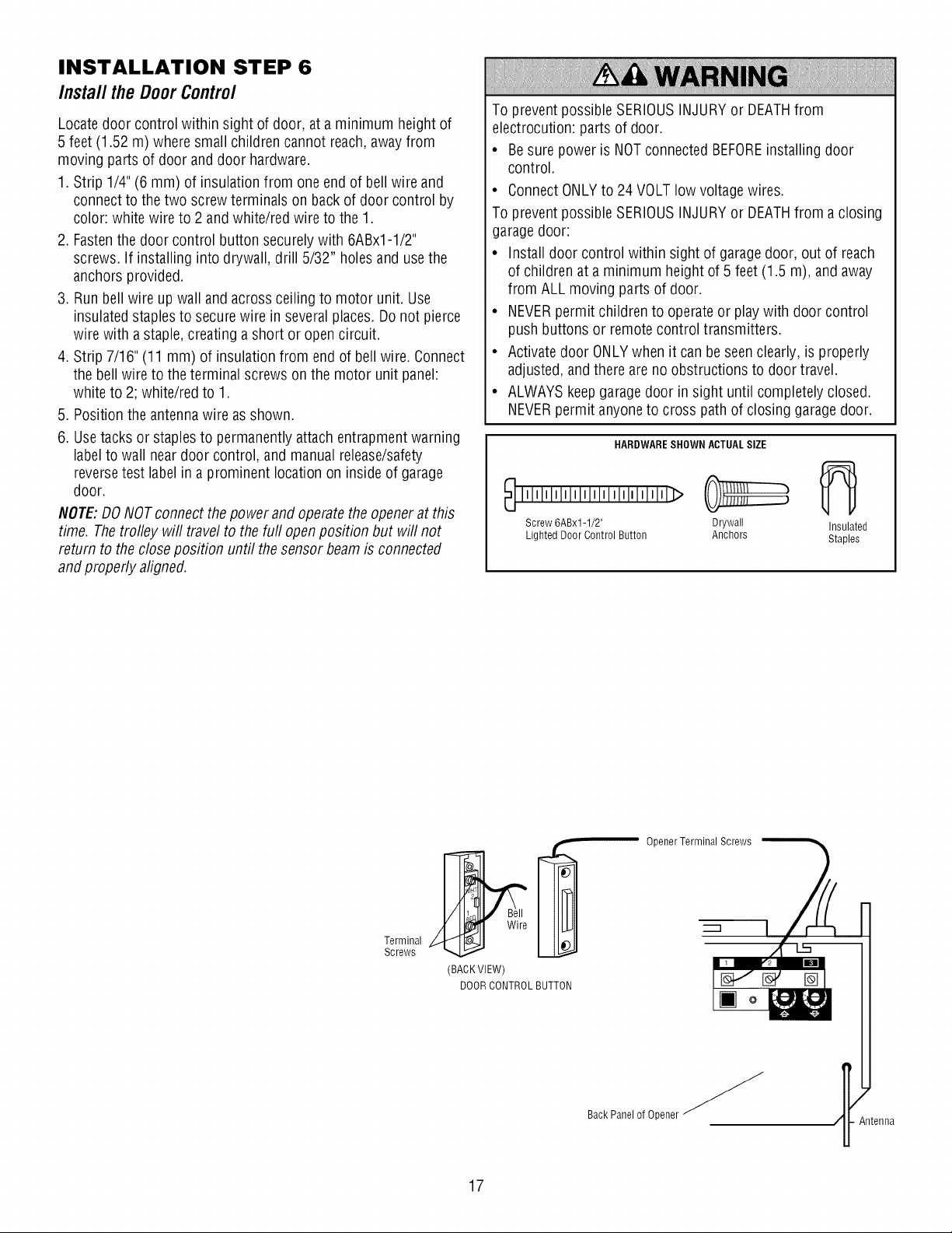
INSTALLATION STEP 6
Install the DoorControl
Locate door control within sight of door, at a minimum height of
5 feet (1.52 m) where small children cannot reach,away from
moving parts of door anddoor hardware.
1. Strip 1/4" (6 mm) of insulation from one end of bell wire and
connect to the two screw terminals on back of door control by
color: white wire to 2 and white/red wire to the 1.
2. Fastenthe door control button securely with 6ABx1-1/2"
screws. If installing into drywall, drill 5/32" holes and use the
anchors provided.
3. Run bell wire up wall and across ceiling to motor unit. Use
insulated staples to securewire in several places. Do not pierce
wire with a staple, creating a short or opencircuit.
4. Strip 7/16" (11 mm) of insulation from end of bell wire. Connect
the bell wire to the terminal screws on the motor unit panel:
white to 2; white/red to 1.
5. Position the antenna wire as shown.
6. Usetacks or staples to permanently attach entrapment warning
label to wall near door control, and manual release/safety
reversetest labelin a prominent location on inside of garage
door.
NOTE:DONOT connect the power and operatethe opener at this
time. The trolley will travel to the furl open position but will not
return to the closeposition until the sensor beam is connected
and properly aligned.
To prevent possible SERIOUSINJURYor DEATHfrom
electrocution: parts of door.
• Besure power is NOTconnected BEFOREinstalling door
control.
• ConnectONLYto 24 VOLT low voltagewires.
To prevent possible SERIOUSINJURYor DEATHfrom a closing
garage door:
• Install door control within sight of garage door, out of reach
of children at a minimum height of 5 feet (1.5 m), and away
from ALL moving parts of door.
• NEVERpermit children to operate or play with door control
push buttons or remote control transmitters.
• Activate door ONLYwhen it can be seenclearly, is properly
adjusted, andthere are no obstructions to door travel.
• ALWAYS keepgaragedoor in sight until completely closed.
NEVERpermit anyoneto cross path of closing garage door.
HARDWARESHOWN ACTUALSIZE
Screw 6ABx1-1/2" Drywall Insulated
Lighted Door Control Button Anchors Staples
Opener Terminal Screws
Terminal
Screws
(BACKVIEW)
DOORCONTROLBUTTON
BackPanel of Opener _
Antenna
17
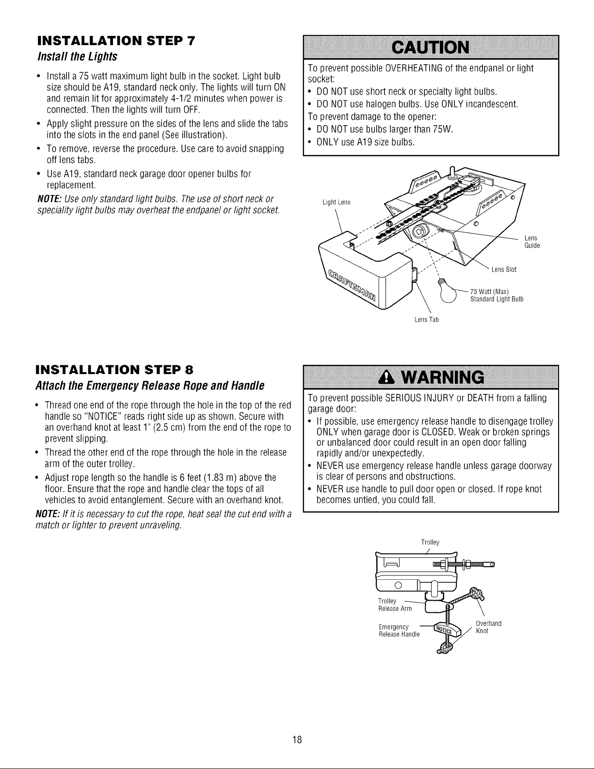
INSTALLATION STEP 7
Install the Lights
• Install a 75 watt maximum light bulb in the socket. Light bulb
size should beA19, standard neck only. The lights will turn ON
and remain lit for approximately 4-1/2 minutes when power is
connected.Then the lights will turn OFF.
• Apply slight pressure on the sides of the lens and slide the tabs
into the slots in the end panel (Seeillustration).
• To remove, reversethe procedure. Use careto avoid snapping
off lens tabs.
• UseA19, standard neck garage door opener bulbs for
replacement.
NOTE:Use only standard light bulbs. Theuse of short neck or
speciality light bulbs may overheat the endpanelor light socket.
To prevent possible OVERHEATINGof the endpanel or light
socket:
• DO NOT use short neck or specialty light bulbs.
• DO NOT use halogen bulbs. UseONLYincandescent.
To preventdamage to the opener:
• DO NOT use bulbs larger than 75W.
• ONLY useA19 sizebulbs.
Light Lens
Lens
Guide
Lens Slot
75 Watt (Max)
Standard Light Bulb
Lens Tab
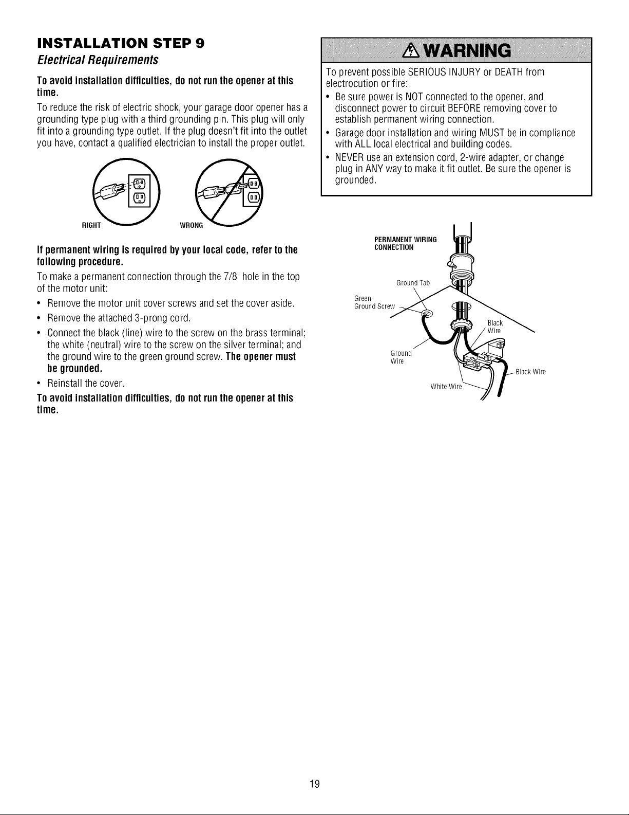
INSTALLATION STEP 8
Attachthe EmergencyRe/ease Ropeand Hand/e
• Thread one end of the rope through the holein the top of the red
handle so "NOTICE"reads right side up as shown. Secure with
an overhand knot at least 1" (2.5 cm) from the end of the rope to
prevent slipping.
• Threadthe other endof the rope through the hole in the release
arm of the outer trolley.
• Adjust rope length so the handle is 6 feet (1.83 m) above the
floor. Ensurethat the rope and handle clear the tops of all
vehicles to avoid entanglement.Secure with an overhand knot.
NOTE:If it is necessaryto cut the rope, heat seal the cut end with a
match or lighter to prevent unraveling.
To prevent possible SERIOUSINJURYor DEATHfrom afalling
garagedoor:
• If possible, use emergency releasehandle to disengagetrolley
ONLYwhen garagedoor is CLOSED.Weak or broken springs
or unbalanceddoor could result in an open door falling
rapidly and/or unexpectedly.
• NEVERuse emergency releasehandle unless garagedoorway
is clear of persons and obstructions.
• NEVERuse handleto pull door open or closed. If rope knot
becomes untied, you could fall.
Trolley
Emergency _ _ Overhand
Release Handle Knot
18
INSTALLATION STEP 9
Electrica/ Requirements
Toavoid installation difficulties,do notrun the openerat this
time.
To reducethe risk of electric shock, your garagedoor opener has a
grounding type plug with a third grounding pin. This plug will only
fit into a grounding type outlet. If the plug doesn't fit into the outlet
you have,contact a qualified electrician to install the proper outlet.
If permanent wiring is requiredby your local code, refer to the
followingprocedure.
To make a permanent connection through the 7/8" hole in the top
of the motor unit:
• Removethe motor unit cover screws and set the cover aside.
• Removethe attached 3-prong cord.
• Connectthe black (line) wire to the screw on the brass terminal;
the white (neutral) wire to the screw on the silver terminal; and
the ground wire to the green ground screw. The openermust
be grounded.
• Reinstall the cover.
Toavoid installation difficulties,do notrun the openerat this
time.
To prevent possible SERIOUSINJURYor DEATHfrom
electrocution or fire:
• Be sure power is NOTconnected to the opener, and
disconnect power to circuit BEFOREremoving cover to
establish permanentwiring connection.
• Garagedoor installation and wiring MUSTbe in compliance
with ALL local electrical and building codes.
• NEVERuse an extension cord, 2-wire adapter, or change
plug in ANY way to makeit fit outlet. Be sure the opener is
grounded.
PERMANENTWIRING
CONNECTION
Ground Tab
Green
Ground Screw
Ground
Wire
White Wire
Wire
19
INSTALLATION STEP 10
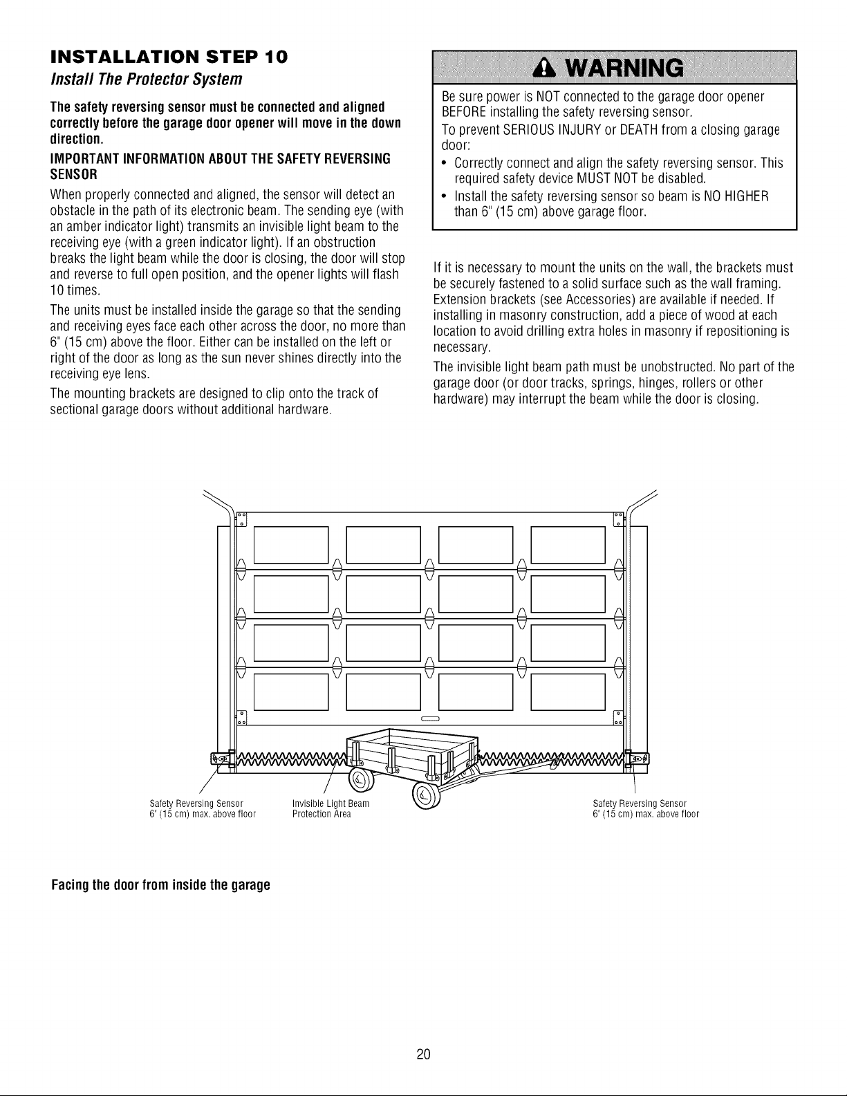
Install TheProtectorSystem
Thesafety reversingsensormust be connectedand aligned
correctlybeforethe garage dooropenerwill move in the down
direction.
IMPORTANTINFORMATIONABOUTTHESAFETYREVERSING
SENSOR
When properly connected andaligned, the sensor will detect an
obstacle in the path of its electronic beam. The sending eye (with
an amber indicator light) transmits an invisible light beamto the
receiving eye (with a green indicator light). If an obstruction
breaksthe light beam while the door is closing, the door will stop
and reverseto full open position, and the opener lights will flash
10 times.
The units must be installed inside the garageso that the sending
and receivingeyesface each other across the door, no more than
6" (15 cm) abovethe floor. Either can be installed on the left or
right of the door as long as the sun never shines directly into the
receiving eye lens.
The mounting brackets are designedto clip onto the track of
sectional garage doors without additional hardware.
Besure power is NOTconnected to the garagedoor opener
BEFOREinstalling the safety reversingsensor.
To preventSERIOUSINJURYor DEATHfrom a closing garage
door:
• Correctly connect and align the safety reversing sensor. This
requiredsafety device MUST NOTbe disabled.
• Install the safety reversing sensor so beam is NO HIGHER
than 6" (15 cm) abovegaragefloor.
If it is necessaryto mount the units on the wall, the brackets must
be securely fastened to a solid surface such as the wall framing.
Extension brackets (seeAccessories) are availableif needed.If
installing in masonry construction, add a piece of wood at each
location to avoid drilling extra holes in masonry if repositioning is
necessary.
The invisible light beam path must be unobstructed. No part of the
garagedoor (or door tracks, springs, hinges, rollers or other
hardware) may interrupt the beam while the door is closing.
]o[
]o[
]÷[
/
Safety Reversing Sensor Invisible Light Beam
6" (15 cm) max. above floor Protection Area
Safety Reversing Sensor
6" (15 cm) max. above floor
Facingthe doorfrom insidethe garage
2O
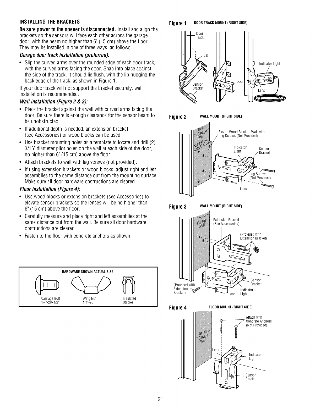
INSTALLINGTHE BRACKETS
Be surepower to the opener is disconnected.Install and align the
brackets so the sensors will face eachother across the garage
door, with the beam no higher than 6" (15 cm) abovethe floor.
They may be installed in one of three ways, as follows.
Garagedoor track installation(preferred):
• Slip the curved arms over the rounded edgeof each door track,
with the curved arms facing the door. Snap into place against
the side of the track. It should lie flush, with the lip hugging the
back edgeof the track, as shown in Figure 1.
If your door track will not support the bracket securely, wall
installation is recommended.
Waft installation (Figure2 & 3):
• Placethe bracket against the wall with curved arms facing the
door. Besure there is enough clearancefor the sensor beamto
be unobstructed.
• If additional depth is needed,an extension bracket
(see Accessories) or wood blocks can be used.
• Use bracket mounting holes as a template to locate and drill (2)
3/16" diameter pilot holes on the wall at each side of the door,
no higher than 6" (15 cm) above the floor.
• Attach bracketsto wall with lag screws (not provided).
• If using extension brackets or wood blocks, adjust right and left
assembliesto the same distance out from the mounting surface.
Make sure all door hardware obstructions arecleared.
Floor installation (Figure4):
• Usewood blocks or extension brackets (seeAccessories) to
elevatesensor brackets so the lenses will be no higher than
6" (15 cm) abovethe floor.
• Carefully measureand place right and left assembliesat the
same distance out from the wall. Besure all door hardware
obstructions are cleared.
• Fastento the floor with concrete anchors as shown.
HARDWARESHOWN ACTUALSIZE
Carriage Bolt Wing Nut Insulated
1/4"-20xl/2" 1/4"-20 Staples
Figure I DOORTRACK MOUNT (RIGHT SIDE)
t Door
, Track
;zz -
Figure2 WALLMOUNT (RIGHT SIDE)
FastenWood Block to Wall with
(Not Provided)
Indicator Sensor
Light
_k Bracket
a
Y L2g._
(Not Provided)
Lens
Figure3
WALLMOUNT (RIGHT SIDE)
Exteos,ooorac et
(SeeAccessories)
(Provided with
!I___:'- _acket)
"" _ Sensor
(Provided with .-__ Bracket
Extension _ b_.. -- I! Indicator
Bracket) ,.v _Lens Light
Figure4
J
FLOORMOUNT (RIGHT SIDE)
Attach with
Concrete Anchors
(Not Provided)
Indicator
Light
Sensor
Bracket
21
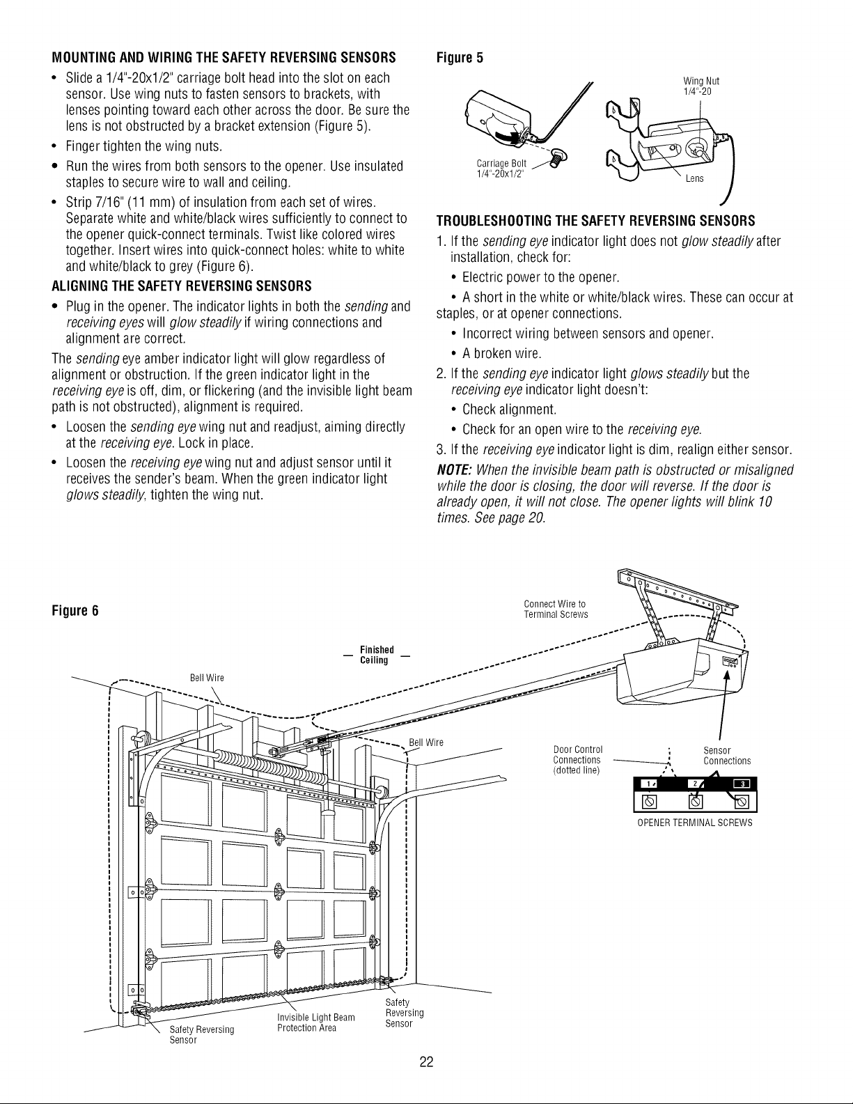
MOUNTINGAND WIRINGTHESAFETYREVERSINGSENSORS
• Slide a 1/4"-20xl/2" carriage bolt headinto the slot on each
sensor. Usewing nuts to fasten sensors to brackets, with
lenses pointing toward each other across the door. Besure the
lens is not obstructed by a bracket extension (Figure 5).
• Finger tighten the wing nuts.
• Runthe wires from both sensors to the opener. Use insulated
staples to secure wire to wall andceiling.
• Strip 7/16" (11 mm) of insulation from each set of wires.
Separatewhite andwhite/black wires sufficiently to connect to
the opener quick-connect terminals. Twist like colored wires
together. Insert wires into quick-connect holes: white to white
and white/black to grey (Figure 6).
ALIGNINGTHESAFETYREVERSINGSENSORS
• Plugin the opener. The indicator lights in both the sending and
receivingeyes will glow steadily if wiring connections and
alignment are correct.
The sending eyeamber indicator light will glow regardlessof
alignment or obstruction. If the green indicator light in the
receiving eyeis off, dim, or flickering (and the invisible light beam
path is not obstructed), alignment is required.
• Loosenthe sending eyewing nut and readjust, aiming directly
at the receiving eye.Lock in place.
• Loosenthe receiving eyewing nut and adjust sensor until it
receivesthe sender's beam. When the green indicator light
glows steadily, tighten the wing nut.
Figure 5
Wing Nut
1/4"-20
Carriage Bolt _
1/4"-20xl/2"
TROUBLESHOOTINGTHESAFETYREVERSINGSENSORS
1. If the sending eye indicator light does not glow steadily after
installation, check for:
• Electric power to the opener.
• A short in the white or white/black wires. These can occur at
staples, or at opener connections.
• Incorrect wiring between sensors andopener.
• A broken wire.
2. If the sending eye indicator light glows steadily but the
receivingeye indicator light doesn't:
• Checkalignment.
• Checkfor an openwire to the receiving eye.
3. If the receiving eye indicator light is dim, realign either sensor.
NOTE: When the invisible beam path is obstructed or misaligned
while the door is closing, the door will reverse. If the door is
already open, it will not close. The opener lights will blink 10
times. Seepage 20.
Figure 6
Finished
Ceiling
Connect Wire to
Terminal Screws
DoorControl ; Sensor
Connections Connections
(dotted line)
OPENERTERMINAL SCREWS
22
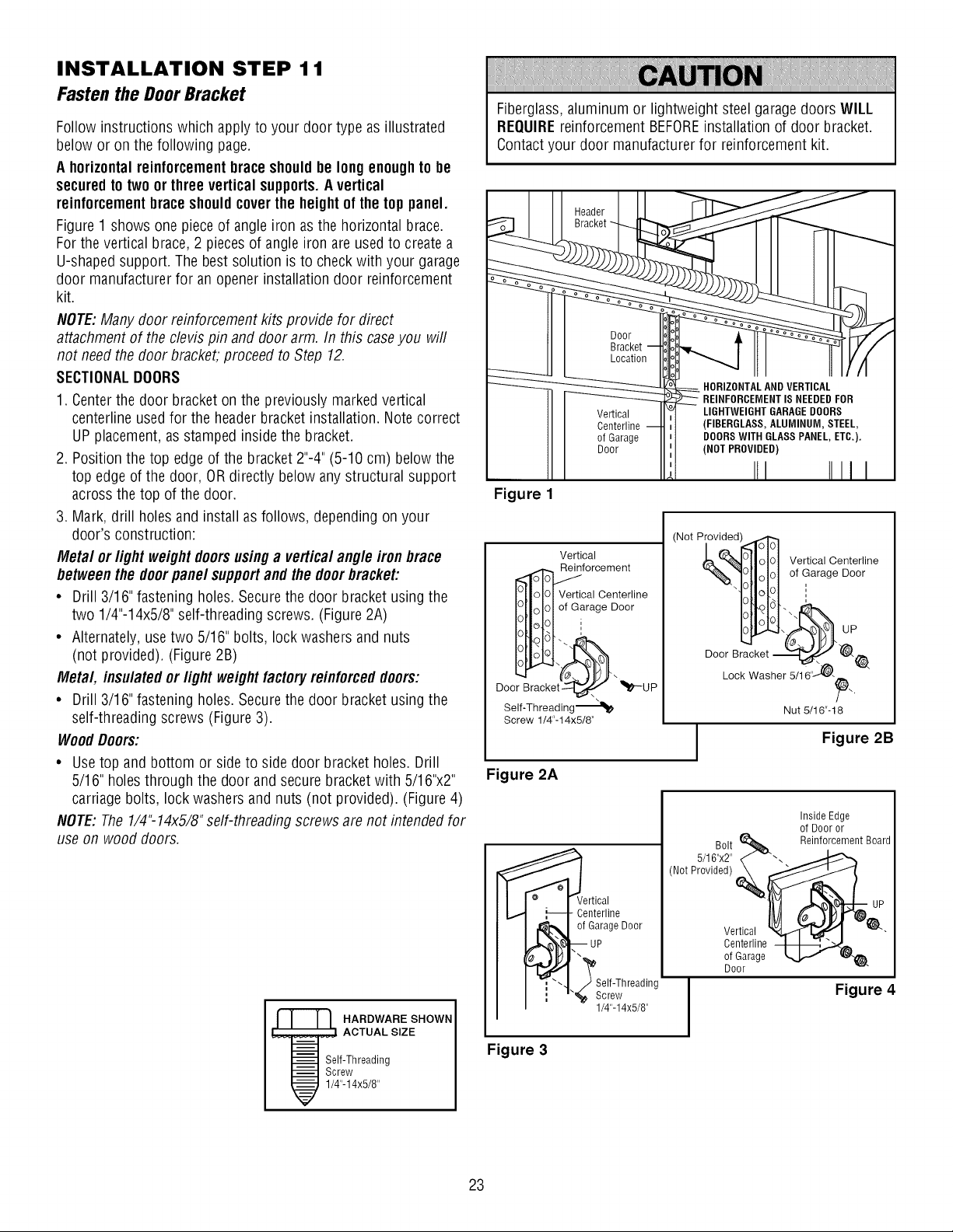
INSTALLATION STEP 1 1
Fasten the DoorBracket
Follow instructions which apply to your door type as illustrated
below or on the following page.
A horizontalreinforcementbrace shouldbe long enoughto be
securedto two or three vertical supports.A vertical
reinforcementbraceshouldcoverthe heightof the top panel.
Figure 1 shows one piece of angle iron as the horizontal brace.
For the vertical brace, 2 pieces of angle iron are used to createa
U-shaped support. The best solution is to check with your garage
door manufacturer for an opener installation door reinforcement
kit.
NOTE:Many door reinforcement kits provide for direct
attachment of the clevis pin and door arm. In this caseyou will
not need the door bracket, proceed to Step 12.
SECTIONALDOORS
1. Centerthe door bracket on the previously marked vertical
centerline used for the header bracket installation. Note correct
UP placement,as stamped inside the bracket.
2. Position the top edge of the bracket 2"-4" (5-10 cm) below the
top edge of the door, OR directly below any structural support
across the top of the door.
3. Mark, drill holes and install as follows, depending on your
door's construction:
Metal orlight weight doorsusing a vertical angle iron brace
betweenthe door panel supportand the doorbracket:
• Drill 3/16" fastening holes. Secure the door bracket using the
two 1/4"-14x5/8" self-threading screws. (Figure 2A)
• Alternately, use two 5/16" bolts, lock washers and nuts
(not provided). (Figure 2B)
Metal, insulatedor light weightfactoryreinforceddoors:
• Drill 3/16" fastening holes. Secure the door bracket using the
self-threading screws (Figure 3).
WoodDoors:
• Usetop and bottom or side to side door bracket holes. Drill
5/16" holes through the door and secure bracket with 5/16"x2"
carriage bolts, lock washers and nuts (not provided). (Figure 4)
NOTE:The 1/4"-14x5/8" self-threading screws are not intended for
use on wood doors.
HARDWARE SHOWN
ACTUAL SIZE
Self-Threading
Screw
1/4"-14x5/8"
Fiberglass,aluminum or lightweight steel garagedoors WILL
REQUIREreinforcement BEFOREinstallation of door bracket.
Contactyour door manufacturer for reinforcement kit.
Figure 1
Door
Bracket
Location
Vertical
Centerline
of Garage
Door
HORIZONTALAND VERTICAL
REINFORCEMENTIS NEEDEDFOR
LIGHTWEIGHT GARAGEDOORS
(FIBERGLASS,ALUMINUM, STEEL,
DOORS WITH GLASS PANEL, ETC.).
(NOT PROVIDED)
III IIII I
Vertical
_fl_,,_olOl Verti:_iC_ri:trline
arage Door
Door gracket_" _-UP
Self-Threading---"_
Screw 1/4"-14x5/8"
Figure 2A
(Not Provided 11_
_'C_% [Io101 VerticalCenterline
"%." [Io101 of Garage Door
- iloH ==
Door Bracket
Lock Washer 5/16'_.
Nut 5/16"- 18
J
Figure 2B
ertical
Centerline
of Garage Door
Self-Threading
Screw
1/4"-14x5/8"
Bolt
5/16"x2" -.
(Not Provided)
Inside Edge
of Door or
Reinforcement Board
Vertical
Centerline
of Garage
Door
Figure 4
Figure 3
23
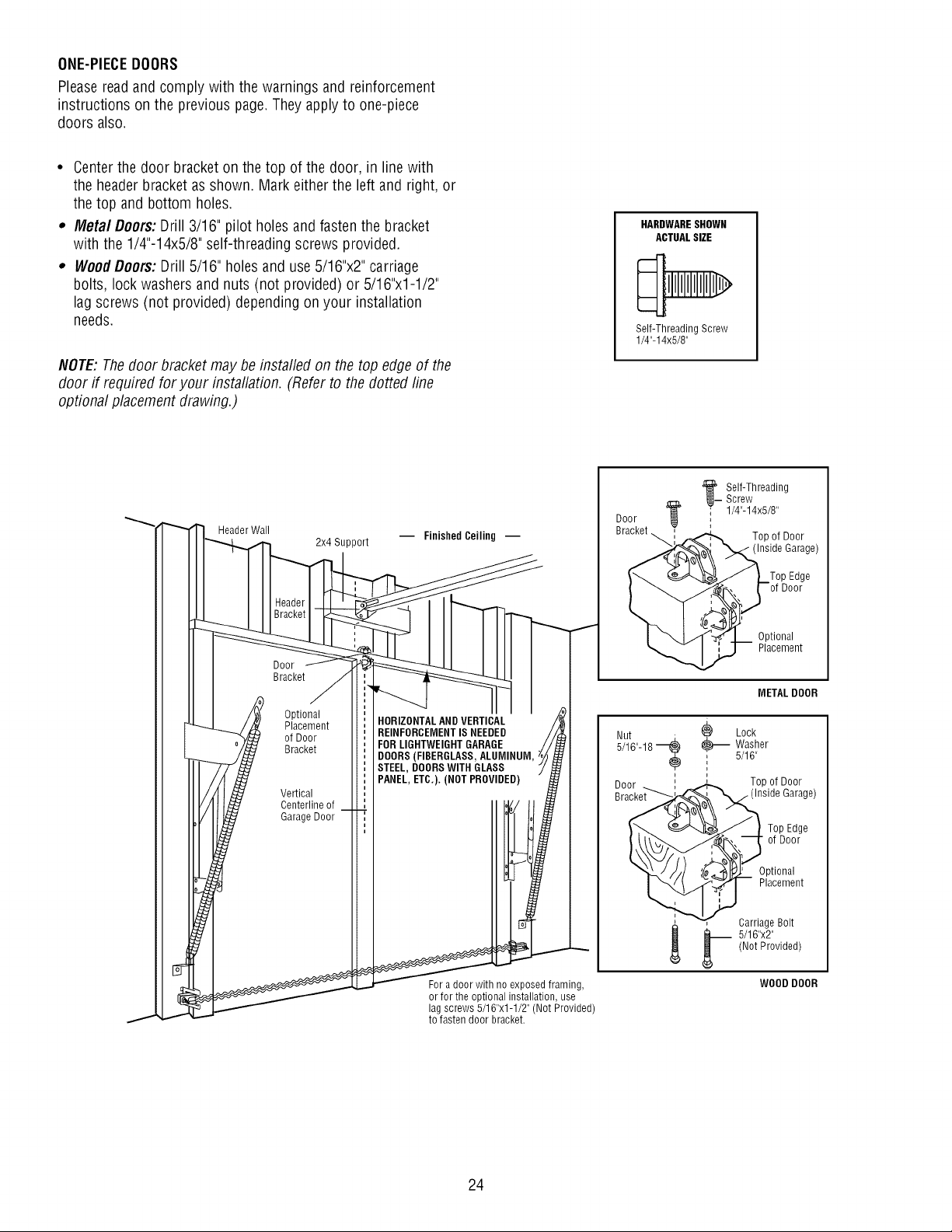
ONE-PIECEDOORS
Please readand comply with the warnings and reinforcement
instructions on the previous page. They apply to one-piece
doors also.
• Centerthe door bracket on the top of the door, in line with
the header bracket as shown. Mark either the left and right, or
the top and bottom holes.
,, Metal Doors: Drill 3/16" pilot holes and fasten the bracket
with the 1/4"-14x5/8" self-threading screws provided.
,, WoodDoors:Drill 5/16" holes and use 5/16"x2" carriage
bolts, lock washers and nuts (not provided) or 5/16"x1-1/2"
lag screws (not provided) depending on your installation
needs.
NOTE:Thedoor bracket may be installed on the top edge of the
door if required for your installation. (Refer to the dotted line
optional placement drawing.)
HARDWARESHOWN
ACTUALSIZE
Self-Threading Screw
1/4"-14x5/8"
Header Wall
2x4 Support
Door
Bracket
Optional
Placement
of Door
Bracket
Vertical
Centerline of
Garage Door
-- Finished Ceiling --
HORIZONTALAND VERTICAL
REINFORCEMENTIS NEEDED
FOR LIGHTWEIGHTGARAGE
DOORS(FIBERGLASS,ALUMINUM,
STEEL, DOORSWITH GLASS
PANEL, ETC.). (NOT PROVIDED)
For a door with no exposed framing,
or for the optional installation, use
lag screws 5/16"x1-1/2" (Not Provided)
to fasten door bracket.
Door
Bracket
•__ Self-Threading
Screw
' 1/4"-14x5/8"
Top of Door
(Inside Garage)
Optional
Placement
METAL DOOR
Nut _) Lock
5/16"-18_ _ Washer
, 5/16"
Top of Door
Garage)
Top Edge
of Door
Optional
Placement
, _ Carriage Bolt
5/16"x2"
(Not Provided)
WOOD DOOR
24
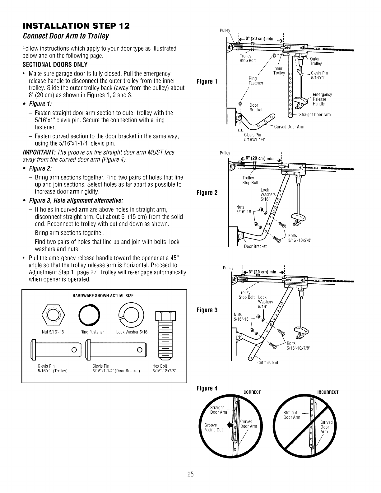
INSTALLATION STEP 12
ConnectDoorArm to Trolley
Follow instructions which apply to your door type as illustrated
below and on the following page.
SECTIONALDOORSONLY
• Make sure garage door is fully closed. Pull the emergency
releasehandleto disconnect the outer trolley from the inner
trolley. Slide the outer trolley back (away from the pulley) about
8" (20 cm) as shown in Figures 1,2 and 3.
• Figure 1:
- Fastenstraight door arm section to outer trolley with the
5/16"x1" clevis pin. Securethe connection with a ring
fastener.
- Fastencurved section to the door bracket in the sameway,
using the 5/16"x1-1/4" clevis pin.
IMPORTANT."Thegroove on the straight door arm MUST face
away from the curved door arm (Figure 4).
• Figure 2:
- Bring arm sections together. Find two pairs of holes that line
up and join sections. Select holes as far apart as possibleto
increasedoor arm rigidity.
• Figure 3, Hole alignment alternative:
- If holes in curved arm are above holes in straight arm,
disconnect straight arm. Cut about 6" (15 cm) from the solid
end. Reconnectto trolley with cut end down as shown.
- Bring arm sections together.
- Find two pairs of holes that line up and join with bolts, lock
washers and nuts.
• Pullthe emergency releasehandletoward the opener at a 45°
angle so that the trolley releasearm is horizontal. Proceedto
Adjustment Step 1, page27. Trolley will re-engageautomatically
when opener is operated.
Figure1
Figure2
Pulley
_ i÷-8" (20 cm) rain. ...) ::
/ Inner II M
/ TrolleyIol "i _Clevis Pin
Ring Iol I 5/16"x1"
2stor I 11
/ HI Emergency
/ IolC _ Release
? Door Iol_ .M Handle
_I Bracket IOl""
I_"_ [_,_ Straight Door Arnl
• _'_...Z._ _ CurvedDoorArm
Clevis Pin
5/16"x 1-1/4"
Pulle
_ ::_÷8"(9 c,.),.i..-_L
Stop Bolt //
Lock /o/ II
W_shers/o/ II
Nuts
5/16"-18 _"_
'-_ _3 Bolts
• Door Bracket _ 5/16'-18x7/8"
HARDWARESHOWN ACTUALSIZE
oo @
Nut5/16"-18 Ring Fastener Lock Washer 5/16"
o,
ClevisPin ClevisPin
5/16"xl"(Trolley) 5/16"x1-1/4"(Door Bracket)
Hex Bolt
5/16"-18x7/8"
Figure3
Cut this end
Bolts
5/16"-18x7/8"
Figure4
Groove
Facing Out
CORRECT INCORRECT
25
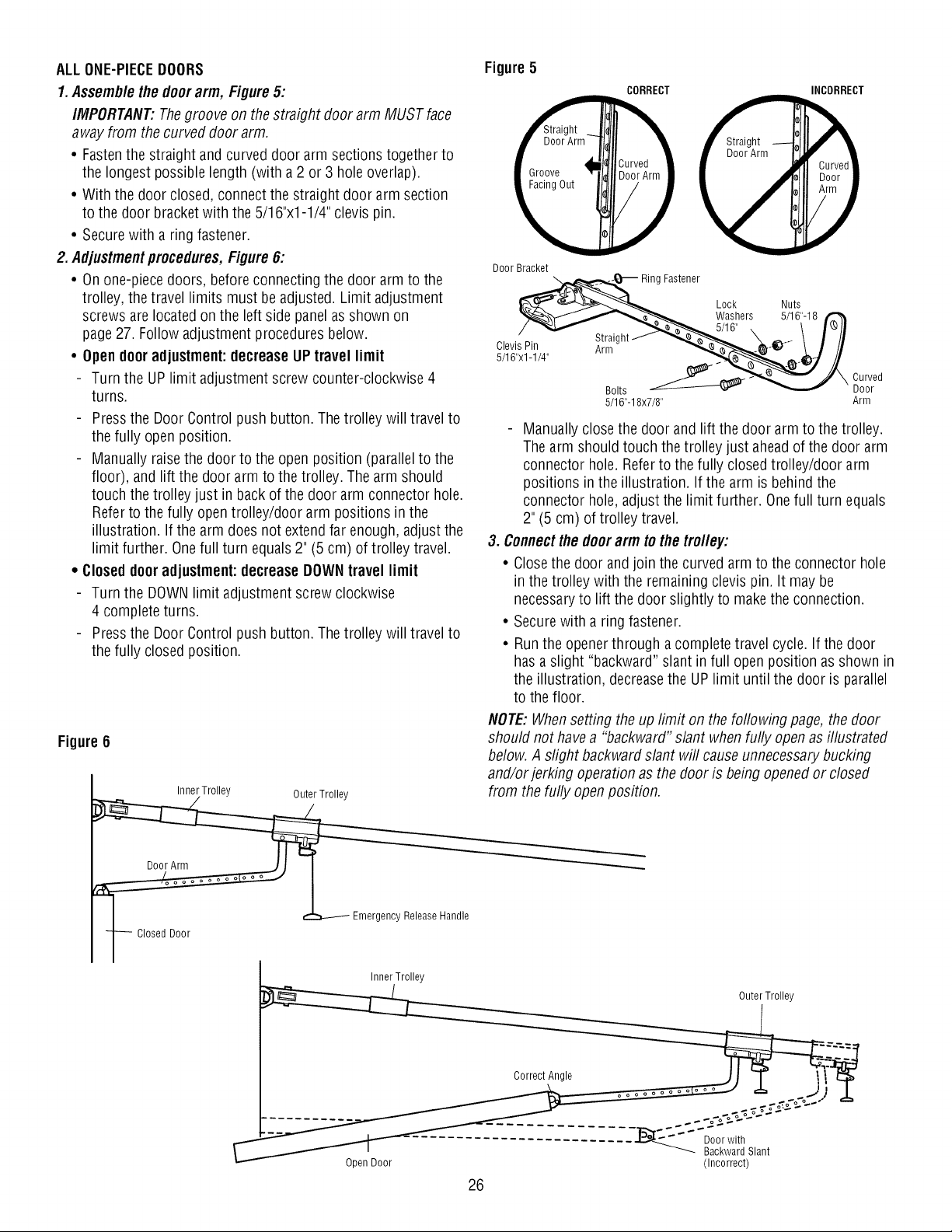
ALLONE-PIECEDOORS
1. Assemb/ethe door arm, Figure5:
IMPORTANT:Thegroove on the straight door arm MUST face
away from the curved door arm.
• Fastenthe straight and curved door arm sections together to
the longest possible length (with a 2 or 3 hole overlap).
• With the door closed, connect the straight door arm section
to the door bracket with the 5/16"x1-1/4" clevis pin.
• Securewith a ring fastener.
2. Adjustmentprocedures,Figure 6:
• Onone-piece doors, before connecting the door arm to the
trolley, the travel limits must be adjusted. Limit adjustment
screws are located on the left side panelas shown on
page27. Follow adjustment procedures below.
• Open dooradjustment:decreaseUP travel limit
Turn the UP limit adjustment screw counter-clockwise 4
turns.
Pressthe Door Control push button. The trolley will travel to
the fully open position.
Manually raise the door to the open position (parallel to the
floor), and lift the door arm to the trolley. The arm should
touch the trolley just in back of the door arm connector hole.
Referto the fully open trolley/door arm positions in the
illustration. If the arm does not extendfar enough, adjust the
limit further. Onefull turn equals 2" (5 cm) of trolley travel.
• Closeddooradjustment:decreaseDOWNtravel limit
Turn the DOWNlimit adjustment screw clockwise
4 complete turns.
Pressthe Door Control push button. The trolley will travel to
the fully closed position.
Figure 6
Inner Trolley Outer Trolley
I _ Emergency Release Handle
F Closed Door
InnerTrolley
Figure5
CORRECT INCORRECT
Door Bracket
_/16 'ing Fastener
Lock Nuts
Washers 5/16"-18
. \ I_!l
Clevi_Pin AStr ightfJ'- \ III
5/16"x1-1/4' ,_ :--_4_,._%e.©j /]
Bolts __ CUo_red
5/16"-18x7/8" Arm
Manually close the door and lift the door arm to the trolley.
The arm should touch the trolley just aheadof the door arm
connector hole. Referto the fully closed trolley/door arm
positions in the illustration. If the arm is behind the
connector hole, adjust the limit further. Onefull turn equals
2" (5 cm) of trolley travel.
3. Connectthe doorarm to the tro//ey:
• Closethe door and join the curved arm to the connector hole
in the trolley with the remaining clevis pin. It may be
necessaryto lift the door slightly to make the connection.
• Secure with a ring fastener.
• Runthe opener through a complete travel cycle. If the door
has a slight "backward" slant in full open position as shown in
the illustration, decreasethe UP limit until the door is parallel
to the floor.
NOTE:Whensetting the up limit on the following page, the door
should not havea "backward" slant when fully open as illustrated
below. A slight backward slant will causeunnecessarybucking
and/or jerking operation as the door is being opened or closed
from the fully openposition.
Outer Trolley
Open Door
26
Backward Slant
(Incorrect)
ADJUSTMENT STEP 1
Adjustthe UPand DOWN TravelLimits
Limit adjustment settings regulatethe points at which the door
will stop when moving up or down.
To operate the opener, press the Door Control push bar. Run the
openerthrough a complete travel cycle.
• Doesthe door open and close completely?
• Doesthe door stay closed and not reverse unintentionally when
fully closed?
If your door passes both of these tests, no limit adjustments are
necessaryunless the reversing test fails (Adjustment Step 3,
page29).
Adjustment procedures are outlined below. Readthe procedures
carefully before proceedingto Adjustment Step 2. Usea
screwdriver to make limit adjustments. Runthe opener througha
completetravel cycle after each adjustment.
NOTE:Repeatedoperation of the openerduring adjustment
procedures may cause the motor to overheatand shut off. Simply
wait 15 minutes and try again.
NOTE:If anything interferes with the door's upward travel, it will
stop. If anything interferes with the door's downward travel
(including binding or unbalanced doors), it will reverse.
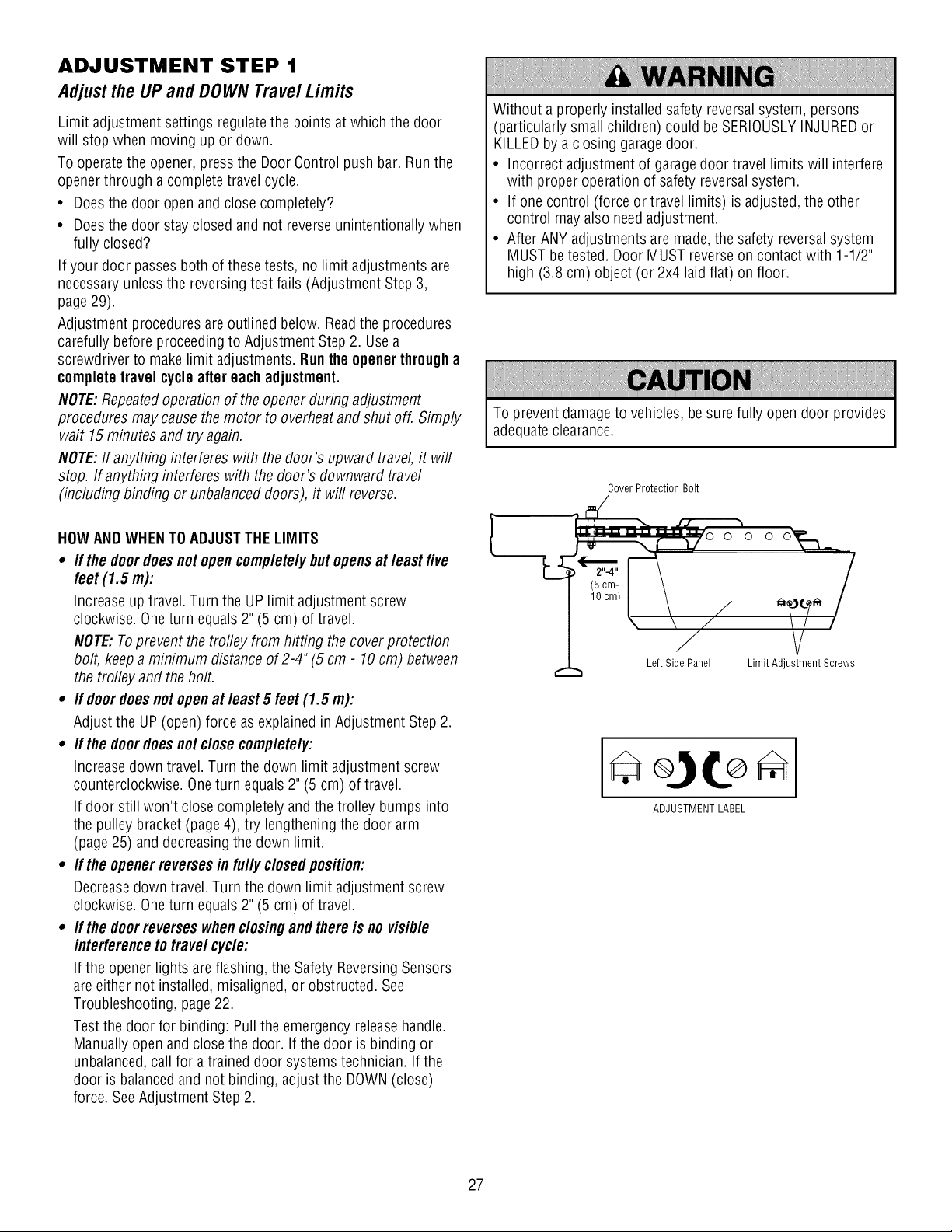
HOWANDWHENTO ADJUSTTHE LIMITS
• If the doordoesnot opencompletelybut opensat least five
feet (1.5 m):
Increaseup travel. Turn the UP limit adjustment screw
clockwise. Oneturn equals 2" (5 cm) of travel.
NOTE:Toprevent the trofley from hitting the coverprotection
bolt, keep a minimum distance of 2-4"(5 cm - 10cm) between
the trolley and the bolt.
• If doordoes not openat least 5 feet (1.5 m):
Adjust the UP (open) force as explained in Adjustment Step 2.
• If the doordoesnot close completely:
Increasedown travel. Turn the down limit adjustment screw
counterclockwise. Oneturn equals 2" (5 cm) of travel.
If door still won't close completely and the trolley bumps into
the pulley bracket (page 4), try lengthening the door arm
(page 25) anddecreasing the down limit.
• If the openerreversesin fully closedposition:
Decreasedown travel. Turn the down limit adjustment screw
clockwise. Oneturn equals 2" (5 cm) of travel.
• If the doorreverseswhen closingand there is no visible
interferenceto travel cycle:
If the opener lights areflashing, the Safety ReversingSensors
are either not installed, misaligned, or obstructed. See
Troubleshooting, page 22.
Test the door for binding: Pull the emergency releasehandle.
Manually open and close the door. If the door is binding or
unbalanced,call for a trained door systems technician. If the
door is balancedand not binding, adjust the DOWN(close)
force. SeeAdjustment Step 2.
Without a properly installed safety reversalsystem, persons
(particularly small children) could be SERIOUSLYINJUREDor
KILLEDby a closing garagedoor.
• Incorrect adjustment of garage door travel limits will interfere
with proper operation of safety reversalsystem.
• If one control (force or travel limits) is adjusted, the other
control mayalso need adjustment.
• After ANY adjustments are made, the safety reversal system
MUST be tested. Door MUST reverseon contact with 1-1/2"
high (3.8 cm) object (or 2x4 laid flat) on floor.
To preventdamage to vehicles, be sure fully open door provides
adequateclearance.
o o'_.__
Limit Adjustment Screws
ADJUSTMENT LABEL
27
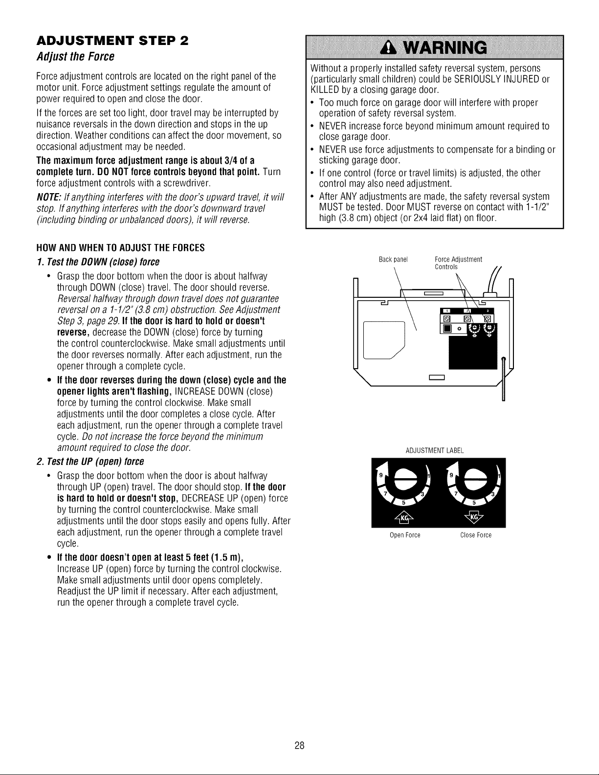
ADJUSTMENT STEP 2
Adjustthe Force
Forceadjustment controls are located on the right panelof the
motor unit. Forceadjustment settings regulate the amount of
power required to open andclose the door.
If the forces are set too light, door travel may be interrupted by
nuisance reversals in the down direction and stops in the up
direction. Weather conditions can affect the door movement, so
occasional adjustment may be needed.
Themaximum force adjustmentrange is about3/4 of a
completeturn. DO NOTforce controlsbeyondthat point. Turn
force adjustment controls with a screwdriver.
NOTE:If anything interferes with the door's upward travel, it will
stop. If anything interferes with the door's downward travel
(including binding or unbalanced doors), it will reverse.
Without a properly installed safety reversalsystem, persons
(particularly small children) could be SERIOUSLYINJUREDor
KILLEDby a closing garagedoor.
• Too much force on garagedoor will interfere with proper
operation of safety reversalsystem.
• NEVERincreaseforce beyond minimum amount requiredto
close garagedoor.
• NEVERuseforce adjustments to compensatefor a binding or
sticking garagedoor.
• If one control (force or travel limits) is adjusted, the other
control mayalso need adjustment.
• After ANY adjustments are made, the safety reversal system
MUST be tested. Door MUST reverseon contact with 1-1/2"
high (3.8 cm) object (or 2x4 laid flat) on floor.
HOWANDWHENTO ADJUSTTHE FORCES
1. Testthe DOWN (close) force
• Grasp the door bottom when the door is about halfway
through DOWN(close) travel. The door should reverse.
Reversalhalfway through down travel does not guarantee
reversalon a 1-1/2" (3.8 cm) obstruction. SeeAdjustment
Step3, page 29. If the door is hardto holdor doesn't
reverse, decreasethe DOWN(close) force by turning
the control counterclockwise. Make small adjustments until
the door reverses normally. After each adjustment, run the
openerthrough a complete cycle.
• If the doorreverses duringthe down(close) cycleand the
openerlights aren't flashing, INCREASEDOWN(close)
force by turning the control clockwise. Make small
adjustments until the door completes a close cycle. After
each adjustment, run the opener through acomplete travel
cycle. Do not increase the force beyond the minimum
amount required to close the door.
2. Testthe UP (open) force
• Grasp the door bottom when the door is about halfway
through UP (open) travel. The door should stop. If the door
is hardto hold or doesn'tstop, DECREASEUP (open) force
by turning the control counterclockwise. Make small
adjustments until the door stops easily and opens fully. After
each adjustment, run the opener through acomplete travel
cycle.
• If the doordoesn't openat least 5 feet (1.5 m),
IncreaseUP (open) force by turning the control clockwise.
Make small adjustments until door opens completely.
Readjustthe UP limit if necessary.After each adjustment,
run the openerthrough a complete travel cycle.
Back panel
\
I\
Force Adjustment
Controls
ADJUSTMENT LABEL
Open Force
Close Force
28
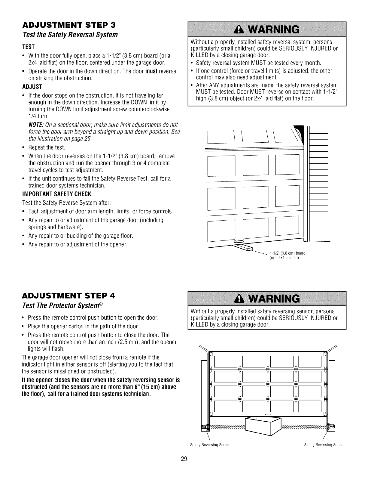
ADJUSTMENT STEP 3
Testthe SafetyReversalSystem
TEST
• With the door fully open, place a 1-1/2" (3.8 cm) board (or a
2x4 laid flat) on the floor, centered under the garagedoor.
• Operatethe door in the down direction. The door must reverse
on striking the obstruction.
ADJUST
• If the door stops on the obstruction, it is not traveling far
enough in the down direction. Increasethe DOWNlimit by
turning the DOWNlimit adjustment screw counterclockwise
1/4 turn.
NOTE:Ona sectional door, make sure limit adjustments do not
force the door arm beyond a straight up and down position. See
the illustration on page 25.
• Repeatthe test.
• When the door reverses on the 1-1/2" (3.8 cm) board, remove
the obstruction and run the openerthrough 3 or 4 complete
travel cycles to test adjustment.
• If the unit continues to fail the Safety ReverseTest, call for a
trained door systems technician.
IMPORTANTSAFETYCHECK:
Test the Safety ReverseSystem after:
• Eachadjustment of door arm length, limits, or force controls.
• Any repair to or adjustment of the garagedoor (including
springs and hardware).
• Any repair to or buckling of the garagefloor.
• Any repair to or adjustment of the opener.
Without a properly installed safety reversalsystem, persons
(particularly small children) could be SERIOUSLYINJUREDor
KILLEDby a closing garagedoor.
• Safety reversalsystem MUSTbe tested everymonth.
• If one control (force or travel limits) is adjusted, the other
control mayalso need adjustment.
• After ANY adjustments are made, the safety reversal system
MUST be tested. Door MUST reverseon contact with 1-1/2"
high (3.8 cm) object (or 2x4 laid flat) on the floor.
I
(or a 2x4 laid flat)
ADJUSTMENT STEP 4
Test TheProtectorSystem®
• Pressthe remote control push button to open the door.
• Placethe opener carton in the path of the door.
• Pressthe remote control push button to close the door. The
door will not move more than an inch (2.5 cm), and the opener
lights will flash.
The garagedoor openerwill not closefrom a remote if the
indicator light in either sensor is off (alerting you to the fact that
the sensor is misaligned or obstructed).
If the openercloses the door whenthe safety reversingsensoris
obstructed(and the sensorsare no more than 6"(15 cm) above
the floor), call for a trained doorsystemstechnician.
Without a properly installed safety reversing sensor, persons
(particularly small children) could be SERIOUSLYINJUREDor
KILLEDby a closing garagedoor.
Safety Reversing Sensor Safety Reversing Sensor
29
OPERATION
IMPORTANTSAFETYINSTRUCTIONS
To reducethe riskof SEVEREINJURYor DEATH:
1. READAND FOLLOWALL WARNINGSAND INSTRUCTIONS.
2. ALWAYS keep remote controls out of reach of children. NEVER
permit children to operate or play with garage door control
push buttons or remote controls.
3. ONLYactivategaragedoor when it can beseen clearly, it
is properly adjusted, and there areno obstructions to door
travel.
4. ALWAYS keepgaragedoor in sight until completely closed.
NOONESHOULDCROSSTHE PATHOFTHEMOVINGDOOR.
5. NOONESHOULDGO UNDERA STOPPED,PARTIALLY
OPENEDDOOR.
6. If possible, use emergency releasehandleto disengagetrolley
ONLYwhen garage door is CLOSED.Weakor broken springs
or unbalanced door could result in an open door falling rapidly
and/or unexpectedly,causing SEVEREINJURYor DEATH.
7. NEVERuse emergency releasehandle unless garage doorway
is clear of persons and obstructions.
8. NEVERuse handleto pull garagedoor open or closed. If rope
knot becomes untied, you could fall.
9. If one control (force or travel limits) is adjusted, the other
control mayalso need adjustment.
10. After ANY adjustments are made,the safety reversal system
MUST be tested.
11. Safety reversal system MUST be tested every month. Garage
door MUST reverseon contact with 1-1/2" high (3.8 cm)
object (or a 2x4 laid flat) on the floor. Failureto adjust the
garagedoor opener properly may causeSEVEREINJURY or
DEATH.
12. ALWAYSKEEPGARAGEDOORPROPERLYBALANCED
(see page3). An improperly balanced door may NOTreverse
when required and could result in SEVEREINJURY or
DEATH.
13. ALL repairs to cables, spring assemblies and other
hardware,ALL of which are under EXTREMEtension, MUST
be made by a trained door systems technician.
14. ALWAYSdisconnect electric power to garage door opener
BEFOREmaking ANY repairs or removing covers.
15SAVETHESEINSTRUCTIONS.
Using Your Garage Door Opener
Your Security-I-® opener and hand-held remote control have been
factory-set to a matching code which changeswith each use,
randomly accessing over 100 billion new codes. Your opener will
operate with up to eight Security.I.® remote controls and one
Security-I-® KeylessEntry System. If you purchase a new remote,
or if you wish to deactivateany remote, follow the instructions in
the Programming section.
Activateyour opener withany of the following:
• Thehand-held Remote Control: Hold the large push button
down until the door starts to move.
• The wall-mounted Door Controh Hold the push button or bar
down until the door starts to move.
• The KeylessEntry (SeeAccessories): If provided with your
garagedoor opener, it must be programmed before use. See
Programming.
Whenthe opener is activated(with the safety reversingsensor
correctlyinstalled and aligned)
1. If open, the door will close. If closed, it will open.
2. If closing, the door will reverse.
3. If opening, the door will stop.
4. If the door has been stopped in a partially open position, it will
close.
5. If obstructed while closing, the door will reverse. If the
obstruction interrupts the sensor beam, the opener lights will
blink for five seconds.
6. If obstructed while opening, the door will stop.
7. If fully open, the door will not close when the beam is broken.
The sensor has no effect in the opening cycle.
If the sensor is not installed, or is misaligned, the door won't
close from a hand-held remote. However,you can close the door
with the Door Control, the Outdoor Key Switch, or Keyless Entry,
if you activate them until down travel is complete. If you release
them too soon, the door will reverse.
Theopener lightswill turn on under the following conditions:
when the opener is initially plugged in; when power is restored
after interruption; when the opener is activated.
Theywill turn off automatically after 4-1/2 minutes. Bulb size is
A19. Bulb power is 75 watts maximum.
3O
Usingthe Wall-MountedDoor Control
THEDOORCONTROLBUTTON
Pressthe lighted push button to open or close
the door. Pressagainto reverse the door during
the closing cycle or to stop the door while it's
opening.
To Openthe DoorManually
To prevent possible SERIOUSINJURYor DEATHfrom a falling
garagedoor:
• If possible, use emergency releasehandleto disengage
trolley ONLYwhen garage door is CLOSED.Weakor broken
springs or unbalanceddoor could result in an open door
falling rapidly and/or unexpectedly.
• NEVERuse emergency releasehandleunless garage
doorway is clear of persons and obstructions.
• NEVERuse handle to pull door open or closed. If rope knot
becomes untied, you could fall.
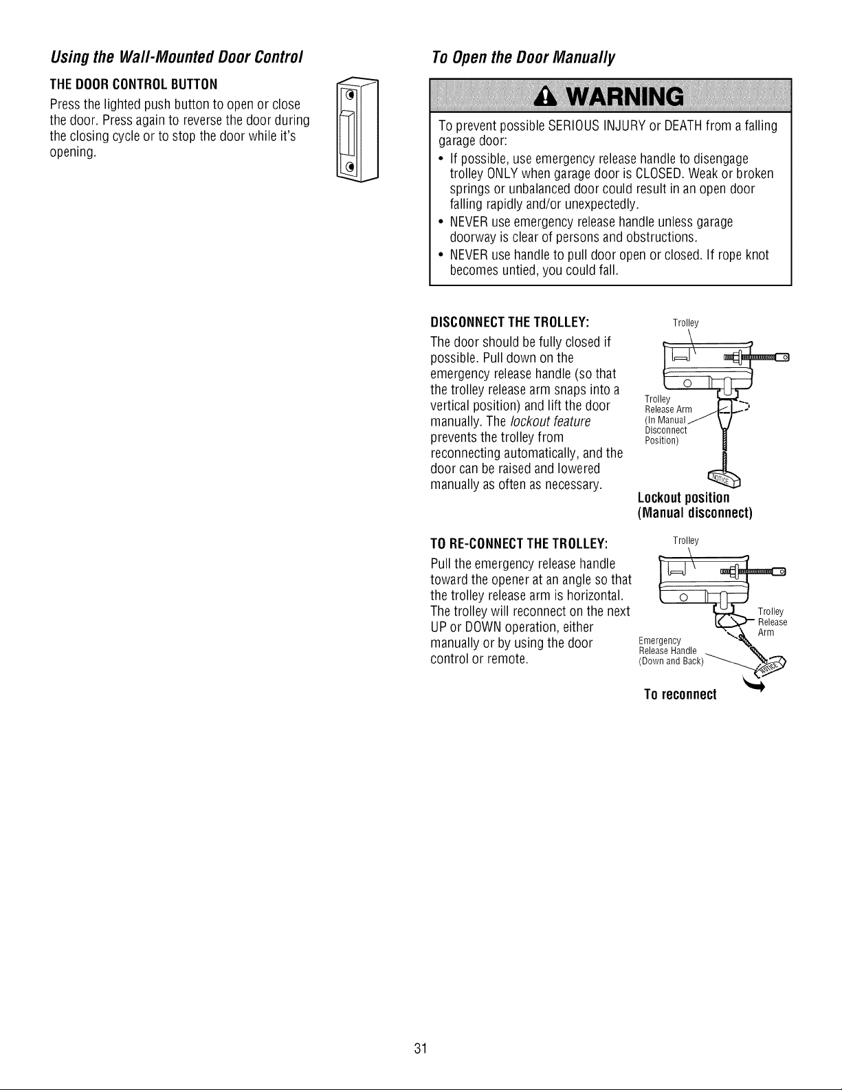
DISCONNECTTHETROLLEY:
The door should befully closed if
possible. Pull down on the
emergency releasehandle (so that
the trolley releasearm snaps into a
vertical position) and lift the door
manually. The lockout feature
prevents the trolley from
reconnecting automatically, and the
door can be raised and lowered
manually as often as necessary.
TO RE-CONNECTTHETROLLEY:
Pull the emergency releasehandle
toward the opener at an angle so that
the trolley releasearm is horizontal.
The trolley will reconnect on the next
UP or DOWNoperation, either
manually or by using the door
control or remote.
Trolley
Disconnect
Position)
Lockoutposition
(Manual disconnect)
Trolley
\
Release
........ -'_. Arm
Emergency
Release Handle _x.
(Down and Back)_
To reconnect
31
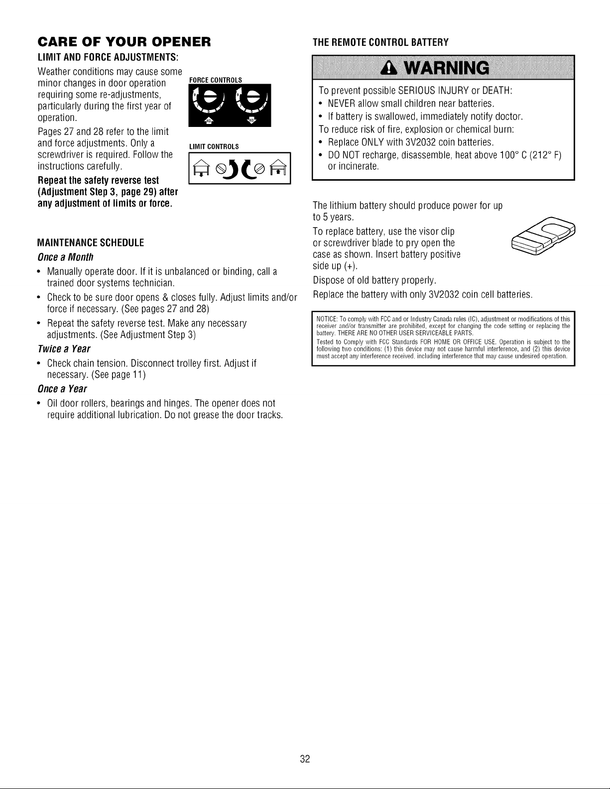
CARE OF YOUR OPENER
LIMIT AND FORCEADJUSTMENTS:
Weather conditions may causesome
minor changesin door operation
requiring some re-adjustments,
particularly during the first year of
operation.
Pages27 and 28 refer to the limit
andforce adjustments. Only a
screwdriver is required. Follow the
instructions carefully.
Repeatthe safety reversetest
(AdjustmentStep3, page 29) after
any adjustmentof limits or force.
FORCECONTROLS
LIMIT CONTROLS
MAINTENANCESCHEDULE
Oncea Month
• Manually operate door. If it is unbalancedor binding, call a
trained door systems technician.
• Checkto be sure door opens & closes fully. Adjust limits and/or
force if necessary. (Seepages 27 and 28)
• Repeatthe safety reversetest. Make any necessary
adjustments. (SeeAdjustment Step 3)
Twicea Year
• Checkchain tension. Disconnect trolley first. Adjust if
necessary. (Seepage 11)
Oncea Year
• Oil door rollers, bearings and hinges. The opener does not
requireadditional lubrication. Do not greasethe door tracks.
THE REMOTECONTROLBATTERY
To prevent possible SERIOUSINJURYor DEATH:
• NEVERallow small children near batteries.
• If battery is swallowed, immediately notify doctor.
To reduce risk of fire, explosion or chemical burn:
• ReplaceONLYwith 3V2032 coin batteries.
• DO NOTrecharge,disassemble, heat above 100° C (212° F)
or incinerate.
The lithium battery should produce power for up
to 5 years.
To replacebattery, usethe visor clip
or screwdriver bladeto pry open the
caseas shown. Insert battery positive
side up (+).
Dispose of old battery properly.
Replacethe battery with only 3V2032 coin cell batteries.
NOTICE:To comply with FCCand or IndustryCanadarules (IC), adjustmentor modifications of this
receiverand/or transmitter are prohibited, except for changing the code setting or replacing the
battery.THEREARENOOTHERUSERSERVICEABLEPARTS.
Tested to Complywith FCC Standards FORHOME OR OFFICEUSE. Operationis subject to the
following two conditions: (1) this device may not cause harmful interference,and (2) this device
must acceptany interference received,including interferencethat may causeundesired operation.
32
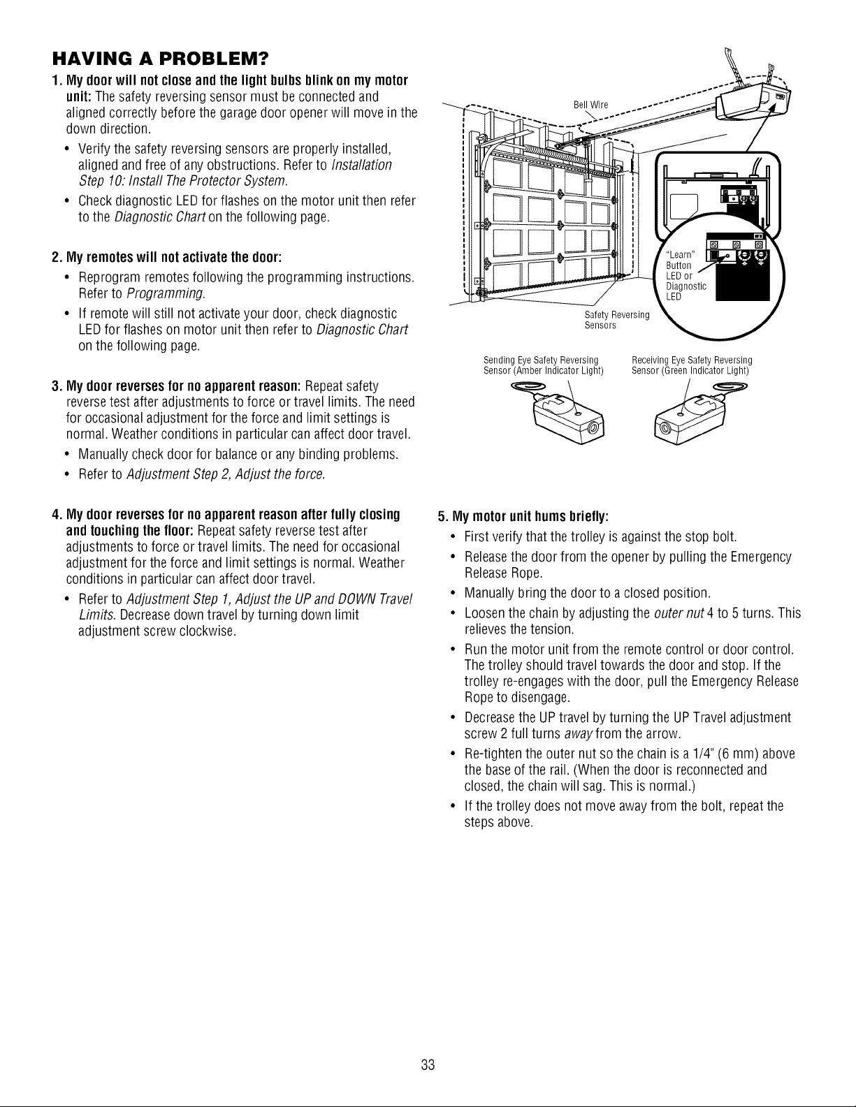
HAVING A PROBLEM?
1. My doorwill notclose and the lightbulbs blinkon my motor
unit: The safety reversing sensor must beconnected and
aligned correctly before the garagedoor openerwill move in the
down direction.
• Verify the safety reversing sensors are properly installed,
aligned andfree of any obstructions. Refer to Installation
Step 10: Instafl TheProtector System.
• Checkdiagnostic LEDfor flashes on the motor unit then refer
to the Diagnostic Charton the following page.
2. My remoteswill notactivate the door:
• Reprogram remotes following the programming instructions.
Referto Programming.
• If remotewill still not activateyour door, check diagnostic
LEDfor flashes on motor unit then refer to Diagnostic Chart
on the following page.
3. My doorreversesfor no apparentreason:Repeatsafety
reversetest after adjustments to force or travel limits. The need
for occasional adjustment for the force and limit settings is
normal. Weather conditions in particular can affect door travel.
• Manually check door for balanceor any binding problems.
• Referto Adjustment Step 2, Adjust the force.
Bell Wire
Safety Reversing
Sensors
Sending EyeSafety Reversing
Sensor (Amber Indicator Light)
Receiving Eye Safety Reversing
Sensor (Green Indicator Light)
4. My doorreversesfor no apparentreasonafter fully closing
andtouchingthe floor: Repeatsafety reverse test after
adjustments to force or travel limits. The needfor occasional
adjustment for the force and limit settings is normal. Weather
conditions in particular can affect door travel.
• Referto Adjustment Step 1, Adjust the UPand DOWN Travel
Limits. Decreasedown travel by turning down limit
adjustment screw clockwise.
5. My motorunit hums briefly:
• First verify that the trolley is against the stop bolt.
• Releasethe door from the opener by pulling the Emergency
ReleaseRope.
• Manually bring the door to a closed position.
• Loosen the chain by adjusting the outernut4 to 5 turns. This
relievesthe tension.
• Run the motor unit from the remote control or door control.
The trolley should travel towards the door and stop. If the
trolley re-engageswith the door, pull the Emergency Release
Rope to disengage.
• Decreasethe UPtravel by turning the UPTravel adjustment
screw 2 full turns awayfrom the arrow.
• Re-tighten the outer nut so the chain is a 1/4" (6 mm) above
the baseof the rail. (When the door is reconnectedand
closed, the chain will sag. This is normal.)
• If the trolley does not move awayfrom the bolt, repeatthe
steps above.
33
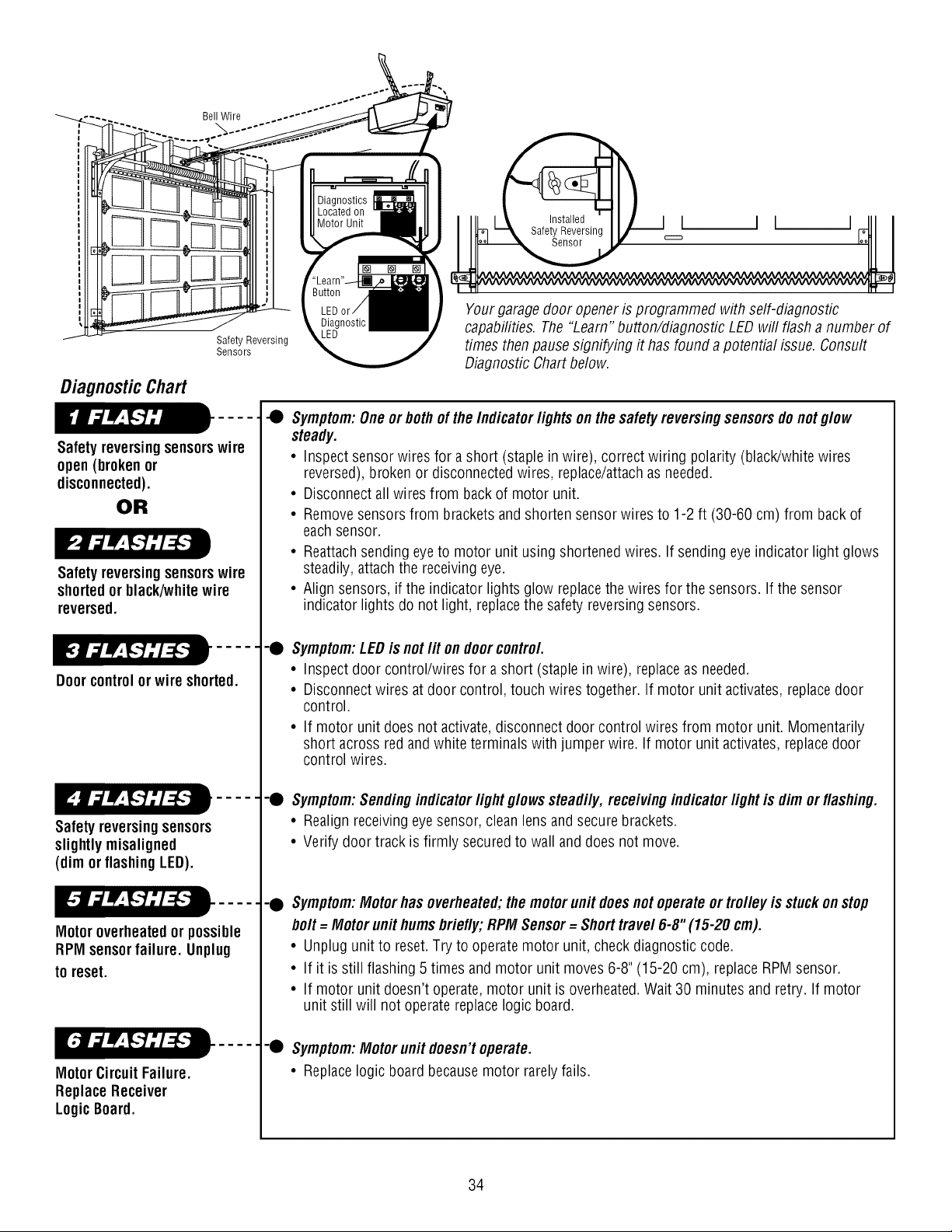
Bell Wire
Diagnostic Chart
Safety Reversing
Sensors
Safetyreversingsensorswire
open(broken or
disconnected).
OR
Safetyreversingsensorswire
shortedor black/whitewire
reversed.
Doorcontrolorwire shorted.
Safetyreversingsensors
slightly misaligned
(dim orflashingLED).
Motoroverheatedor possible
RPMsensorfailure. Unplug
to reset.
MotorCircuitFailure.
ReplaceReceiver
LogicBoard.
I 1
Yourgarage door openeris programmed with self-diagnostic
capabilities. The "Learn" button/diagnostic LED will flasha number of
times then pause signifying it has found a potential issue. Consult
Diagnostic Chartbelow.
• Symptom:One or both of the Indicator fights on the safety reversingsensorsdonotglow
steady.
• Inspect sensor wires for a short (staple in wire), correct wiring polarity (black/white wires
reversed), broken or disconnected wires, replace/attachas needed.
• Disconnect all wires from backof motor unit.
• Remove sensors from brackets and shorten sensor wires to 1-2 ft (30-60 cm) from back of
each sensor.
• Reattach sending eye to motor unit using shortenedwires. If sending eye indicator light glows
steadily, attach the receiving eye.
• Align sensors, if the indicator lights glow replacethe wires for the sensors. If the sensor
indicator lights do not light, replacethe safety reversing sensors.
-• Symptom:LEDis not lit on doorcontrol.
• Inspect door control/wires for a short (staple in wire), replaceas needed.
• Disconnect wires at door control, touch wires together. If motor unit activates, replacedoor
control.
• If motor unit does not activate, disconnect door control wires from motor unit. Momentarily
short across red and white terminals with jumper wire. If motor unit activates,replace door
control wires.
-• Symptom:Sendingindicatorfight glowssteadily, receiving indicatorfight is dim or flashing.
• Realign receiving eye sensor, clean lens and secure brackets.
• Verify door track is firmly secured to wall and does not move.
-• Symptom:Motor has overheated;the motorunit doesnotoperate or trolley is stuckonstop
bolt = Motor unit humsbriefly; RPM Sensor= Shorttravel 6-8" (15-20 cm).
• Unplug unit to reset. Try to operate motor unit, check diagnostic code.
• If it is still flashing 5 times and motor unit moves 6-8" (15-20 cm), replace RPM sensor.
• If motor unit doesn't operate, motor unit is overheated.Wait 30 minutes and retry. If motor
unit still will not operate replace logic board.
...... • Symptom:Motor unit doesn'toperate.
• Replacelogic board because motor rarely fails.
34
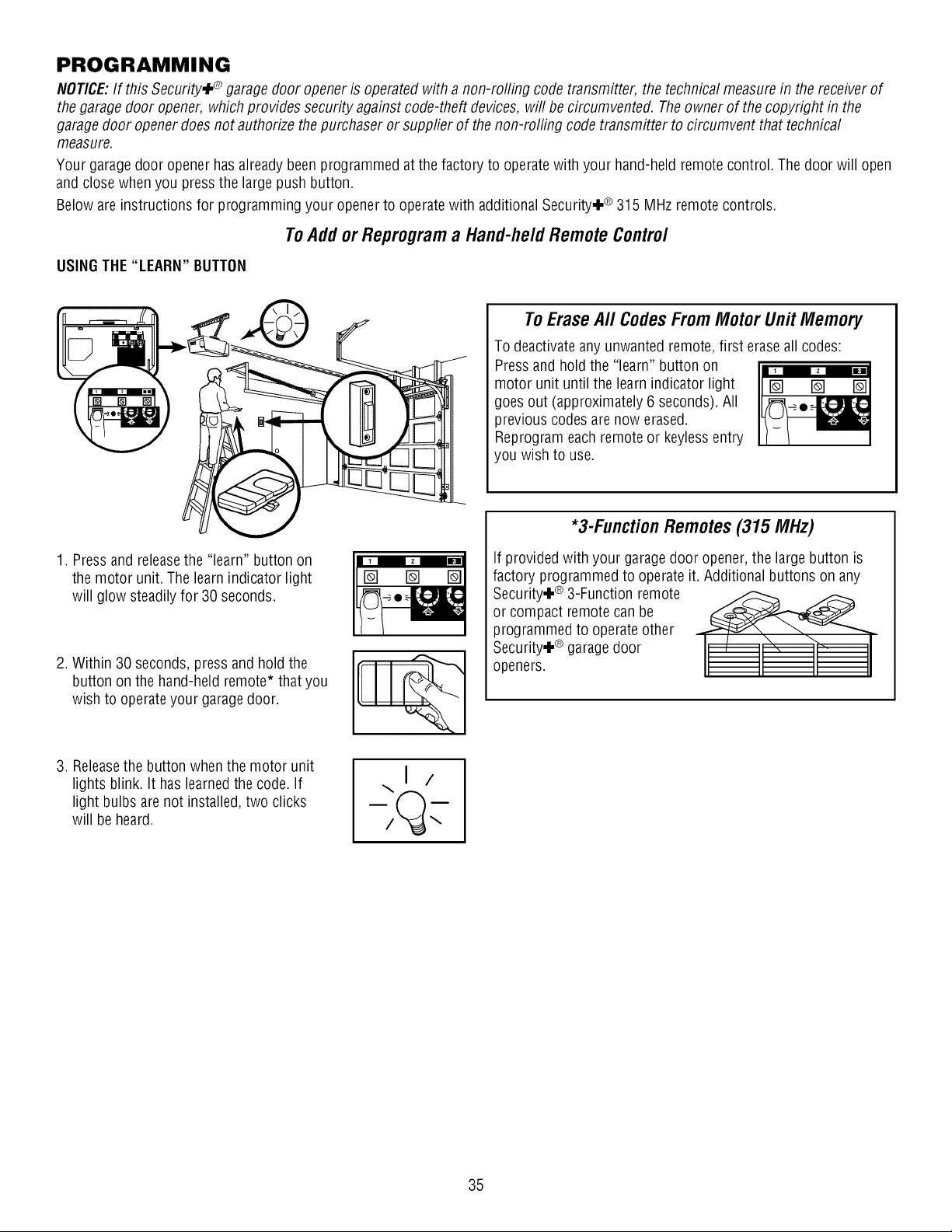
PROGRAMMING
NOTICE:If this Security,I_ garagedoor opener is operated with a non-rolling code transmitter, the technical measurein the receiver of
the garagedoor opener, which provides security against code-theft devices, will be circumvented. Theowner of the copyright in the
garage door opener does not authorize the purchaser or supplier of the non-rolling code transmitter to circumvent that technical
measure.
Your garage door opener has already beenprogrammed at the factory to operatewith your hand-held remotecontrol. The door will open
and close when you pressthe large push button.
Below are instructions for programming your opener to operatewith additional Security÷ ® 315 MHz remotecontrols.
ToAdd or Reprogram a Hand-held Remote Control
USINGTHE "LEARN" BUTTON
To Erase All Codes From Motor Unit Memory
To deactivateany unwanted remote, first erase all codes:
Pressand hold the "learn" button on
motor unit until the learn indicator light
goes out (approximately 6 seconds). All
previous codes are now erased.
Reprogram each remote or keylessentry
you wish to use.
1. Pressand releasethe "learn" button on
the motor unit. The learnindicator light
will glow steadily for 30 seconds.
2. Within 30 seconds, press and hold the
button on the hand-held remote* that you
wish to operate your garagedoor.
3. Releasethe button when the motor unit
lights blink. It has learnedthe code. If
light bulbs are not installed, two clicks
will be heard.
\1 /
*3-Function Remotes (315 MHz)
If provided with your garagedoor opener, the large button is
factory programmed to operate it. Additional buttons on any
Security÷ ® 3-Function remote _ _
or compact remotecan be
programmed to operate other
Security÷ ® garagedoor
openers.
35
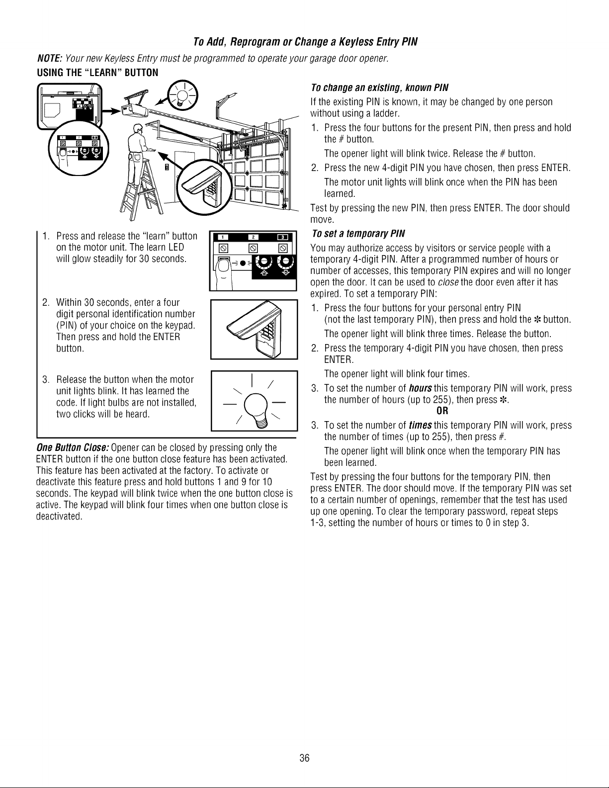
To Add, Reprogram or Change a Keyless Entry PIN
NOTE:Your new KeylessEntry must beprogrammed to operateyour garage door opener.
USINGTHE "LEARN" BUTTON
1. Press and releasethe "learn" button
on the motor unit. The learn LED
will glow steadily for 30 seconds.
.
Within 30 seconds, enter a four
digit personal identification number
(PIN) of your choice on the keypad.
Then pressand hold the ENTER
button.
. Releasethe button when the motor
unit lights blink. It has learnedthe
code. If light bulbs are not installed,
two clicks will be heard.
I /
One ButtonC/ose:Openercan beclosed by pressing only the
ENTERbutton if the one button close feature has been activated.
This feature has beenactivated at the factory. To activate or
deactivatethis feature press and hold buttons 1 and 9 for 10
seconds.The keypad will blink twice when the one button close is
active. The keypadwill blink four times when one button close is
deactivated.
Tochangean existing, knownPIN
If the existing PIN is known, it may bechanged by one person
without using a ladder.
1. Pressthe four buttons for the present PIN, then press and hold
the # button.
The opener light will blink twice. Releasethe # button.
2. Pressthe new 4-digit PINyou have chosen, then press ENTER.
The motor unit lights will blink once when the PIN has been
learned.
Test by pressing the new PIN, then press ENTER.The door should
move.
Toset a temporaryPIN
You may authorize accessby visitors or service peoplewith a
temporary 4-digit PIN. After a programmed number of hours or
number of accesses,this temporary PIN expires and will no longer
openthe door. It can be used to closethe door even after it has
expired.To set a temporary PIN:
1. Pressthe four buttons foryour personal entry PIN
(not the last temporary PIN), then press and hold the _, button.
The opener light will blink three times. Releasethe button.
2. Pressthe temporary 4-digit PIN you have chosen, then press
ENTER.
The opener light will blink four times.
3. To set the number of hoursthistemporary PIN will work, press
the number of hours (up to 255), then press _,.
OR
3. To set the number of timesthis temporary PINwill work, press
the number of times (up to 255), then press #.
The opener light will blink once when the temporary PIN has
beenlearned.
Test by pressing the four buttons for the temporary PIN, then
press ENTER.The door should move. If the temporary PIN was set
to a certain number of openings, rememberthat the test has used
up one opening. To clear the temporary password, repeat steps
1-3, setting the number of hours or times to 0 in step 3.
36
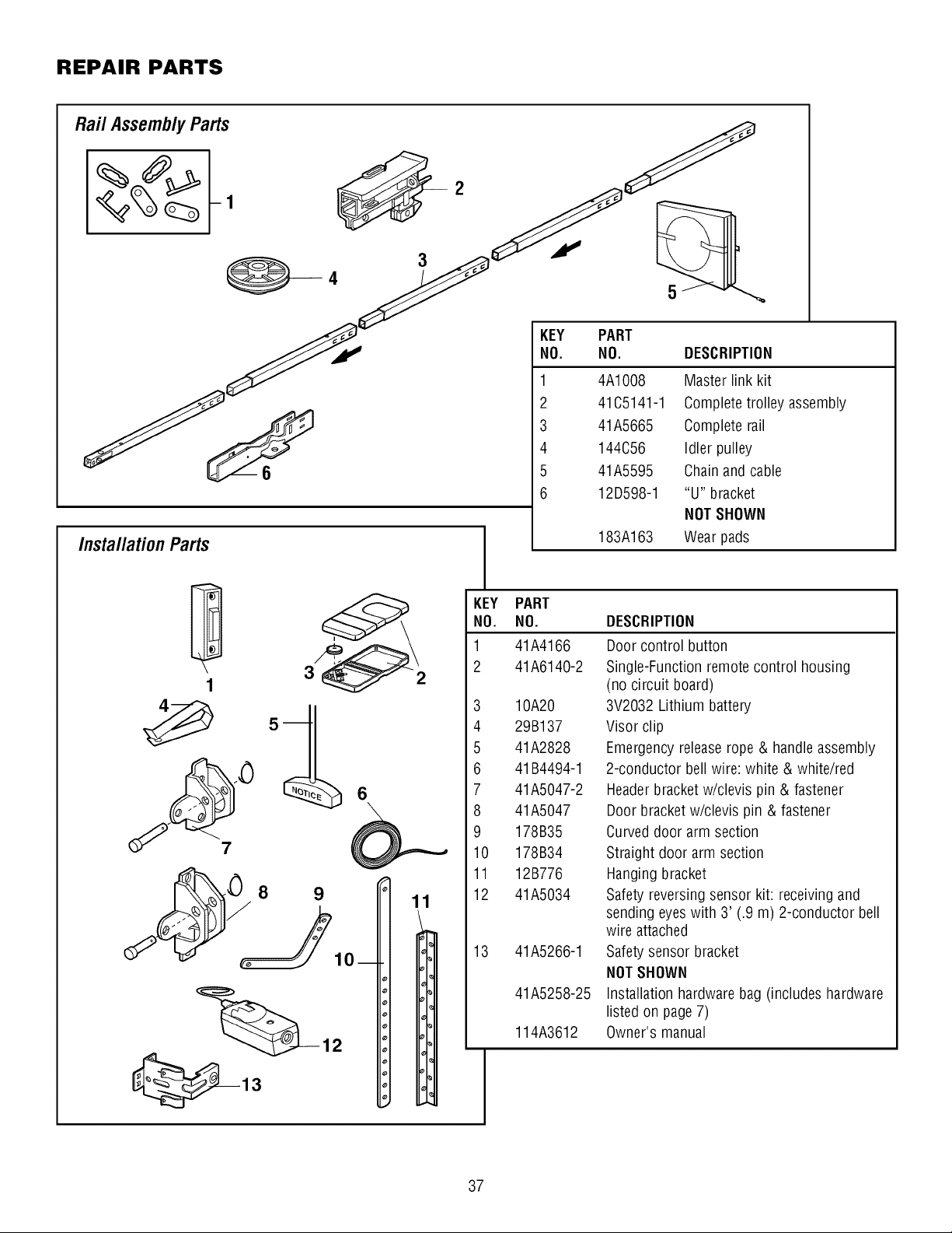
REPAIR PARTS
3 41A5665 Complete rail
4 144C56 Idler pulley
5 41A5595 Chain and cable
6 12D598-1 "U" bracket
NOTSHOWN
InstallationParts 183A163 Wear pads
D
1
6
11
KEY PART
NO. NO.
1 41A4166
2 41A6140-2
3 10A20
4 29B137
5 41A2828
6 41 B4494-1
7 41A5047-2
8 41A5047
9 178B35
10 178B34
11 12B776
12 41A5034
13 41A5266-1
41A5258-25
114A3612
DESCRIPTION
Door control button
Single-Function remote control housing
(no circuit board)
3V2032 Lithium battery
Visor clip
Emergency releaserope & handle assembly
2-conductor bell wire: white & white/red
Headerbracket w/clevis pin & fastener
Door bracket w/clevis pin & fastener
Curveddoor arm section
Straight door arm section
Hanging bracket
Safety reversing sensor kit: receivingand
sending eyes with 3' (.9 m) 2-conductor bell
wire attached
Safety sensor bracket
NOTSHOWN
Installation hardware bag (includes hardware
listed on page 7)
Owner's manual
37
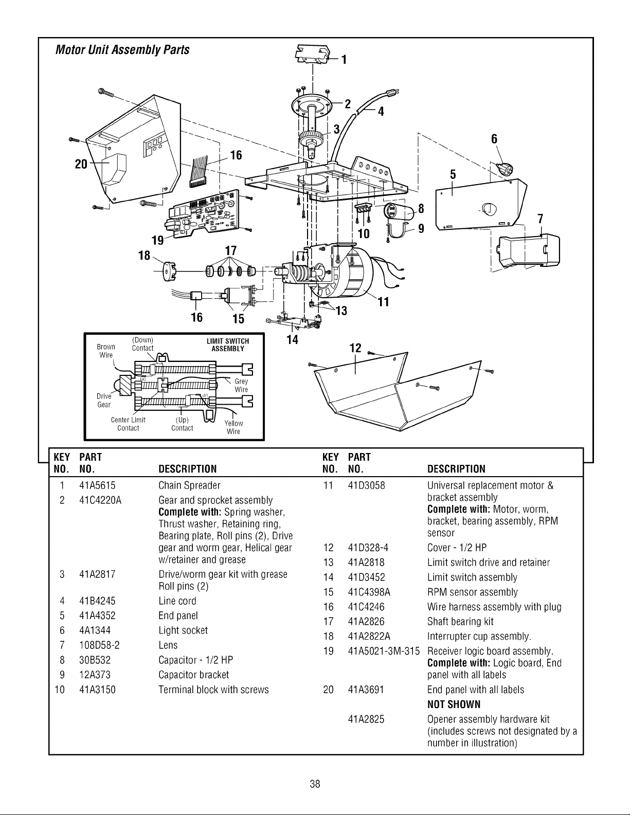
Motor Unit Assembly Parts
19
18 17
4
I
I 5
7
16 15
(Down) LIMIT SWITCH
Brown Contact ASSEMBLY
Wire \/"'_
\
Gr_
_4"--.",L _ ................ _t' Wire
Drive _ - / t d,
Gear _J_ffllf_/fffff_
CenterL:imit (Up) L,',,',,',,',,',,',_JYellow
contact contact wire
14
12
KEY
NO.
1
2
4
5
6
7
8
9
10
PART
NO.
41A5615
41C4220A
41A2817
41B4245
41A4352
4A1344
108D58-2
30B532
12A373
41A3150
KEY PART
DESCRIPTION NO. NO. DESCRIPTION
Chain Spreader 11 41D3058
Gearand sprocket assembly
Completewith: Spring washer,
Thrust washer, Retainingring,
Bearingplate, Roll pins (2), Drive
gear andworm gear, Helical gear 12
w/retainer and grease 13
Drive/worm gear kit with grease 14
41D328-4
41A2818
41D3452
Universal replacementmotor &
bracket assembly
Complete with: Motor, worm,
bracket, bearing assembly, RPM
sensor
Cover- 1/2 HP
Limit switch drive and retainer
Limit switch assembly
Roll pins (2) 15 41C4398A
Line cord 16 41C4246
End panel 17 41A2826
Light socket
18 41A2822A
Lens 19 41A5021-3M-315
Capacitor- 1/2 HP
Capacitor bracket
Terminal blockwith screws 20 41A3691
41A2825
RPM sensor assembly
Wire harnessassembly with plug
Shaft bearing kit
Interrupter cup assembly.
Receiverlogic board assembly.
Completewith: Logic board, End
panelwith all labels
End panelwith all labels
NOTSHOWN
Openerassembly hardware kit
(includes screws not designated by a
number in illustration)
38
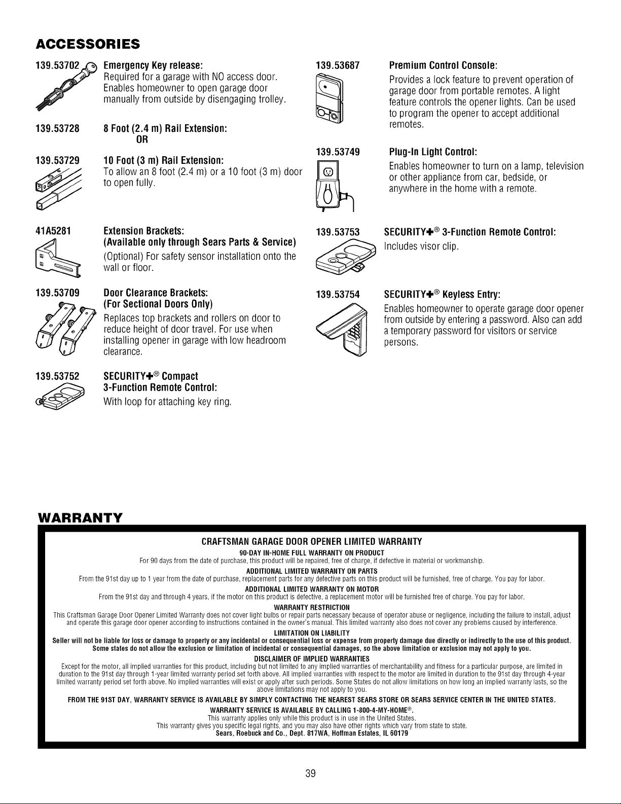
ACCESSORIES
7
139.53728
139.53729
EmergencyKeyrelease:
Required for a garagewith NOaccessdoor.
Enableshomeowner to open garage door
manually from outside by disengaging trolley.
8 Foot (2.4 m) Rail Extension:
OR
10 Foot (3 m) Rail Extension:
To allow an 8 foot (2.4 m) or a 10 foot (3 m) door
to open fully.
41A5281
139.53709
ExtensionBrackets:
(Available onlythroughSears Parts & Service)
(Optional) For safety sensor installation onto the
wall or floor.
DoorClearance Brackets:
(For SectionalDoorsOnly)
Replacestop brackets and rollers on door to
reduce height of door travel. For use when
installing opener in garagewith low headroom
clearance.
139.53752
SECURITY+® Compact
3-FunctionRemoteControl:
With loop for attaching key ring.
139.53687
139.53749
139.53753
139.53754
Premium ControlConsole:
Providesa lock feature to preventoperation of
garagedoor from portable remotes.A light
feature controls the opener lights. Canbe used
to program the opener to accept additional
remotes.
Plug-In LightControl:
Enableshomeowner to turn on a lamp, television
or other appliancefrom car, bedside,or
anywhere in the home with a remote.
SECURITY+® 3-FunctionRemoteControl:
Includes visor clip.
SECURITY,I,® KeylessEntry:
Enableshomeownerto operate garagedoor opener
from outside by entering a password. Also can add
a temporary password for visitors or service
persons.
WARRANTY
CRAFTSMANGARAGEDOOROPENERLIMITEDWARRANTY
90-DAY IN-HOME FULL WARRANTY ON PRODUCT
For 90 days from the date of purchase, this product will be repaired, free of charge, if defective in material or workmanship.
ADDITIONAL LIMITED WARRANTY ON PARTS
From the 91st day up to 1 year from the date of purchase, replacement parts for any defective parts on this product will be furnished, free of charge. You pay for labor.
ADDITIONAL LIMITED WARRANTY ON MOTOR
From the 91st day and through 4 years, if the motor on this product is defective, a replacement motor will be furnished free of charge. You pay for labor.
WARRANTY RESTRICTION
This Craftsman Garage Door Opener Limited Warranty does not cover light bulbs or repair parts necessary because of operator abuse or negligence, including the failure to install, adjust
and operate this garage door opener according to instructions contained in the owner's manual. This limited warranty also does not cover any problems caused by interference.
LIMITATION ON LIABILITY
Seller will notbe liable for loss or damage to property or any incidental or consequential loss or expense from property damage due directly or indirectly to the use of this product.
Some states do notallow the exclusion or limitation of incidental or consequential damages, so the above limitation or exclusion may notapply to you.
DISCLAIMER OF IMPLIED WARRANTIES
Except for the motor, all implied warranties for this product, including but not limited to any implied warranties of merchantability and fitness for a particular purpose, are limited in
duration to the 91st day through 1-year limited warranty period set forth above. All implied warranties with respect to the motor are limited in duration to the 91st day through 4-year
limited warranty period set forth above. No implied warranties will exist or apply after such periods. Some States do not allow limitations on how long an implied warranty lasts, so the
above limitations may not apply to you.
FROM THE 91ST DAY, WARRANTY SERVICEIS AVAILABLEBY SIMPLY CONTACTINGTHE NEAREST SEARSSTORE OR SEARSSERVICE CENTERIN THE UNITED STATES.
WARRANTY SERVICE IS AVAILABLEBYCALLING 1-800-4-MY-HOME ®.
This warranty applies only while this product is in use in the United States.
This warranty gives you specific legal rights, and you may also have other rights which vary from state to state.
Sears, Roebuck and Co., Dept. 817WA, Hoffman Estates, IL 60179
39
CONTENIDO
Introducci6n 2-7
Revisi6n de los simbolos y t_rminos de seguridad ................. 2
Preparaci6n de la puerta de su cochera .......................... 3
Herramientas necesarias...................................... 3
Planificaci6n ............................................. 4-5
Inventario de la caja de cart6n ................................. 6
Inventario de piezas ......................................... 7
Montaje 8-11
Monte el riel y instale el trole .................................. 8
Fije el riel al motor e instale la polea Ioca......................... 9
Instale la cadena y cable .................................... 10
Apriete la cadena .......................................... 11
Instalaci6n 11-26
Instrucci6nes de seguridad para la instalaci6n.................... 11
Determine d6nde va a instalar
la m_nsula del cabezal ...................................... 12
Instale la m_nsula del cabezal................................. 13
Coloque el riel en la m_nsula del cabezal........................ 14
Coloque el abridor en posici6n ................................ 15
Cuelgue el abridor .......................................... 16
Instale la unidad de control de la puerta......................... 17
Instale las luces ........................................... 18
Instale la manija y la cuerda de emergencia ...................... 18
Requisitos para la instalaci6n el_ctrica .......................... 19
Instale el Sistema de Protecci6n® ........................... 20-22
Fije la m_nsula de la puerta ................................ 23-24
Conecte el brazo de la puerta al trole ......................... 25-26
Ajustes 27-29
Ajuste el limite del recorrido .................................. 27
Ajuste lafuerza ............................................ 28
Pruebe el sistema de retroceso de seguridad..................... 29
Pruebe el Sistema de Protecci6n® ............................. 29
Operaci6n 30-34
Instrucci6nes de seguridad para la operaci6n .................... 30
C6mo usar su abridor de puerta de cochera...................... 30
C6mo usar la unidad de control de pared........................ 31
C6mo abrir la puerta manualmente ............................ 31
Mantenimiento de su abridor de puerta de cochera ................ 32
Si tiene alg_n problema ..................................... 33
Tabla de diagndstico ........................................ 34
C#mo Programar el Abridor 35-36
C6mo agregar o reprogramar un
control remoto manual ...................................... 35
Para borrar todos los cddigos de la memoria
de la unidad del motor ...................................... 35
Controles remotos de 3 funciones ............................. 35
Cdmo agregar, reprogramar o cambiar un
cddigo de entrada sin Ilave................................... 36
Accesorios 37
Garantia 37
N#meros de Servicio
Contratapa
INTRODUCCION
Revisi6nde los simbolosy t_rminosde seguridad
Este abridor de puerta de cochera ha sido diseSado y probado para un funcionamiento seguro, siempre y cuando se instale, se pruebe, se opere y se le
d_ mantenimiento como se indica en este manual, cumpliendo al pie de la letra con todas las advertencias e instrucciones generalesaqui contenidas.
Mecanica
El_ctrica
Estas advertencias y/o simbolos de seguridad que aparecenen este
manual le alertar_.nde que existe el riesgo de una lesi6n seria e de
muerte si no se siguen las instrucciones correspondientes. El peligro
puede ser el_ctrico (electrocuci6n) o mec_.nico.Lea las instrucciones
con mucho cuidado.
Cuandovea esta palabray/o simbolo de seguridad eneste manual, le
alertar_,de que existeel riesgo de da_ar la puerta de la cochera y/o el
abridor si no se siguen las instrucciones correspondientes. Lealas
instrucciones con mucho cuidado.
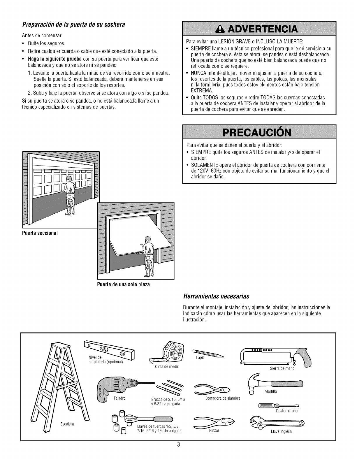
Preparaci6nde la puerta de su cochera
Antes de comenzar:
• Quite los seguros.
• Retire cualquier cuerda o cableque est_conectado a la puerta.
• Haga la siguienteprueba con su puerta para verificar que est_
balanceaday que no se atore ni se pandee:
1. Levante la puerta hasta la mitad de su recorrido como se muestra.
Suelte la puerta. Si est,. balanceada,deber_,mantenerseen esa
posici6n con s61oel soporte de los resortes.
2. Suba y bajela puerta; observe si se atora con algo o si se pandea.
Si su puerta seatora o se pandea, o no est,. balanceadaIlamea un
t@nico especializadoen sistemas de puertas.
Para evitar una LESIONGRAVEo INCLUSOLA MUERTE:
• SIEMPRE Ilamea un t_cnico profesional para que le d_ servicio a su
puerta de cochera si _sta se atora, se pandeao est,. desbalanceada.
Una puerta de cochera que no est_ bien balanceadapuede que no
retroceda como se requiere.
• NUNCAintente aflojar, mover ni ajustar la puerta de su cochera,
los resortes de la puerta, los cables, las poleas, las m_nsulas
ni latornilleria, pues todos estos elementos est_.nbajo tensi6n
EXTREMA.
• Quite TODOSlos seguros y retire TODASlas cuerdas conectadas
a la puerta de cochera ANTESde instalar y operar el abridor de la
puerta de cochera paraevitar que se enreden.
Para evitar que se da_en el puerta y el abridor:
• SIEMPREquite los seguros ANTESde instalar y/o de operar el
abridor.
• SOLAMENTEopere el abridor de puerta de cochera con corriente
de 120V,60Hz con objeto de evitar su malfuncionamiento y que el
abridor se da_e.
Puertaseccional
Puertade unasolapieza
Herramientasnecesarias
Durante el montaje, instalaci6n y ajuste del abridor, las instrucciones le
indicar_.nc6mo usar las herramientas queaparecen en la siguiente
ilustraci6n.
carpinteria (opcional)
Cinta de medir
Sierra de mano
Escalera
Taladro
Brocas de 3/16, 5/16
y 5/32 de pulgada
8
8
Cortadora de alambre
Pinzas
Martillo
Destornillador
Llaveinglesa
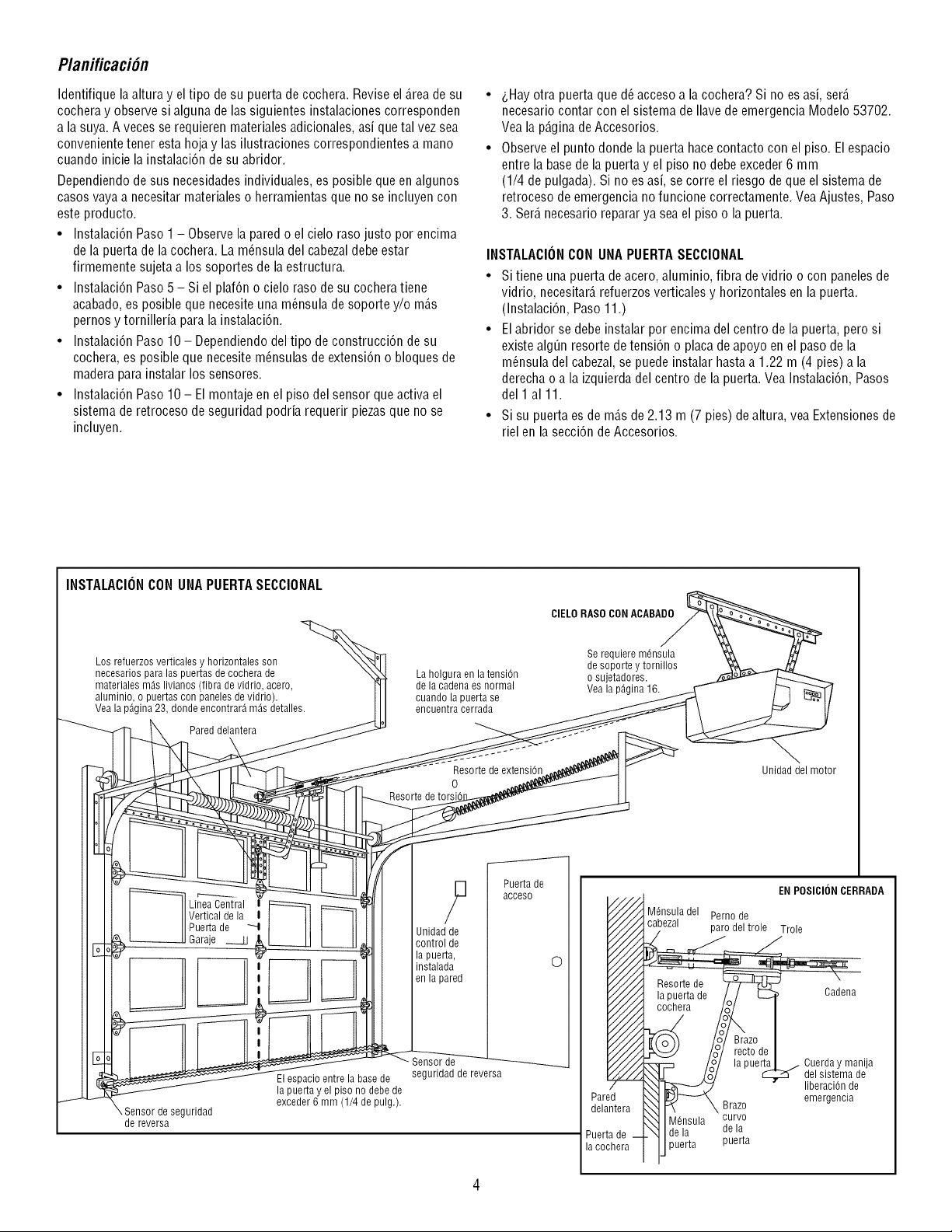
Planificaci6n
Identifique laaltura y el tipo de su puerta de cochera. Reviseel _.reade su
cochera y observe si alguna de las siguientes instalaciones corresponden
a la suya. A veces se requieren materiales adicionales, asi quetal vez sea
convenientetener esta hojay las ilustraciones correspondientes a mano
cuando inicie la instalaci6n de su abridor.
Dependiendode sus necesidadesindividuales, es posible que en algunos
casos vaya a necesitar materiales o herramientas que no se incluyen con
este producto.
• Instalaci6n Paso 1 - Observela pared o el cielo raso justo por encima
de la puerta de lacochera. La m_nsula del cabezaldebe estar
firmemente sujeta a los soportes de la estructura.
• Instalaci6n Paso5 - Si el plaf6n o cielo raso de su cochera tiene
acabado, es posible que necesite una m_nsula de soporte y/o m_.s
pernos y tornilleria para la instalaci6n.
• Instalaci6n Paso 10 - Dependiendodel tipo de construcci6n de su
cochera, es posible que necesite m_nsulas de extensi6n o bloques de
madera parainstalar los sensores.
• Instalaci6n Paso 10 - Elmontaje en el piso del sensor que activa el
sistema de retroceso de seguridad podria requerir piezasque no se
incluyen.
_,Hayotra puerta que d_ acceso a la cochera? Si no es asi, ser_.
necesario contar con el sistema de Ilave de emergencia Modelo 53702.
Vea la p_.ginadeAccesorios.
Observe el punto donde la puerta hace contacto con el piso. El espacio
entre la base de la puerta y el piso no debe exceder 6 mm
(1/4 de pulgada). Si no es asi, se corre el riesgo de que el sistema de
retroceso de emergencia no funcione correctamente. VeaAjustes, Paso
3. Ser_.necesario reparar ya sea el piso o la puerta.
INSTALACIONCON UNA PUERTASECCIONAL
• Si tiene una puerta de acero, aluminio, fibra de vidrio o con panelesde
vidrio, necesitar_,refuerzos verticales y horizontales en la puerta.
(Instalaci6n, Paso11.)
• Elabridor se debe instalar por encima del centro de la puerta, pero si
existe alg_n resorte de tensi6n o placa deapoyo en el paso de la
m_nsula del cabezal, se puede instalar hasta a 1.22 m (4 pies) a la
derecha o a la izquierda del centro dela puerta. Vea Instalaci6n, Pasos
del 1 a111.
• Si su puerta es de m_.sde 2.13 m (7 pies) dealtura, vea Extensiones de
riel en la secci6n de Accesorios.
INSTALACIONCON UNAPUERTASECCIONAL
Los refuerzos verticales y horizontales son
necesarios para las puertas de cochera de
materiales m_s livianos (1ibra de vidrio, acero,
aluminio, o puertas con paneles de vidrio).
Vea la p_gina 23, donde encontrar_ m_s detalles.
I IIVertical de la t iI
! IIPuerta de _1
, _Garaje ___U
_J l __ El espacio entre la base de
la puerta y el piso no debe de
exceder 6 mm (1/4 de pulg.).
Sensor de seguridad
de reversa
La holgura en la tension
de la cadena es normal
cuando la puerta se
encuentra cerrada
Resorte de extension
0
Resorte de torsi(
9
Unidad de
control de
la puerta,
instalada
en la pared
Puerta de
acceso
CIELORASOCON ACABA_
Se requiere m6nsula '_ _/
de soporte y tornillos ' [_
o sujetadores.
Vea la pAgina 16.
._ Unidad del motor
O
Sensorde
seguridad de reversa
EN POSICIONCERRADA
Mdnsuladel Perno de
cabezal
parodeltrole Trole
Cadena
Brazo
M6nsula curvo
de la de la
puerta puerta
Cuerda y manija
del sistema de
liberaciOn de
emergencia
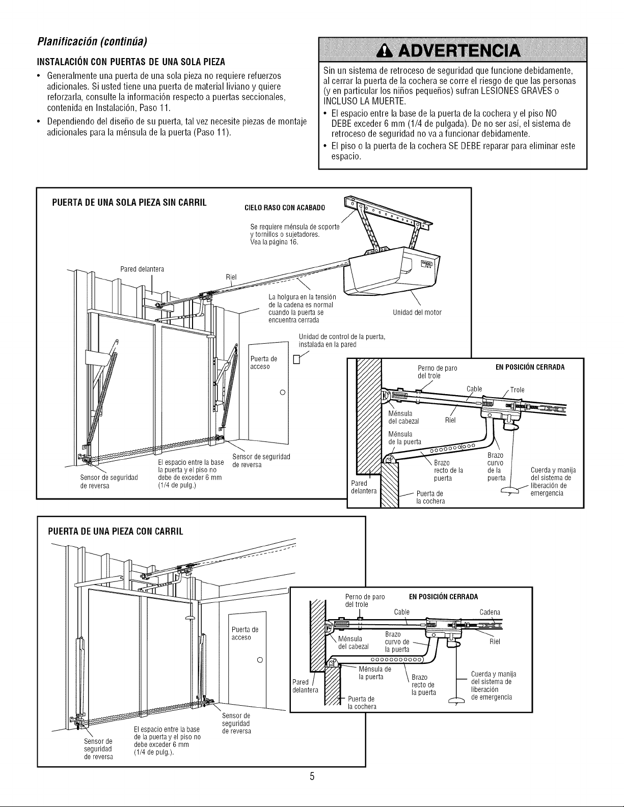
Planificaci6n(contin#a)
INSTALACIONCON PUERTASDE UNASOLAPIEZA
• Generalmenteuna puerta de una sola pieza no requiere refuerzos
adicionales. Si usted tiene una puerta de material liviano y quiere
reforzarla, consulte la informacidn respecto a puertas seccionales,
contenida en Instalacien, Paso11.
• Dependiendo del dise_o de su puerta, tal vet necesite piezasde montaje
adicionales para la m_nsula de la puerta (Paso 11).
Sin un sistema de retroceso de seguridad que funcione debidamente,
al cerrar la puerta de la cochera se corre el riesgo de que las personas
(yen particular los ni_os peque_os)sufran LESIONESGRAVESo
INCLUSOLA MUERTE.
• El espacio entre la basede la puerta de la cochera y el piso NO
DEBEexceder 6 mm (1/4 de pulgada). Deno serasi, el sistema de
retroceso de seguridad no va a funcionar debidamente.
• El piso o la puerta de la cochera SE DEBEreparar para eliminar este
espacio.
PUERTADE UNASOLAPIEZASIN CARRIL CIELORASOCONACABADO
Serequieremensuladesoporte '_ _'},_,z.._
y tornilloso sujetadores. _ j_/
Vealap_gina 16.
J_df ¢q _-----Y7
_,..._ Zared delantera Rie, ___'_-h /P _ -°i/
_ r
III1 - 111 o ooo*r orr
Ill / 9 I -_W_II I Unidaddecontroldela puerta,
I Iill
_ U
_r_/_ I IIM_iIII_cc_;o_I" I1_/_ Pernodeparo ENPOSICIONCERRADA
IIIkdl_ l Ill'Ill I I I _//--/_ del_ole
_ i IIIII I_m I I ,-,I I I//././/_ Cable ,Trole
"-'_e seguridad I IP"//.//"/I_ Brazo
_ El espacio entrelabase dereversa F/_ _°o
/ _ la puerta y elpiso no I _N'] rectodela dela Cuerday manija
Sensordeseguridad debedeexceder6 mm _,'m-r_l_N_._ puerta puerta delsistemade
dereversa (1/4 de pulg.) P',a,rea, JN_] ..-- _ liberaciende
aelan[era JN_'_J./1 Puertade _ -q emergencia
I _\_1 Iacochera
PUERTADE UNA PIEZACON CARRIL
\
Sensor de
seguridad
de reversa
li acceso C
II IJll I I Pared
_-J_---_____.__ . Sensorde .-______.delantera
seguridad
El espacio entrelabase dereversa
delapuerta y elpiso no
debeexceder6 mm
(1/4 de pulg.).
Perno de paro EN POSICI()N CERRADA
del trole
Cable Cadena
Riel
la puerta Brazo Cuerda y manija
recto de del sistema de
la puerta liberaciOn
Puerta de de emergencia
la cochera

Inventario de la Cajade Cart6n
Su abridor viene empacado en una caja de cart6n que contiene el motor y
las piezasque se muestran en la siguiente ilustraci6n. Tome nota de que
los accesorios depender_.ndel modelo que haya comprado. Sifalta
alguna pieza, revise con cuidado el material de empaque ya que en
ocasiones las piezasse atoran en el mismo. Toda la tornilleria y las
piezas necesarias para el montaje e instalaci6n de su puerta se ilustran en
la siguiente p_.gina.Conserve la caja y los materiales de empaque hasta
que la instalaci6n y el ajuste se hayanterminado.
Bot6nde control de la puerta
SECURITY÷®
Controlremoto detres funciones
@
Poleade lacadena
Cadenay cable
Secci6ndelantera
del riel (cabezal)
Unidad del motorcon uno lente
Mensuladel eabezal
Seccionescentral
y posterior del riel
Mensula de la puerta
Trole
Secci6ncurva del
brazode la puerta
Dos cables conductores
de campana. Blancoy blanco/rojo
Desplegadorde Cadena
% °h
@I _I _
% %
Io %
% %
% %
Mensulaspara colgar
Mensulaspara el sensor del sistema
de retrocesode seguridad(2)
ProtectorSystem®
Dossensoresdel sistemade
retrocesode seguridad (un ojo transmisor
y un ojo receptor) conectadosa uncable
de campana de dos conductores.
Blancoy blancoy negro
Etiquetasde
seguridady
literatura
Secci6nrecta
del brazo de
la puerta

Inventario de Piezas
Antes de la instalaci6n, organice todas las piezas en grupos como se muestra en la siguiente ilustraci6n.
TORNILLERIAY PIEZASPARAELMONTAJE
Tuercade Arandela 5/8pulg. (2) Arandela de Tuercade
1/4-20 (2) 3/8 pulg. (1) 3/8 pulg.(1)
Perno de
1/4-20xl-3/4 pulg. (1)
Perno de 1/4-20x2-1/2de pulg.(1)
[©
Flecha roscada del trole (1)
i i
Enlaeemaestro(2)
Separador(2)
PernoIoco (1)
TORNILLERIAY PIEZASPARALAINSTALACION
Perno deeoche
de 1/4-20xl/2 pulg. (2)
Tuercade mariposa
1/4-20pulg. (2)
Tornillode cabeza cuadrada
de 5/16-9xl-5/8 de pulg. (2)
de 5/16-18xl-7/8 pulg.(2)
O
Anillo sujetador(3) Tuereade Manija
8/16-18 pulg.(6)
r D
Pernohexagonal Grapa con
de 5/16-18x7/8pulg. (4) Arandelade 5/16pulg. (5) aislamiento(30)
_ lllllllllllllllllMlllllll_
Tornillo6ABx1-1/4 pulg.(2)
_oscante
de 1/4-14x5/8 de pulg.(2)
Pasadordechaveta
de 5/16x1-1/2 pulg.(1)
Taquetepara murofalso (2)
_ IIIIIIIIIIIIIIIIIIIII
Tornillode 6-32xl pulg. (2)
6AB x 1-1/2 pulg.
°D ol
Pasadorde chaveta Pasador de chaveta
de 5/16x1-1/4pulg. (1) de 5/16xl pulg. (1)
Cuerda
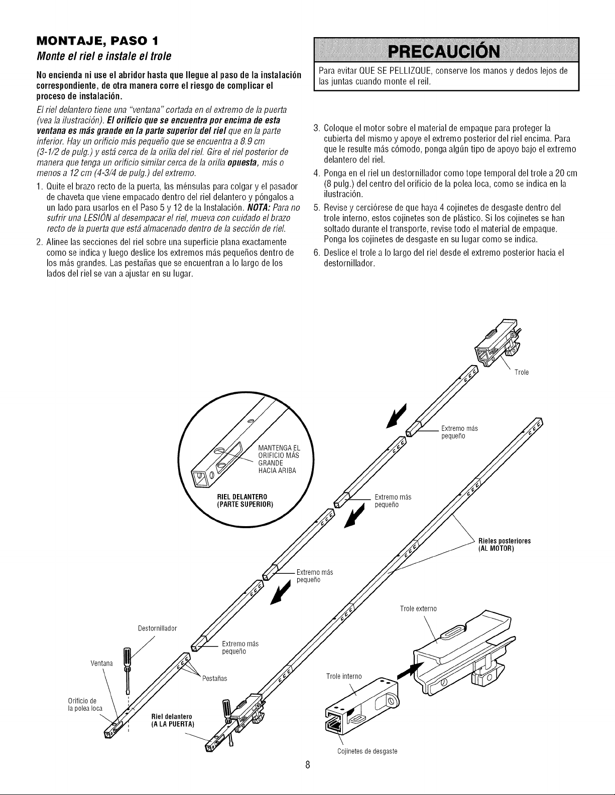
MONTAJE, PASO 1
Monte e/fie/e insta/e e/tro/e
No encienda ni use el abridorhasta que Ilegue al paso de la instalaci6n
correspondiente,de otra manera correel riesgo de complicar el
proceso de instalaci6n.
El riel delaiTterotieiTeuiTa"veiTtaiTa"cortada ei7el extremo de la puerta
(vea la ilustracibn). El orificioque se encuentrapor encima de esta
ventana es mbs grande en /a parte superior de/fie/que en /aparte
inferior. Hay un orificio m_s pequeffo que se encuentra a 8.9 cm
(3-1/2 de pulg.) y est_cerca de la orilla del rieL Gire el riel posterior de
manera que tenga un orificio similar cerca de la orilla opuesta, m_s o
menos a 12 cm (4-3/4 de pulg.) del extremo.
1. Quite el brazo recto de la puerta, las m_nsulas para colgar y el pasador
de chavetaque viene empacado dentro del riel delantero y p6ngalos a
un lado para usarlos en el Paso5 y 12 de la Instalaci6n. NOTA:Parano
sufrir una LESIONal desempacar el riel, mueva con cuidado el brazo
recto de la puerta que est_ almacenado dentro de la secci6n de rieL
2. Alinee las secciones del riel sobre una superficie plana exactamente
como se indica y luego deslice los extremos m_.spequefios dentro de
los m_.sgrandes. Las pestafiasque se encuentran a Io largo de los
lados del riel se van a ajustar en su lugar.
Para evitar QUESE PELLIZQUE,conserve los manos y dedos lejos de
las juntas cuando monte el reil.
3. Coloque el motor sobre el material de empaque para proteger la
cubierta del mismo y apoye el extremo posterior del riel encima. Para
que le resulte m_.sc6modo, pongaalg_n tipo de apoyo bajo el extremo
delantero del riel.
4. Ponga en el riel un destornillador como tope temporal del trole a 20 cm
(8 pulg.) del centro del orificio de la polea Ioca, como se indica en la
ilustraci6n.
5. Revise y cerci6rese deque haya4 cojinetes de desgastedentro del
trole interno, estos cojinetes son de pl_.stico.Si los cojinetes se han
soltado durante el transporte, revisetodo el material de empaque.
Ponga los cojinetes de desgaste en su lugar como se indica.
6. Deslice el trole a Io largo del riel desde el extremo posterior haciael
destornillador.
__ Extremom_s
pequefio
Extremom_s
peque_o
Trole
Rieles posteriores
(AL MOTOR)
Extremom_s
peque_o
Ventana
Orificio de
la polea Ioca
Destornillador
Riel delantero
(A LA PUERTA)
Pesta_as
Extremom_s
peque_o
Trole externo
Trole interno
Cojinetes de desgaste
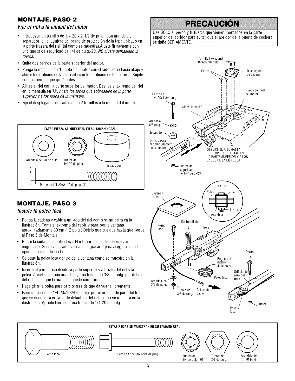
MONTAJE, PASO 2
Fije el riel a la unidadde/motor
• Introduzca un tornillo de 1/4-20 x 2-1/2 de pulg., con arandela y
separador, en el agujero del perno de protecci6n de latapa ubicado en
la parte trasera del riel (tal como se muestra).Ajuste firmemente con
una tuerca de seguridad de 1/4 de pulg.-20. NOajuste demasiado la
tuerca.
• Quite dos pernos de la parte superior del motor.
• Ponga la m_nsula en 'U' sobre el motor con el lado piano haciaabajo y
alinee los orificios de la m_nsulacon los orificios de los pernos. Sujete
con los pernos que quit6 antes.
• Alinee el riel con la parte superior del motor. Desliceel extremo del riel
en la m_nsula en 'U', hasta los topes que sobresalenen la parte
superior y a los lados de la m#nsula.
• Fije el desplegador de cadenacon 2 tornillos a la unidad del motor.
ESTASPIEZASSE MUESTRAN EN SU TAMA_IOREAL
@
Arandela de 5/8 de pulg. Tuerca de
1/4-20 de pulg.
U
Pernode1/4-20x2-1/2de pulg.(1)
Espaciador
MONTAJE, PASO 3
Instale la polea Ioca
• Pongala cadenay cable a un lado del riel como se muestra en la
ilustraci6n. Tome el extremo del cabley pase por laventana
aproximadamente 30 cm (12 pulg.) D_jelo que cuelgue hasta que Ileque
al Paso5 de Montaje.
• Retire la cinta de la polea Ioca. El interior del centro debe estar
engrasado. Si se ha secado, vuelva a engrasarlo para asegurar que la
operaci6n seaadecuada.
• Coloque la polea Ioca dentro de la ventana como se muestra en la
ilustraci6n.
• Inserte el perno Ioco desde la parte superior y a trav_s del riel y la
polea.Apriete con unaarandelay una tuerca de 3/8 de pulg. por debajo
del riel hastaque la arandelaquede comprimida.
• Hagagirar la polea para cerciorarse de que da vuelta libremente.
• Paseun perno de 1/4-20xl-3/4 de pulg. por el orificio de paro del trole
que se encuentra en la parte delantera del riel, como se muestra en la
ilustraci6n. Apriete bien con unatuerca de 1/4-20 de pulg.
Use SOLOel perno y la tuerca que vienen montados en la parte
superior del abridor para evitar que el abridor de la puerta de cochera
se da_e SERIAMENTE.
Tornillo Hexagonal
8-32x7/16 pulg. --._
Perno _._ Desplegador
decadena
I
Rueda dentada
Perno de _ del motor
I
1/4-20xl-3/4 pulg II II /
M6nsula en 'U'
Arandela ! ____
/
Orificio para , _" /'\\\_L_Jg._ ,_ \ "_"_-'-_ /
el perno protecto I//._/,_ I -"JP" X%"_ " \\ /
de,acu ,erta / y fHA, T"OES,,OE-- A "
_//- _lli I-- %
/// /_,JlV LOS TOPESQUE ESTAN EN
// / " LA PARTE SUPERIOR Y A LOS
/- ', LADOS DELA MENSULA
_-- Tuerca de
seguridad
de 1/4" pulg.-20
Cadena y
cable
Perno
Destornillador
Perno
Arandela
Trole
Perno
Engraseel
interior
_de lapolea
Orificio dc //
_ paro del
A.nde,de o.o.
_Ceapduelg_a%1_ed
-- / i_..tueroa
Polea /
Ioca
Pernoloco
ESTAS PIEZASSE MUESTRAN ENSU TAMA_IOREAL
Perno de 1/4-20xl-3/4 de pulg.
@
Tuerca de
1/4 de pulg.-20
Tuerca de
3/8 de pulg.
Arandela de
3/8 de pulg.
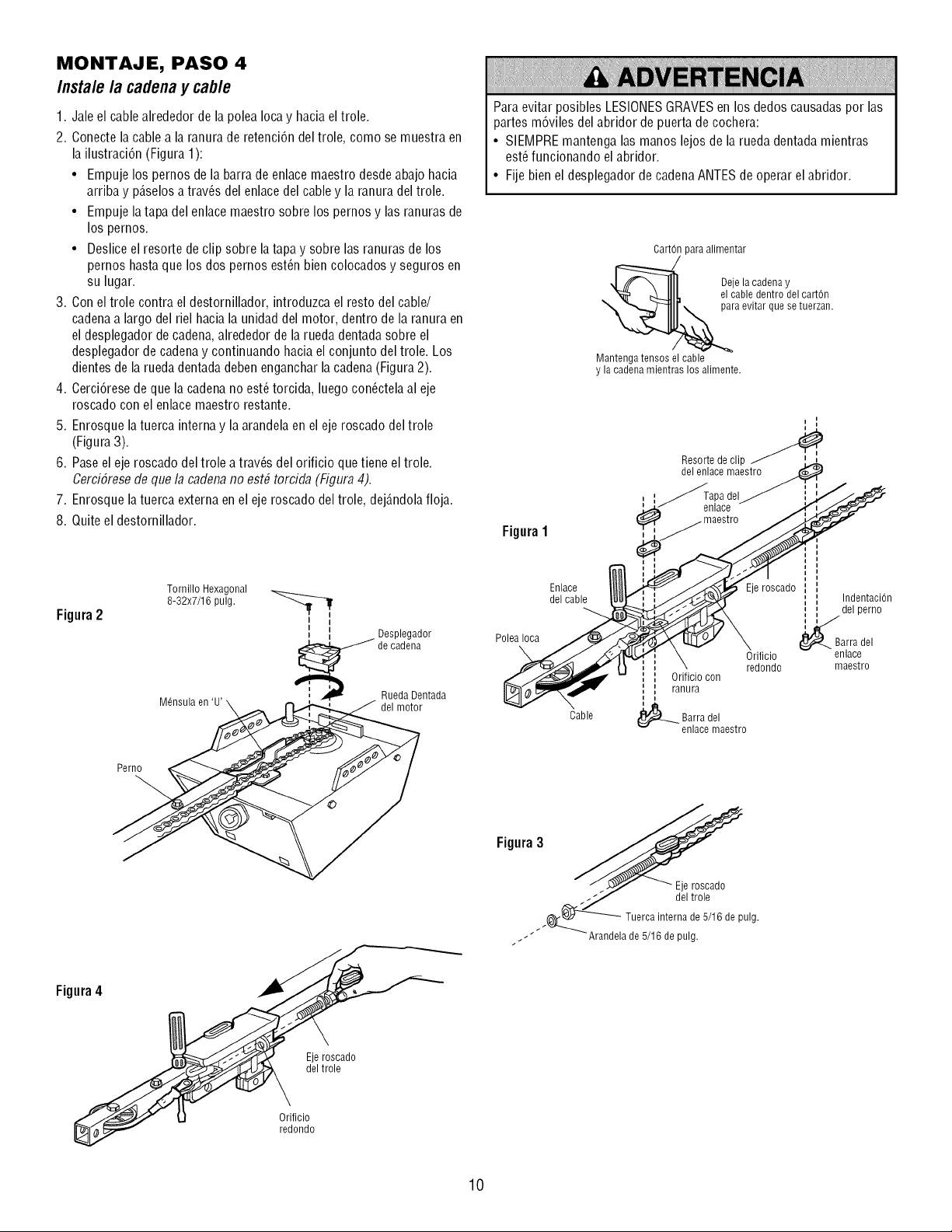
MONTAJE, PASO 4
Instale la cadenay cab/e
1. Jale el cablealrededor de la polea Ioca y hacia el trole.
2. Conecte la cable a la ranura de retenci6n del trole, como se muestra en
la ilustraci6n (Figura 1):
• Empuje los pernos de la barra de enlace maestro desde abajo hacia
arriba y p_.selosa trav_s del enlace del cable y la ranura del trole.
• Empuje latapa del enlace maestro sobre los pernos y las ranuras de
los pernos.
• Deslice el resorte de clip sobre la tapa y sobre las ranuras de los
pernos hasta que los dos pernos est_n bien colocados y seguros en
su lugar.
3. Con el trole contra el destornillador, introduzca el resto del cable/
cadenaa largo del riel hacia la unidad del motor, dentro de la ranura en
el desplegador de cadena,alrededor de la rueda dentada sobre el
desplegador decadenay continuando hacia el conjunto del trole. Los
dientes de la rueda dentada deben engancharla cadena(Figura 2).
4. Cerci6rese de que la cadenano est_ torcida, luego con_ctelaal eje
roscado con el enlace maestro restante.
5. Enrosque la tuerca interna y la arandela en el eje roscado del trole
(Figura 3).
6. Paseel eje roscado del trole a trav_s del orificio que tiene el trole.
Cerci6resede que la cadena no est# torcida (Figura4).
7. Enrosque la tuerca externa en el eje roscado del trole, dej_.ndolafloja.
8. Quite el destornillador.
Para evitar posibles LESIONESGRAVESen los dedos causadaspor las
partes m6viles del abridor de puerta de cochera:
• SIEMPREmantenga las manos lejos de la rueda dentada mientras
est_funcionando el abridor.
• Fije bienel desplegador de cadenaANTESde operar el abridor.
CartOnpara alimentar
Deje la cadena y
el cable dentro del carton
para evitar que se tuerzan.
Mantenga tensos el cable
y la cadena mientras los alimente.
Resorte de clip
del enlace maestro
Figura1
Figura2
Tornillo Hexagonal
8-32x7/16 pulg.
I I
I I
! _ Desplegador
de cadena
Rueda Dentada
del motor
PoleaIoca
\
Enlace
del cable
Cable
Orificio
redondo
', Orificio con
,, ranura
_ garra del
enlace maestro
Eje roscado
IndentaciOn
del perno
l_Barra del
enlace
maestro
Perno
Figura3
Eje roscado
deltrole
._ Tuerca interna de 5/16 de pulg.
.. Arandela de 5/16 de pulg.
Figura4
Eje roscado
del trole
Orificio
redondo
10
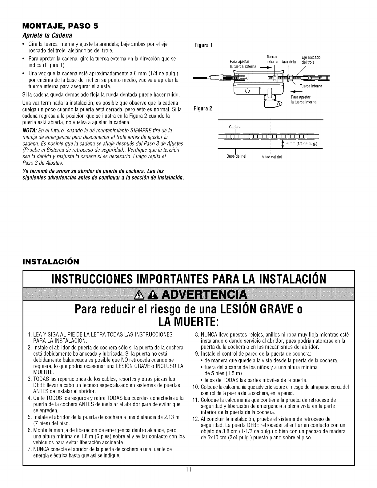
MONTAJE, PASO 5
Apriete la Cadena
• Gire la tuerca interna y ajuste la arandela; baje ambas por el eje
roscado del trole, alej_.ndolasdel trole.
• Para apretar la cadena, gire la tuerca externa en la direcci6n que se
indica (Figura 1).
• Una vez que la cadena est_ aproximadamente a 6 mm (1/4 de pulg.)
por encima de la base del riel en su punto medio, vuelva a apretar la
tuerca interna para asegurar el ajuste.
Si la cadenaqueda demasiado floja la rueda dentadapuede hacer ruido.
Una vez terminada la instalaci6n, es posible que observe que la cadena
cuelga un poco cuando la puerta est,. cerrada, pero esto es normal. Si la
cadena regresa a la posici6n que se ilustra en la Figura 2 cuando la
puerta est,. abierta, no vuelva a ajustar la cadena.
NOTA:En el futuro, cuando le d# mantenimiento SIEMPRE tire de la
manija de emergencb para desconectar el trole antes de ajustar la
cadena. Es posible que la cadenase afloje despu#s del Paso 3 de Ajustes
(Pruebe el Sbtema de retroceso de seguridad). Verifique que la tensi6n
sea la debida y reajuste la cadenasi es necesario. Luego repita el
Paso 3 de Ajustes.
Ya termin6 de armar su abridor de puerta de cocflera. Lea/es
siguientes advertenciasantes de continuara/a secci6n de insta/aci6n.
Figura1
Tuerca Eje roscado
Paraapretar externa Arandela del trole
Paraapretar
la tuerca interna
Figura 2
f
I
Cadena
riel
I
6 mm (1/4 de pulg.)
Mitaddel riel
INSTALACION
INSTRUCCIONESIMPORTANTESPARALA INSTALACION
Parareducirel riesgode una LESIONGRAVEo
LAMUERTE:
1. LEAY SIGAAL PIE DE LA LETRATODASLAS INSTRUCCIONES
PARA LA INSTALACION.
2. Instale el abridor de puerta de cochera s61osi la puerta de la cochera
est,. debidamente balanceaday lubricada. Si la puerta no est,.
debidamente balanceadaes posible que NO retroceda cuando se
requiera, Io que podria ocasionar una LESIONGRAVEo INCLUSOLA
MUERTE.
3. TODASlas reparaciones de los cables, resortes y otras piezas las
DEBEIlevar a cabo un t_cnico especializadoen sistemas de puertas,
ANTES de instalar el abridor.
4. QuiteTODOSlos seguros y retire TODASlas cuerdas conectadas a la
puerta de la cocheraANTES de instalar el abridor para de evitar que
se enreden.
5. Instale el abridor de la puerta de cochera a una distancia de 2.13 m
(7 pies) del piso.
6. Monte la manija de liberaci6n de emergenciadentro alcance, pero
una altura minima de 1.8 m (6 pies) sobre el y evitar contacto con los
vehiculos para evitar liberaci6n accidente.
7. NUNCAconecteel abridor de lapuerta de cocheraa unafuentede
energiael_ctrica hastaqueasi se indique.
8. NUNCAIlevepuestos relojes, anillos ni ropa muy floja mientras est_
instalando o dando servicio al abridor, pues podrian atorarse en la
puerta de la cochera o en los mecanismos del abridor.
9. Instale el control de pared de la puerta de cochera:
• de manera que quedea la vista desde la puerta de la cochera.
• fuera del alcance de los ni_os y a una altura minima
de 5 pies (1.5 m).
• lejos de TODAS las partes m6viles de la puerta.
10. Coloquelacalcomaniaqueadviertesobreel riesgode atraparsecercadel
control de la puertade lacochera,en lapared.
11. Coloque la calcomania que contiene la pruebade retroceso de
seguridad y liberaci6n de emergencia a plenavista en la parte
interior de la puerta de la cochera.
12. AI concluir la instalaci6n, pruebe el sistema de retroceso de
seguridad. La puerta DEBEretroceder al entrar en contacto con un
objeto de 3.8 cm (1-1/2 de pulg.) o bien con un pedazode madera
de 5x10 cm (2x4 pulg.) puesto piano sobre el piso.
11
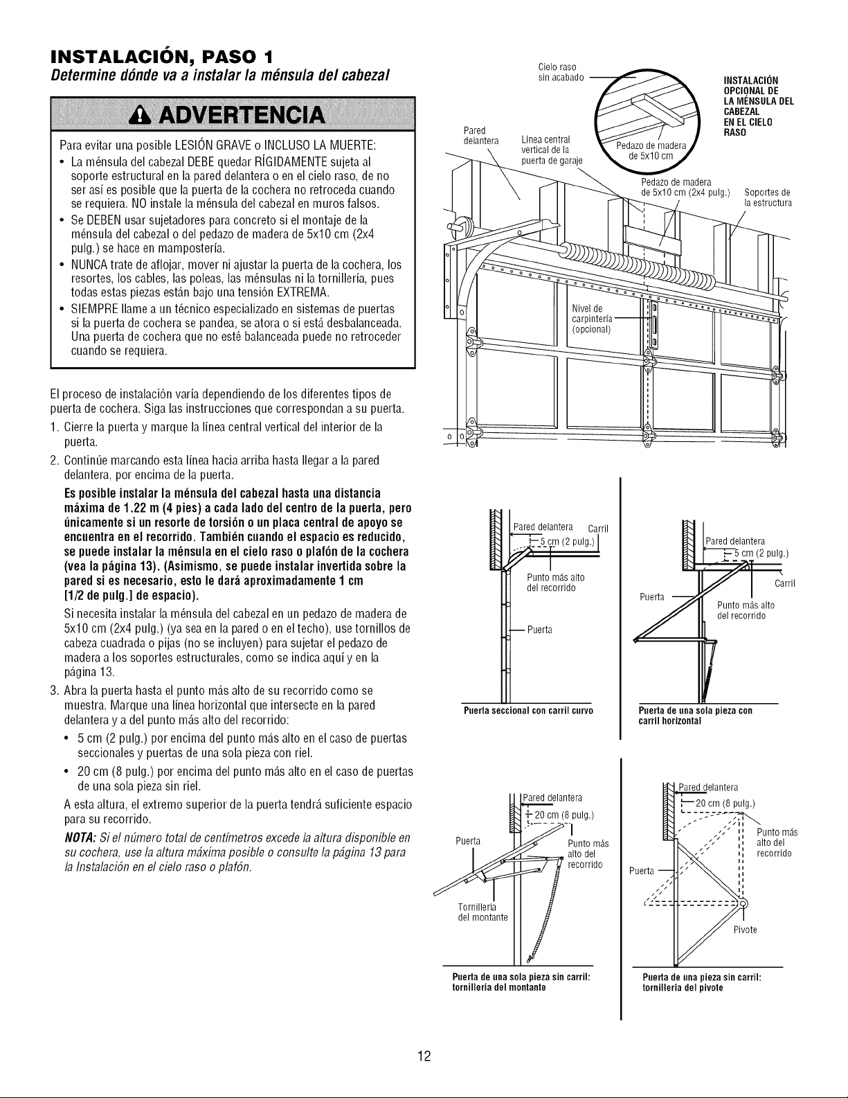
INSTALACION, PASO 1
Determine d6nde vaa insta/ar /a m_nsu/ade/cabeza/
Para evitar una posible LESIONGRAVEo INOLUSOLA MUERTE:
• La m_nsula del cabezalDEBEquedar RJGIDAMENTEsujeta al
soporte estructural en la pared delantera o en el cielo raso, de no
ser asi es posible que la puerta de la cochera no retroceda cuando
se requiera. NO instale la m_nsula del cabezal en muros falsos.
• Se DEBENusar sujetadores para concreto si el montaje de la
m_nsula del cabezalo del pedazode maderade 5x10 cm (2x4
pulg.) se hace en mamposteria.
• NUNCAtrate de aflojar, mover ni ajustar la puerta de la cochera, Ins
resortes, Ins cables, las poleas, las m_nsulas ni latornilleria, pues
todas estas piezasest_.nbajo una tensi6n EXTREMA.
• SIEMPRE Ilameaun t_cnico especializadoen sistemas de puertas
si la puerta de cochera se pandea, seatora o si est,. desbalanceada.
Una puerta de cochera que no est_balanceadapuede no retroceder
cuando se requiera.
Pared
delantera
Cielo raso
sin acabado --
Linen central
vertical de la
puerta de garaje
Pedazode madera
de5x10cm(2x4pulg.)
INSTALACION
OPCIONALDE
LA MENSULA DEL
CABEZAL
EN ELCIELO
RASO
Sopo_es de
la estructura
El proceso de instalaci6n varia dependiendode Ins diferentes tipos de
puerta de cochera. Siga las instrucciones que correspondan a su puerta.
1. Cierre la puerta y marque la linea central vertical del interior de la
puerta.
2. ContinUemarcando esta linea hacia arriba hasta Ilegar a la pared
delantera, por encima de la puerta.
Es posible instalar la m_nsuladel cabezal hasta unadistancia
m_xima de 1.22 m (4 pies) a cada lado del centrode la puerta, pero
_nicamente si un resorte de torsi6n o un placa centralde apoyose
encuentraen el recorrido. Tambi_n cuandoel espacio es reducido,
se puede instalar la m_nsula en el cielo raso o plaf6n de la cochera
(yea la p_gina 13). (Asimismo,se puede instalar invertidasobre la
pared si es necesario, esto le dar_ aproximadamente1 cm
[1/2 de pulg.] de espacio).
Si necesita instalar la m_nsula del cabezalen un pedazo de madera de
5x10 cm (2x4 pulg.) (ya sea en la pared o en el techo), use tornillos de
cabezacuadrada o pijas (no se incluyen) para sujetar el pedazode
maderaa los soportes estructurales, como se indica aqui yen la
p_.gina13.
3. Abra la puerta hasta el punto m_.salto de su recorrido como se
muestra. Marque una linea horizontal que intersecte en la pared
delanteray adel punto m_.salto del recorrido:
• 5 cm (2 pulg.) por encima del punto m_.salto en el caso de puertas
seccionales y puertas de una sola piezacon riel.
• 20 cm (8 pulg.) por encima del punto m_.salto en el caso de puertas
de una sola pieza sin riel.
A esta altura, el extremo superior de la puerta tendr_,suficiente espacio
para su recorrido.
NOTA:Si el nEimerototal de centfmetros excedela altura disponible en
su cochera, use la altura m#xima posible o consulte la p#gina 13 para
la InstalaciSnen el cielo raso o plafSn.
_ Parej delintera Carril
'_,__s_c._12pulg./I
Punto mAs alto
del recorrido
-- Puerta
Puertasectional con carril corvo
P,_._._e Iante ra
- 20 cm (8]pulg.)
Puerta I .I Punto m_s
I_ ar't°odr_o
T_rI ?lillloerrlateII
Paerta de una sola pieza sin carril:
tornilleria del montante
Y
Pared delantera
_5 cm (2 pulg.)
fl "
Carril
Puntom_salto
del recorrido
Pnerta de una sola pieza con
carril horizontal
Pared delantera
,'_20 cm (8 pulg.)
• j _/in _
./ II Punto m_s
/-
i
/" iiII alto del
,, recorrido
Pivote
Paerta de una pieza sin carrih
tornilleria del pivote
12
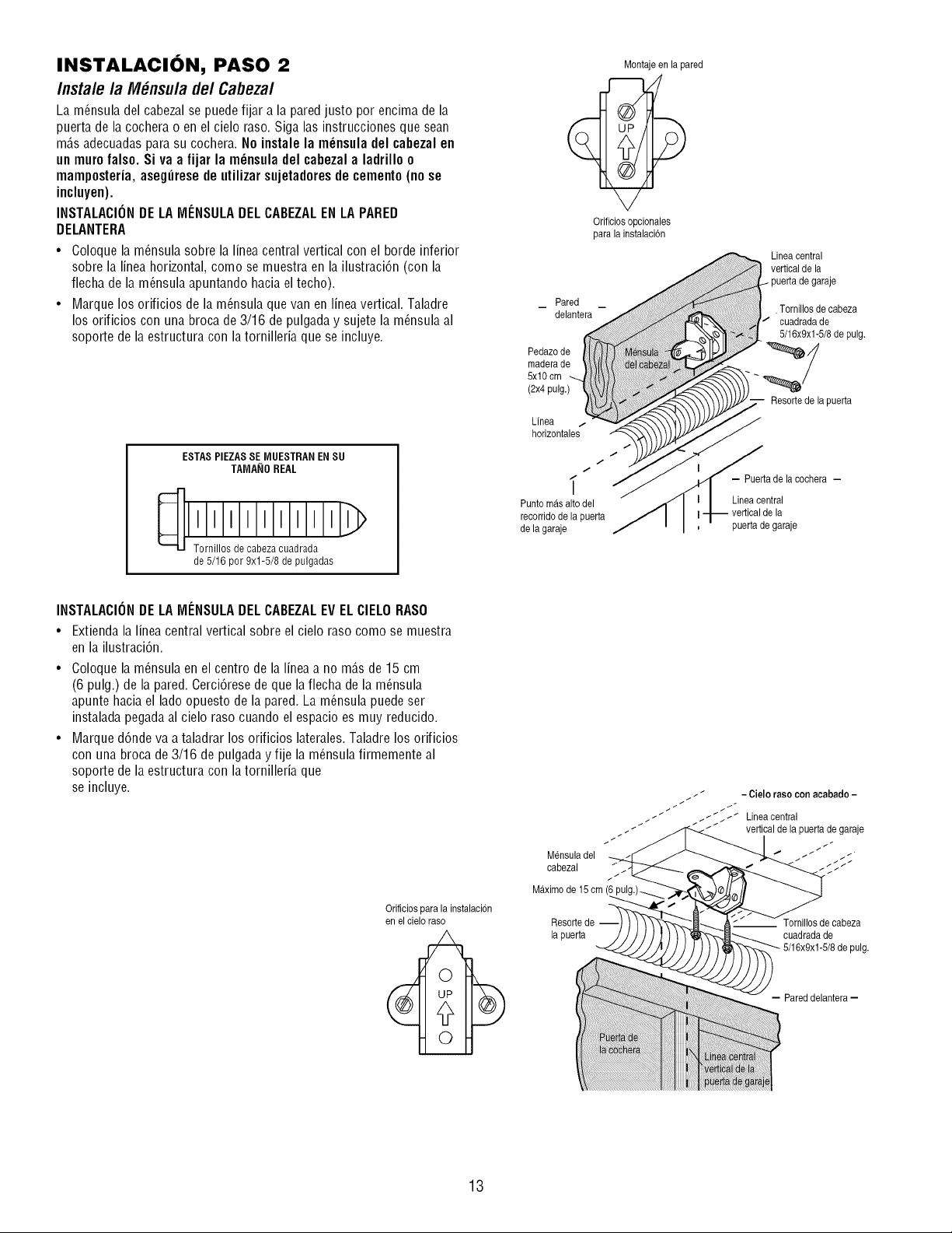
INSTALACION, PASO 2
Instale la M_nsula de/Cabezal
La m_nsula del cabezal se puede fijar a la pared justo por encima de la
puerta de la cochera o en el cielo raso. Siga las instrucciones que sean
m_.sadecuadas parasu cochera. No instale la m_nsula del cabezal en
un muro falso. Si va a fijar la m_nsula del cabezal a ladrillo o
mamposteria, aseghrese de utilizar sujetadoresde cemento (no se
inclupen).
INSTALACIONDE LA MENSULADEL CABEZALEN LA PARED
DELANTERA
• Coloque la m_nsula sobre la linea central vertical con el borde inferior
sobre la linea horizontal, como se muestra en la ilustraci6n (con la
flecha de la m_nsula apuntando haciael techo).
• Marque los orificios de la m_nsula que van en lineavertical. Taladre
los orificios con una broca de 3/16 de pulgada y sujete la m_nsula al
soporte de la estructura con la tornilleria que se incluye.
ESTAS PIEZASSE MUESTRAN EN SU
TAMA_IOREAL
de 5/16 por 9xl-5/8 de pulgadas
Montajeen la pared
Orificiosopcionales
para la instalacbn
Pared
delantera
Pedazode
maderade
5xl 0 cm
(2x4 pulg.)
Linea /
horizontales
Lineacentral
vertical de la
, Tornillosde cabeza
cuadradade
5/16x9x1-5/8de pulg.
Resorte de la puerta
/
/
/
_" - Puerta de la cochera -
Punto mas alto del Linea central
recorrido de la puerta vertical de la
de la garaje puerta de garaje
INSTALACIONDE LA MENSULADEL CABEZALEV ELCIELORASO
• Extienda la linea central vertical sobre el cielo raso como se muestra
en la ilustraci6n.
• Coloque la m_nsula en el centro de la linea a no m_.sde 15 cm
(6 pulg.) de la pared. Cerci6rese de que la flecha de la m_nsula
apunte haciael lado opuesto de la pared. La m_nsula puede ser
instalada pegada al cielo raso cuando el espacio es muy reducido.
• Marque d6nde va a taladrar los orificios laterales.Taladre los orificios
con una broca de 3/16 de pulgada y fije la m_nsula firmemente al
soporte de la estructura con la tornilleria que
se incluye.
Orificios para la instalaci6n
en elcielo raso
_ _ - Cielo rasocon acabado -
_ _//$/_ Lineacentral
t / _ _ _ _ / vertical de la puerta de garaje
Mensuladel _/_
cabezal _ _ _.__
Maximo de 15cm,
Resortede
la puerta
cuadrada de
pulg.
- Pared delantera-
13
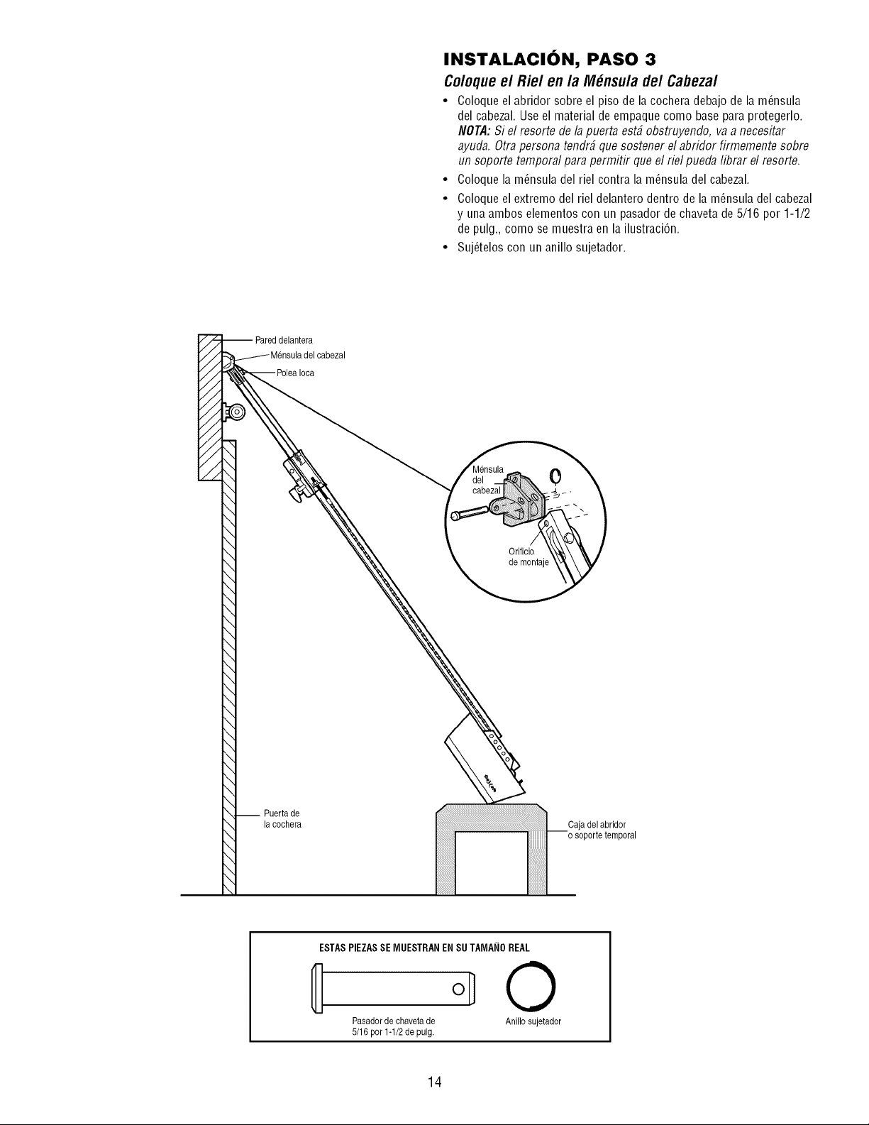
INSTALAClON, PASO 3
Coloque el Riel en la M_nsula de/Cabezal
• Coloque el abridor sobre el piso de la cochera debajo de la m_nsula
del cabezal. Use el material de empaque como base para protegerlo.
NOTA:Si el resorte de la puerta est# obstruyendo, va a necesitar
ayuda. Otra persona tendr# que sostener el abridor firmemente sobre
un soporte temporal para permitir que el rid pueda librar el resorte.
• Coloque la m_nsula del riel contra la m_nsula del cabezal.
• Coloque el extremo del riel delantero dentro de la m_nsula del cabezal
y una ambos elementos con un pasador de chaveta de 5/16 por 1-1/2
de pulg., como se muestra en la ilustracidn.
• Suj_telos con un anillo sujetador.
0
Orificio
de montaje
__ Puertade
la cochera
ESTASPIEZASSE MUESTRAN EN SUTAMANO REAL
0
Pasador de chaveta de Anillo sujetador
5/16por1-1/2depulg.
14
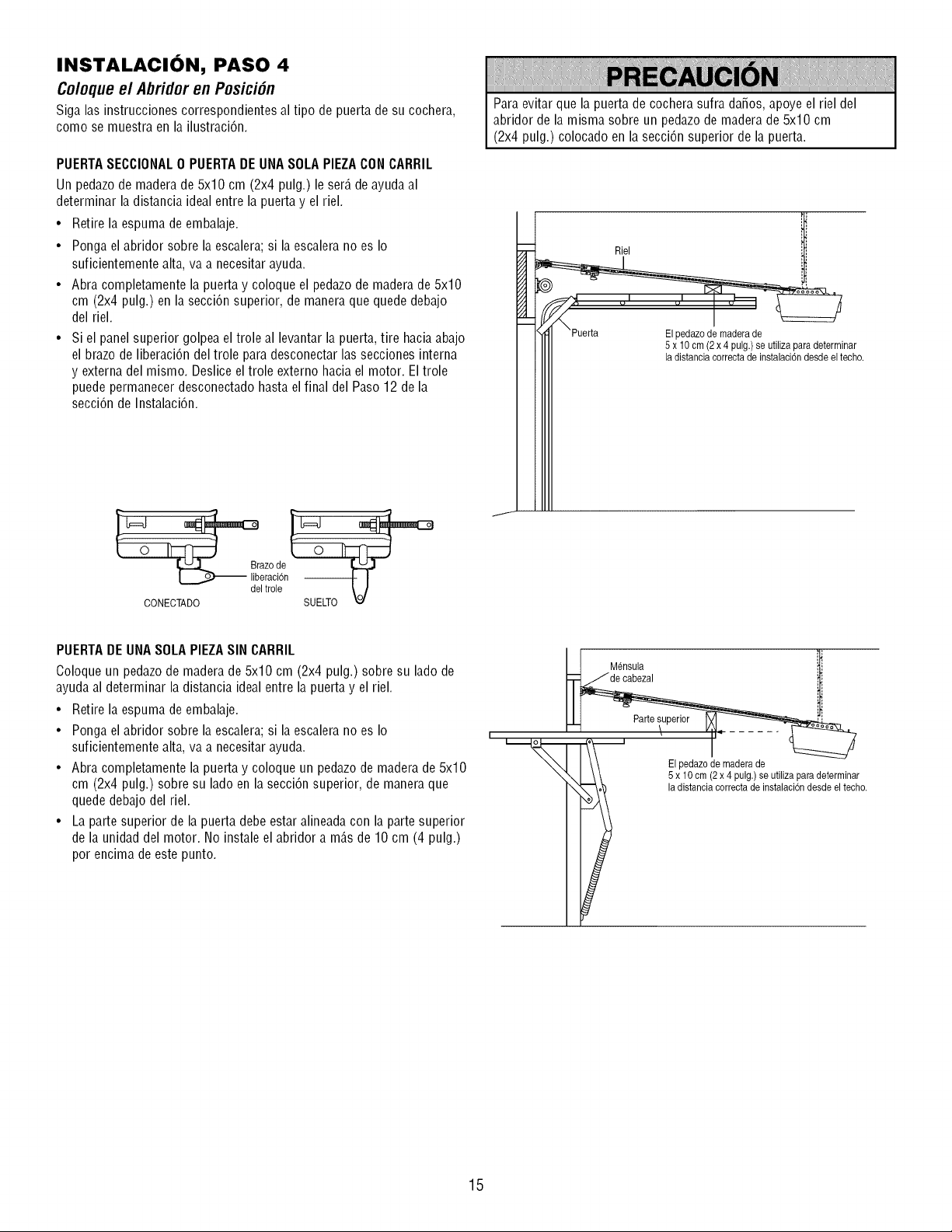
INSTALACION, PASO 4
Coloque el Abridor en Posici6n
Siga las instrucciones correspondientes al tipo de puerta de su cochera,
como se muestra en la ilustraci6n.
PUERTASECCIONAL0 PUERTADE UNASOLAPIEZACON CARRIL
Un pedazode madera de 5x10 cm (2x4 pulg.) le ser_.de ayuda al
determinar la distancia ideal entre la puerta y el riel.
• Retire la espuma de embalaje.
• Ponga el abridor sobre la escalera; si la escalera no es Io
suficientemente alta, va a necesitar ayuda.
• Abra completamente la puerta y coloque el pedazode maderade 5x10
cm (2x4 pulg.) en la secci6n superior, de maneraque quede debajo
del riel.
• Si el panel superior golpea el trole al levantar la puerta, tire hacia abajo
el brazo de liberaci6n del trole para desconectar las secciones interna
y externa del mismo. Deslice el trole externo hacia el motor. El trole
puede permanecer desconectado hasta el final del Paso12 de la
secci6n de Instalaci6n.
Para evitar que la puerta de cochera sufra da_os, apoye el riel del
abridor de la misma sobre un pedazode madera de 5x10 cm
(2x4 pulg.) colocado en la secci6n superior de la puerta.
Riel
El pedazode maderade
5 x 10cm (2x 4 pulg.) seutiliza paradeterminar
la distanciacorrecta de instalaci6ndesde el techo.
deiia°oc,id3n
CONECTADO
PUERTADE UNASOLAPIEZASIN CARRIL
Coloque un pedazode madera de 5x10 cm (2x4 pulg.) sobre su lado de
ayuda al determinar la distancia ideal entre la puerta y el riel.
• Retire la espuma de embalaje.
• Ponga el abridor sobre la escalera; si la escalera no es Io
suficientemente alta, va a necesitar ayuda.
• Abra completamente la puerta y coloque un pedazode madera de 5x10
cm (2x4 pulg.) sobre su lado en la secci6n superior, de manera que
quede debajo del riel.
• La parte superior de la puerta debe estar alineada con la parte superior
de la unidad del motor. No instale el abridor a m_.sde 10 cm (4 pulg.)
por encima de este punto.
I ! Mensula i
El pedazode maderade
5 x 10cm (2x 4 pulg.) seutiliza paradeterminar
la distancia correctade instalaci6ndesde el techo.
15
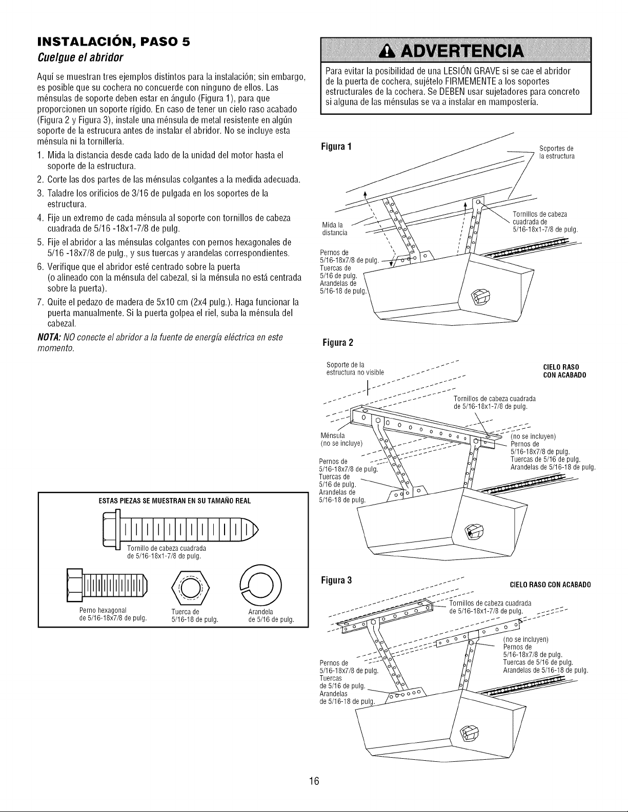
INSTALACION, PASO 5
Cuelgueel abridor
Aqui se muestran tres ejemplos distintos para la instalacidn; sin embargo,
es posible que su cochera no concuerde con ninguno de ellos. Las
m_nsulas de soporte deben estar en_.ngulo(Figura 1), para que
proporcionen un soporte rigido. En caso de tener un cielo raso acabado
(Figura 2 y Figura3), instale una m_nsula de metal resistente en algQn
soporte de la estrucura antes de instalar el abridor. No se incluye esta
m_nsula ni la tornilleria. Figura 1
1. Mida la distancia desde cada lado de la unidad del motor hasta el
soporte de la estructura.
2. Corte las dos partes de las m_nsulas colgantes a la medida adecuada.
3. Taladre los orificios de 3/16 de pulgada en los soportes de la
estructura.
4. Fije un extremo de cadam_nsula al soporte con tornillos de cabeza
cuadrada de 5/16 -18xl-7/8 de pulg. Uidala
distancia
5. Fije el abridor a las m_nsulas colgantes con pernos hexagonalesde
5/16 -18x7/8 de pulg., y sus tuercas y arandelas correspondientes.
6. Verifique que el abridor est_ centrado sobre la puerta
(o alineado con la m_nsula del cabezal,si la m_nsula no est,. centrada
sobre la puerta).
7. Quite el pedazode madera de 5x10 cm (2x4 pulg.). Haga funcionar la
puerta manualmente. Si la puerta golpea el riel, suba la m_nsula del
cabezal.
NOTA:NO conecteel abridor a la fuente de energfael#ctrica en este Figura 2
momento.
ESTAS PIEZASSE MUESTRAN EN SU TAMANOREAL
de 5/16-18xl-7/8 de pulg.
Perno hexagonal Tuerca de
de 5/16-18x7/8 de pulg. 5/16-18 de pulg.
Arandela
de 5/16 de pulg.
Para evitar la posibilidad de una LESIONGRAVEsi se cae el abridor
de la puerta de cochera, suj_telo FIRMEMENTEa los soportes
estructurales de la cochera. Se DEBENusar sujetadores para concreto
si alguna de las m_nsulas se va a instalar en mamposteria.
SopoRes de
la estructura
Pernos de
5/16-18x7/8 de pul
Tuercas de
5/16 de pulg.
Arandelas de
5/16-18 de pul!
\
\
\
Tornillos de cabeza
cuadrada de
5/16-18xl-7/8 de pulg.
Soporte de la _ __ _* _ CIELORASO
estructura no visible _ _ _ _ CON ACABADO
illos de cabeza cuadrada
Mnl_ns____de 5/16-18xl-7/8 de pulg.
_"_'; (no se incluyen)
Pernos de
_ 5/16-18x7/8 de pulg.
Pernos de Tuercas de 5/16 de pulg.
5/16-18x7/8 de Arandelas de 5/16-18 de pulg.
Tuercas de
5/16 de pulg.
Arandelas de
5/16-18 de p
Figura3
Pernos de
5/16-18x7/8 de pulg.
Tuercas
de 5/16 de pulg..
Arandelas
de 5/16-18 de pulg.
fJ CIELO RASOCONACABADO
1_Tornillos de cabezacuadrada
de 5/16-18xl-7/8 de pulg. _;;;;;_
(no se incluyen)
Pernos de
5/16-18x7/8 de pulg.
Tuercas de 5/16 de pulg.
Arandelas de 5/16-18 de pulg.
16
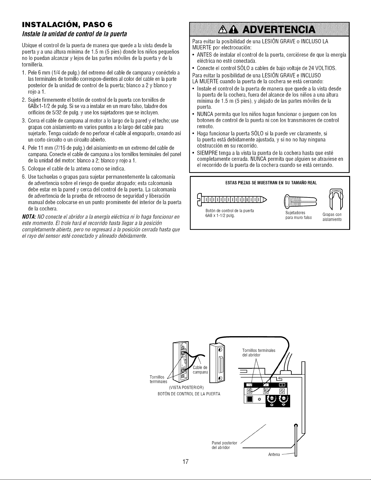
INSTALACION, PASO 6
Instale la unidadde controlde la puerta
Ubique el control de la puerta de manera que quede a lavista desde la
puerta y a una altura minima de 1.5 m (5 pies) donde los ni_os peque_os
no Io puedan alcanzary lejos de las partes m6viles de la puerta y de la
tornilleria.
1. Pele 6 mm (1/4 de pulg.) del extremo del cablede campanay con_cteloa
lasterminales detornillo correspon-dientesal color del cable enla parte
posterior de la unidad de control de la puerta; blanco a 2 y blanco y
rojo a 1.
2. Sujetefirmemente el bot6n de control dela puerta con tornillos de
6ABx1-1/2de pulg. Si seva a instalaren un muro falso, taladre dos
orificios de 5/32 de pulg.y use los sujetadoresque se incluyen.
3. Corra el cable de campanaal motor a Io largo de lapared y eltecho; use
grapas con aislamiento en varios puntos a Io largo del cable para
sujetarlo.Tengacuidado de no perforar el cable al engraparlo,creandoasi
un corto circuito o un circuito abierto.
4. Pele 11 mm (7/16 depulg.) del aislamientoen un extremo del cablede
campana.Conecteel cablede campanaa los tornillos terminales del panel
de launidad del motor: blancoa 2; blanco y rojo a 1.
5. Coloque el cable de la antena como se indica.
6. Usetachuelas o grapas para sujetar permanentemente la calcomania
de advertencia sobre el riesgo de quedar atrapado; esta calcomania
debe estar en la pared y cerca del control de la puerta. La calcomania
de advertencia de la prueba de retroceso de seguridad y liberaci6n
manual debe colocarse en un punto prominente del interior de la puerta
de la cochera.
NOTA:NO conecteel abridor a la energfaelbctrica ni Io haga funcionar en
este momento. El trole har# el recorrido hasta Ilegar a la posiciSn
completamente abierta, pero no regresar#a la posiciSn cerrada hasta que
el rayo del sensor est# conectadoy alineado debidamente.
Para evitar la posibilidad de una LESIONGRAVEo INCLUSOLA
MUERTEpor electrocuci6n:
• ANTES de instalar el control de la puerta, cerci6rese de que la energia
el_ctrica no est_ conectada.
• Conecte el control SOLOa cables de bajo voltaje de 24 VOLTIOS.
Para evitar la posibilidad de una LESIONGRAVEe INCLUSO
LA MUERTEcuando la puerta de la cochera se est,. cerrando:
• Instale el control de la puerta de maneraque quedea la vista desde
la puerta de la cochera, fuera del alcance de los ni_os a una altura
minima de 1.5 m (5 pies), y alejado de las partes m6viles de la
puerta.
• NUNCApermita que los ni_os haganfuncionar o jueguen con los
botones de control de la puerta ni con los transmisores de control
remoto.
• Hagafuncionar la puerta SOLOsi la puede ver claramente, si
la puerta est,. debidamenteajustada, y si no no hayninguna
obstrucci6n en su recorrido.
• SIEMPREtenga a lavista la puerta de la cochera hasta que est_
completamente cerrada. NUNCApermita que alguien se atraviese en
el recorrido de la puerta de la cochera cuando se est,. cerrando.
ESTASPIEZAS SE [V1UESTRANEN SU TA[VIA_IOREAL
lllllllllllllllllllllll'lllllll>
Bot6n de control de la puerta Sujetadores Grapas con
6AB x 1-1/2 pulg. para muro falso aislamiento
Tornillos terminales
del abridor
Tornillos
terminales
(VISTA POSTERIOR)
BOTONDECONTROL DE LA PUERTA
17
Panel posterior
del abridor
Antena
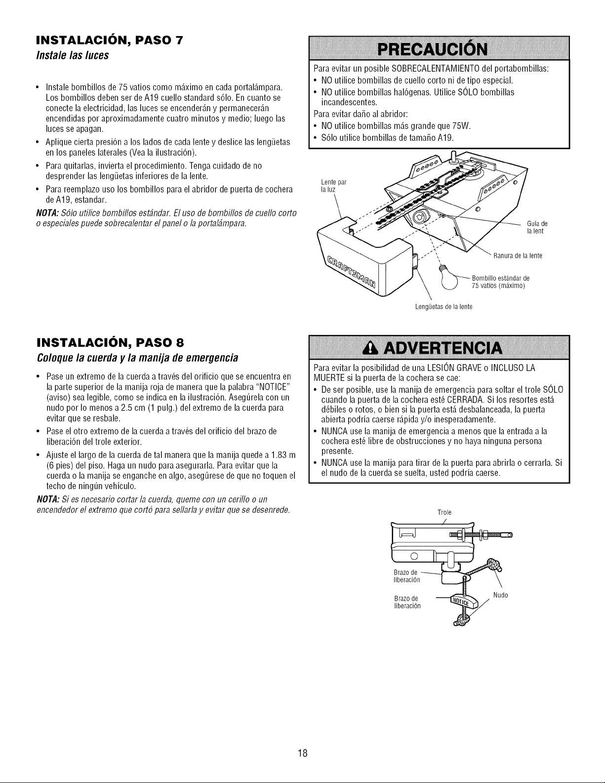
INSTALACION, PASO 7
Instale /as luces
• Instale bombillos de 75 vatios como m_.ximoen cada portal_.mpara.
Los bombillos deben ser de A19 cuello standard s61o.En cuanto se
conecte la electricidad, las luces se encender_.ny permanecer_.n
encendidas por aproximadamente cuatro minutos y medio; luego las
luces se apagan.
• Aplique cierta presidn a los lados de cada lente y deslice las leng_Jetas
en los paneles laterales (Vea la ilustracidn).
• Para quitarlas, invierta el procedimiento. Tenga cuidado de no
desprender las leng_Jetasinferiores de la lente.
• Para reemplazouso los bombillos para el abridor de puerta de cochera
de A19, estandar.
NOTA:$51o ufilice bombiflos est#ndar. El uso de bombiflos de cuello corto
o especialespuede sobrecalentar el panel o la portal#mpara.
Para evitar un posible SOBRECALENTAMIENTOdel portabombillas:
• NO utilice bombillas de cuello corto ni de tipo especial.
• NO utilice bombillas hal6genas. Utilice SOLObombillas
incandescentes.
Para evitar dafio al abridor:
• NO utilice bombillas m_.sgrande que 75W.
• %1o utilice bombillas de tamafio A19.
Lentepar
laluz
Guia de
la lent
Ranura de la lente
_ ombillo est_ndar de
75 vatios (m_ximo)
Leng_]etasde la lente
INSTALACION, PASO 8
Coloquela cuerday la manija de emergencia
• Paseun extremo de lacuerda a trav_s del orificio que se encuentra en
la parte superior de la manija roja de manera que la palabra "NOTICE"
(aviso) sea legible, como se indica en la ilustraci6n. Aseg_rela con un
nudo por Io menos a 2.5 cm (1 pulg.) del extremo de la cuerda para
evitar que se resbale.
• Paseel otro extremo de la cuerda a trav_s del orificio del brazo de
liberaci6n del trole exterior.
• Ajuste el largo de la cuerda de tal manera que la manija quede a 1.83 m
(6 pies) del piso. Hagaun nudo para asegurarla. Paraevitar que la
cuerda o la manija se enganche en algo, asegQresede que no toquen el
techo de ning_n vehiculo.
NOTA:Si es necesario cortar la cuerda, queme con un ceriflo o un
encendedor el extremo que cort5 para sellarlay evitar que se desenrede.
Para evitar la posibilidad de una LESIONGRAVEo INCLUSOLA
MUERTEsi la puerta de la cochera se cae:
• De ser posible, use la manija de emergencia para soltar eltrole SOLO
cuando la puerta de la cochera est_ CERRADA.Si los resortes est,.
d_biles o rotos, o bien si la puerta est,. desbalanceada,la puerta
abierta podria caerse r_.piday/o inesperadamente.
• NUNCAuse la manija de emergencia a menos que la entrada a la
cochera est_ libre de obstrucciones y no haya ninguna persona
presente.
• NUNCAuse la manija para tirar de la puerta para abrirla o cerrarla. Si
el nudo de lacuerda se suelta, usted podria caerse.
Trole
!__n ___1__
Brazo de __[_ _, Nudo
liberaciOn
18
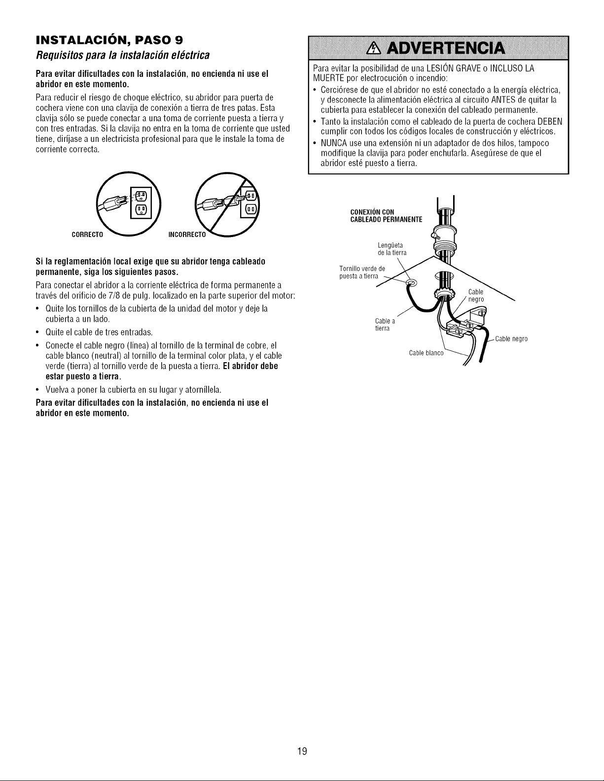
INSTALACION, PASO 9
Requisitosparala instalaci6nel ctrica
Para evitar dificultadescon la instalaci6n, no enciendani use el
abridor en este momento.
Para reducir el riesgo de choque el6ctrico, su abridor para puerta de
cochera viene con una clavija de conexi6n a tierra de tres patas. Esta
clavija s61ose puedeconectar a unatoma de corriente puesta a tierra y
con tres entradas. Si la clavija no entra en la toma de corriente que usted
tiene, dirijase a un electricista profesional paraque le instale la toma de
corriente correcta.
CORREC_
INCORRECTC
Si la reglamentaci6n local exige que su abridortenga cableado
permanente, siga los siguientespasos.
Para conectar el abridor a la corriente el_ctrica deforma permanente a
trav_s del orificio de 7/8 de pulg. Iocalizado en la parte superior del motor:
• Quite los tornillos de la cubierta de la unidad del motor y deje la
cubierta a un lado.
• Quite el cable de tres entradas.
• Conecte el cable negro (linea) al tornillo de laterminal de cobre, el
cable blanco (neutral) al tornillo de laterminal color plata, y el cable
verde (tierra) al tornillo verde de la puesta a tierra. El abridor debe
estar puesto a tierra.
• Vuelva a poner la cubierta en su lugar y atornillela.
Para evitar dificultadescon la instalaci6n, no enciendani use el
abridor en este momento.
Para evitar la posibilidad de una LESIONGRAVEo INCLUSOLA
MUERTEpor electrocuci6n o incendio:
• Cerci6rese de que el abridor no est_ conectado a la energia el_ctrica,
y desconecte la alimentaci6n el_ctrica al circuito ANTESde quitar la
cubierta para establecer la conexi6n del cableado permanente.
• Tanto la instalaci6n como el cableado de la puerta de cochera DEBEN
cumplir con todos los c6digos locales de construcci6n y el6ctricos.
• NUNCAuse una extensi6n ni un adaptador dedos hilos, tampoco
modifique la clavija para poder enchufarla. Aseg_resede que el
abridor est_ puesto a tierra.
CONEXIONCON
CABLEADOPERMANENTE
Leng_ieta
de la tierra
Tornillo verde de
puesta atierra
Cable a
tierra
Cable blanco
negro
19
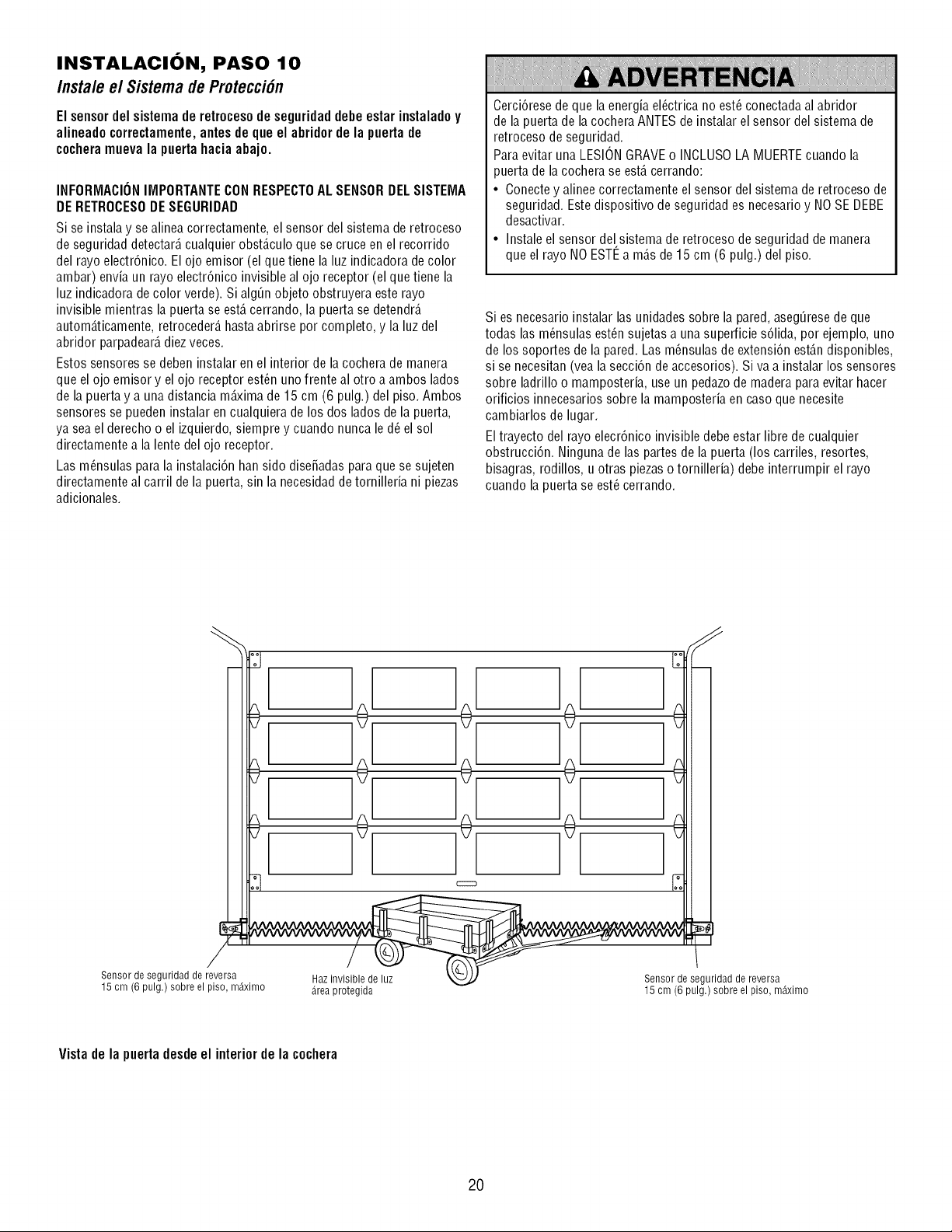
INSTALACION, PASO 10
Instale e/Sistema de Protecci6n
Elsensordelsistemaderetrocesodeseguridaddebeestarinstaladoy
alineadocorrectamente,antesdequeel abridordela puertade
cocheramuevala puertahaciaabajo.
INFORMACIONIMPORTANTECONRESPECTOAL SENSORDELSISTEMA
DERETROCESODESEGURIDAD
Si se instalay se alinea correctamente, el sensor del sistema de retroceso
de seguridad detectar_,cualquier obst_.culoque se cruce en el recorrido
del rayo electr6nico. El ojo emisor (el que tiene la luz indicadora de color
ambar) envia un rayo electr6nico invisible al ojo receptor (el que tiene la
luz indicadora de color verde). Si alg_n objeto obstruyera este rayo
invisible mientras la puerta se est,. cerrando, la puerta se detendr_.
autom_.ticamente,retroceder_,hasta abrirse por completo, y la luz del
abridor parpadear_,diez veces.
Estos sensores se deben instalar en el interior de la cochera de manera
que el ojo emisor y el ojo receptor est_n uno frente al otro a ambos lados
de la puerta y a una distancia m_ima de 15 cm (6 pulg.) del piso. Ambos
sensores se pueden instalar en cualquiera de los dos lados de la puerta,
ya sea el derecho o el izquierdo, siempre y cuando nunca le d_ el sol
directamente a la lente del ojo receptor.
Las m_nsulas para la instalaci6n han sido dise_adas paraque se sujeten
directamente al carril de la puerta, sin la necesidadde tornilleria ni piezas
adicionales.
Cerci6rese de que la energia el_ctrica no est_ conectada al abridor
de la puerta de la cocheraANTES de instalar el sensor del sistema de
retroceso de seguridad.
Para evitar una LESIONGRAVEo INCLUSOLA MUERTEcuando la
puerta de la cochera se est,. cerrando:
• Conectey alinee correctamente el sensor del sistema de retroceso de
seguridad. Este dispositivo de seguridad es necesario y NOSE DEBE
desactivar.
• Instale el sensor del sistema de retroceso de seguridad de manera
que el rayo NO ESTI_a m_.sde 15 cm (6 pulg.) del piso.
Si es necesario instalar las unidades sobre la pared, aseg_rese de que
todas las m_nsulas est_n sujetas a una superficie s61ida,por ejemplo, uno
de los soportes de la pared. Las m_nsulas de extensi6n est_.ndisponibles,
si se necesitan(vea la secci6n de accesorios). Siva a instalar los sensores
sobre ladrillo o mamposteria, use un pedazode madera para evitar hacer
orificios innecesarios sobre la mamposteria en caso que necesite
cambiarlos de lugar.
Eltrayecto del rayo elecr6nico invisible debe estar libre de cualquier
obstrucci6n. Ninguna de las partes de la puerta (los carriles, resortes,
bisagras, rodillos, u otras piezaso tornilleria) debe interrumpir el rayo
cuando la puerta se est_cerrando.
Sensor de seguridad de reversa
15 cm (6 pulg.) sobre el piso, m_ximo
Haz invisible de luz
area protegida
Sensor de seguridad de reversa
15 cm (6 pulg.) sobre el piso, m_ximo
Vistadela puertadesdeel interior dela cochera
2O
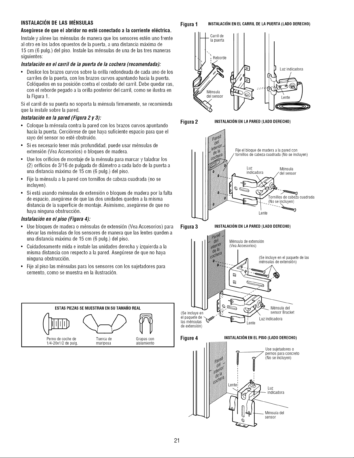
INSTALACIONDE LAS MENSULAS
Aseg_resede que el abridor no est_ conectadoa la corrienteel_ctrica.
Instale y alinee las m_nsulas de manera que los sensores est_n uno frente
al otro en los lados opuestos de la puerta, a una distancia m_.ximade
15 cm (6 pulg.) del piso. Instale las m_nsulas de una de lastres maneras
siguientes:
Instalaci6n en el carril de la puerta de la cocflera(recomendada):
• Deslice los brazos curvos sobre la orilla redondeadade cada uno de los
carriles de la puerta, con los brazos curvos apuntando hacia la puerta.
Col6quelos ensu posici6n contra el costado del carril. Debe quedar ras,
con el reborde pegado a la orilla posterior del carril, como se ilustra en
la Figura 1.
Si el carril de su puerta no soporta la m_nsulafirmemente, se recomienda
que la instale sobre la pared.
Instalacifin en la pared (Figura 2 y 3):
• Coloque la m_nsula contra la pared con los brazos curvos apuntando
hacia la puerta. Cercidrese de que hayasuficiente espacio para que el
rayo del sensor no est_ obstruido.
• Si es necesariotener m_.sprofundidad, puede usar m_nsulas de
extensidn (VeaAccesorios) o bloques de madera.
• Use los orificios de montaje de la m_nsula para marcar y taladrar los
(2) orificios de 3/16 de pulgada de di_.metroa cada lado de la puerta a
una distancia m_.ximade 15 cm (6 pulg.) del piso.
• Fije la m_nsula a la pared con tornillos de cabezacuadrada (no se
incluyen).
• Si est,. usando m_nsulas de extensidn o bloques de madera por la falta
de espacio, asegQresede que las dos unidades queden a la misma
distancia de la superficie de montaje. Asimismo, asegQresede que no
haya ninguna obstrucci6n.
Instalacifin en el piso (Figura 4):
• Use bloques de madera o m_nsulas de extensi6n (YeaAccesorios) para
elevar las m_nsulas de los sensores de manera que las lentes queden a
una distancia m_.ximade 15 cm (6 pulg.) del piso.
• Cuidadosamente mida e instale las unidades derecha y izquierda a la
misma distancia con respecto a la pared.AsegQresede que no haya
ninguna obstrucci6n.
• Fije al piso las m_nsulas para los sensores con los sujetadores para
cemento, como se muestra en la ilustraci6n.
ESTASPIEZASSE MUESTRANEN SU TAMA_IOREAL
Perno de coche de Tuerca de Grapas con
1/4-20xl/2 de pulg. mariposa aislamiento
Figura1 INSTALACIONEN EL CARRILDE LA PUERTA(LADO DERECHO)
I I_l_Oarri,de
/Hiapuerta
_,l I Reborde
sensor
Figura2 INSTALACIONEN LA PARED(LADO DERECHO)
Figura3
Fije el bloque de madera a la pared con
i tornillOSLiI oabeza oeadradaiilsSuiainCluyen )
del sensor
:L_ --.-'_
Lente
INSTALACIONENLA PARED(LADO DERECHO)
Mdnsula de extension
(Vea Accesorios)
(Se incluye en el paquete de las
mdnsulas de extension)
(Se incluye en
el paquete de
las m6nsulas
de extension)
Figure4
Mdnsuladel
sensorBracket
Luzindicadora
Lente
INSTALACIONENEL PISO(LADO DERECHO)
Usesujetadoreso
_ ernosparaconcreto
(Nose incluyen)
,,
Luz
indicadora
sensor
21
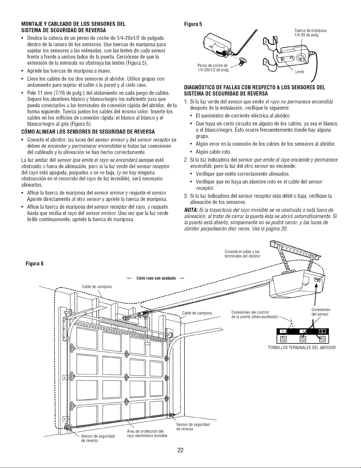
MONTAJEY CABLEADODE LOS SENSORESDEL
SISTEMA DE SEGURIDADDE REVERSA
• Deslice la cabezade un perno de coche de 1/4-20xl/2 de pulgada
dentro de la ranura de los sensores. Usetuercas de mariposa para
sujetar los sensores alas m_nsulas, con las lentes de cadasensor
frente a frente a ambos ladosde la puerta. Cerci6resede que la
extensi6n de la m_nsula no obstruya las lentes (Figura 5).
• Apriete las tuercas de mariposa a mano.
• Lleve los cables de los dos sensores al abridor. Utilice grapas con
aislamiento para sujetar el cable a la pared y al cielo raso.
• Pele 11 mm (7/16 de pulg.) del aislamiento en cadajuego de cables.
Separe los alambres blanco y blanco/negro los suficiente para que
pueda conectarlos alas terminales de conexi6n r_.pidadel abridor, de la
forma siguiente. Tuerzajuntos los cables del mismo color. Inserte los
cables en los orificios de conexi6n r_.pida:el blanco al blanco y el
blanco/negro al gris (Figura 6).
COMOALINEARLOSSENSORESDESEGURIDADDE REVERSA
• Conecte el abridor; las luces del sensor emisory del sensor receptor se
deben de encenderypermanecerencendidas si todas las conexiones
del cableadoy la alineaci6n se han hecho correctamente.
La luz ambar del sensor que emite el rayo se encender#aunque est_
obstruido o fuera de alineaci6n, pero si la luz verde del sensor receptor
del rayo est,. apagada,parpadea o se ve baja,(y no hay ninguna
obstrucci6n en el recorrido del rayo de luz invisible), ser_.necesario
alinearlos.
• Afloje la tuerca de mariposa del sensor emisory reajuste el sensor.
Apunte directamente al otro sensory apriete la tuerca de mariposa.
• Afloje la tuerca de mariposa del sensor receptor del rayo, y reajuste
hasta que reciba el rayo del sensor emisor. Una vez que la luzverde
brille continuamente, apriete la tuerca de mariposa.
Figura5
Tuerca de mariposa
1/4-20 de pulg.
Pernodecoohede _
1/4-20xl/2depulg.
DIAGNOSTICODE FALLASCON RESPECTOA LOSSENSORESDEL
SISTEIVIADE SEGURIDADDEREVERSA
1. Si la luz verdedel sensor que emite el rayo no permanece encendida
despu_s de la instalaci6n, verifique Io siguiente:
• El suministro de corriente el_ctrica al abridor.
• Quehaya un corto circuito en alguno de los cables, ya sea el blanco,
o el blanco/negro. Esto ocurre frecuentemente donde hay alguna
grapa.
• AIgQn error en la conexi6n de los cables de los sensores al abridor.
• AIgQn cable roto.
2. Si la luz indicadora del sensor queemite el rayo enciendey permanece
encendida, pero la luz del otro sensor no enciende:
• Verifique que est_n correctamente alineados.
• Verifique que no haya un alambre roto en el cable del sensor
receptor.
3. Si la luz indicadora del sensor receptor esta d_bil o baja,verifique la
alineaci6n de los sensores.
NOTA:Si la trayectoria del rayo invisible se ve obstruida o est# fuera de
alineaci6n, al tratar de cerrar lapuerta #sta se abrir# autom#ticamente. Si
la puerta est# abierta, simplemente no sepodr# cerrar, y las luces de
abridor parpadear#ndiez veces. Veala p#gina 20.
Figura6
Cable de can _ana
-- Cielo raso con acabado
Sensordeseguridad
dereversa
Areade protecci6ndel
rayoelectr6nicoinvisible
Conecte el cable a las
terminales del abridor
Cable de campana
Conexiones
Conexionesdelcontrol delsensor
delapuerta (linea punteada) _ _/,
TORNILLOS TERMINALES DEL ABRIDOR
Sensordeseguridad
de reversa
22
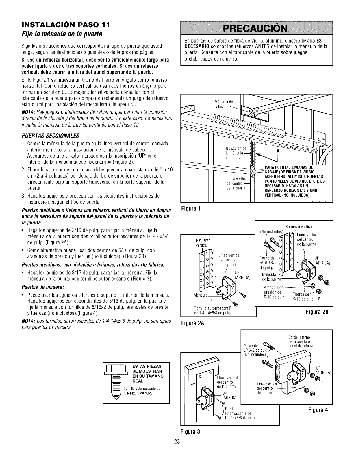
INSTALACION PASO 11
Fije la mGnsula de la puerta
Siga las instrucciones que correspondan al tipo de puerta que usted
tenga, seg_n las ilustraciones siguientes o de la pr6xima p_.gina.
Si usa un refuerzo horizontal, dehe set Io suficientemente largo para
poder fijarlo a doso ires soportesverticales. Si usa un refuerzo
vertical, dehe cuhrir la altura del panel superior de la puerta.
En la Figura 1 se muestra un tramo de hierro en _.ngulocomo refuerzo
horizontal. Como refuerzo vertical, se usan dos hierros en _.ngulopara
formar un perfil en U. La mejor alternativa seria consultar con el
fabricante de la puerta para comprar directamente un juego de refuerzo
estructural para instalaci6n del mecanismo de apertura.
NOTA:Hayjuegos prefabricados de refuerzo que permiten la conexiSn
directa de la chaveta y del brazo de la puerta. En este caso, no necesitar#
instalar la m#nsula de la puerta; continfie con el Paso 12.
PUERTAS SECCIONALES
1. Centre la m_nsula de la puerta en la linea vertical de centro marcada
anteriormente para la instalaci6n de la m_nsula de cabecera.
Aseg_resede que el lado marcado con la inscripci6n "UP"en el
interior de la m_nsula quede hacia arriba (Figura 2).
2. El borde superior de la m_nsula debe quedar a una distancia de 5 a 10
cm (2 a 4 pulgadas) por debajo del borde superior de la puerta, o
directamente bajo un soporte transversal en la parte superior de la
puerta.
3. Haga los agujeros y proceda con las siguientes instrucciones de
instalaci6n, seg_n el tipo de puerta:
Puertas met_licas e /ivianas conrefuerze vertical de hierre en _ngule
entre/a nervadura de soportede/panel de/a puerta y/a m_nsu/a de
/a puerta:
• Haga los agujeros de 3/16 de pulg. para fijar la m_nsula. Fije la
m_nsula de la puerta con dos tornillos autorroscantes de 1/4-14x5/8
de pulg. (Figura 2A)
• Como alternativa puede usar dos pernos de 5/16 de pulg. con
arandelas de presi6n y tuercas (no incluidos). (Figura 2B)
Puertas met_licas, con aislaci6n o/ivianas, reforzadasde f_brica:
• Haga los agujeros de 3/16 de pulg. para fijar la m_nsula. Fije la
m_nsula de la puerta con tornillos autorroscantes (Figura3).
Puertas de madera:
• Puede usar los agujeros lateraleso superior e inferior de la m_nsula.
Haga los agujeros correspondientes de 5/16 de pulg. en la puerta y
fije la m_nsula con tornillos de 5/16x2 de pulg., arandelas de presi6n
y tuercas (no incluidos).(Figura 4)
NOTA:Los tomillos autorroscantes de 1/4-14x5/8 de pulg. no son aptos
para puertas de madera.
ESTAS PIEZAS
SE MUESTRAN
EN SU TAMAI_IO
REAL
Tornillo autorroscantede
1/4-14x5/8de pulg.
En puertas de garaje de fibra de vidrio, aluminio o acero liviano ES
NEOESARIOcolocar los refuerzos ANTESde instalar la m_nsula de la
puerta. Consulte con el fabricante de la puerta sobre juegos
prefabricados de refuerzo.
+su,delII
o o o o
o o o o o o o
o o o
I I _0 FINO. ALUIVIINIO.PUERTAS
Llnea ver[ical ' '
I I __ 1 NECESARIOINSTALAR UN
+1 oe,apuer,aII.;i . FUEnZOHO.,ZO.+A,YU.O
H
Figura 1
Refuerzo
vertical
Linea vertical
del centro
de la puerta
i/ UP
i_ ARRIBA)
M6nsula _\_1_
de la puerta ",
Tornillo autorroscant_
de 1/4-14x5/8 de pulg.
Figura 2A
nea vertical
- del centro
de la puerta
UP
(ARRIBA)
Refuerzo vertical
(No/incluid_ Linea vertical
L@'_ Io-'llJ,J delcentro
Tollililde _ paerta
Pernode I0ll P^,,I ', UP
5/16-18x2Iotb.l:l'-.
epu+IoiCSLS.,,-A &qr
M_nsula _ _ _j_-
de la puerta _..
Arandela de---------_-_
i
presi6n de Tuerca de 'J_-
5/16 de pulg. 5/16 de pulg.-18
Figura2B
Borde interno
de la puerta o
Perno de _ panel de refuezo
5/16x2 de pulg./_\
(No incluido_ _
_ ecae_[; i
de la puerta _ ,,.v,._.
autorroscante de
1/4-14x5/8 de pulg.
Figura 4
Figura 3
23
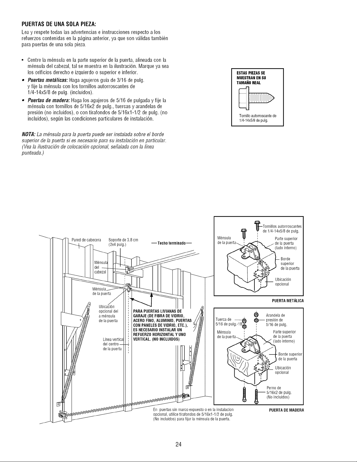
PUERTAS DE UNA SOLA PIEZA:
Lea y respetetodas las advertencias e instrucciones respecto a los
refuerzos contenidas en la p_.ginaanterior, ya que son v_Jidastambi_n
para puertas de una sola pieza.
• Centre la m_nsula en la parte superior de la puerta, alineadacon la
m_nsula del cabezal, tal se muestra en la ilustraci6n. Marque ya sea
los orificios derecho e izquierdo o superior e inferior.
• Puertas met#licas: Haga agujeros guia de 3/16 de pulg.
y fije la m_nsula con los tornillos autorroscantes de
1/4-14x5/8 de pulg. (incluidos).
• Puertas de madera: Haga los agujeros de 5/16 de pulgada y fije la
m_nsula con tornillos de 5/16x2 de pulg., tuercas y arandelasde
presi6n (no incluidos), o con tirafondos de 5/16x1-1/2 de pulg. (no
incluidos), seg_n las condiciones particulares de instalaci6n.
NOTA:La m#nsula para la puerta puede ser instalada sobre el borde
superior de la puerta si es necesario para su instalaciSn en particular.
(Yea la ilustraciSn de colocaciSn opcional, sefialadacon la 1fiTea
punteada.)
ESTASPIEZASSE
MUESTRANEN SU
TAMANOREAL
Tornilloautorroscantede
1/4-14x5/8de pulg.
Pared de cabecera Soporte de 3.8 cm
(2x4 pulg.)
M6nsul_
de la puerta
opcional del
a m6nsula
de la puerta
Linea vertica
del
de la puerta
--Techo terminado--
PARA PUERTASLIVIANAS DE
GARAJE(DE FIBRADEVIDRIO,
ACEROFINO, ALU[VllNIO,PUERTAS
CONPANELESDE VIDRIO, ETC.),
ES NECESARIOINSTALAR UN
REFUERZOHORIZONTALY UNO
VERTICAL.(NO INCLUIDOS)
M6nsula
En puertas sin marco expuesto o en la instalacion
opcional, utilice tirafondos de 5/16x1-1/2 de pulg.
(No incluidos) para fijar la mdnsula de la puerta.
'l_--Tornillos autorroscantes
1_ _de 1/4-14x5/8 de pulg.
, Parte superior
la puerta
(lado interno)
superior
de la puerta
UbicaciOn
opcional
PUERTAMETALICA
Tuerca de
5/16 de pulgMS_
M6nsula
de
e Arandela de
presi0n de
, 5/16 de pulg.
, Parte superior
de la puerta
(lado interno)
• Borde superior
de la puerta
UbicaciOn
opcional
L Perno de
5/16x2 de pulg.
(No incluidos)
PUERTADE MADERA
24
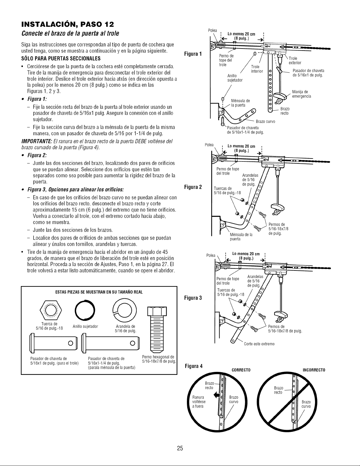
INSTALACION, PASO 12
Conecteel brazodela puertaal trole
Siga las instrucciones que correspondan al tipo de puerta de cochera que
usted tenga, como se muestra a continuacien yen la pD.ginasiguiente. Figura 1
SOLOPARA PUERTASSECCIONALES
• Cercierese de que la puerta de la cochera est_ completamente cerrada.
Tire de la manija de emergencia paradesconectar el trole exterior del
trole interior. Desliceel trole exterior hacia atrD.s(en direccien opuesta a
la polea) por Io menos 20 cm (8 pulg.) como se indica en las
Figuras 1,2 y 3.
• Figura 1:
- Fije la seccien recta del brazode la puertaal trole exterior usando un
pasador dechaveta de 5/16xl pulg.Asegure la conexiencon el anillo
sujetador.
- Fije laseccien curva del brazo a la m_nsula de la puerta de la misma
manera, con un pasador de chaveta de 5/16 por 1-1/4 de pulg.
IMPORTANTE:El ranura en el brazo recto de la puerta DEBE voltbesedel
brazo curvado de la puerta (Figura 4).
• Figura 2:
- Junte las dos secciones del brazo, Iocalizandodos pares de orificios
que se puedanalinear. Seleccione dos orificios que est_n tan
separados como sea posible para aumentar la rigidez del brazo de la
puerta.
• Figura 3, Opcionespara alinear los orificios: Figura2
- En caso de que los orificios del brazo curvo no se puedan alinear con
los orificios del brazo recto, desconecte el brazo recto y corte
aproximadamente 15 cm (6 pulg.) del extremo que no tiene orificios.
Vuelva a conectarlo al trole, con el extremo cortado haciaabajo,
como se muestra.
- Junte las dos secciones de los brazos.
- Localice dos paresde orificios de ambas secciones que se puedan
alinear y Onaloscon tornillos, arandelasy tuercas.
• Tire de la manija de emergencia haciael abridor en un D.ngulode 45
grados, de maneraque el brazo de liberacien del trole est_ en posicien
horizontal. Procedaa la seccien de Ajustes, Paso 1, en la pD.gina27. El
trole volverD,a estar listo automD.ticamente,cuando se opere el abridor.
ESTASPIEZAS SE MUESTRAN ENSU TAMA_IOREAL
Tuerca de
5/16 de pulg.-18 Anillo sujetador Arandela de
5/16 de pulg.
ol
Pasador de chaveta de Pasador de chaveta de
5/16xl de pulg. (para el trole) 5/16x1-1/4 de pulg.
(parala mensula de la puerta)
Perno hexagonal de
5/16-18x7/8 de pulg.
Figura3
Figura 4
Polea
: Lo menos20 cm :
A'- _8,.ig.) __:
tope del T,!o/e^,
/ ro,e/ 11"5........
/ interior Iol '_ _ Pasadordechaveta
Anillo I°1 I de 5/16xl de pulg.
_jetador I_11
/ I°lJ Manija de
,7 I?1_ _ emergencia
'y Mensula de iol ,/__r-'-
_ IoJ_ Brazo
_X_J v recto
" _[ _ _'Pasadorde chave_arazOcurvo
de5/16x1-1/4depulg.
Polea
Lo menos20 cm ,,
(8pulg.) ...),,
Mensula de la
puerta
Pernos de
5/16-18x7/8
de pulg.
Polea\ :_ Lon_npOu_2_ cm_i
_ \ _- f_ " "7,
,, - _
Arandelas
Perno de tope de 5/%
del trole de pulg.Z /
Tuercas de / _'/
5/16 de pulg.-ll! o_
__ 5P_lr_-°_lSedx_de pulg.
v Corte este extremo
CORRECTO INCORRECTO
25
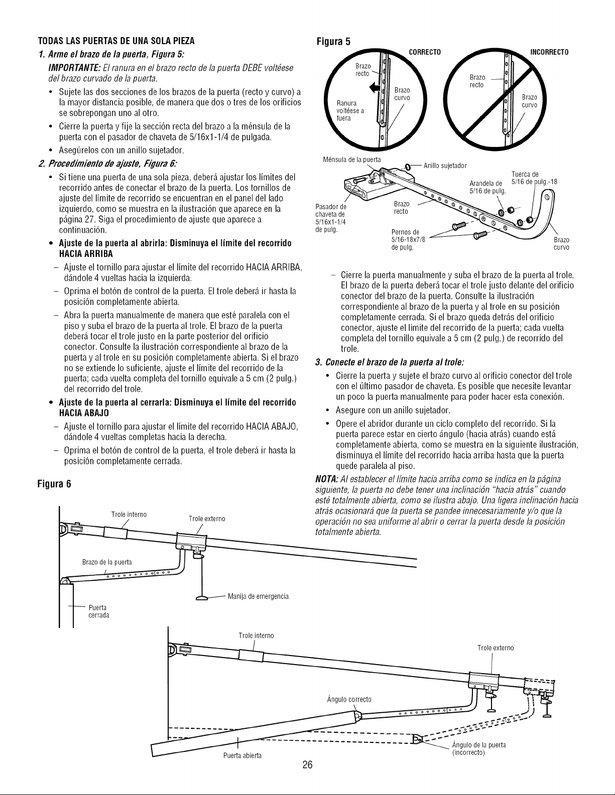
TODAS LASPUERTASDEUNASOLAPIEZA
1. Arme el brazode/a puerta, Figura 5:
IMPORTANTE:El ranura el7el brazo recto de la puerta DEBEvolt#ese
del brazo curvado de la puerta.
• Sujete las dos secciones de los brazos de la puerta (recto y curvo) a
la mayor distancia posible, de manera que dos o tres de los orificios
se sobrepongan uno al otro.
• Cierre la puerta y fije la secci6n recta del brazo a la m_nsula de la
puerta con el pasador de chaveta de5/16x1-1/4 de pulgada.
• Aseg_relos con un anillo sujetador.
2.Procedimientode ajuste,Fi_ura6:
• Sitiene una puerta de una sola pieza,deber_,ajustar los limites del
recorrido antes de conectar el brazo de la puerta. Los tornillos de
ajuste del limite de recorrido se encuentran en el panel del lado
izquierdo, como se muestra en la ilustraci6n que aparece en la
p_.gina27. Siga el procedimiento de ajuste que aparece a
continuaci6n.
• Ajuste de la puerta al abrirla: Disminuyael limite del recerrido
HACIAARRIBA
- Ajuste el tornillo paraajustar el limite del recorrido HACIAARRIBA,
d_.ndole4 vueltas hacia la izquierda.
- Oprima el bot6n de control de la puerta. Eltrole deber_,ir hasta la
posici6n completamente abierta.
- Abra la puerta manualmente de maneraque est_ paralela con el
piso y suba el brazo de la puerta al trole. El brazode la puerta
deber_,tocar el trole justo en la parte posterior del orificio
conector. Consulte la ilustraci6n correspondiente al brazo de la
puerta y al trole en su posici6n completamente abierta. Si el brazo
no se extiende Io suficiente, ajuste el limite del recorrido de la
puerta; cada vuelta completa del tornillo equivale a 5 cm (2 pulg.)
del recorrido del trole.
• Ajuste de la puerta al cerrarla: Disminuyael limite del recorrido
HACIAABAJO
- Ajuste el tornillo paraajustar el limite del recorrido HACIAABAJO,
d_.ndole4 vueltas completas haciala derecha.
- Oprima el bot6n de control de la puerta, el trole deber_,ir hasta la
posici6n completamente cerrada.
Figura 6
Trole interno
1___ Puerta _ Maniladeemergencia
I cerrada
Troleinterno
Figura 5
CTO RECTO
M6nsula de la puerta
-_. j_-- Anillo sujetador
_......._--'¢d_'_-'_._,,_ Tuerca de
__--<----L_,,,_ Arandela de 5/16 depulg.-18
_'_r-/f_......"'_.,.,_ 5/16 de pulg. /
Pasador d/ ''TJI_ Bra,zo ._,_e___._ __ .... I1 /I
chaveta de recto "-;,,,_--_.._-'_ _)./ //
5/16x1-1/4 _ _ _"-_"_-_"_J //X
de pulg. _elr__OlSsdex7/8_ _ "XBrazo
de pulg. curvo
- Cierre la puerta manualmentey suba el brazo de la puerta al trole.
El brazo de la puerta deber_,tocar el trole justo delante del orificio
conector del brazo de la puerta. Consulte la ilustraci6n
correspondiente al brazo de la puerta y al trole en su posici6n
completamente cerrada. Si el brazo queda detr_.sdel orificio
conector, ajuste el limite del recorrido de la puerta; cada vuelta
completa del tornillo equivale a 5 cm (2 pulg.) de recorrido del
trole.
3. Conecteel brazo de la puerta al trole:
• Cierre la puerta y sujete el brazo curvo al orificio conector del trole
con el Qltimo pasadorde chaveta. Esposible que necesite levantar
un poco la puerta manualmente para poder hacer estaconexi6n.
• Asegure con un anillo sujetador.
• Opereel abridor durante un ciclo completo del recorrido. Si la
puerta parece estar en cierto _.ngulo(hacia atr_.s)cuando est,.
completamente abierta, como se muestra en la siguiente ilustraci6n,
disminuya el limite del recorrido hacia arriba hasta que la puerta
quede paralelaal piso.
NOTA:AI establecer el Ifmite hacia arriba como se indica en la p_gina
siguiente, la puerta no debe tener una inclinaciSn "haciaatr#s" cuando
est# totalmente abierta, como se ilustra abajo. Una ligera incfinaciSn hacia
arras ocasionar# que la puerta se pandee innecesariamentey/o que la
operacidn no seauniforme al abrir o cerrar la puerta desde la posiciSn
totalmente abierta.
Trole externo
Puerta abierta
26
(incorrecto)
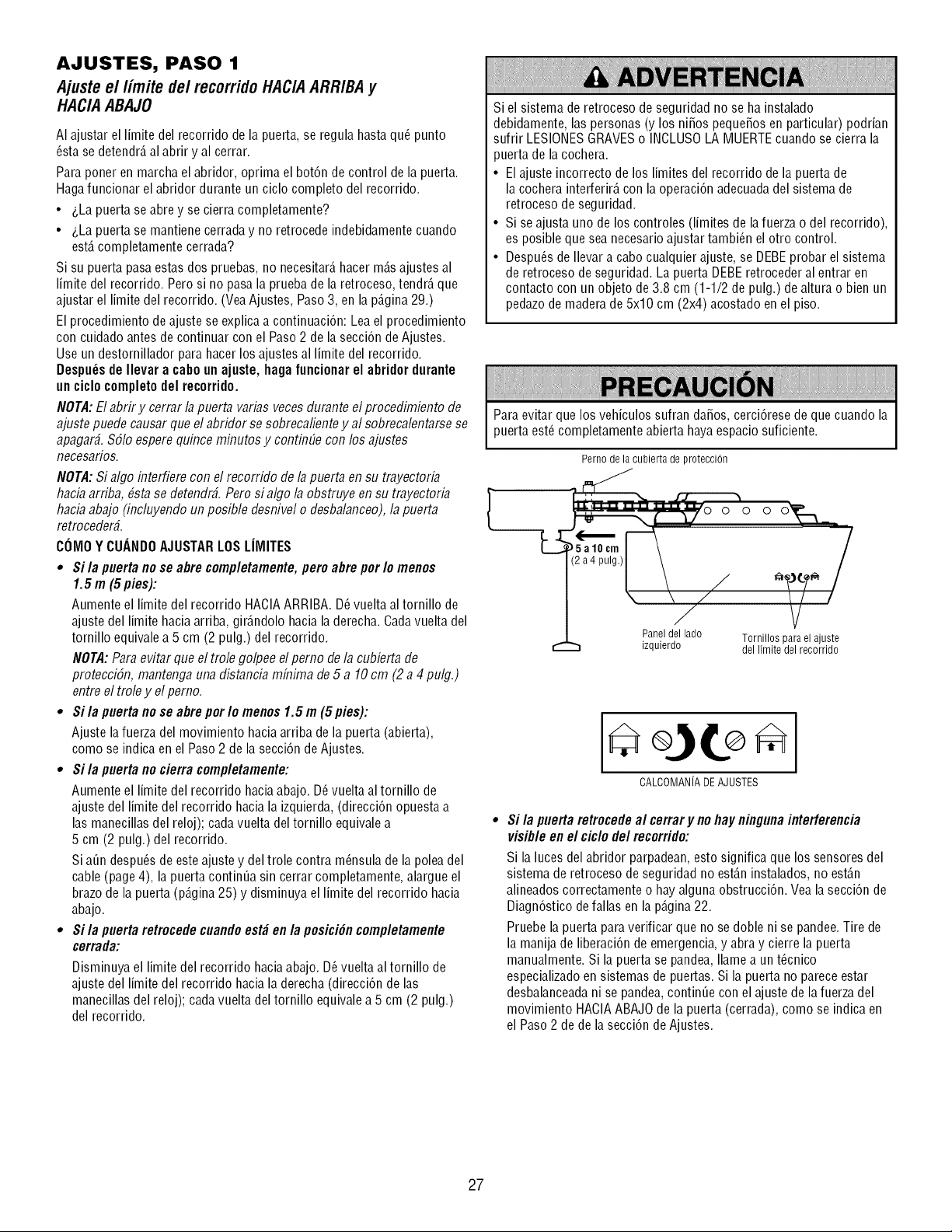
AJUSTES, PASO 1
Ajuste e//imite de/recorrido HACIA ARRIBA y
HACIA ABAJO
AI ajustar el limite del recorrido de la puerta, se regula hasta qu6 punto
_sta se detendr_,al abrir y al cerrar.
Para poner en marcha el abridor, oprima el bot6n de control de la puerta.
Hagafuncionar el abridor durante un ciclo completo del recorrido.
• 4,Lapuerta se abre y se cierra completamente?
• 4,Lapuerta se mantiene cerraday no retrocede indebidamente cuando
est,. completamente cerrada?
Si su puerta pasaestas dos pruebas, no necesitar_,hacer m_.sajustes al
limite del recorrido. Pero si no pasa la prueba de la retroceso, tendr_,que
ajustar el limite del recorrido. (Vea Ajustes, Paso 3, en la p_.gina29.)
El procedimiento de ajuste se explica a continuaci6n: Lea el procedimiento
con cuidado antes de continuar con el Paso2 de la secci6n de Ajustes.
Use un destornillador para hacer los ajustes al limite del recorrido.
Despu_sde Ilevar a cabo un ajuste, haga funcionarel abridor durante
un ciclo completodel recorrido.
NOTA:El abrir y cerrar lapuerta varias veces durante el procedimiento de
ajuste puede causar que el abridor se sobrecaliente y al sobrecalentarse se
apagar#. $51oespere quince minutos y continElecon los ajustes
necesafios.
NOTA:Si algo interfiere con el recorrido de lapuerta en su trayectoria
hacia arriba, #sta se detendr#. Pero si algo la obstruye en su trayectoria
hacia abajo (incluyendo un posible desnivel o desbalanceo),la puerta
retroceder_.
COIV]OY CUANDOAJUSTARLOSLIMITES
• Si/a puerta no se abre comp/etamente,pero abre por/o menos
1.5 m (5 pies):
Aumente el limite del recorrido HACIAARRIBA. D_vuelta al tornillo de
ajuste del limite haciaarriba, gir_.ndolo haciala derecha. Cadavuelta del
tornillo equivale a 5 cm (2 pulg.) del recorrido.
NOTA: Para evitar que el trole golpee el pemo de la cubierta de
protecciSn, mantenga una distancia mfiTimade 5 a 10 cm (2 a 4 pulg.)
entre el trole y el pemo.
• Si la puerta no se abre por Io menos 1.5 m (5 pies):
Ajuste lafuerza del movimiento hacia arriba de la puerta (abierta),
como se indica en el Paso2 de la secci6n de Ajustes.
• Si la puerta no cierra completamente:
Aumente el limite del recorrido hacia abajo. D_vuelta al tornillo de
ajuste del limite del recorrido hacia la izquierda, (direcci6n opuesta a
las manecillas del reloj); cadavuelta del tornillo equivale a
5 cm (2 pulg.) del recorrido.
Si a_n despu_sde esteajuste y del trole contra m_nsula de la polea del
cable (page 4), la puerta continua sin cerrar completamente, alargue el
brazo de la puerta (p_.gina25) y disminuya el limite del recorrido hacia
abajo.
• Si la puerta retrocede cuandoest_ en la posici6ncompletamente
cerrada:
Disminuya el limite del recorrido hacia abajo. D6vuelta al tornillo de
ajuste del limite del recorrido hacia la derecha (direcci6n de las
manecillas del reloj); cada vuelta del tornillo equivalea 5 cm (2 pulg.)
del recorrido.
Si el sistema de retroceso de seguridad no se ha instalado
debidamente, las personas (y los niSos pequeSosen particular) podrian
sufrir LESIONESGRAVESo INCLUSOLA MUERTEcuando se cierra la
puerta de la cochera.
• El ajuste incorrecto de los limites del recorrido de la puerta de
la cochera interferir_,con la operaci6n adecuada del sistema de
retroceso de seguridad.
• Si se ajusta uno de los controles (limites de lafuerza o del recorrido),
es posible que sea necesarioajustar tambi_n el otro control.
• Despu_s de Ilevar a cabo cualquier ajuste, se DEBEprobar el sistema
de retroceso de seguridad. La puerta DEBEretroceder al entrar en
contacto con un objeto de 3.8 cm (1-1/2 de pulg.) de altura o bien un
pedazode madera de 5x10 cm (2x4) acostado en el piso.
Para evitar que los vehiculos sufran daSos, cerci6rese de que cuando la
puerta est_ completamente abierta hayaespacio suficiente.
Perno de la cubierta de protecci(m
J
4-i...... .N
\ ",D,o o o o
5al0cm
__a 4 pulg.)
Paneldel lado
izquierdo
Tornillos para el ajuste
del limite del recorrido
CALCOMANJADEAJUSTES
Si /a puerta retrocede al cerrar y no hay ninguna interferencia
visib/e en e/cic/o de/recorrido:
Si la luces del abridor parpadean,esto significa que los sensores del
sistema de retroceso de seguridad no est_.ninstalados, no est_.n
alineados correctamente o hay alguna obstrucci6n. Vea la secci6n de
Diagn6stico de fallas en la p_.gina22.
Pruebe la puerta paraverificar que no se doble ni se pandee.Tire de
la manija de liberaci6n de emergencia, y abra y cierre la puerta
manualmente. Si la puerta se pandea, Ilame a un t_cnico
especializadoen sistemas de puertas. Si la puerta no pareceestar
desbalanceadani se pandea, continue con el ajuste de la fuerza del
movimiento HACIAABAJOde la puerta (cerrada), como se indica en
el Paso 2 de de la secci6n deAjustes.
27
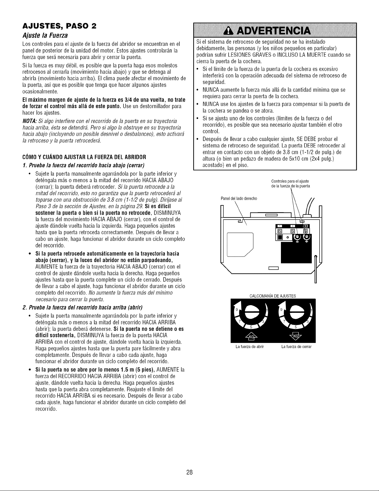
AJUSTES, PASO 2
Ajuste la Fuerza
Los controles para el ajuste de la fuerza del abridor se encuentran en el
panel de posterior de la unidad del motor. Estos ajustes controlar_.n la
fuerza que ser_.necesaria para abrir y cerrar la puerta.
Si la fuerza es muy d_bil, es posible que la puerta haga esos molestos
retrocesos al cerrarla (movimiento haciaabajo) y que se detenga al
abrirla (movimiento haciaarriba). El clima puede afectar el movimiento de
la puerta, asi que es posible que tenga que hacer algunos ajustes
ocasionalmente.
El m_ximo margende ajustede la fuerza es 3/4 de una vuelta, no trate
de forzar el controlm_s all_ de este punto. Use un destornillador para
hacer los ajustes.
NOTA: Si algo interfiere con el recorrido de la puerta en su trayectoria
hacia arriba, #sta se detendr_. Pero si algo la obstruye en su trayectoria
hacia abajo (incluyendo un posible desnivel o desbalanceo), esto acfivar_
la retroceso y la puerta retroceder_.
COMOY CUANDOAJUSTARLA FUERZADELABRIDOR
1. Pruebe /a fuerza de/recorrido hacia abajo (cerrar)
• Sujete la puerta manualmente agarr_.ndolapor la parte inferior y
det_ngala m_.so menos a la mitad del recorrido HACIAABAJO
(cerrar); la puerta deber_,retroceder. Si la puerta retrocede a la
mitad del recorrido, esto no garantiza que la puerta retroceder_ al
toparse con una obstrucciSn de 3.8 cm (1-1/2 de pulg). Dirfjase al
Paso3 de la secciSn de Ajustes, en la p_gina 29. Si es dificil
sostenerla puertao bien si la puerta no retrocede, DISMINUYA
la fuerza del movimiento HACIAABAJO (cerrar), con el control de
ajuste d_.ndolevuelta hacia la izquierda. Hagapeque5os ajustes
hasta que la puerta retroceda correctamente. Despu_s de Ilevar a
cabo un ajuste, haga funcionar el abridor durante un ciclo completo
del recorrido.
• Si la puertaretrocede automticamente en la trayectoria hacia
abajo (cerrar), y la lucesdel abridor no est_n parpadeando,
AUMENTEla fuerza de latrayectoria HACIAABAJO(cerrar) con el
control de ajuste d_.ndolevuelta hacia la derecha. Haga peque_os
ajustes hasta que la puerta complete un ciclo de cerrado. Despu_s
de Ilevar a cabo el ajuste, hagafuncionar el abridor durante un ciclo
completo del recorrido. No aumente la fuerza m_s del mfi7imo
necesario para cerrar la puerta.
2. Pruebe la fuerza de/recorrido hacia arriba (abrir)
• Sujete la puerta manualmente agarr_.ndolapor la parte inferior y
det_ngala m_.so menos a la mitad del recorrido HACIAARRIBA
(abrir); la puerta deber_,detenerse. Si la puerta no se detiene o es
dificil sostenerla, DISMINUYA la fuerza de la puerta HACIA
ARRIBA con el control de ajuste, d_.ndolevuelta hacia la izquierda.
Haga peque_osajustes hasta que la puerta pare f_.cilmentey abra
completamente. Despu_s de Ilevar a cabo cadaajuste, haga
funcionar el abridor durante un ciclo completo del recorrido.
• Si la puertano se abre pot Io menos 1.5 m (5 pies), AUMENTE la
fuerza del RECORRIDOHACIAARRIBA (abrir) con el control de
ajuste, d_.ndolevuelta hacia la derecha. Haga peque_osajustes
hasta que la puerta abra completamente. Reajuste el limite del
recorrido HACIAARRIBA si es necesario. Despu_s de Ilevar a cabo
cada ajuste, haga funcionar el abridor durante un ciclo completo del
recorrido.
Si el sistema de retroceso de seguridad no se ha instalado
debidamente, las personas (y los ni_os peque_os en particular)
podrian sufrir LESIONESGRAVESo INCLUSOLA MUERTEcuando se
cierra la puerta de la cochera.
• Si el limite de la fuerza de la puerta de la cochera es excesivo
interferir_, con la operaci6n adecuada del sistema de retroceso de
seguridad.
• NUNCAaumente la fuerza m_.sall_.de la cantidad minima que se
requiera para cerrar la puerta de la cochera.
• NUNCAuse los ajustes de lafuerza para compensar si la puerta de
la cochera se pandeao se atora.
• Si se ajusta uno de los controles (limites de la fuerza o del
recorrido), es posible que sea necesario ajustar tambi_n el otro
control.
• Despu_s de Ilevar a cabo cualquier ajuste, SE DEBEprobar el
sistema de retroceso de seguridad. La puerta DEBEretroceder al
entrar en contacto con un objeto de3.8 cm (1-1/2 de pulg.) de
altura (o bien un pedazo de madera de 5x10 cm (2x4 pulg.)
acostado) en el piso.
Controlespara el ajuste
de la fuerzade la puerta
CALCOMANIADE AJUSTES
La fuerza de abrir La fuerza de cerrar
28
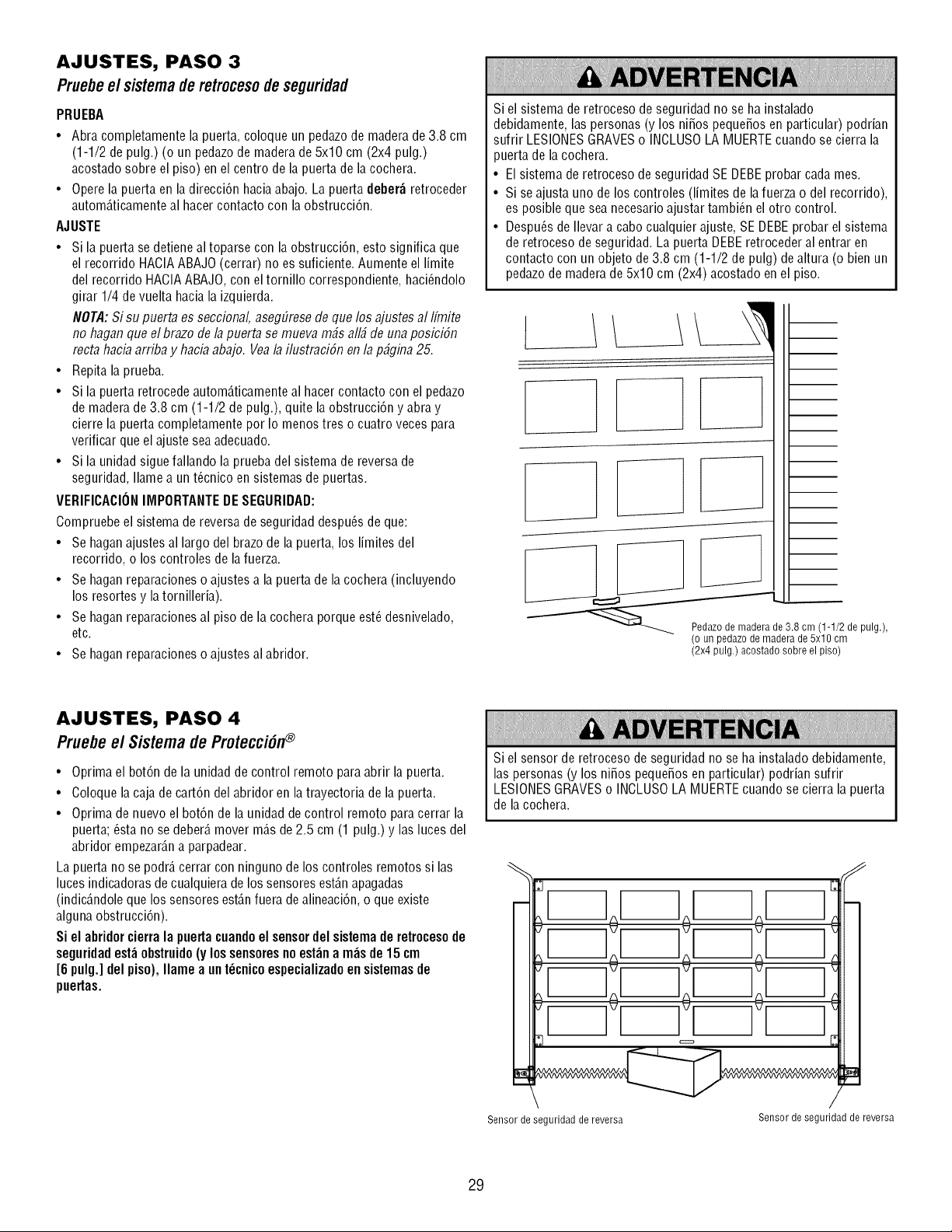
AJUSTES, PASO 3
Pruebee/sistemaderetrocesodeseguridad
PRUEBA
• Abra completamente la puerta, coloque un pedazode madera de3.8 cm
(1-1/2 de pulg.) (o un pedazode madera de 5x10 cm (2x4 pulg.)
acostado sobre el piso) en el centro de la puerta de la cochera.
• Operela puerta en la direcci6n hacia abajo. La puerta deber_ retroceder
autom_.ticamenteal hacer contacto con la obstrucci6n.
AJUSTE
• Si la puerta se detiene al toparse con la obstrucci6n, esto significa que
el recorrido HACIAABAJO (cerrar) no es suficiente. Aumente el limite
del recorrido HACIAABAJO, con el tornillo correspondiente, haci_ndolo
girar 1/4 de vuelta hacia la izquierda.
NOTA:Si su puerta es seccional, asegEiresede que los ajustes al Ifmite
no haganque el brazo de la puerta se mueva m_s all_ de unaposbi6n
recta hacb arriba y hacb abajo. Veala ilustraciSn en la p_gina 25.
• Repita la prueba.
• Si la puerta retrocede autom_.ticamenteal hacercontacto con el pedazo
de maderade 3.8 cm (1-1/2 de pulg.), quite la obstrucci6n y abra y
cierre la puerta completamente por Io menos tres o cuatro veces para
verificar que el ajuste sea adecuado.
• Si la unidad siguefallando la prueba del sistema de reversa de
seguridad, Ilame a un t_cnico en sistemas de puertas.
VERIFICACIONIMPORTANTEDESEGURIDAD:
Compruebe el sistema de reversa de seguridad despu_s de que:
• Se haganajustes al largo del brazo de la puerta, los limites del
recorrido, o los controles de lafuerza.
• Se haganreparaciones o ajustes a la puerta de la cochera (incluyendo
los resortes y la tornilleria).
• Se haganreparacionesal piso de la cochera porque est_desnivelado,
etc.
• Se haganreparaciones o ajustes al abridor.
Si el sistema de retroceso de seguridad no se ha instalado
debidamente, las personas (y los ni_os peque_osen particular) podrian
sufrir LESIONESGRAVESo INCLUSOLA MUERTEcuando se cierra la
puerta de la cochera.
• El sistema de retroceso de seguridad SE DEBEprobar cada mes.
• Si se ajusta uno de los controles (limites de lafuerza o del recorrido),
es posible que sea necesarioajustar tambi_n el otro control.
• Despu_s de Ilevar a cabo cualquier ajuste, SE DEBEprobar el sistema
de retroceso de seguridad. La puerta DEBEretroceder al entrar en
contacto con un objeto de 3.8 cm (1-1/2 de pulg) de altura (o bien un
pedazode madera de 5x10 cm (2x4) acostado en el piso.
L
1
_e 3.8 cm (1-1/2 de pulg.),
(o un pedazo de madera de 5x10 cm
(2x4 pulg.) acostado sobre el piso)
AJUSTES, PASO 4
Pruebeel Sistema de Protecci6n®
• Oprima el bot6n de la unidad de control remoto para abrir la puerta.
• Coloque lacaja de cart6n del abridor en latrayectoria de la puerta.
• Oprima de nuevo el bot6n de la unidad de control remoto para cerrar la
puerta; _sta no se deber_,mover m_.sde 2.5 cm (1 pulg.) y las luces del
abridor empezar_.na parpadear.
La puerta no se podr_,cerrar con ninguno de los controles remotos si las
luces indicadoras de cualquierade los sensores est_.napagadas
(indic_.ndoleque los sensores est_.nfuera de alineaci6n, o que existe
algunaobstrucci6n).
Si el abridorcierra la puertacuandoel sensordel sistemade retrocesode
seguridadest_ obstruido (y lossensoresno est_n a m_s de 15 cm
[6 pulg.] del piso), Ilame a unt_cnicoespecializadoen sistemasde
puertas.
Si el sensor de retroceso de seguridad no se ha instalado debidamente,
las personas (y los ni_os peque_osen particular) podrian sufrir
LESIONESGRAVESo INCLUSOLA MUERTEcuando se cierra la puerta
de la cochera.
Sensor de seguridad de reversa
J
/
Sensor de seguridad de reversa
29
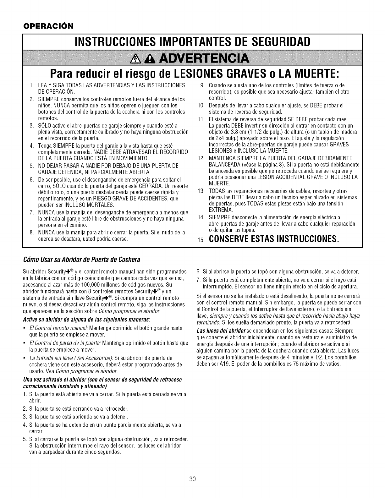
OPERACION
INSTRUCCIONESIMPORTANTESDE SEGURIDAD
Para reducirel riesgode LESIONESGRAVESo LAMUERTE:
1. LEA Y SIGATODASLAS ADVERTENCIASY LAS INSTRUCCIONES
DEOPERACION.
2. SIEMPRE conserve los controles remotos fuera del alcance de los
ni_os. NUNCApermita que los ni_os operen o jueguen con los
botones del control de la puerta de la cochera ni con los controles
remotos.
3. SOLOactive el abre-puertas de garaje siempre y cuando est_ a
plena vista, correctamente calibrado y no hayaninguna obstrucci6n
en el recorrido de la puerta.
4. Tenga SIEMPRE la puerta del garaje a lavista hasta que est_
completamente cerrada. NADIEDEBEATRAVESAREL RECORRIDO
DELA PUERTACUANDOEST/_ENMOVIMIENTO.
5. NO DEJAR PASARA NADIEPORDEBAJODEUNA PUERTADE
GARAJE DETENIDA,NI PARCIALMENTEABIERTA.
6. De ser posible, use el desenganche de emergencia para soltar el
carro, SOLOcuando la puerta del garaje est_ CERRADA.Un resorte
d_bil o roto, o una puerta desbalanceadapuedecaerse r_.piday
repentinamente, yes un RIESGOGRAVEDEACCIDENTES,que
pueden ser INCLUSOMORTALES.
7. NUNCAuse la manija del desenganchede emergencia a menos que
la entradaal garaje est_ libre de obstrucciones y no haya ninguna
persona en el camino.
8. NUNCAuse la manija para abrir o cerrar la puerta. Si el nudo de la
cuerda se desatara, usted podria caerse.
9. Cuando se ajusta uno de los controles (limites de fuerza o de
recorrido), es posible que sea necesarioajustar tambi_n el otro
control.
10. Despu_s de Ilevara cabo cualquier ajuste, se DEBEprobar el
sistema de reversa de seguridad.
11. El sistema de reversade seguridad SE DEBEprobar cada mes.
La puerta DEBEinvertir su direcci6n al entrar en contacto con un
objeto de 3.8 cm (1-1/2 de pulg.) de altura (o untabl6n de madera
de 2x4 pulg.) apoyado sobre el piso. El ajuste y la regulaci6n
incorrectas de laabre-puertas de garaje puedecausar GRAVES
LESIONESe INCLUSOLA MUERTE.
12. MANTENGASIEMPRELA PUERTADEL GARAJEDEBIDAMENTE
BALANCEADA(v_ase la p_.gina3). Si la puerta no est,. debidamente
balanceadaes posible que no retroceda cuando asi se requiera y
podria ocasionar una LESIONACCIDENTALGRAVEO INCLUSOLA
MUERTE.
13. TODASlas reparaciones necesariasde cables, resortes y otras
piezaslas DEBEIlevar a cabo un t_cnico especializadoen sistemas
de puertas, pues TODASestas piezas est_.nbajo una tensi6n
EXTREMA.
14. SIEMPREdesconecte la alimentaci6n de energia el_ctrica al
abre-puertas de garaje antes de Ilevar a cabo cualquier reparaci6n
o de quitar las tapas.
15.CONSERVEESTASINSTRUCCIONES.
C#moUsarsuAbridordePuertadeCochera
Su abridor Security.I.® y el control remoto manual han sido programados
en la f_.bricacon un c6digo coincidente que cambia cada vezque se usa,
accesando al azar m_.sde 100,000 millones de c6digos nuevos. Su
abridor funcionar_,hasta con 8 controles remotos Security.I.® y un
sistema de entrada sin Ilave Security.I.®. Si compra un control remoto
nuevo, o si desea desactivar alg_n control remoto, siga las instrucciones
que aparecen en la secci6n sobre CSmoprogramar el abridor.
Active su abridor de alguna de/as siguientes maneras:
• El Control remoto manual: Mantenga oprimido el bot6n grande hasta
que la puerta se empiecea mover.
• El Control de pared de la puerta: Mantenga oprimido el bot6n hasta que
la puerta se empiece a mover.
• La Entradasin Ilave (VeaAccesofios): Si su abridor de puerta de
cochera viene con esteaccesorio, deber_,estar programado antes de
usarlo. Vea CSmoprogramar el abridor.
Una vezactivado el abridor (con el sensor de seguridadde retroceso
correctamenteinsta/adoy a/ineado)
1. Si la puerta est,.abierta se va a cerrar. Si la puerta est,. cerradase va a
abrir.
2. Si la puerta se est,. cerrando va a retroceder.
3. Si la puerta se est,. abriendo se va a detener.
4. Si la puerta se ha detenido en un punto parcialmente abierta, se va a
cerrar.
5. Sial cerrarse la puerta se top6 con alguna obstrucci6n, va a retroceder.
Si la obstrucci6n interrumpe el rayo del sensor, las luces del abridor
van a parpadear durante cinco segundos.
6. Sial abrirse la puerta setop6 con alguna obstruccidn, seva a detener.
7. Si la puerta est,. completamente abierta, no va a cerrar si el rayo est,.
interrumpido. El sensor no tiene ning_n efecto en el ciclo deapertura.
Si el sensor no se ha instalado o est,. desalineado, la puerta no se cerrar_.
con el control remoto manual. Sin embargo, la puerta se puedecerrar con
el Control de la puerta, el Interruptor de Ilave externo, o la Entradasin
Ilave, siempre y cuando los active hasta que el recorrido hacia abajo haya
terminado. Si los suelta demasiado pronto, la puerta va a retroceder&
Las lucesde/abridorse encender_.nen los siguientes casos: Siempre
que conecte el abridor inicialmente; cuando se restaura el suministro de
energia despu_sde una interrupcidn; cuando el abridor se activa,o si
alguien camina por la puerta de la cochera cuando est,. abierta. Las luces
se apagan autom_.ticamentedespu_sde 4 minutos y 1/2. Los bombillos
deben ser A19. El poder de la bombillos es 75 m_ximo devatios.
3O
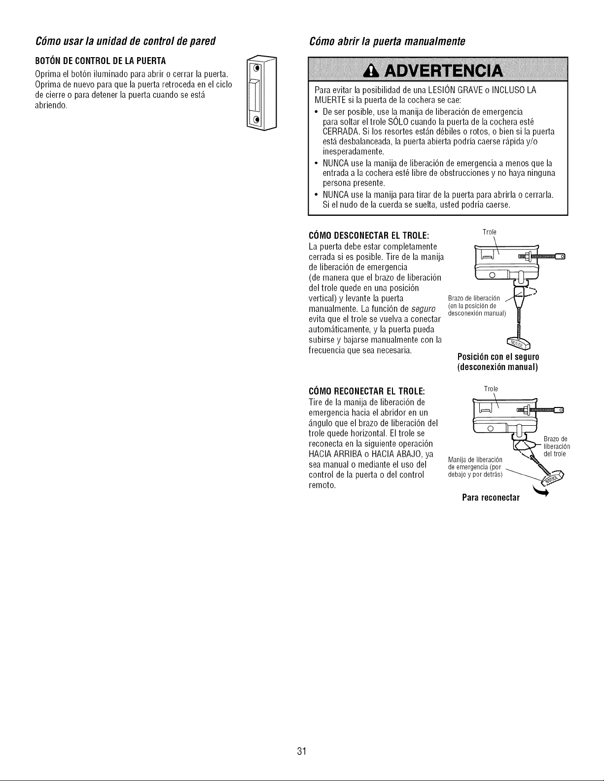
C6mousar/a unidadde contro/de pared
BOTONDE CONTROLDE LA PUERTA
Oprima el bot6n iluminado para abrir o cerrar la puerta.
Optima de nuevo para que la puerta retroceda en el ciclo
de cierre o para detener la puerta cuando se est,.
abriendo.
C6mo abrir /a puerta manua/mente
Para evitar la posibilidad de una LESIONGRAVEo INCLLISOLA
MUERTEsi la puerta de la cochera se cae:
• De ser posible, use la.manila de liberaci6n de emergencia
para soltar eltrole SOLOcuando la puerta de la cochera est_
CERRADA.Si los resortes est_.nd_biles o rotos, o bien si la puerta
est,.desbalanceada,la puerta abierta podria caerser_.piday/o
inesperadamente.
• NUNCAuse la manila de liberaci6n de emergencia a menos que la
entradaa la cochera est_ libre de obstrucciones y no hayaninguna
persona presente.
• NUNCAuse la manila para tirar de la puerta para abrirla o cerrarla.
Si el nudo de la cuerda se suelta, usted podria caerse.
COMODESCONECTAREL TROLE:
La puerta debe estar completamente
cerrada si es posible. Tire de la manila
de liberaci6nde emergencia
(de manera que el brazo de liberaci6n
del trole quede en una posici6n
vertical) y levante la puerta
manualmente. La funci6n de seguro
evita que el trole se vuelva a conectar
autom_.ticamente,y la puerta pueda
subirse y bajarse manualmente con la
frecuencia que sea necesaria.
COiVIORECONECTARELTROLE:
Tire de la manila de liberaci6n de
emergencia hacia el abridor en un
_.nguloque el brazo de liberaci6ndel
trole quede horizontal. El trole se
reconecta en la siguiente operaci6n
HACIAARRIBA o HACIAABAJO, ya
sea manual o mediante el uso del
control de la puerta o del control
remoto.
Trole
desconexi6nmanual)
Posici6n con el securo
(desconexi6nmanual)
Trole
_!n
Manila de liberaci0n
de emergencia (por _ _,.
debajo y por detr&s) -__
Para reconectar %'_
31
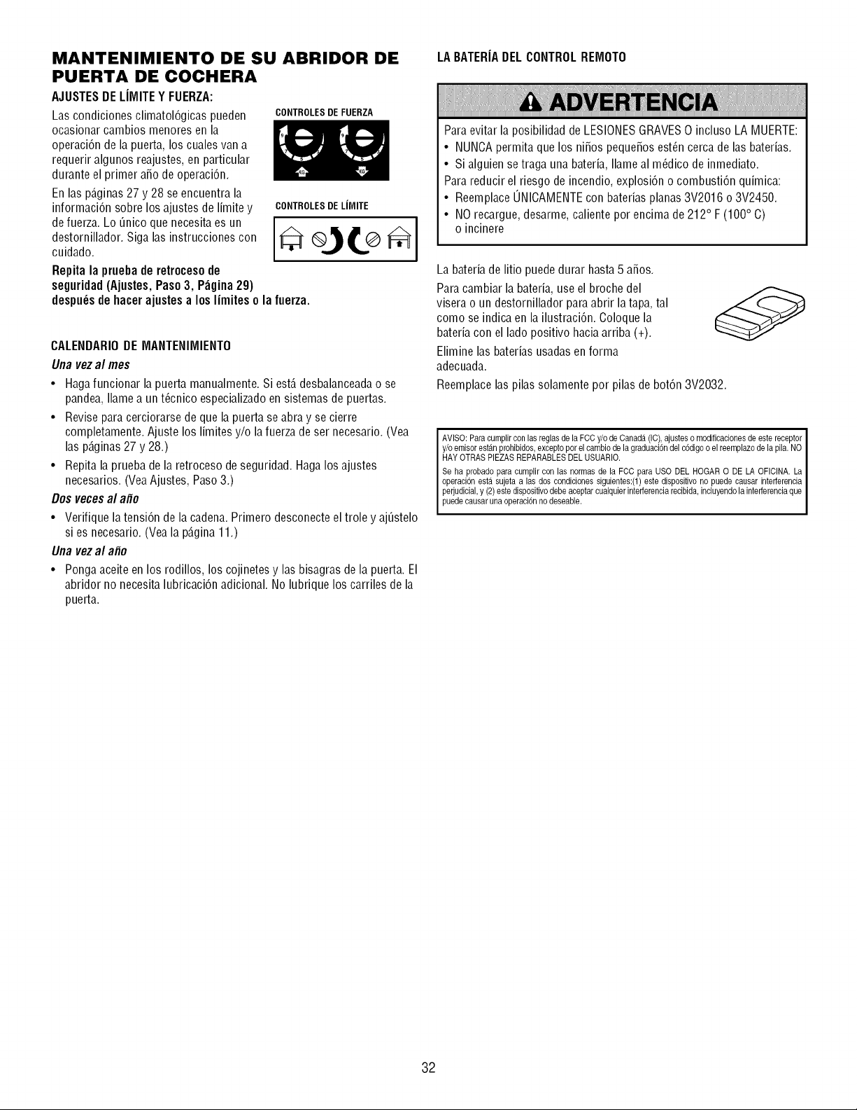
MANTENIMIENTO DE SU ABRIDOR DE
PUERTA DE COCHERA
AJUSTESDE LIMITE Y FUERZA:
Las condiciones climatol6gicas pueden CONTROLESDEFUERZA
ocasionar cambios menores en la
operaci6n de la puerta, los cuales van a
requerir algunos reajustes, en particular
durante el primer afio de operaci6n.
En las p_.ginas27 y 28 se encuentra la
informaci6n sobre los ajustes de limite y
de fuerza. Lo _nico que necesita es un
destornillador. Siga las instrucciones con
cuidado.
Repita la prueba de retrocesode
seguridad(Ajustes, Paso 3, P_gina 29)
despu_sde hacer ajustesa los limites o la fuerza.
CONTROLESDELilVIITE
CALENDARIODE MANTENIMIENTO
Una vezal mes
• Hagafuncionar la puerta manualmente. Si est,. desbalanceadao se
pandea, Ilamea un t@nico especializadoen sistemas de puertas.
• Revisepara cerciorarse de que la puerta se abra y se cierre
completamente. Ajuste los limites y/o la fuerza de ser necesario. (Vea
las p_.ginas27 y 28.)
• Repitala prueba de la retroceso de seguridad. Haga los ajustes
necesarios. (YeaAjustes, Paso 3.)
Dos veces al afio
• Verifique la tensi6n de la cadena.Primero desconecte el trole y aj_stelo
si es necesario. (Vea la p_.gina11.)
Una vezal afio
• Pongaaceite en los rodillos, los cojinetes y las bisagras de la puerta. El
abridor no necesita lubricaci6n adicional. No lubrique los carriles de la
puerta.
LA BATERIADEL CONTROLREMOTO
Para evitar la posibilidad de LESIONESGRAVES0 incluso LA MUERTE:
• NUNCApermita que los nifios peque_os est_n cerca de las baterias.
• Si alguien se traga una bateria, Ilameal m_dico de inmediato.
Para reducir el riesgo de incendio, explosi6n o combusti6n quimica:
• ReemplaceONICAMENTEcon baterias planas3V2016 o 3V2450.
• NO recargue, desarme, caliente por encima de 212° F (100° C)
o incinere
La bateria de litio puededurar hasta 5 afios.
Para cambiar la bateria, useel broche del
visera o un destornillador para abrir la tapa, tal
como se indica en la ilustraci6n. Coloque la
bateria con el lado positivo haciaarriba (+).
Elimine las baterias usadas en forma
adecuada.
Reemplacelas pilas solamente por pilas de bot6n 3V2032.
AVISO: Para cumplir con las reglas de la FCC y/o de Canada (IC), ajustes o modificaciones de este receptor I
y/o emisor est_inprohibidos, excepto por el cambio de la graduaci6n del c6digo o el reemplazo de la pila. NO I
HAY OTRAS PIEZAS REPARABLES DEL USUARIO. I
Seha probadopara cumplircon las normasde la FCC para USO DELHOGARO DE LA OFICINA.La I
operaci6n est,1 sujeta alas dos condiciones siguientes:(1) este dispositivo no puede causar interferencia I
perjudicial,y (2)estedispositivodebeaceptarcualquierinterferenciarecibida,incluyendola interferenciaque I
puede causar una operaci6n no deseable. I
I
32
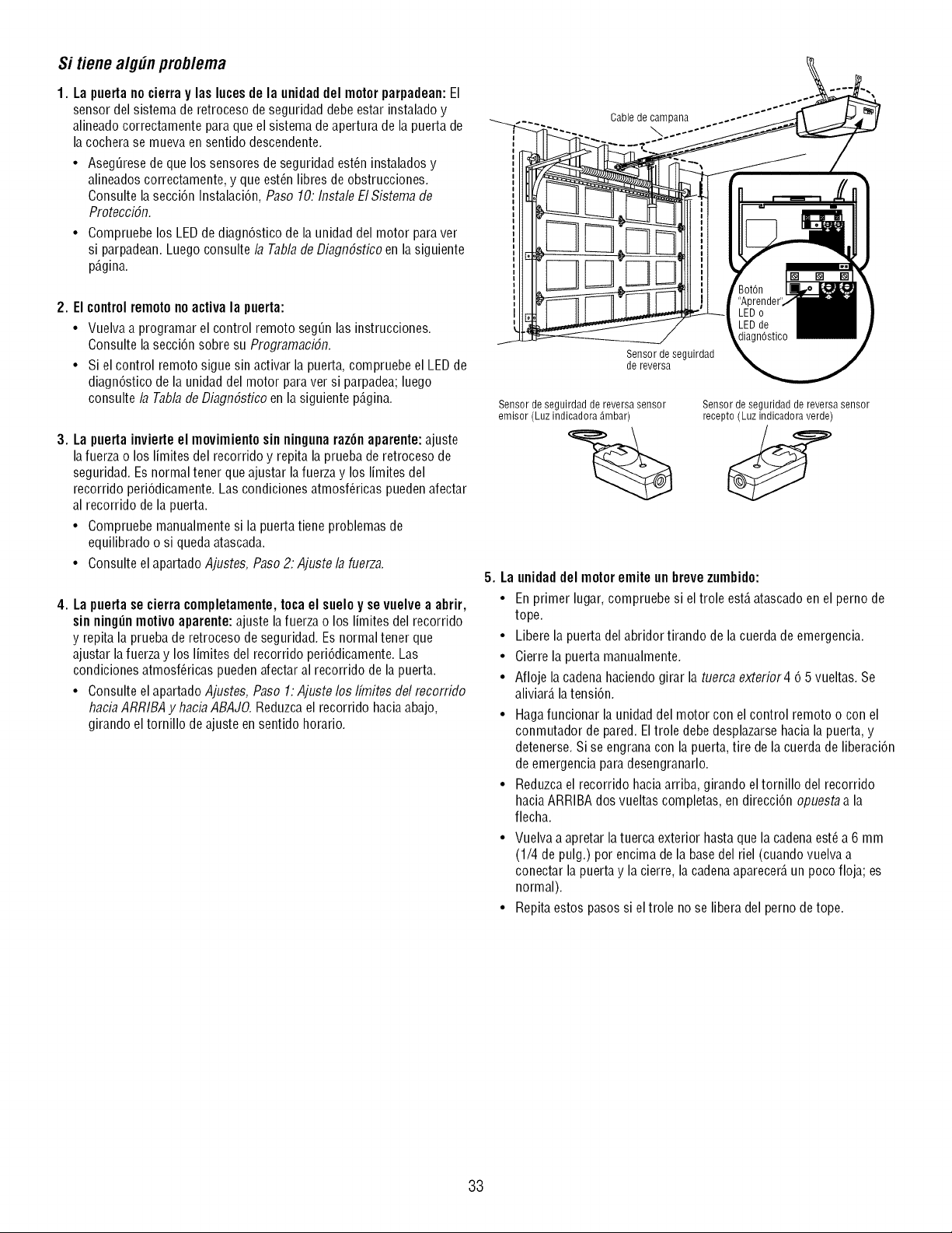
Si tiene alg_n prob/ema
1. La puerta no cierra y las luces de la unidad del motorparpadean:El
sensor del sistema de retroceso de seguridad debe estar instalado y
alineadocorrectamente para que el sistema de apertura de la puerta de
la cochera se mueva en sentido descendente.
• Aseg_rese de que los sensores de seguridad est_n instalados y
alineados correctamente, y que est_n libres de obstrucciones.
Consulte la secci6n Instalaci6n, Paso 10: Instale EISistema de
Protecci6n.
• Compruebe los LEDde diagn6stico de la unidad del motor para ver
si parpadean. Luego consulte la Tabla deDiagn6stico en la siguiente
p_.gina.
2. El controlremoto no activa la puerta:
• Vuelva a programar el control remoto seg_n las instrucciones.
Consulte la secci6n sobre su Programaci6n.
• Si el control remoto sigue sin activar la puerta, compruebe el LEDde
diagn6stico de la unidad del motor para ver si parpadea; luego
consulte/a Tab/ade Diagn6stico en la siguiente p_.gina.
3. La puerta invierte el movimiento sin ninguna raz6n aparente: ajuste
lafuerza o los limites del recorrido y repita la prueba de retroceso de
seguridad. Es normal tener que ajustar la fuerza y los limites del
recorrido peri6dicamente. Las condiciones atmosf@icas pueden afectar
al recorrido de la puerta.
• Compruebe manualmente si la puerta tiene problemas de
equilibrado o si queda atascada.
• Consulte el apartado Ajustes, Paso 2: Ajuste/a fuerza.
4. La puerta se cierra completamente, toca el suelo y se vuelve a abrir,
sin ningun motivo aparente: ajuste la fuerza o los limites del recorrido
y repita la prueba de retroceso de seguridad. Es normal tener que
ajustar la fuerza y los limites del recorrido peri6dicamente. Las
condiciones atmosf@icas pueden afectar al recorrido de la puerta.
• Consulte el apartado Ajustes, Paso 1: Ajuste los Ifmites del recorrido
haciaARR/BA y haciaABAJO.Reduzca el recorrido haciaabajo,
girando el tornillo de ajuste en sentido horario.
Cable de campana
Sensor de seguirdad
de reversa
Sensor de seguirdad de reversa sensor
emisor (Luz indicadora _mbar)
Sensor de seguridad de reversa sensor
recepto (Luz indicadora verde)
U
5. La unidaddel motor emite un brevezumbido:
• En primer lugar, compruebe si el trole est,.atascado en el perno de
tope.
• Libere la puerta del abridor tirando de la cuerda de emergencia.
• Cierre la puerta manualmente.
• Afloje la cadenahaciendo girar la tuerca exterior4 6 5 vueltas. Se
aliviar_,latensi6n.
• Hagafuncionar la unidad del motor con el control remoto o con el
conmutador de pared. El trole debe desplazarsehacia la puerta, y
detenerse. Si se engranacon la puerta, tire de la cuerda de liberaci6n
de emergencia para desengranarlo.
• Reduzca el recorrido haciaarriba, girando el tornillo del recorrido
hacia ARRIBA dos vueltas completas, en direcci6n opuesta a la
flecha.
• Vuelva a apretar latuerca exterior hasta que la cadenaest_ a 6 mm
(1/4 de pulg.) por encima de la base del riel (cuando vuelva a
conectar la puerta y la cierre, la cadenaaparecer_,un poco floja; es
normal).
• Repita estos pasos si eltrole no se libera del perno de tope.
33
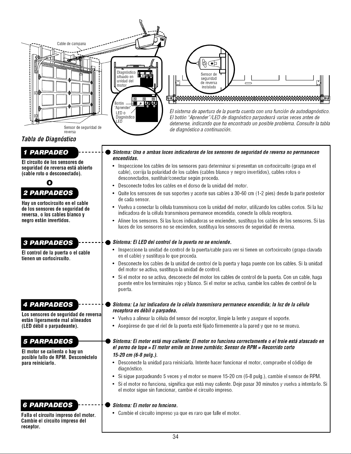
Cable de campana
Sensor de seguridad de
reversa
Tab/a de Oiagn6stico
El circuito de los sensoresde
seguridadde reversaest_ abierto
(cable rotoo desconectado).
0
Hayuncortocircuitoen el cable
delossensoresdeseguridadde
reversa,o loscablesblancoy
negroest_ninvertidos.
Elcontroldela puertao el cable
tienenuncortocircuito.
Lossensoresdeseguridaddereversa
est_nligeramenterealalineados
(LEDd_bilo parpadeante).
Elmotorsecalientao hayun
posiblefallo deRPM.Descon_ctelo
parareiniciarlo.
Fallael circuitoimpresodel motor.
Cambieel circuitoimpresodel
receptor.
Elsbtema de apertura dela puerta cuenta con una funciSn de autodiagn6stico.
Elbot6n "Aprender"/LED de diagn6stico parpadear_ varias veces antes de
detenerse, indicando que ha encontrado unposible problem& Consulte la tabla
de diagn6stico a continuaci6n.
• Sintoma: Unao ambas/uces indicadorasde los sensores de seguridad de reversa no permanecen
encendidas.
• Inspeccione los cables de los sensores para determinar si presentan un cortocircuito (grapa en el
cable), corrija la polaridad de los cables (cables blanco y negro invertidos), cables rotos o
desconectados, sustituir/conectar segQnproceda.
• Desconectetodos los cables en el dorso de la unidad del motor.
• Quite los sensores de sus soportes y acorte sus cablesa 30-60 cm (1-2 pies) desde la parte posterior
de cadasensor.
• Vuelva a conectar la c_lulatransmisora con la unidad del motor, utilizando los cables cortos. Si la luz
indicadora de la c_lula transmisora permaneceencendida,conecte la c_lula receptora.
• Alinee los sensores. Si las luces indicadoras se encienden, sustituya los cables de los sensores. Si las
luces de los sensores no se encienden,sustituya los sensores de seguridad de reversa.
• Sintoma: El LED de/control de la puerta no se enciende.
• Inspeccione la unidad de control de la puerta/cable paraver si tienen un cortocircuito (grapa clavada
en el cable) y sustituya Io que proceda.
• Desconectelos cables de la unidad de control de la puerta y haga puente con los cables. Si la unidad
del motor se activa, sustituya la unidad de control.
• Si el motor no se activa, desconectedel motor los cables de control de la puerta. Con un cable, haga
puente entre los terminales rojo y blanco. Si el motor se activa, cambie los cables de control de la
puerta.
• Sintoma:La/uz indicadorade/a c#/u/atransmisorapermaneceencendida;/a/uzde/a c#/u/a
receptoraesd_bfloparpadea.
• Vuelvaaalinearla c_luladelsensordel receptor,limpiela lentey asegureel soporte.
• AsegQresedequeel rieldelapuertaest_fijadofirmementea laparedy quenose mueva.
Sintoma: El motorest_ muy ca/iente; El motor no funciona correctamenteo el tro/e est_ atascadoen
el perno de tope = El motor emite un breve zumbido;Sensor de RPM = Recorrido corto
15-20 cm (6-8 pu/g.).
• Desconectela unidad para reiniciarla. Intente hacer funcionar el motor, compruebe el c6digo de
diagn6stico.
• Si sigue parpadeando 5 vecesy el motor se mueve 15-20 cm (6-8 pulg.), cambie el sensor de RPM.
• Si el motor no funciona, significa que est,.muy caliente. Dejepasar 30 minutos y vuelva a intentarlo. Si
el motor sigue sin funcionar, cambie el circuito impreso.
• Sintoma: El motorno funciona.
• Cambie el circuito impreso ya que es raro que falle el motor.
34
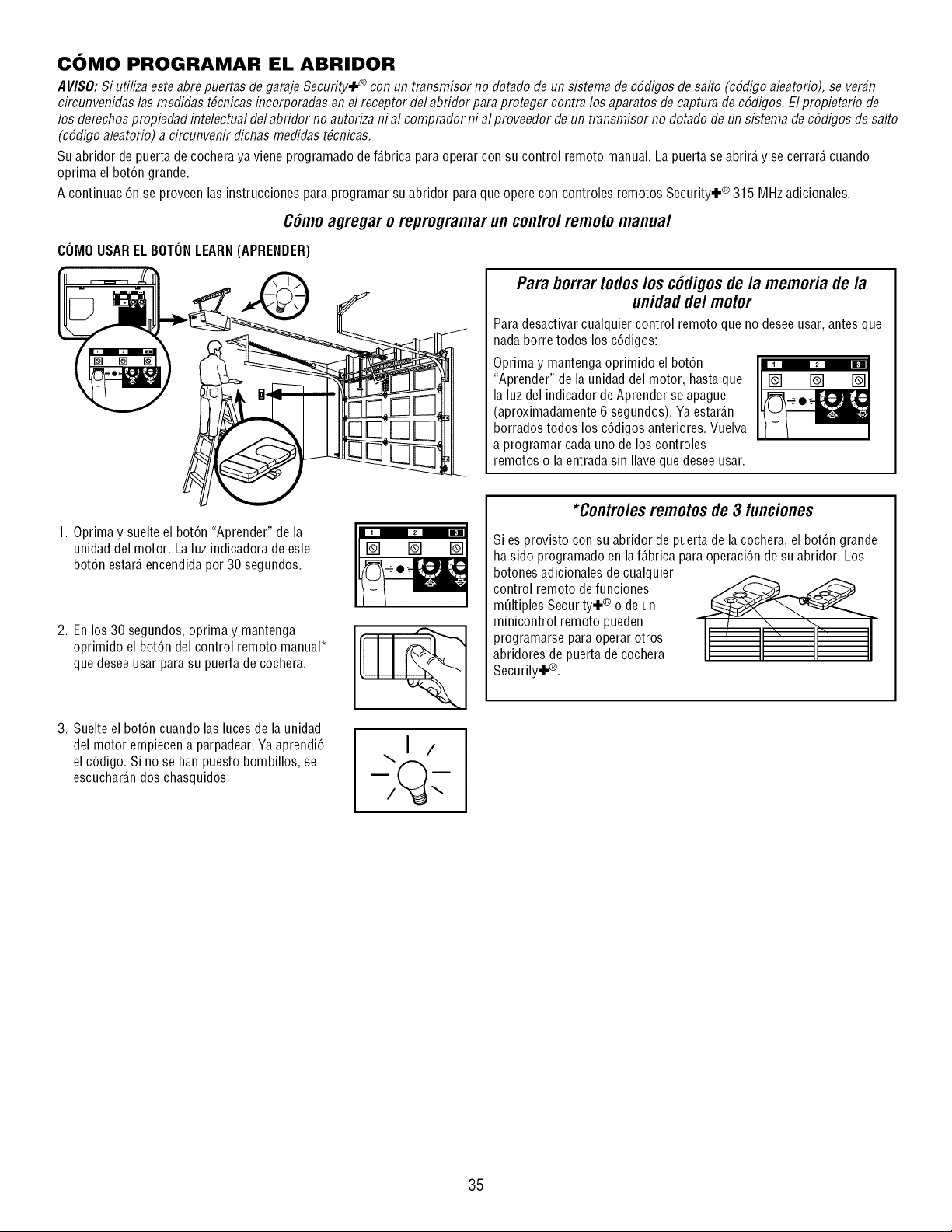
COMO PROGRAMAR EL ABRIDOR
A VISO:Si utiliza este abre puertas de garaje Security,F _ con un transmisor no dotado de un sistema de c6digos de salto (c6digo aleatorio), se ver_n
circunvenidas las medidas t_cnicas incorporadas en el receptor del abridor paraproteger contra los aparatos de captura de c6digos. Elpropietario de
los derechos propiedad intelectual del abridor no autoriza ni al comprador ni al proveedor de un transmisor no dotado de un sistema de c6digos de salto
(c6digo aleatorio) a circunvenir dichas medidas t_cnicas.
Su abridor de puerta decochera ya viene programado de f_.bricaparaoperar con su control remoto manual. La puerta se abrir_,y se cerrar_,cuando
oprima el bot6n grande.
A continuaci6n se proveen las instrucciones para programar su abridor para que opere con controles remotos Security.I.® 315 MHz adicionales.
C6moagregar o reprogramarun contro/remotomanua/
COMOUSAR EL BOTONLEARN(APRENDER)
Para borrar todos/os c6digosde la memoria de la
unidad de/motor
Para desactivar cualquier control remoto que no desee usar, antes que
nada borre todos los c6digos:
Oprima y mantenga oprimido el bot6n
"Aprender" de la unidad del motor, hasta que []
la luz del indicador de Aprender se apague
(aproximadamente 6 segundos). Ya estar_.n
borrados todos los c6digos anteriores. Vuelva
a programar cada uno de los controles
remotos o la entrada sin Ilave que desee usar.
1. Oprima y suelte el bot6n "Aprender" de la
unidad del motor. La luz indicadora de este
bot6n estar_,encendida por 30 segundos.
2. En los 30 segundos, oprima y mantenga
oprimido el bot6n del control remoto manual*
que desee usar para su puerta de cochera.
3. Suelte el bot6n cuando las luces de la unidad
del motor empiecen a parpadear. Ya aprendi6
el c6digo. Si no se han puesto bombillos, se
escuchar_.ndos chasquidos.
\1 /
*Contro/esremotosde 3 funciones
Si es provisto con su abridor de puerta de la cochera, el bot6n grande
ha sido programado en laf_.bricapara operaci6n de su abridor. Los
botones adicionales decualquier
control remoto de funciones
mQItiples Security.I.® o de un
minicontrol remoto pueden
programarse para operar otros
abridores de puerta de cochera
Security.I.®.
35
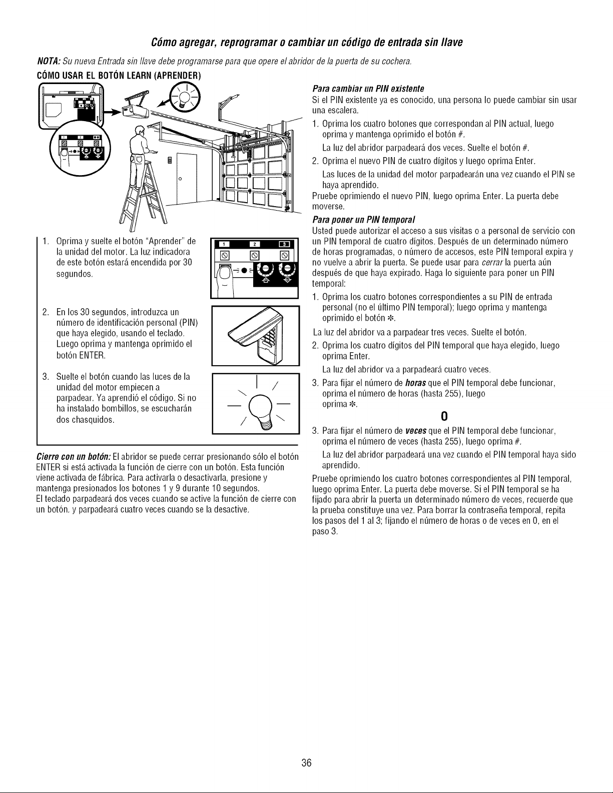
C6moagregar, reprogramaro cambiar un c6digode entradasin l/ave
NOTA:Su nueva Entradasin Ilave debe programarse para que opere el abridor de la puerta de su cochera.
COMOUSAR EL BOTONLEARN(APRENDER)
.
Oprima y suelte el bot6n "Aprender" de
la unidad del motor. La luz indicadora
de este bot6n estar_,encendida por 30
segundos.
.
.
En los 30 segundos, introduzca un
nQmero de identificaci6n personal (PIN)
que hayaelegido, usando elteclado.
Luego oprima y mantenga oprimido el
bot6n ENTER.
Suelte el bot6n cuando las luces de la
unidad del motor empiecen a
parpadear. Ya aprendi6 el c6digo. Si no
ha instalado bombillos, se escuchar_.n
dos chasquidos.
I /
Cierre conun bot6n: El abridor se puede cerrar presionando s61oel bot6n
ENTERsi est,.activada lafunci6n de cierre con un bot6n. Esta funci6n
vieneactivada de f_.brica.Para activarla o desactivarla, presione y
mantenga presionados los botones 1 y 9 durante 10 segundos.
Elteclado parpadear_,dos veces cuando se active la funci6n de cierre con
un bot6n, y parpadear_,cuatro veces cuando se la desactive.
Para cambiar un PIN existente
Si el PIN existente ya es conocido, una persona Io puedecambiar sin usar
una escalera.
1. Oprima los cuatro botones que correspondan al PIN actual, luego
oprima y mantenga oprimido el bot6n #.
La luz del abridor parpadear_,dos veces. Suelte el bot6n #.
2. Oprima el nuevo PIN de cuatro digitos y luego oprima Enter.
Las luces de la unidad del motor parpadear_.nuna vez cuando el PIN se
hayaaprendido.
Pruebe oprimiendo el nuevo PIN, luego oprima Enter. La puerta debe
moverse.
Para poner un PIN temporal
Usted puedeautorizar el acceso a sus visitas o a personal de servicio con
un PIN temporal de cuatro digitos. Despu_s de un determinado nQmero
de horas programadas, o nQmero de accesos, este PIN temporal expira y
no vuelve a abrir la puerta. Se puede usar para cerrar la puerta aQn
despu_sde que haya expirado. Haga Io siguiente para poner un PIN
temporal:
1. Oprima los cuatro botones correspondientes a su PIN de entrada
personal (no el Qltimo PINtemporal); luego oprima y mantenga
oprimido el bot6n _.
La luz del abridor va a parpadeartres veces. Suelte el bot6n.
2. Oprima los cuatro digitos del PIN temporal que hayaelegido, luego
oprima Enter.
La luz del abridor va a parpadear_,cuatro veces.
3. Parafijar el n_mero defloras que el PINtemporal debe funcionar,
oprima el n_mero de horas (hasta 255), luego
oprima ¢.
0
3. Parafijar el n_mero de veces que el PIN temporal debe funcionar,
oprima el n_mero de veces (hasta 255), luego oprima #.
La luz del abridor parpadear_,una vez cuando el PIN temporal haya sido
aprendido.
Pruebe oprimiendo los cuatro botones correspondientes al PINtemporal,
luego oprima Enter. La puerta debe moverse. Si el PINtemporal se ha
fijado paraabrir la puerta un determinado nQmero de veces, recuerde que
la prueba constituye una vez. Para borrar la contrase5a temporal, repita
los pasos del 1 al 3; fijando el nQmero de horas o de veces en O,en el
paso3.
36
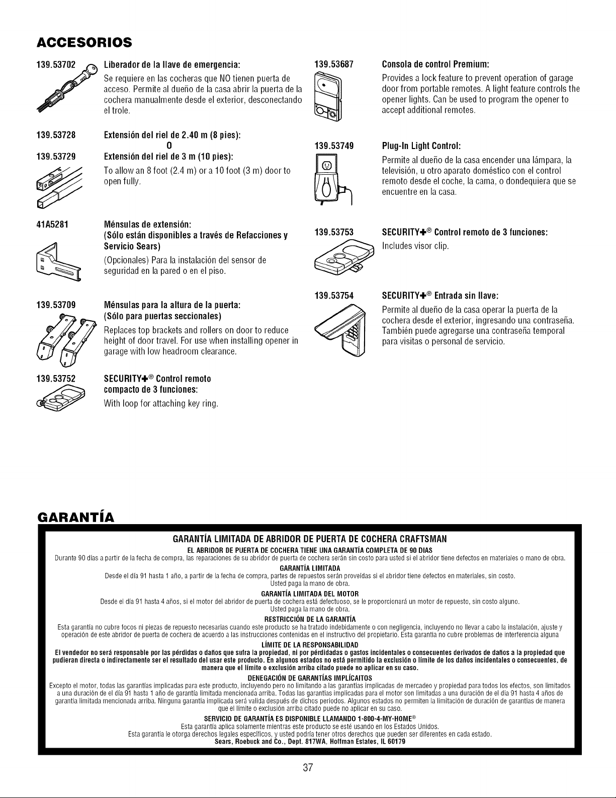
ACCESORIOS
Liberador de la Ilave de emergencia:
Se requiere en las cocheras que NOtienen puerta de
acceso. Permite al dueSode la casa abrir la puerta de la
cochera manualmente desde el exterior, desconectando
el trole.
139.53728
139.53729
41A5281
Extensi6ndelrielde2.40 m (8pies):
0
Extensi6ndelrielde3 m (10pies):
Toallowan8foot (2.4 m) or a 10foot (3 m) doorto
openfully.
M_nsulasdeextensi6n:
($61oest_ndisponiblesatray,sde Refaccionesy
ServicioSears)
(Opcionales)Parala instalaci6ndelsensorde
seguridaden laparedo enel piso.
139.53709
139.53752
M_nsulasparala alturade la puerta:
(S61opara puertasseccionales)
Replacestop bracketsand rollerson doorto reduce
heightof doortravel.Forusewheninstallingopenerin
garagewith low headroomclearance.
SECURITY+® Controlremoto
compactode3 funciones:
Withloopfor attachingkeyring.
139.53687
139.53749
139.53753
139.53754
Consola de controlPremium:
Providesa lock feature to prevent operation of garage
door from portable remotes. A light feature controls the
opener lights. Can be usedto program the opener to
accept additional remotes.
Plug-In Light Control:
Permite al dueSo de la casaencender una I_.mpara,la
televisidn, u otro aparato dom_stico con el control
remoto desde el coche, la cama, o dondequiera que se
encuentre en la casa.
SECURITY+® Controlremotode 3 funciones:
Includes visor clip.
SECURITY+® Entradasin Ilave:
Permite al due_o de la casa operar la puerta de la
cochera desde el exterior, ingresando unacontrase_a.
Tambi_n puede agregarse una contrase_a temporal
para visitas o personal de servicio.
GARANTiA
GARANTIALIMITADADEABRIDORDEPUERTADECOCHERACRAFTSMAN
EL ABRIDOR DE PUERTADE COCHERATIENE UNA GARANTiACOMPLETADE 90 DIAS
Durante 90 dias a partir de la fecha de compra, las reparaciones de su abridor de puerta de cochera ser_n sin costo para usted si el abridor tiene defectos en materiales o mano de obra.
GARANTJALIMITADA
Desde el dia 91 hasta 1 a_o, a partir de la fecha de compra, partes de repuestos ser_n proveidas si el abridor tiene defectos en materiales, sin costo.
Usted paga la mano de obra.
GARANTiALIIVlITADADEL MOTOR
Desdeel dia 91 hasta 4 a_os, si el motor del abridor de puerta de cochera est_ defectuoso, se le proporcionar_ un motor de repuesto, sin costo alguno.
Usted paga la mano de obra.
RESTRICCIONDE LA GARANTiA
Esta garantia no cubre focos ni piezas de repuesto necesarias cuando este producto se ha tratado indebidamente o con negligencia, incluyendo no Ilevar a cabo la instalaciOn, ajuste y
operaciOn de este abridor de puerta de cochera de acuerdo alas instrucciones contenidas en el instructivo del propietario. Esta garantia no cubre problemas de interferencia alguna
LiMITE DE LA RESPONSABILIDAD
El vendedor no ser_ responsable por las pdrdidas o dafios qne snfra la propiedad, ni por pdrdidadas o gastos incidentales o consecnentesderivados de dafios a la propiedad qne
pndieran directa o indirectamente ser el resnltado del nsar este prodncto. En algnnos estados noest_ permitido la exclnsidn o limite de los dafios incidentales o consecnentes, de
manera qne el limite o exclnsidn arriba citado pnede noaplicar en sn caso.
DENEGACIONDE GARANTIASIMPLICAITOS
Excepto el motor, todas las garantias implicadas para este producto, incluyendo pero no limitando alas garantias implicadas de mercadeo y propiedad para todos los efectos, son limitados
a una duraci6n de el dia 91 hasta 1 aSo de garantia limitada mencionada arriba. Todas las garantias implicadas para el motor son limitadas a una duraci6n de el dia 91 hasta 4 aSos de
garantia limitada mencionada arriba. Ninguna garantia implicada ser_ valida despuds de dichos periodos. Algunos estados no permiten la limitaci6n de duraci6n de garantias de manera
que el limite o exclusi6n arriba citado puede no aplicar en su caso.
SERVIClODE GARANTiAES DISPONIBLELLAMANDO 1-800-4-MY-HOME ®
Esta garantia aplica solamente mientras este producto se estd usando en los Estados Unidos.
Esta garantia le otorga derechos legales especificos, y usted podria tenor otros derechos que pueden ser diferentes en cada estado.
Sears, Roebuck and Co., Dept. 817WA, Holfman Estates, IL 60179
37

Your Home
For troubleshooting, product manuals and expert advice:
www.managemylife.com
For repair - in your home - of all major brand appliances,
lawn and garden equipment, or heating and cooling systems,
no matter who made it, no matter who sold it!
For the replacement parts, accessories and
owner's manuals that you need to do-it-yourself.
For Sears professional installation of home appliances
and items like garage door openers and water heaters.
1-800-4-MY-HOME ® (1-800-469-4663)
Call anytime, day or night (U.S.A. and Canada)
www.sears.com www.sears.ca
Our Home
For repair of carry-in items like vacuums, lawn equipment,
and electronics, call anytime for the location of your nearest
Sears Parts & Repair Service Center
1-800-488-1222 (U.S.A.) 1-800-469-4663 (Canada)
www.sears.com www.sears.ca
To purchase a protection agreement on a product serviced by Sears:
1-800-827-6655 (U.S.A.) 1-800-361-6665 (Canada)
Para pedir servicio de reparaci6n
a domicilio, y para ordenar piezas:
1-888-SU-HOGAR ®
(1-888-784-6427)
www.sears.com
Au Canada pour service en fran(_ais:
1-800-LE-FOYER Mc
(1-800-533-6937)
www.sears.ca
114A3612D
TM
® Registered Trademark / Trademark / SMService Mark of Sears, Roebuck and Co.
TM SM
® Mama Registrada / Marca de F_brica / Marca de Servicio de Sears, Roebuck and Co.
MC MD
Marque de commerce / Marque ddposde de Sears, Roebuck and Co.
©2011 Sears, Roebuck and Co.