Loading ...
Loading ...
Loading ...
ALPINE X-A90M/X-A70F/X-A90V 68-33122Z89-A (EN/FR/ES)
3-EN
EN
FR
ES
INSTALLATION
Due to the high power output of the X-A90M/
X-A70F/X-A90V considerable heat is produced
when the amplifier is in operation. For this reason,
the amplifier should be mounted in a location
which will allow for free circulation of air, such as
inside the trunk. For alternate installation locations,
please contact your authorized Alpine dealer.
Mount the amplifier before installing the
Terminal Cover (F)/(L)/(R).
1. Using the amplifier as a template, mark the four
screw locations.
2. Make sure there are no objects behind the
surface that may become damaged during
drilling.
3. Drill the screw holes.
4. Position the X-A90M/X-A70F/X-A90V over the
screw holes, and secure with four self-tapping
screws.
Self-Tapping Screws
M4 × 20 (Included)
Holes
(e.g. X-A90V)
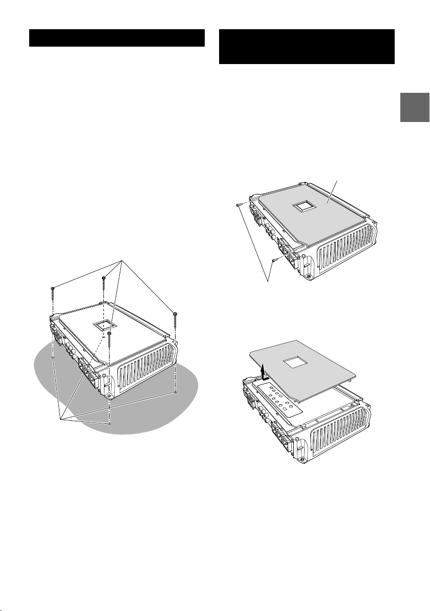
REMOVING THE TOP
COVER
When performing the Switch Setting, you must
remove the Top Cover.
• Remove the Top Cover before installing or after
removing the Terminal Cover (F). For details on
how to remove the Terminal Cover (F), see
”ATTACHING THE TERMINAL COVERS AND LOGO
PLATE” (page 4).
1. Remove the hexagon screws using the supplied
Hexagon Wrench (Small).
Top Cover
Hexagon Screws
(e.g. X-A90V)
2. Slide the Top Cover, and lift it to remove.
• Be sure not to damage the indicator area.
(e.g. X-A90V)
und to
ing
s in
pment
y, and it
ordance
nit in
e is
anty,
which
d States
r dealer
ge.
..............4
......1 SET
..............1
..............1
..............2
..............3
......1 SET
..............1
Loading ...
Loading ...
Loading ...