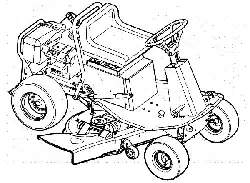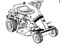
SafetyInstructions& Operator'sManual for
REARENGINERIDINGMOWER
SERIES23
f
Models
2811523BV (7800102)
2812523BVE (7800104)
3011523BV (7800103)
3012523BVE (7800105)
3317523BVE (7800254)
C2811523BV (7800363)
C2812523BVE (7800365)
C3011523BV (7800364)
C3012523BVE (7800366)
C3317523BVE (7800368)
\ 1
NOTE:Specifications are correctat time of printing and are subjectto changewithout notice.
* Actual sustained engine powerwill likely be lower dueto operating limitations and environmental factors. Please refer to 'EnginePower Rating Information' for
further details.
SNAPPERMcoo°ooo.o_.,_o_°_,
Manual No. 7102295 (I.R. 2/18/2008)
TP 100-5350-1R-RE-N

ThankYoufor purchasingthis quality-built Snapperproduct. We're pleasedthat you placedyour
confidenceinthe Snapperbrand.Whenoperatedand maintainedaccordingto the instructions in this
manual,your Snapperproduct will providemanyyearsof dependableservice.
Thismanualcontainssafety information to makeyou awareof the hazardsand risks associatedwith the
machineand how to avoidthem. This machineis designedand intendedonlyfor finish cutting of
establishedlawnsand is not intendedfor any other purpose.It is important that you readand understand
theseinstructions thoroughly beforeattemptingto start or operatethis equipment.Savethese
instructions for future reference.
PRODUCT REGISTRATION
IMPORTANT: KEEPTHIS INFORMATION FOR YOUR PERSONAL RECORDS
(Complete the following information on your Snapper purchase)
Date of Purchase
Retailer
Retailer'sPhoneNumber
Equipment
Model Number
Serial Number
Engine
Model .Type. Trim
It is veryimportantthatyouregisteryourpurchasewithSnapperto ensurewarrantycoverage.Please
mail yourproductregistrationcardto:
Snapper at P.O. Box 1379, IVIcDonough,Georgia 30253.
Oryou mayregisteronline at www.snapper.com.
Youcan contactusat ourwebsite,or if youwouldlike to speakwith a CustomerService
Representative,call usat the SnapperCustomerRelationsCenterat1-800-935-2967. Forfaster
servicepleasehaveyourSerial NumberandModel Numberavailable.
SNAPPERis a trademarkof
SimplicityManufacturing,Inc.
PortWashington,WI, USA.
Briggs& StrattonYardPower Products Group
Copyright© 2008, Briggs& StrattonCorporation
Milwaukee, WI, USA. All RightsReserved.
TableofContents
OperatorSafety ................................................ 2
Important OperatorSafety Instructions .................................. 2
Featuresand Controls ........................................... 5
Operation .................................................... 6
Pre-Start Checklist .................................................. 6
OperatorSeatAdjustment ............................................. 6
Starting Engine ..................................................... 7
Engaging Mower Blade ............................................... 9
EngagingWheel Drive ................................................ 9
Stopping Engine,Wheel Drive, Blade ................................... 10
Setting Park Brake ................................................. 11
Cutting HeightAdjustment ........................................... 11
ReverseLockout Mechanism ......................................... 12
Maintenance ................................................. 13
Service - After the First 5 Hours ....................................... 13
Service - Every25 Operating Hours .................................... 15
Service - Annually .................................................. 18
Service - EveryTwo Years............................................ 18
Storage .......................................................... 18
Removingthe FuelTank ............................................. 18
EngineAdjustments and Repairs ...................................... 19
Mower Deckand ComponentAdjustments ............................... 19
RearEngine Rider Drive Components ................................... 22
Mower Blade Replacement ........................................... 23
Mower Drive Belt Replacement........................................ 24
Battery ........................................................... 25
Snapper RearEngineRider Accessories ................................. 27
Service Schedule................................................... 28
Maintenance/ReplacementParts ....................................... 29
Troubleshooting............................................... 30
Warranty .................................................... 32
(o
D_
,.,,(.
(o
,,,,v..
,<=
"I"1
CD
CD
,-1
€')
(o
mo
,-1
(o
,-1
,-1
co
CD
,,,,v..
,,,-z
WARNING
Batteryposts, terminals and relatedaccessoriescontain
lead and lead compounds, chemicals known to the Stateof
Californiato cause cancer and birth defects or other
reproductiveharm. Wash handsafter handling.
WARNING
Engineexhaust, some of its constituents, and certain
vehicle components contain or emit chemicals known to
the State of California to causecancer or other reproductive
harm.
,--l-
eD
x,.,
ImportantOperatorSafetyInstructions
,&
WARNING:This powerful cutting machine is capableof amputating hands and feet and can throw objects
that cancause injury and damage! Failureto comply with the following SAFETYinstructions could result in
serious injury or deathto the operator or other persons. Theowner ofthe machine must understandthese
instructions and must allow only persons who understand these instructions to operatemachine. Each
person operating the machine must be of sound mind and body and must not be underthe influence of any
substance,which might impair vision, dexterity or judgment. If you haveany questions pertainingto your
machine which your dealercannot answerto your satisfaction, call or write the Customer Service
Department at SNAPPER,McDonough, Georgia30253. Phone:(1-800-935-2967).
Protection for Children
Tragic accidents canoccur if the operator is not alert to the
presenceof children. Children are often attracted to the
machine andthe mowing activity. Children who havebeen
given rides in the past may suddenly appear in the mowing
areafor another ride and be run over or backedover by the
machine.Never assumethat children will remain whereyou
last saw them.
1. KEEPchildren out of the mowing area and under the
watchful careof a responsible adult other than the operator.
2. DONOTallow children in yard when machine is operated
(evenwith the bladeOFF).
3. DONOTallow children or others to ride on machine,
attachmentsor towed equipment (evenwith the blades
OFF).They may fall and be seriously injured.
4. DONOTallow pre-teenagechildren to operate machine.
5.ALLOW only responsible adults & teenagerswith mature
judgment under close adult supervision to operate machine.
6. DONOToperatebladesin reverse.STOPBLADES.LOOK
and SEEbehind and down for children, pets and hazards
beforeand while backing.
7. USEEXTRACAREwhen approaching blind corners,
shrubs, trees, or other objects that may obscure vision.
Protection against Tipovers
Slopesare a major factor relatedto loss-of-control and tip-
overaccidents, which can result in severe injury or death.
All slopes require extra CAUTION.If you cannot back up the
slopeor if you feel uneasyon the slope, DONOTmow it.
Useextra care with grass catchers or other attachments;
these affect the handling and the stability of the machine.
Referto the Slope Guideat the end of this manual.
1. DONOToperatemachine on slopes exceeding15
degrees(27% grade).
2. ExerciseEXTREMECAUTIONon slopes above10
degrees(18% grade).Turn bladesOFFwhentraveling
uphill. Usea slow speedand avoidsudden or sharp turns.
3. DONOToperatemachine back and forth acrossface of
slopes.Operateup and down. Practiceon slopes with
bladesoff.
4. AVOIDstarting, stopping or turning onslopes. If machine
stops going uphill or tires lose traction, turn bladesOFFand
backslowly straight down the slope.
5. STAYALERTfor holes and other hidden hazards.Tall
grass can hide obstacles. Keepawayfrom ditches,
washouts, culverts, fencesand protruding objects.
Protection against Tipovers
(ContinuedFromPreviousColumn)
6. KEEPA SAFEDISTANCE(at least3 feet) awayfrom edge
of ditches and other drop offs. Themachine could turn over
if an edge cavesin.
7. Alwaysbegin forward motion slowly and with caution.
8. Useweights or a weighted load carrier in accordance
with instructions supplied with a grass catcher. DONOT
operate machine on slopes exceeding10 degrees(18%
grade) when equippedwith grass catcher.
9. DONOTput your foot on the ground to try to stabilize
the machine.
10. DONOToperatemachine on wet grass. Reducedtrac-
tion could causesliding.
11. Choosea low enough speedsetting so that you will not
haveto stop or shift on a slope. Tires may losetraction on
slopes eventhough the brakes are functioning properly.
12. DONOToperatemachine under any condition where
traction, steering or stability is doubtful.
13. Always keepthe machine in gear when going down
slopes. DONOTshift to neutral (or actuatehydro roll
release)and coastdownhill.
Preparation
1. Read,understand, and follow instructions and warnings
in this manualand on the machine, engine and attach-
ments. Knowthe controls and the proper use of the
machine beforestarting.
2. Onlymature, responsible persons shall operatethe
machineand only after proper instruction.
3. Dataindicates that operators age 60 and above,are
involved in a large percentageof mower-relatedinjuries.
These operators should evaluatetheir ability to operatethe
mower safely enough to protect themselvesand others
from serious injury.
4. Handlefuel with extra care. Fuelsareflammable and
vapors are explosive. Useonly an approvedfuel container.
DONOTremovefuel capor addfuel with engine running.
Add fuel outdoors only with engine stopped and cool. Clean
spilled fuel from machine. DONOTsmoke.
5. Practiceoperation of machinewith BLADESOFFto learn
controls and developskills.
6. Checkthe areato be mowed and removeall objects such
as toys, wire, rocks, limbs and other objectsthat could
cause injury if thrown by bladeor interfere with mowing.
2 www.snapper.com
,A
ImportantOperatorSafetyInstructions(Continued)
Protection againstTipovers
(ContinuedFromPreviousColumn)
7. Keeppeople and pets out of mowing area.Immediately
STOPblades,STOPengine, and STOPmachine if anyone
entersthe area.
8. Checkshields, deflectors, switches, blade controls and
other safety devicesfrequently for proper operation and
location.
9. Make sure all safety decals are clearly legible. Replaceif
damaged.
10. Protectyourself when mowing andwear safety glasses,
a dust mask, long pants and substantial footwear.
11. Know how to STOPbladesand engine quickly in prepa-
ration for emergencies.
12. Useextra carewhen loading or unloading the machine
into a trailer or truck.
13. Checkgrass catchercomponents frequently for signs of
wear or deterioration and replaceas neededto prevent
injury from thrown objects going through weak or worn
spots.
Safe Handling of Gasoline
To avoid personalinjury or property damage, useextreme
carein handling gasoline.Gasolineis extremelyflammable
andthe vapors are explosive.
1. Extinguish all cigarettes, cigars, pipes and other sources
of ignition.
2. Useonly an approvedfuel container.
3. DONOTremove fuel cap or add fuel with the engine run-
ning. Allow the engine to cool before refueling.
4. DONOTrefuelthe machine indoors.
5. DONOTstore the machineor fuel container inside where
there is an open flame, spark or pilot light such as on a
water heateror other appliances.
6. DONOTfill fuel containers inside a vehicle or on atruck
or trailer bed with a plastic liner. Always placethe contain-
erson the ground away from the vehicle beforefilling.
7. Removegas-poweredequipment from the vehicle or
trailer and refuelit on the ground. If this is not possible,
then refuelequipment using a portablecontainer, rather
than a gasolinedispenser nozzle.
8. DONOTstart gas poweredequipment in enclosedvehi-
cles or trailers.
9. Keepthe nozzlein contact with the rim of the fuel tank or
container opening at all times until fueling is complete. DO
NOTusea nozzle lock-open device
10. If fuel is spilled on clothing, change clothing immediate-
ly.
11. Neveroverfill a fuel tank. Replacefuel cap and tighten
securely.
Operation
1. Mount and dismount machine from left side. Keepclear
of discharge opening at all times.
2. Start engine from operator's seat, if possible. Makesure
bladesare OFFand parking brakeis set.
3. DONOTleavemachinewith engine running. STOP
engine, STOPblades, SETbrake, and Removekey before
leavingoperators position of any reason.
4. DONOToperatemachine unless properly seatedwith
feet on feet rests or pedal(s).
5. STOPBLADESand ENGINEand makesure bladeshave
stopped before removing grass catcher or unclogging
mower to prevent loss of fingers or hand.
6. Bladesmust be OFFexceptwhen cutting grass. Set
bladesin highest position when mowing over rough
ground.
7. Keephandsand feet awayfrom rotating bladesunder-
neathdeck. DONOTplacefoot on ground while BLADES
are ONor machine is in motion.
8. DONOToperatemachine without entire grass catcher or
guards in placeand working. DONOTpoint discharge at
people,passing cars, windows or doors.
9. Slow down beforeturning.
10. Watchout for traffic when near or crossing roadways.
11. STOPengine immediately after striking an obstruction.
Inspect machine and repair damagebefore resuming opera-
tion.
12. Operatemachine only in daylight or with good artificial
light.
13. Move joystick (if equipped) SLOWLYto maintain control
during speedand directional changes.
14. ExerciseCAUTIONwhen pulling loads. Limit loadsto
those you can safelycontrol and attach loadsto hitch plate
as specified with SNAPPERattachment instructions.
15. Onslopes, the weight of the towed equipment may
cause loss of traction and loss of control. When towing,
travel slowly andallow extra distanceto stop.
16. DONOToperateengine in enclosedareas. Engine
exhaust gasescontain carbon monoxide, a deadly poison.
17. DONOTdischarge material against a wall or obstruc-
tion. Material may ricochet back towards the operator.
18. Onlyuse accessoriesapprovedby the manufacturer.
See manufacturer'sinstructions for proper operation and
installation of accessories.
CD
,....h
,a,
ImportantOperatorSafetyInstructions(Continued)
Towing
1.Tow only with a machinethat has a hitch designedfor
towing. DONOTattachtowed equipment exceptat the hitch
point.
2. Follow the manufacturer's recommendation for weight
limits for towed equipment and towing on slopes.
3. DONOTallow children or others on towed equipment.
4. On slopes,the weight of the towed equipment may cause
loss of traction and loss of control.
5.Travel slowly and allow extra distanceto stop.
Maintenance
1. DONOTstore machineor fuel container inside where
fumes may reachan open flame, spark or pilot light such as
in a water heater,furnace, clothes dryer or other gas appli-
ance.Allow engineto cool before storing machine in an
enclosure.Store fuel container out of the reachof children
in a well ventilated,unoccupied building.
2. Keepengine free of grass, leavesor excess greaseto
reducefire hazardand engineoverheating.
3.When draining fuel tank, drain fuel into an approvedcon-
tainer outdoors and awayfrom open flame.
4. Checkbrakesfrequently; adjust, repair or replaceas
needed.
5. Keepall bolts, nuts and screws properly tight. Checkthat
all cotter pins are in proper position.
Maintenance
(ContinuedFromPreviousColumn)
6. Alwaysprovide adequateventilation when running
engine. Exhaustgasescontain carbon monoxide, an odor-
less and deadly poison.
7. Disconnect negative(black) cablefrom battery before
performing maintenanceor service. Cranking engine could
cause injury.
8. DONOTwork under machinewithout safety blocks.
9. Serviceengine and makeadjustments only when engine
is stopped. Removespark plug wire(s) from spark plug(s)
and securewire(s) away from spark plug(s).
10. DONOTchangeengine governor speedsettings or
overspeed engine.
11. Lubricate machine at intervals specified in manualto
prevent controls from binding.
12. Mower bladesare sharp andcan cut. Wrap the blades
or wear heavy leathergloves and useCAUTIONwhen han-
dling them.
13. DONOTtest for spark by grounding spark plug next to
spark plug hole; spark plug could ignite gas exiting engine.
14. Havemachine serviced by an authorized SNAPPER
dealer at least once ayear and havethe dealerinstall any
newsafety devices.
15. Maintain or replacesafetyand instruction labelsas nec-
essary.
16. Use only genuine SNAPPERreplacementparts to
assure that original standards are maintained.
4 www.snapper.com
FeaturesandControls
IMPORTANT
The figures and illustrations in this manualare provided
for referenceonly and may differ from your specific
model. Contactyour Snapperdealer if you havequestions.
%
"11
CD
CD
t_
,-1
t_
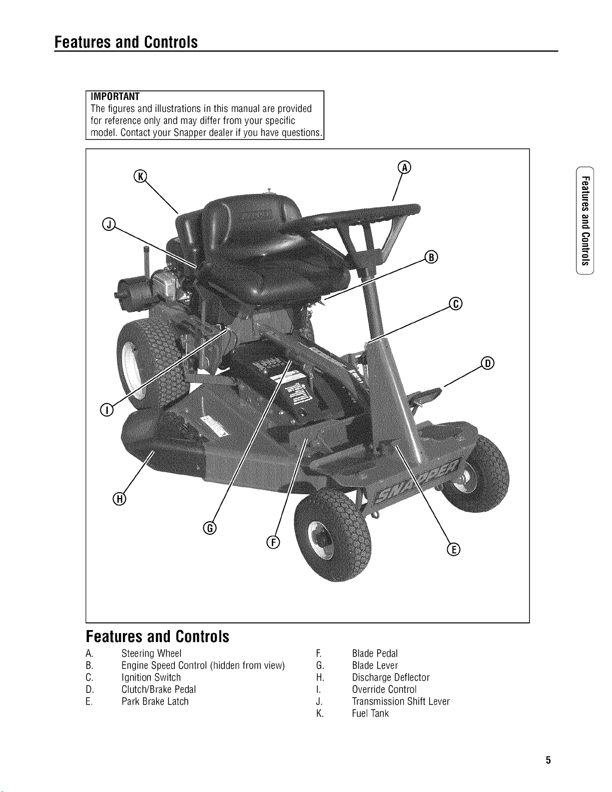
FeaturesandControls
A. Steering Wheel F.
B. EngineSpeedControl (hidden from view) G.
C. Ignition Switch H.
D. Clutch/Brake Pedal I.
E. Park BrakeLatch J.
K.
Blade Pedal
Blade Lever
DischargeDeflector
OverrideControl
TransmissionShift Lever
FuelTank
,m
Operation
Pre-StartCheckList
Make the following checks and perform the service required
before eachstart-up:
1. Checkthe tire pressure; add or releaseair as neededto
bring pressureto 12 PSI in front and 12 PSI in rear.
2. Checkguards, deflectors and coversto make sure all are
in placeand securelytightened.
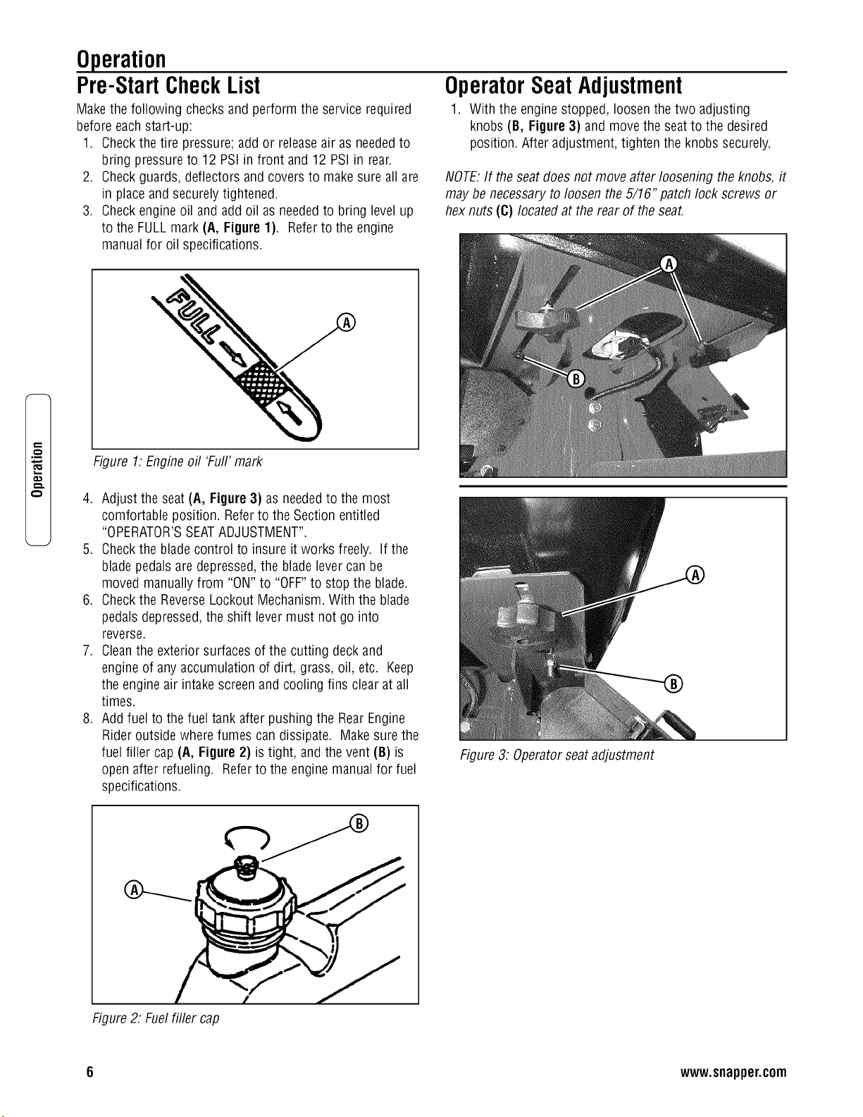
3. Checkengineoil and add oil as neededto bring levelup
to the FULLmark (A, Figure1). Referto the engine
manualfor oil specifications.
OperatorSeatAdjustment
1. With the enginestopped, loosenthe two adjusting
knobs (B, Figure3) and move the seatto the desired
position. After adjustment, tighten the knobs securely.
NOTE:If the seat does not move after loosening the knobs, it
may be necessary to loosen the 5/16" patch lock screws or
hex nuts (C) located at the rear of the seat.
Figure 1:Engine oil 'Full' mark
4. Adjustthe seat(A, Figure 3) as neededto the most
comfortable position. Referto the Section entitled
"OPERATOR'SSEATADJUSTMENT".
5. Checkthe blade control to insure it works freely. Ifthe
blade pedalsare depressed,the blade levercan be
moved manuallyfrom "ON" to "OFF"to stop the blade.
6. Checkthe ReverseLockout Mechanism.With the blade
pedalsdepressed,the shift lever must not go into
reverse.
7. Cleanthe exterior surfaces of the cutting deck and
engine of any accumulation of dirt, grass, oil, etc. Keep
the engine air intake screenand cooling fins clear at all
times.
8. Addfuel to the fuel tank after pushing the RearEngine
Rider outside where fumes can dissipate. Make surethe
fuel filler cap (A, Figure2) is tight, and the vent (B) is
open after refueling. Referto the engine manual for fuel
specifications.
Figure3: Operatorseatadjustment
Figure2: Fuelfiller cap
6 www.snapper.com
Operation(Continued)
Starting and Operation
Engine (Electric Start)
.
After the enginestarts, move the engine speedcontrol
to the "FAST"position and allow a brief warm-up until
engine runs smooth.
IMPORTANT:Whenthe ignition key is turned to "START",the
engine will turn over, but will not start unless the
Clutch/Brakepedal is pressed all the way down, and the
Blade Leveris in the "OFF"position. The operator should be
in the seat.
Start the engine asfollows:
1. Openthe vent (B, Figure 2) on the fuel filler cap (A) by
turning counterclockwise.
IMPORTANT:Failureto open the vent on the fuel filler cap
can causethe engine to stall.
2. Movethe transmission shift leverto the (N) Neutral
position. Referto the section entitled "Wheel Drive".
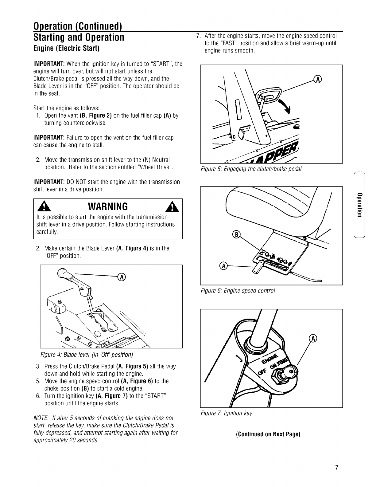
Figure 5. Engagingthe clutch/brake pedal
IMPORTANT:DONOTstart the enginewith thetransmission
shift lever in a drive position.
WARNING
It is possible to start the engine with the transmission
shift lever in a drive position. Follow starting instructions
carefully.
2. Makecertainthe BladeLever(A, Figure 4) is in the
"OFF"position.
mo
Figure 6: Enginespeedcontrol
Figure4: Bladelever (in 'Off' position)
3. Pressthe Clutch/BrakePedal(A, Figure 5) all the way
down and hold while starting the engine.
5. Movethe enginespeedcontrol (A, Figure 6) to the
choke position (B) to start a cold engine.
6. Turnthe ignition key (A, Figure 7) to the "START"
position until the engine starts.
NOTE: If after 5 seconds of cranking the engine doesnot
start, releasethe key,make sure the Clutch/BrakePedal is
fully depressed,and attempt starting again after waiting for
approximately 20 seconds.
Figure 7: Ignition key
(Continuedon NextPage)
.m
Operation(Continued)
StartingandOperation(Continued)
Engine (Electric Start) (Continued)
8. Shouldthe battery be too weak to start the engine, refer
to the Section entitled "Engine(ManualStart)" to
manually start the electric start engines.
9. OnModel 3317523BVEand C3317523BVE,the engine is
equipped with a fuel shut-off solenoid. If the battery is
dead,the engine can be startedwith the recoil back-up
starter if the engine speedcontrol is in the choke
position (HOTengine or COLDengine).
Engine(Manual Start)
IMPORTANT:Whenthe key is turned to "ON", and the recoil
handle is pulled, the engine will turn over, but will not start
unless the Clutch/BrakePedal is pressed all the way down
with the ParkBrakeengaged,and the BladeLever is in the
"Off" position.
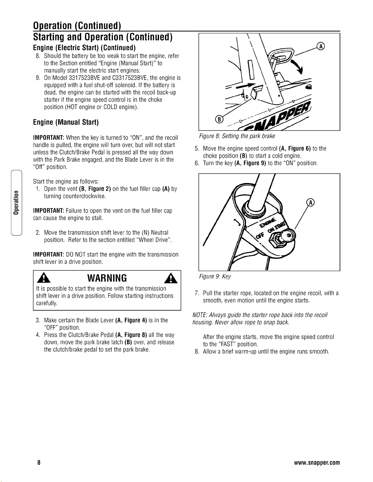
Figure 8: Setting thepark brake
5. Movethe enginespeedcontrol (A, Figure6) to the
choke position (B) to start a cold engine.
6. Turnthe key(A, Figure 9) to the "ON" position.
Start the engine asfollows:
1. Openthe vent (B, Figure 2) on the fuel filler cap (A) by
turning counterclockwise.
IMPORTANT:Failureto open the vent on the fuel filler cap
can causethe engine to stall.
2. Movethe transmission shift leverto the (N) Neutral
position. Referto the section entitled "Wheel Drive".
IMPORTANT:DONOTstart the enginewith thetransmission
shift lever in a drive position.
WARNING
It is possible to start the engine with the transmission
shift lever in a drive position. Follow starting instructions
carefully.
3. Makecertainthe BladeLever(A, Figure4) is in the
"OFF"position.
4. Pressthe Clutch/BrakePedal(A, Figure 8) all the way
down, move the park brake latch (B) over, and release
the clutch/brake pedalto set the park brake.
Figure 9: Key
7. Pullthe starter rope,located on the engine recoil, with a
smooth, even motion until the engine starts.
NOTE:Always guide the starter rope back into the recoil
housing. Never allow rope to snap back.
After the enginestarts, move the engine speedcontrol
to the "FAST"position.
8. Allow a brief warm-up until the engine runs smooth.
8 www.snapper.com
Operation(Continued)
WARNING
Onceblade is disengaged,it should come to a complete
stop in 3 secondsor less. If the blade continues to rotate
after 3 seconds, the blade brake must be adjusted. Refer to
Section "BLADE BRAKEADJUSTMENT"for adjustment pro-
cedures or return machineto an authorized SNAPPERdeal-
er for adjustment. DONOTCONTINUEto operate machine
until blade brakeis adjusted and functioning properly.
StartingandOperation(Continued)
Mower Blade
1. With the enginerunning, move the engine speedcontrol
to the "FAST"position.
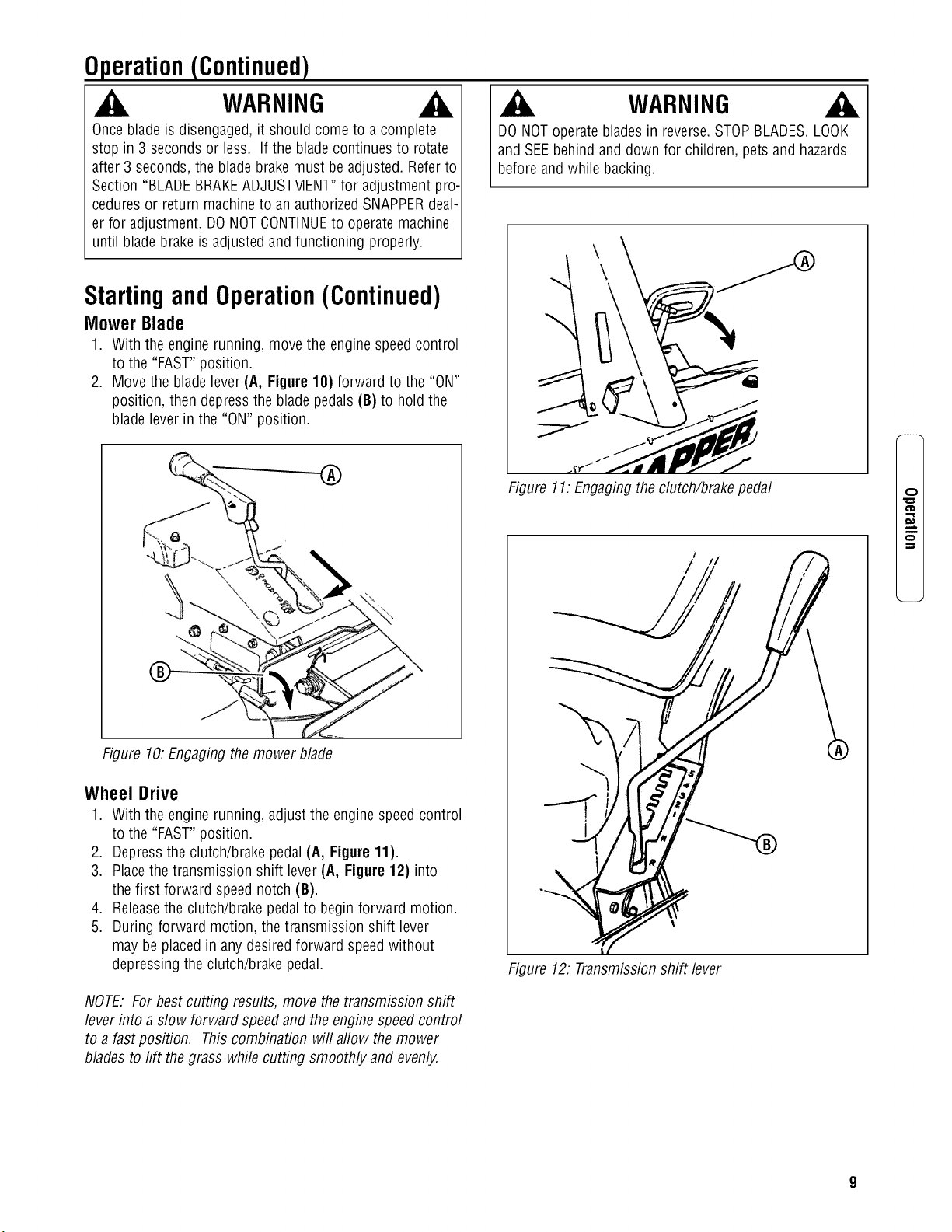
2. Movethe bladelever (A, Figure 18) forward to the "ON"
position, then depressthe blade pedals(B) to hold the
blade lever in the "ON" position.
1
Figure 10.Engaging themower blade
Wheel Drive
1. With the enginerunning, adjust the engine speedcontrol
to the "FAST"position.
2. Depressthe clutch/brake pedal (A, Figure 11).
3. Placethetransmission shift lever(A, Figure 12) into
the first forward speednotch (B).
4. Releasethe clutch/brake pedalto begin forward motion.
5. During forward motion, the transmission shift lever
may be placedin anydesired forward speedwithout
depressing the clutch/brake pedal.
NOTE. For best cutting results, move the transmission shift
lever into a slow forward speedand the enginespeed control
to a fast position. Thiscombination will allow themower
blades to lift thegrass whilecutting smoothly and evenly.
WARNING
DONOToperateblades in reverse.STOPBLADES.LOOK
and SEEbehind and down for children, pets and hazards
before and while backing.
Figure 11.Engagingthe clutch/brake pedal
//
I
Figure 12: Transmissionshift lever
m.
Operation(Continued)
,_ WARNING _k 1
DONOTleavethe machine with the engine running. STOP I
Blade.STOPengine.Shift to neutral and engagepark brake.I
Removekey. J
Mower Blade
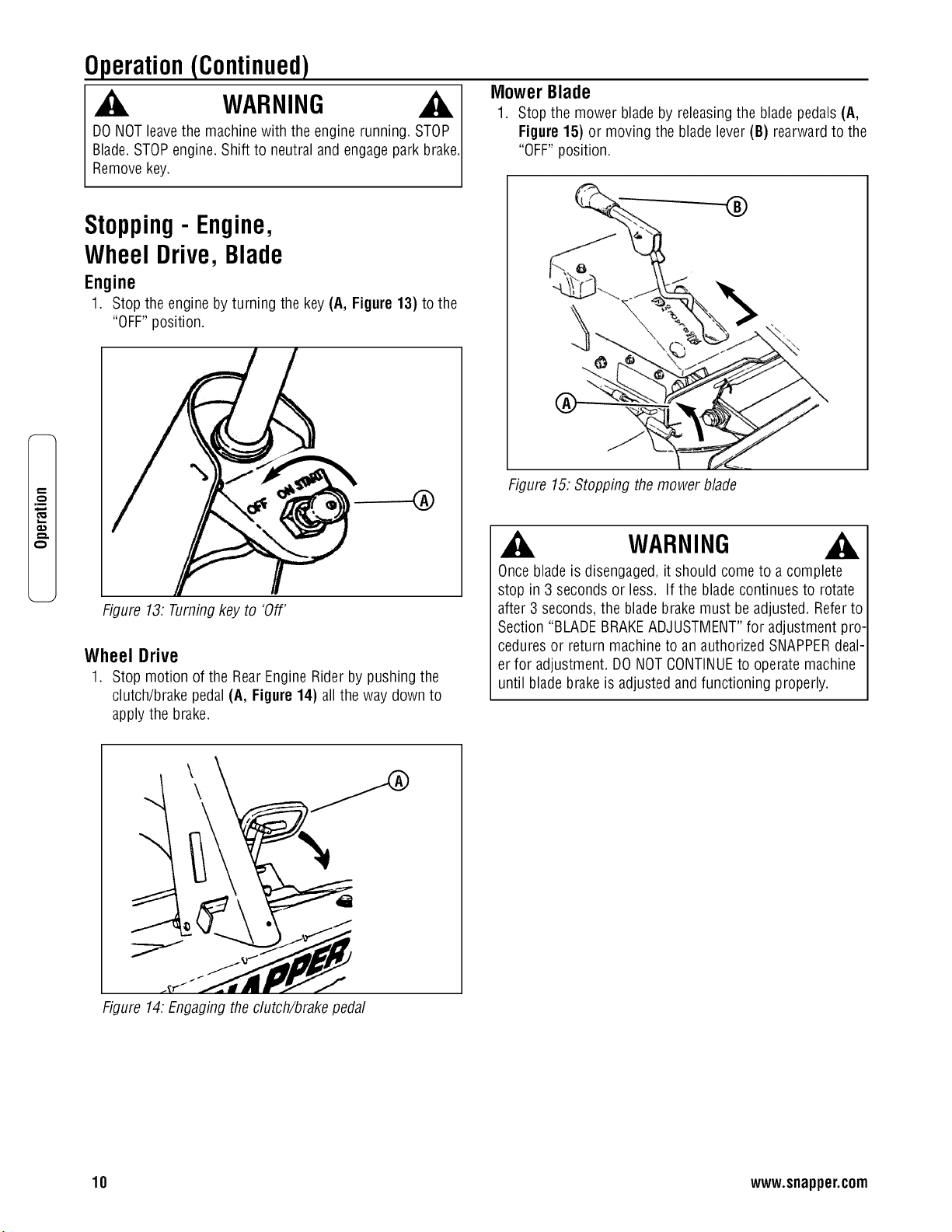
1. Stop the mower bladeby releasingthe bladepedals(A,
Figure 15) or moving the blade lever (B) rearwardto the
"OFF"position.
q..
.m
e-,
Stopping- Engine,
WheelDrive,Blade
Engine
1. Stop the engineby turning the key (A, Figure13) to the
"OFF"position.
Figure 13. Turningkey to 'Off'
Wheel Drive
1. Stop motion of the RearEngine Rider by pushing the
clutch/brake pedal (A, Figure14) all the way down to
apply the brake.
Figure 15.Stopping themower blade
WARNING
Onceblade is disengaged,it should come to a complete
stop in 3 secondsor less. If the blade continues to rotate
after 3 seconds, the bladebrake must be adjusted. Referto
Section "BLADEBRAKEADJUSTMENT"for adjustment pro-
cedures or return machineto an authorized SNAPPERdeal-
er for adjustment. DONOTCONTINUEto operatemachine
until blade brakeis adjusted andfunctioning properly.
Figure 14.Engaging theclutch/brake pedal
10 www.snapper.com
Operation(Continued)
Stopping- Engine, Wheel
Blade(Continued)
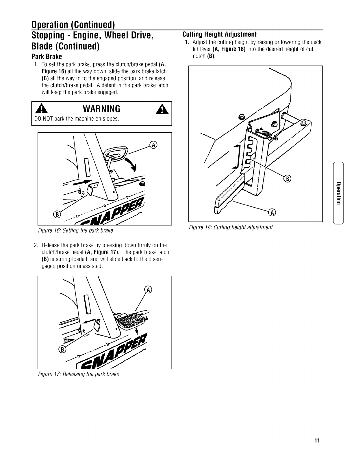
Park Brake
Drive,
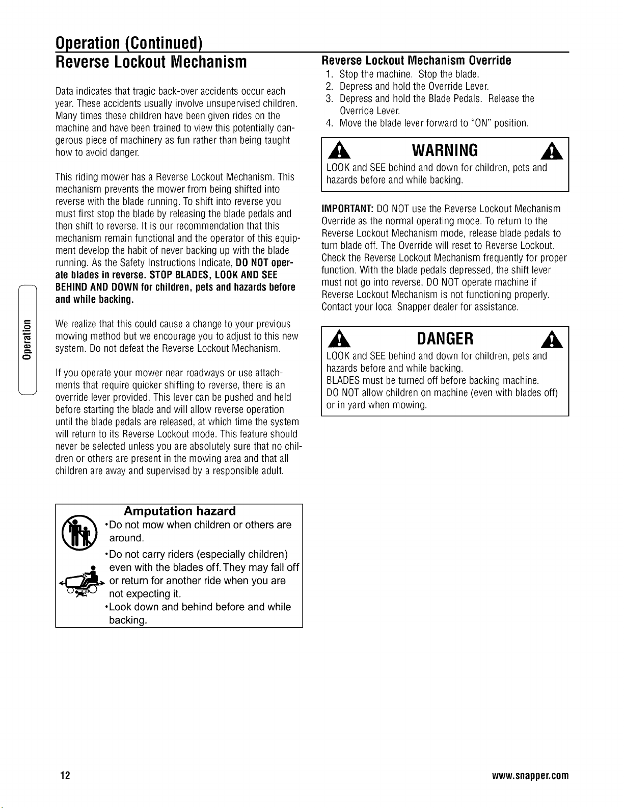
Cutting Height Adjustment
1. Adjustthe cutting height by raising or lowering the deck
lift lever(A, Figure 18) into the desired height of cut
notch (B).
.
Toset the park brake, pressthe clutch/brake pedal (A,
Figure 16) all the way down, slide the park brakelatch
(B) all the way in to the engaged position, and release
the clutch/brake pedal. A detent in the park brakelatch
will keepthe park brakeengaged.
_i_ WARNING
DONOTpark the machine on slopes.
A
Figure 16.Setting thepark brake
I
/
Figure 18.Cutting height adjustment
.
Releasethe park brake by pressmgdown firmly on the
clutch/brake pedal (A, Figure 17). Thepark brake latch
(B) is spring-loaded, and will slide back to the disen-
gaged position unassisted.
¢D
m.
Figure 17.Releasingthe park brake
11
.m
Operation(Continued)
ReverseLockoutMechanism
Data indicatesthat tragic back-over accidentsoccur each
year.Theseaccidents usually involve unsupervised children.
Many times these children havebeen given rides on the
machine and havebeentrained to view this potentially dan-
gerous pieceof machinery asfun rather than being taught
how to avoid danger.
This riding mower hasa ReverseLockout Mechanism.This
mechanism preventsthe mower from being shifted into
reversewith the blade running. To shift into reverseyou
must first stop the blade by releasingthe bladepedalsand
then shift to reverse.It is our recommendationthat this
mechanism remainfunctional and the operator of this equip-
ment developthe habit of neverbacking up with the blade
running. Asthe SafetyInstructions Indicate, DONOToper-
ate bladesin reverse. STOPBLADES,LOOKANDSEE
BEHINDANDDOWNfor children, petsand hazardsbefore
and while backing.
ReverseLockout MechanismOverride
1. Stop the machine. Stop the blade.
2. Depressand hold the OverrideLever.
3. Depressand hold the Blade Pedals. Releasethe
Override Lever.
4. Movethe bladelever forward to "ON" position.
WARNING
LOOKand SEEbehind and down for children, pets and
hazards beforeand while backing.
IMPORTANT:DONOTusethe ReverseLockout Mechanism
Overrideasthe normal operating mode. To return to the
ReverseLockout Mechanism mode, releaseblade pedalsto
turn blade off. The Overridewill resetto ReverseLockout.
Checkthe ReverseLockout Mechanism frequently for proper
function. With the blade pedalsdepressed,the shift lever
must not go into reverse.DONOToperatemachine if
ReverseLockout Mechanism is not functioning properly.
Contactyour local Snapper dealerfor assistance.
We realizethat this could cause a changeto your previous
mowing method but weencourageyou to adjust to this new
system. Do not defeatthe ReverseLockout Mechanism.
If you operateyour mower near roadwaysor useattach-
ments that require quicker shifting to reverse,there is an
override lever provided. This levercan be pushed and held
before starting the bladeand will allow reverseoperation
until the blade pedalsare released,at which time the system
will returnto its ReverseLockout mode. This feature should
never beselected unlessyou are absolutely surethat no chil-
dren or others are present in the mowing areaand that all
children are away and supervised by a responsible adult.
DANGER
LOOKand SEEbehind and down for children, pets and
hazards beforeand while backing.
BLADESmust be turned off before backing machine.
DONOTallow children on machine (evenwith blades off)
or in yard when mowing.
Amputation hazard
.Do not mow when children or others are
around.
•Do not carry riders (especially children)
• even with the blades off.They may fall off
or return for another ride when you are
not expecting it.
•Look down and behind before and while
backing.
12 www.snapper.com
Maintenance
WARNING
DONOTattempt anyadjustments, maintenance,service or
repairswith the engine running. STOPengine.STOPblade.
Engageparking brake. Removekey.Removespark plug
wire from spark plug and secureaway from plug. Engine
and components are HOT.Avoid serious burns, allow all
parts to cool beforeworking on machine.FuelFillerCap
and vent must beclosed securelyto prevent fuel spillage.
Introduction
Toretain the quality of the RearEngineRider, usegenuine
SNAPPERreplacementparts only. Contact a localSNAPPER
dealerfor parts and service assistance. Forthe correct part
or information for a particular RearEngineRiding Mower,
always mention the model and serial number. SNAPPERrec-
ommends returning the RearEngine Riderto an authorized
SNAPPERdealer annuallyfor inspection and addition of any
new devices,which might upgrade the safety of the Rear
Engine Rider. Forthe nearestSNAPPERdealer in your area,
checkthe yellow pages underthe heading LAWNMOWERS.
For engine parts and service, look for the enginemanufactur-
er's dealersunder the heading, ENGINES- gasoline.
Service- AftertheFirst5 Hours
Routine maintenanceis important to the performance and
life of your RearEngineRider.Service performed properly
and at the recommendedinterval is essential. Referto the
section entitled "MAINTENANCESCHEDULE"in this manual
and in the Engine Owner'sManual. Carefullycomplete all of
the recommendedservice procedures.
ChangeEngineOil
1. Placebricks or wooden blocks under the front wheels to
lower the rear of the engine.
2. Loosen or removethe oil fill cap on the engine.
3. Placea 2 quart minimum capacity container under the
end of the oil drain (Figure 19).
4. Removeor open the oil drain plug (A or B, Figure 19),
depending upon the type of oil drain plug the engine is
equipped with.
/
/
/
Figure 19.Offdrain plugs
5. After all the oil hasdrained, replaceor close the drain
plug, and wipe up anyoil that may havespilled.
Disposeof used oil properly.
6. Fill the engine crankcasewith new oil. Referto the
engine manualfor oil specifications.
7. Changethe oil filter on enginesequipped with oil filters
at every oil change. Referto the engine manualfor serv-
ice instructions.
ServiceEngineAir Cleaner
Theengine is equipped with a dual element air cleaner.Both
the foam pre-cleanerand cartridge require service. Referto
the Engine Manualfor recommendedservice procedures.
CheckMowerBlade
1. Followthe WARNINGstatementfound on this page.
2. Checkthe fuel level in the tank. If over 3/4 full, remove
the tank. Referto the section entitled "REMOVINGFUEL
TANK".If 3/4 or less, proceedto the next step.
3. Carefullystand the RearEngine Rideron the rear
bumper.
DANGER
Removethe battery if the RearEngine Riderwill be left
standing on the rear bumper for longer than 2 hours. Refer
to the section entitled "BATTERYREMOVAL".DONOTuse
a cutting blade that shows signs of excessivewearor
damageon the RearEngineRider. Referto the section
entitled "MOWERBLADEREPLACEMENT"for proper
blade inspection and service procedures.
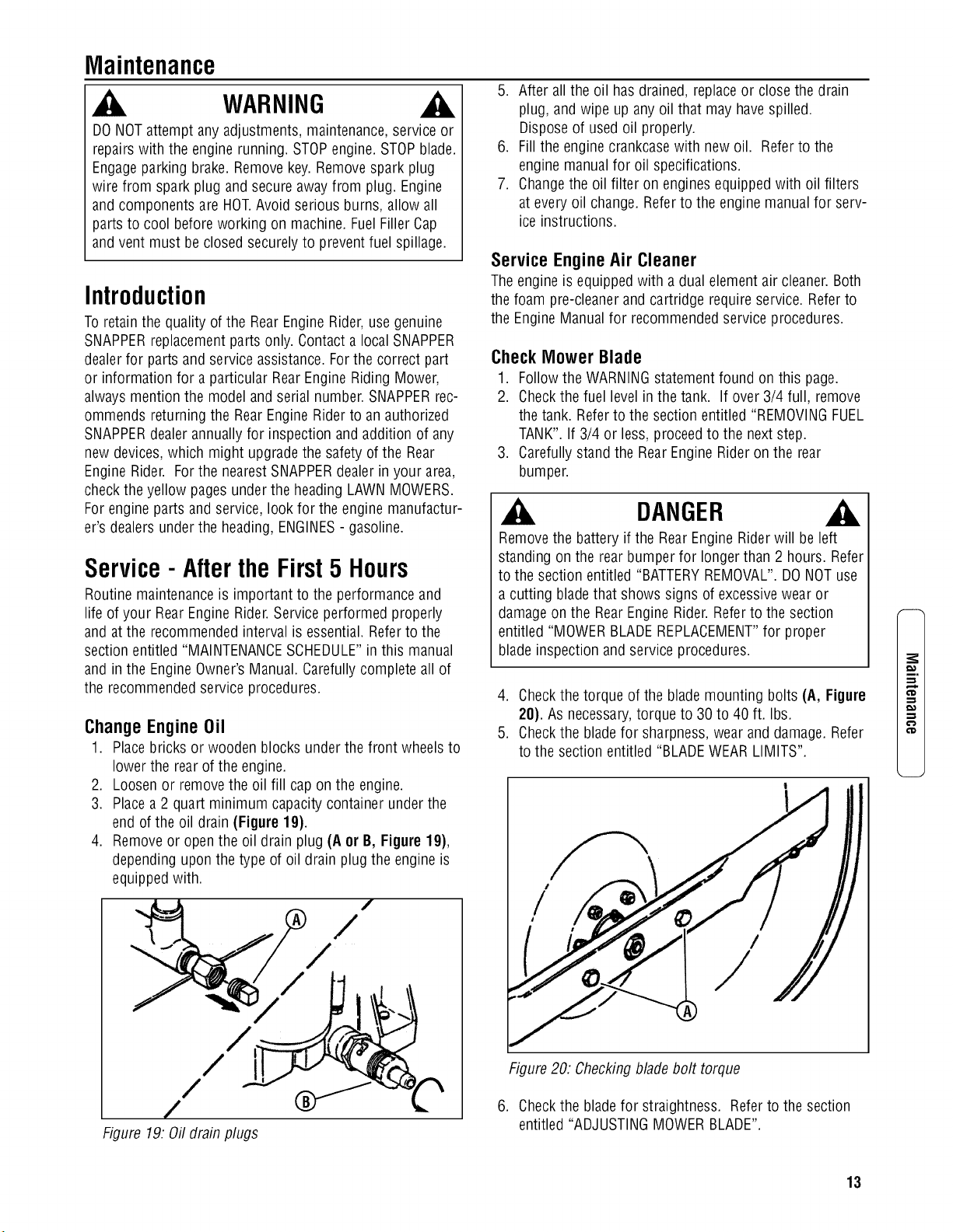
4. Checkthe torque of the blademounting bolts (A, Figure
20). As necessary,torque to 30 to 40 ft. Ibs.
5. Checkthe bladefor sharpness, wear and damage. Refer
to the section entitled "BLADEWEARLIMITS".
/
/
Figure20. Checkingblade bolt torque
6. Checkthe bladefor straightness. Referto the section
entitled "ADJUSTINGMOWERBLADE".
m.
13
Maintenance(Continued)
WARNING
DONOTattempt anyadjustments, maintenance,service or
repairswith the engine running. STOPengine.STOPblade.
Engageparking brake. Removekey.Removespark plug
wire from spark plug and secureaway from plug. Engine
and components are HOT.Avoid serious burns, allow all
parts to cool beforeworking on machine.FuelFillerCap
and vent must beclosed securelyto prevent fuel spillage.
.m
Service- AftertheFirst5 Hours
(Continued)
Check the Blade Drive Belt
The bladedrive consists of a single beltfrom the engine to
the deck. Inspect for signs of deterioration and proper ten-
sion.
1. Lower the deckto the lowest setting.
2. Removethe four self-tapping screws (A, Figure 21),
two on eachside of mower drive belt cover (B).
3. Slidethe cover backandrotateout on the left sideof
the mower deck.
Figure21. Removing the drive belt cover
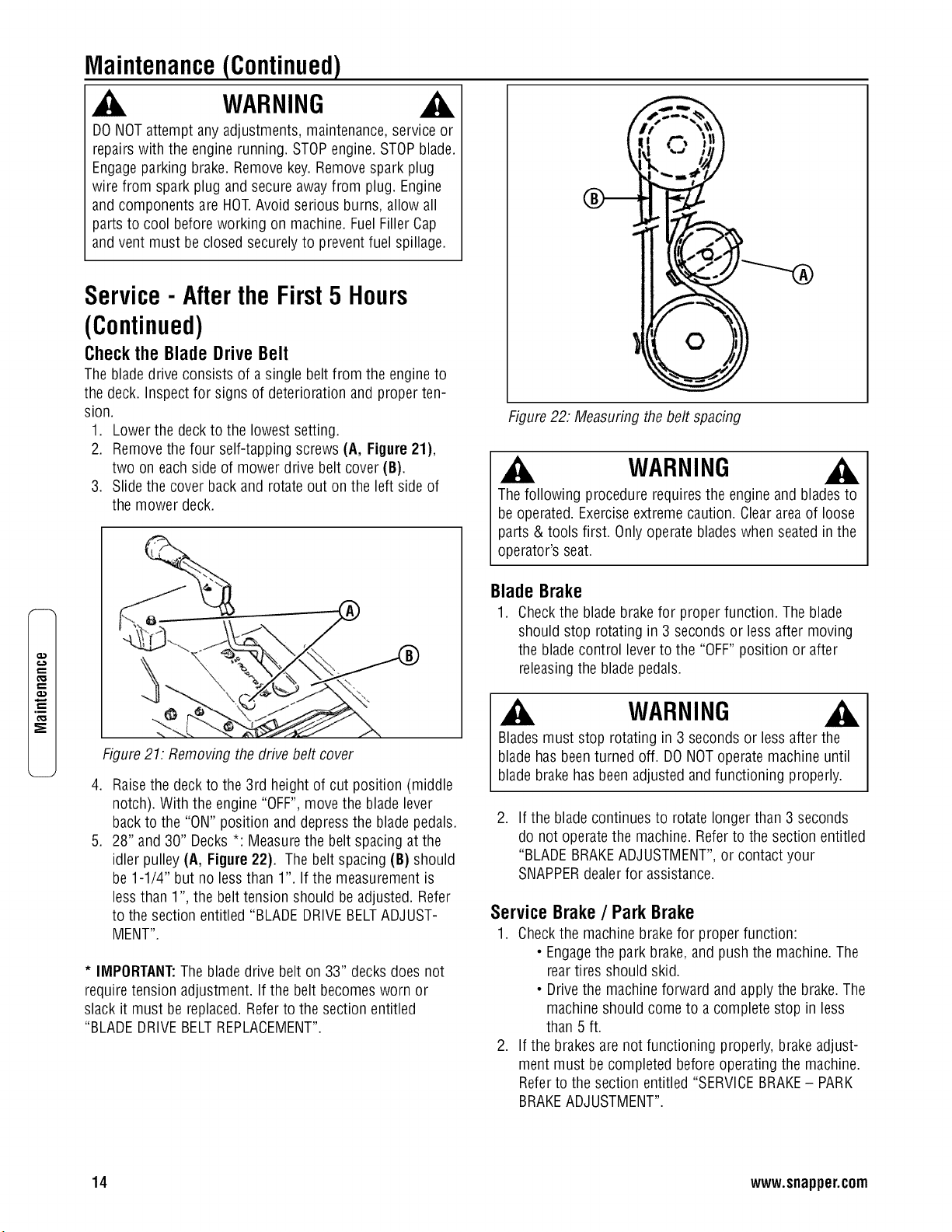
.
.
Raisethe deck to the 3rd height of cut position (middle
notch). With the engine "OFF",move the blade lever
back to the "ON" position and depressthe bladepedals.
28" and 30" Decks *: Measurethe belt spacing at the
idler pulley (A, Figure22). The beltspacing (B) should
be 1-1/4" but noless than 1". If the measurement is
less than 1", the belttension should be adjusted. Refer
to the section entitled "BLADE DRIVEBELTADJUST-
MENT".
* IMPORTANT:Theblade drive belt on 33" decksdoes not
require tension adjustment. If the belt becomesworn or
slack it must be replaced.Refer to the section entitled
"BLADEDRIVEBELTREPLACEMENT".
Figure22. Measuring thebelt spacing
WARNING
Thefollowing procedure requiresthe engine and bladesto
be operated. Exerciseextreme caution. Cleararea of loose
parts & tools first. Only operatebladeswhen seatedin the
operator's seat.
Blade Brake
1. Checkthe blade brakefor proper function. Theblade
should stop rotating in 3 seconds or less after moving
the blade control lever to the "OFF"position or after
releasingthe blade pedals.
WARNING
Bladesmust stop rotating in 3 secondsor less after the
blade has beenturned off. DONOToperatemachine until
blade brakehas been adjusted andfunctioning properly.
.
If the blade continues to rotate longer than 3 seconds
do not operatethe machine.Refer to the section entitled
"BLADEBRAKEADJUSTMENT",or contact your
SNAPPERdealer for assistance.
ServiceBrake/ ParkBrake
1. Checkthe machine brakefor proper function:
• Engagethe park brake,and push the machine.The
reartires should skid.
• Drivethe machineforward and applythe brake.The
machine should come to a complete stop in less
than 5 ft.
2. If the brakes are not functioning properly, brake adjust-
ment must becompleted beforeoperating the machine.
Referto the section entitled "SERVICEBRAKE- PARK
BRAKEADJUSTMENT".
14 www.snapper.com
Maintenance(Continued)
Service - After the First5 Hours
(Continued)
Safety Interlock System Checks
Perform the following interlock system checksperiodically
during the operating season.Contact your authorized
Snapper dealerif you havequestions.
WARNING
DONOToperatemachine if anysafety interlock or safety
device is not in placeand functioning properly. DONOT
attempt to defeat, modify or removeany safety device.
Engine must not start if:
1. TheClutch/BrakePedal is not fully depressedOR,
2. The BladeControl is in the "ON" (bladesengaged) posi-
tion.
Engine should start if:
1. The BladeControl is in the "OFF"(blades disengaged)
position AND,
2. TheClutch/BrakePedal isfully depressed.
Engine and bladesmust stop if:
1. Theoperator rises off of seatwith BladeControl in "ON"
(blades engaged)position OR,
2. Theoperator rises off of seatwith Clutch/BrakePedal
not fully depressed.
Reverse Lockout Mechanism
Checkthe function of the ReverseLockout Mechanism with
the engine off.
1. Depressand hold the blade pedals.
2. Depressand hold the clutch/brake pedal.
3. With Steps1 and 2 performed, the shift lever must not
go into reverse.
WARNING
0 NOToperatemachine if ReverseLockout Mechanism is
ot functioning properly. Contactyour SNAPPERdealer
mmediately for assistance.
Lubrication - GreaseFittings
Thefollowing components on the RearEngineRider are
equipped with greasefittings and require periodic lubrica-
tion. Apply GeneralPurpose grease(NLGINo.2) with a
greasegun.
1. FrontWheel Bearings.Referto the section entitled
"FRONTWHEELBEARINGS- LUBRICATION".
2. RearAxle Bearing.Referto the section entitled "REAR
AXLEBEARING- LUBRICATION".
3. Mower BladeSpindle. Referto the section entitled
"MOWER BLADESPINDLE- LUBRICATION".
4. Shift Lever.Referto the section entitled "SHIFTLEVER-
LUBRICATION".
Service- Every25 OperatingHours
Perform all service required after the first 5 hours of opera-
tion. Referto the section entitled "SERVICE- AFTER5
HOURS".
CheckEngine
1. Changethe engine oil. Referto the section entitled
"CHANGEENGINEOIL". Referto the engine manualfor
oil specifications.
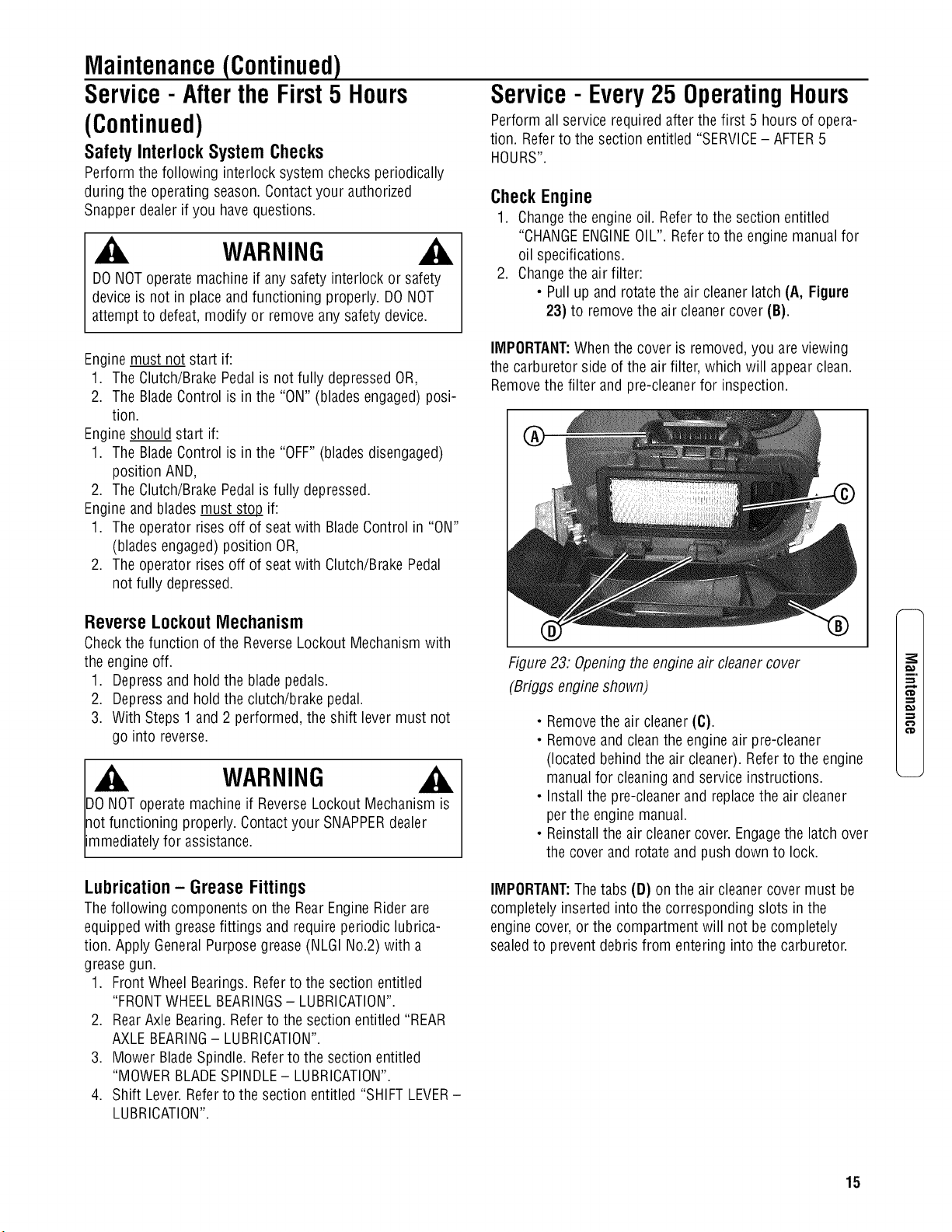
2. Changethe air filter:
• Pull up and rotate the air cleanerlatch (A, Figure
23) to removethe air cleanercover (B).
IMPORTANT:Whenthe cover is removed,you are viewing
the carburetor side of the air filter, which will appear clean.
Removethe filter and pre-cleanerfor inspection.
®
Figure23: Opening theengine air cleanercover
(Briggs engine shown)
• Removethe air cleaner(C).
• Removeand cleanthe engine air pre-cleaner
(located behindthe air cleaner). Referto the engine
manualfor cleaning and service instructions.
• Installthe pre-cleanerand replacethe air cleaner
per the engine manual.
• Reinstallthe air cleanercover. Engagethe latch over
the cover and rotate and push down to lock.
IMPORTANT:Thetabs (D) on the air cleanercover must be
completely inserted into the corresponding slots in the
engine cover,or the compartment will not be completely
sealedto preventdebris from entering into the carburetor.
m,
¢D
,-1
o,}
,-1
15
,m
Maintenance(Continued)
WARNING
DONOTattempt anyadjustments, maintenance,service or
repairswith the engine running. STOPengine.STOPblade.
Engageparking brake. Removekey.Removespark plug
wire from spark plug and secureaway from plug. Engine
and components are HOT.Avoid serious burns, allow all
parts to cool beforeworking on machine.FuelFillerCap
and vent must beclosed securelyto prevent fuel spillage.
Service- Every25 OperatingHours
(Continued)
Battery Fluid Level
1. Removethe battery. Referto the section entitled
"BATTERYREMOVAL".
2. Removethe battery caps. Checkthe fluid level.
3. Addwater only to bring fluid to proper level. DONOT
OVERFILL.
4. Reinstallthe battery. Referto the section entitled
"BATTERYINSTALLATION".
MowerDeckLevelness
Checkthe mower deckfor proper level. Adjust as required.
Refer to the section entitled "MOWERDECKADJUSTMENT-
LEVELNESS".
CleanMower Deck
1. Followthe WARNINGstatementfound on this page.
2. Checkthe fuel levelin the tank. If over 3/4 full, remove
the tank. Referto the section entitled "REMOVINGFUEL
TANK". If 3/4 or less, proceedto the next step.
3. Carefullystand the RearEngineRider on the rear
bumper.
4. Cleanthe undersideof the mower deck, removing all
accumulation of grass clippings and debris.
5. Cleanthe top of the deck, removing all grass clippings
and debris.
Mower Blade Spindle - Lubrication
1. Followthe WARNINGstatementfound on this page.
2. Checkthe fuel levelin tank. If over 3/4 full, removethe
tank. Referto the section entitled "FUELTANK
REMOVAL".If 3/4 or less, proceedto the next step.
3. Carefullystand the RearEngineRider on the rear
bumper.
4. Lubricate the spindle greasefitting (A, Figure24) with
three shots of general purposegreasefrom a grease
gun.
IMPORTANT:If the RearEngine Riderwill be on its rear
bumper for longer than two hours, removethe battery. Refer
to the section entitled "BATTERYREMOVAL".
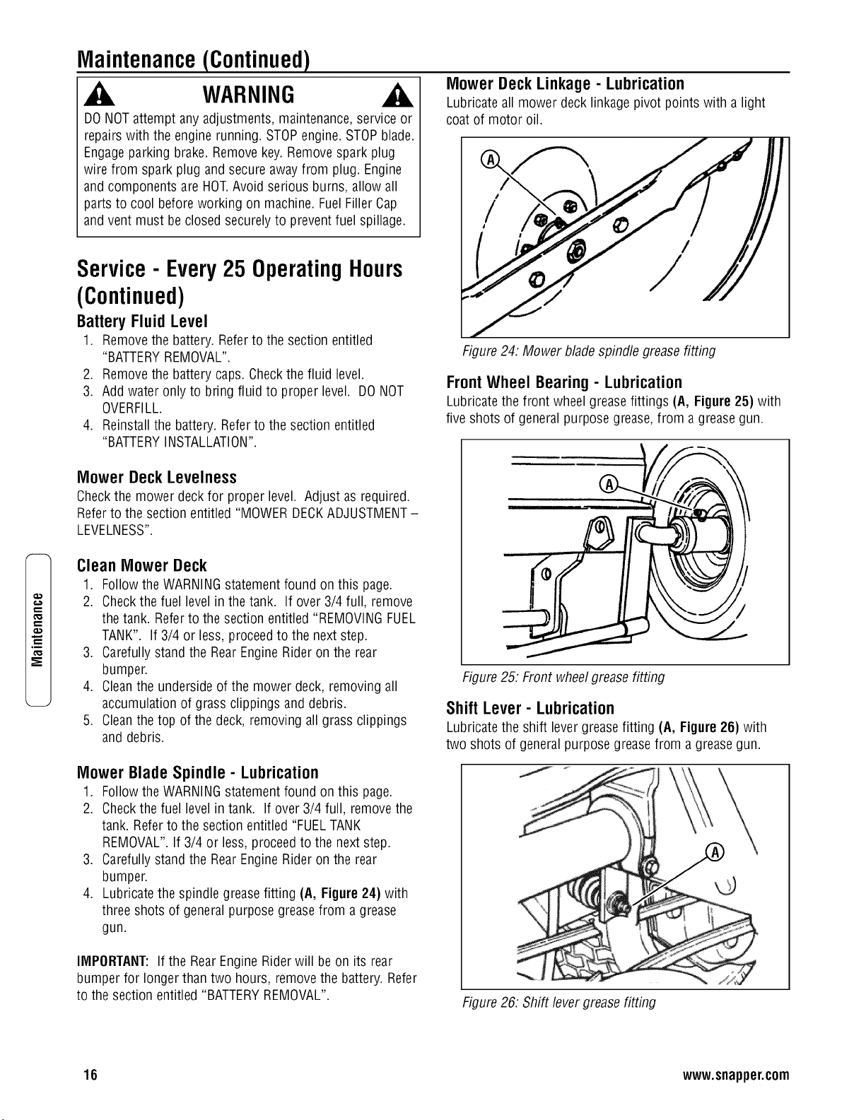
Mower Deck Linkage - Lubrication
Lubricateall mower deck linkage pivot points with a light
coat of motor oil.
®
/
Figure24. Mower blade spindle greasefitting
FrontWheel Bearing - Lubrication
Lubricatethe front wheelgreasefittings (A, Figure 25) with
five shots of general purpose grease,from a greasegun.
Figure25: Front wheelgrease fitting
Shift Lever - Lubrication
Lubricatethe shift levergreasefitting (A, Figure 26) with
two shots of general purpose greasefrom a greasegun.
Figure26: Shift levergrease fitting
16 www.snapper.com
Maintenance(Continued)
WARNING
DONOTattempt anyadjustments, maintenance,service or
repairswith the engine running. STOPengine.STOPblade.
Engageparking brake. Removekey.Removespark plug
wire from spark plug and secureaway from plug. Engine
and components are HOT.Avoid serious burns, allow all
parts to cool beforeworking on machine.FuelFillerCap
and vent must beclosed securelyto prevent fuel spillage.
.
Tocheck lubricant, removethe fill/level plug and visually
inspect for lubricant on the internal parts of the
differential. If no lubricant is visible on the internal parts
of the differential, add transmission greaseas needed.
IMPORTANT:Overfilling of the differential with lubricant will
cause lubricant to leakonto drive components of the Rear
Engine Rider.
Service- Every25 OperatingHours
(Continued)
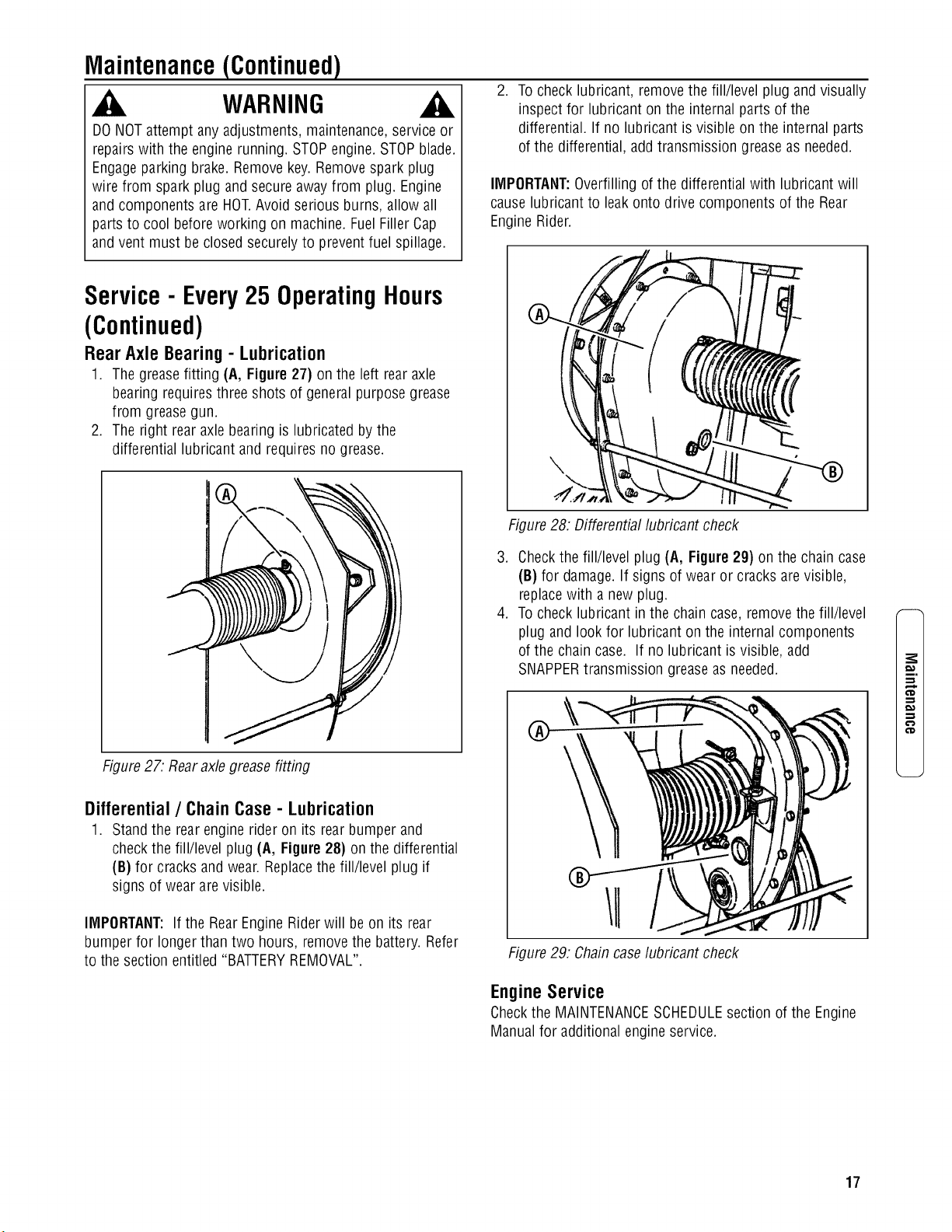
Rear Axle Bearing - Lubrication
1. Thegreasefitting (A, Figure27) on the left rearaxle
bearing requiresthree shots of general purposegrease
from greasegun.
2. The right rear axlebearing is lubricated by the
differential lubricant and requires no grease.
Figure27. Rearaxlegreasefitting
Differential/ ChainCase- Lubrication
1. Standthe rear engine rider on its rear bumper and
checkthe fill/level plug (A, Figure 28) on the differential
(B) for cracks and wear. Replacethe fill/level plug if
signs of wear are visible.
IMPORTANT:If the RearEngine Riderwill be on its rear
bumper for longer than two hours, removethe battery. Refer
to the section entitled "BATTERYREMOVAL".
Figure28. Differential lubricant check
3. Checkthe fill/level plug (A, Figure 29) on the chain case
(B) for damage.If signs of wearor cracks arevisible,
replacewith a new plug.
4. Tocheck lubricant in the chaincase, removethe fill/level
plug and look for lubricant on the internal components
of the chaincase. If no lubricant isvisible, add
SNAPPERtransmission greaseas needed.
®
\
Figure29. Chaincaselubricant check
EngineService
Checkthe MAINTENANCESCHEDULEsection of the Engine
Manualfor additional engineservice.
m.
€'D
17
.m
Maintenance(Continued)
WARNING
DONOTattempt anyadjustments, maintenance,service or
repairswith the engine running. STOPengine.STOPblade.
Engageparking brake. Removekey.Removespark plug
wire from spark plug and secureaway from plug. Engine
and components are HOT.Avoid serious burns, allow all
parts to cool beforeworking on machine.FuelFillerCap
and vent must beclosed securelyto prevent fuel spillage.
1. All bushingsand pivot areas.
2. Checkboth front wheelking pins.
3. Transmissionshift lever and detent.
4. Clutch disc.
5. Clutchyoke.
6. Mower deck linkageand pivot areas.
Replaceworn or damagedparts with genuine SNAPPER
replacementparts availablefrom an authorized SNAPPER
dealer.
Service- Annually
Engine
Perform all maintenanceasspecified in "MAINTENANCE
SCHEDULE"Section of this manual.
Storage(Outof Season)
If desired, the RearEngineRider can bestored on the rear
bumper. Perform the following proce
duresto insurethe RearEngine Riderwill operate properly
whentaken out of storage.
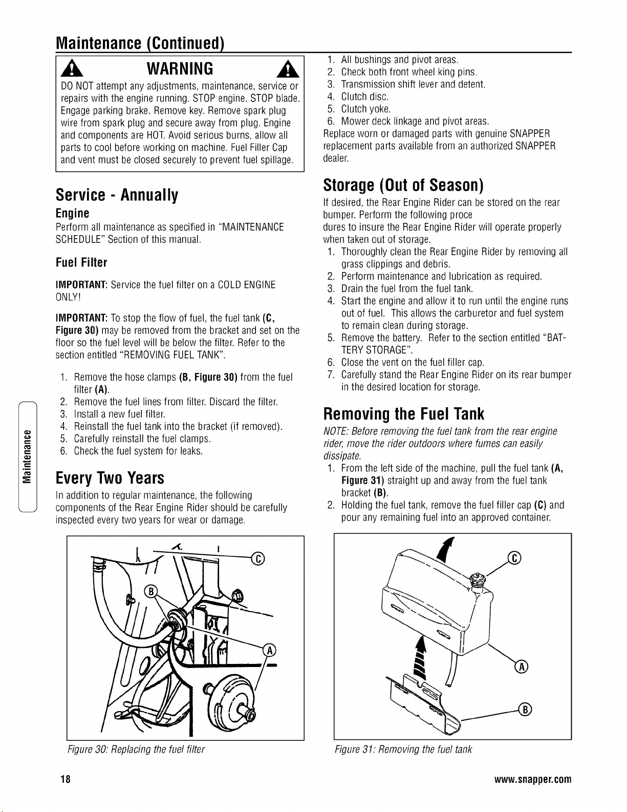
Fuel Filter
IMPORTANT:Service the fuel filter on a COLDENGINE
ONLY!
IMPORTANT:Tostop the flow of fuel, the fuel tank (C,
Figure 38) may be removed from the bracket and set on the
floor so the fuel levelwill bebelow the filter. Referto the
section entitled "REMOVINGFUELTANK".
1. Removethe hose clamps (B, Figure30) from the fuel
filter (A).
2. Removethe fuel lines from filter. Discardthe filter.
1. Thoroughly cleanthe RearEngine Riderby removing all
grass clippings and debris.
2. Perform maintenanceand lubrication as required.
3. Drainthe fuel from the fuel tank.
4. Start the engineand allow it to run until the engine runs
out of fuel. This allows the carburetor and fuel system
to remainclean during storage.
5. Removethe battery. Referto the section entitled "BAT-
TERYSTORAGE".
6. Closethe vent on the fuel filler cap.
7. Carefullystand the RearEngine Rideron its rear bumper
in the desired location for storage.
3. Install a newfuel filter.
4. Reinstallthe fuel tank into the bracket (if removed).
5. Carefully reinstallthe fuel clamps.
6. Checkthe fuel system for leaks.
EveryTwoYears
In additionto regular maintenance,the following
components of the RearEngine Ridershould be carefully
inspected everytwo years for wear or damage.
Removingthe FuelTank
NOTE:Beforeremoving the fuel tank from the rear engine
rider,move the rider outdoors wherefumes caneasily
dissipate.
1. Fromthe left side of the machine,pull the fuel tank (A,
Figure 31) straight up and awayfrom the fuel tank
bracket (B).
2. Holding the fuel tank, removethe fuel filler cap(C) and
pour any remaining fuel into an approvedcontainer.
-'{ I
--@
Figure30: Replacing the fuel filter Figure 31: Removing the fuel tank
18 www.snapper.com
Maintenance(Continued)
WARNING
DONOTattempt anyadjustments, maintenance,service or
repairswith the engine running. STOPengine.STOPblade.
Engageparking brake. Removekey.Removespark plug
wire from spark plug and secureaway from plug. Engine
and components are HOT.Avoid serious burns, allow all
parts to cool beforeworking on machine.FuelFillerCap
and vent must beclosed securelyto prevent fuel spillage.
EngineAdjustmentsandRepair
Refer to the engine manual for those adjustments and/or
repairs that can be madeby the owner.
MowerDeckandComponent
Adjustments
Thefollowing mower deck and component adjustments and
repairs can be made bythe owner. However,if there is diffi-
culty in achievingthese adjustments and repairs, it is recom-
mendedthat these repairsbe made by an authorized SNAP-
PERdealer.
Blade Brake Adjustment
Theautomatic Blade Brakeshould stopthe bladeswithin 3
seconds anytime the bladesare disengagedby moving the
blade leverto the "OFF"position or by releasingthe Blade
Pedals. If the bladestake longer than 3 secondsto stop,
perform the following measurementand adjustment.
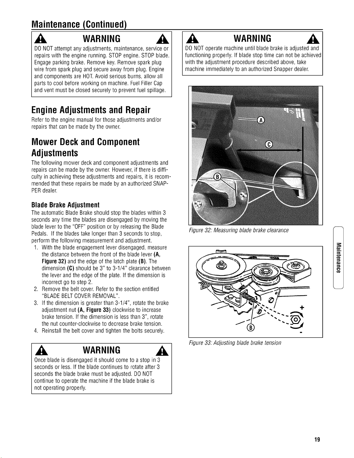
1. With the bladeengagementleverdisengaged, measure
the distance betweenthe front of the blade lever(A,
Figure32) and the edge of the latch plate (B). The
dimension (C) should be3" to 3-1/4" clearance between
the leverand the edgeof the plate. If the dimension is
incorrect go to step 2.
2. Removethe belt cover. Referto the section entitled
"BLADEBELTCOVERREMOVAL".
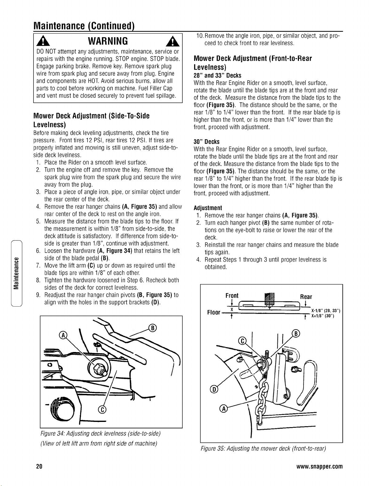
3. If the dimension is greaterthan 3-1/4", rotatethe brake
adjustment nut (A, Figure33) clockwise to increase
braketension. If the dimension is less than 3", rotate
the nut counter-clockwise to decreasebraketension.
4. Reinstallthe belt cover and tighten the bolts securely.
WARNING
Onceblade is disengagedit should come to a stop in 3
seconds or less. If the blade continuesto rotate after 3
secondsthe bladebrake must beadjusted. DONOT
continue to operatethe machine if the blade brakeis
not operating properly.
WARNING
DONOToperatemachine until blade brake is adjusted and
functioning properly. If blade stop time cannot be achieved
with the adjustment procedure described above,take
machine immediately to an authorized Snapper dealer.
Figure 32. Measuring blade brake clearance
Figure 33:Adjusting blade braketension
m,
19
,m
Maintenance(Continued)
WARNING
DONOTattempt anyadjustments, maintenance,service or
repairswith the engine running. STOPengine.STOPblade.
Engageparking brake. Removekey.Removespark plug
wire from spark plug and secureaway from plug. Engine
and components are HOT.Avoid serious burns, allow all
parts to cool beforeworking on machine.FuelFillerCap
and vent must beclosed securelyto prevent fuel spillage.
Mower Deck Adjustment (Side-To-Side
Levelness)
Before making deck leveling adjustments, checkthe tire
pressure. Fronttires 12 PSI, reartires 12 PSI. If tires are
properly inflated and mowing is still uneven,adjust side-to-
side deck levelness.
1. Placethe Rider on a smooth levelsurface.
2. Turnthe engine off and removethe key. Removethe
spark plug wire from the spark plug and secure thewire
away from the plug.
3. Placea pieceof angle iron, pipe,or similar object under
the rear center of the deck.
4. Removethe rear hanger chains (A, Figure 35) and allow
rear center of the deck to rest on the angle iron.
5. Measurethe distancefrom the bladetips to the floor. If
the measurement is within 1/8" from side-to-side, the
deck attitude is satisfactory. If differencefrom side-to-
side is greater than 1/8", continue with adjustment.
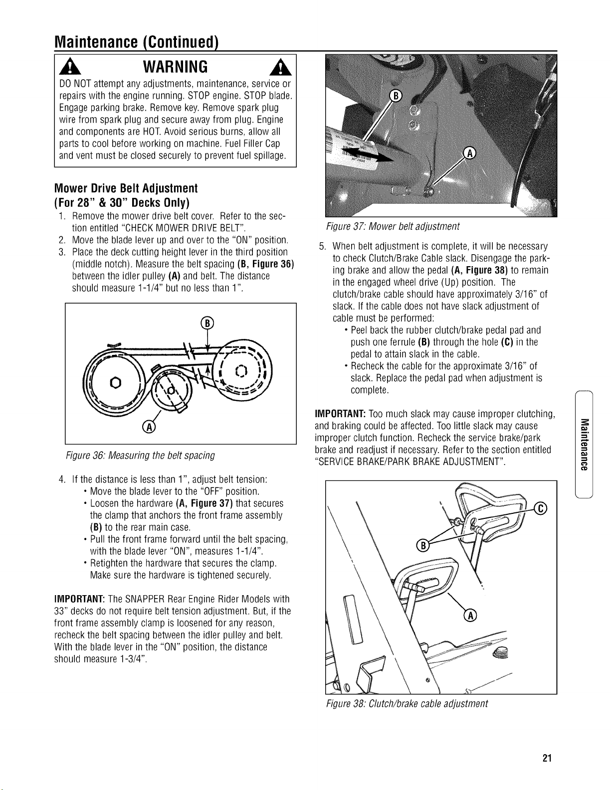
6. Loosenthe hardware(A, Figure 34) that retains the left
side of the bladepedal (B).
7. Movethe lift arm (C) up or down as required until the
blade tips are within 1/8" of eachother.
8. Tightenthe hardware loosenedin Step6. Recheckboth
sides of the deck for correct levelness.
9. Readjustthe rear hangerchain pivots (B, Figure35) to
align with the holes in the support brackets (D).
)
/
®
Figure34:Adjusting deck levelness(side-to-side)
(Viewof left rift arm from right side of machine)
lO.Remove the angle iron, pipe, or similar object, and pro-
ceedto checkfront to rear levelness.
Mower Deck Adjustment (Front-to-Rear
Levelness)
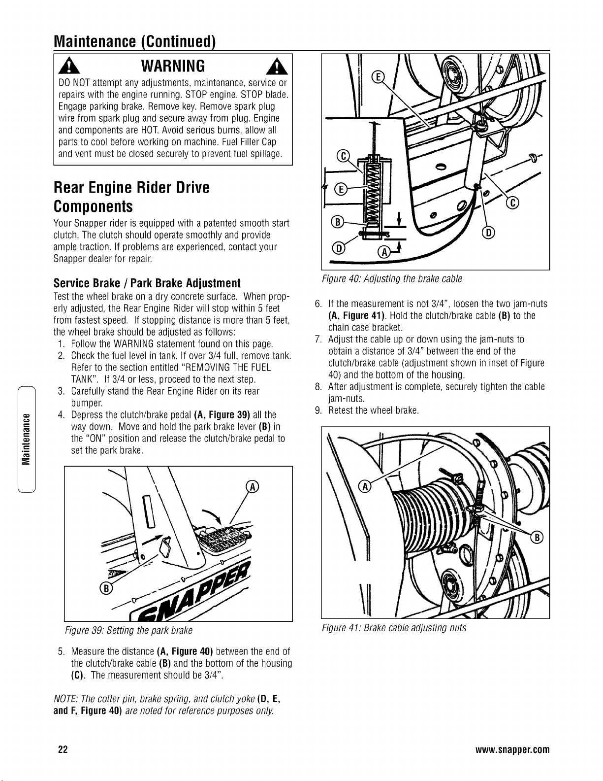
28" and 33" Decks
With the RearEngine Rideron a smooth, levelsurface,
rotatethe blade until the blade tips are at the front and rear
of the deck. Measurethe distance from the bladetips to the
floor (Figure35). The distanceshould bethe same,or the
rear 1/8" to 1/4" lower thanthe front. If the rear bladetip is
higher than the front, or is morethan 1/4" lower than the
front, proceedwith adjustment.
30" Decks
With the RearEngine Rideron a smooth, levelsurface,
rotatethe blade until the blade tips are at the front and rear
of the deck.Measurethe distancefrom the bladetips to the
floor (Figure 35). Thedistanceshould be the same,or the
rear 1/8" to 1/4" higher than the front. Ifthe rear bladetip is
lower than the front, or is more than 1/4" higher than the
front, proceedwith adjustment.
Adjustment
1. Removethe rear hangerchains (A, Figure 35).
2. Turneach hanger pivot (B) the same number of rota-
tions on the eye-boltto raise or lower the rear of the
deck.
3. Reinstallthe rear hanger chains and measurethe blade
tips again.
4. RepeatSteps 1 through 3 until proper levelnessis
obtained.
Front _ Rear
x_.L_[__---_ _
Floor ,
f f ×*1/8" (30")
Figure 35:Adjusting the mower deck (front-to-rear)
20 www.snapper.com
Maintenance(Continued)
WARNING
DONOTattempt anyadjustments, maintenance,service or
repairswith the engine running. STOPengine.STOPblade.
Engageparking brake. Removekey.Removespark plug
wire from spark plug and secureaway from plug. Engine
and components are HOT.Avoid serious burns, allow all
parts to cool beforeworking on machine.FuelFillerCap
and vent must beclosed securelyto prevent fuel spillage.
Mower Drive Belt Adjustment
(For28" & 30" DecksOnly)
1. Removethe mower drive belt cover. Referto the sec-
tion entitled "CHECKMOWERDRIVEBELT".
2. Movethe bladelever up and overto the "ON" position.
3. Placethe deck cutting height lever in the third position
(middle notch). Measurethe belt spacing (B, Figure 36)
betweenthe idler pulley(A) and belt. The distance
should measure1-1/4" but no less than 1"
Figure36. Measuring the belt spacing
.
If the distance is less than 1", adjust belt tension:
• Movethe bladeleverto the "OFF"position.
• Loosenthe hardware(A, Figure37) that secures
the clamp that anchors the front frame assembly
(B) to the rear main case.
• Pullthe front frame forward until the beltspacing,
with the bladelever"ON", measures1-1/4".
• Retightenthe hardwarethat securesthe clamp.
Make sure the hardwareis tightened securely.
IMPORTANT:TheSNAPPERRearEngineRider Models with
33" decksdo not require belt tension adjustment. But, if the
front frame assembly clamp is loosenedfor any reason,
recheckthe belt spacing betweenthe idler pulley and belt.
With the blade lever in the "ON" position, the distance
should measure1-3/4".
,
Figure 37: Mower belt adjustment
When belt adjustment is complete, it will benecessary
to check Clutch/BrakeCableslack. Disengagethe park-
ing brakeand allowthe pedal (A, Figure38) to remain
in the engagedwheel drive (Up) position. The
clutch/brake cableshould haveapproximately 3/16" of
slack. If the cabledoes not haveslack adjustment of
cable must be performed:
• Peelbackthe rubber clutch/brake pedal pad and
push one ferrule (B) through the hole (C) in the
pedalto attain slack in the cable.
• Recheckthe cablefor the approximate 3/16" of
slack. Replacethe pedal pad when adjustment is
complete.
IMPORTANT:Toomuch slack may cause improper clutching,
and braking could be affected.Too little slack may cause
improper clutch function. Recheckthe service brake/park
brakeand readjust if necessary.Referto the section entitled
"SERVICEBRAKE/PARKBRAKEADJUSTMENT".
m.
€'D
€'D
Figure 38: Clutch!brakecableadjustment
21
Maintenance(Continued)
WARNING
DONOTattempt anyadjustments, maintenance,service or
repairswith the engine running. STOPengine.STOPblade.
Engageparking brake. Removekey.Removespark plug
wire from spark plug and secureaway from plug. Engine
and components are HOT.Avoid serious burns, allow all
parts to cool beforeworking on machine.FuelFillerCap
and vent must beclosed securelyto prevent fuel spillage.
.m
RearEngineRiderDrive
Components
Your Snapper rider is equipped with a patentedsmooth start
clutch. Theclutch should operatesmoothly and provide
ampletraction. If problems are experienced,contact your
Snapper dealerfor repair.
ServiceBrake/ ParkBrakeAdjustment
Testthe wheel brake on a dry concrete surface. When prop-
erly adjusted,the RearEngine Riderwill stop within 5 feet
from fastest speed. If stopping distance is more than 5 feet,
the wheel brakeshould be adjusted asfollows:
1. Followthe WARNINGstatementfound on this page.
2. Checkthe fuel levelin tank. If over3/4 full, removetank.
Refer to the section entitled "REMOVINGTHEFUEL
TANK". If 3/4 or less, proceedto the next step.
3. Carefullystand the RearEngineRider on its rear
bumper.
4. Depressthe clutch/brake pedal (A, Figure39) all the
way down. Move and hold the park brakelever (B) in
the "ON" position and releasethe clutch/brake pedal to
set the park brake.
Figure 40:Adjusting the brakecable
6. If the measurement is not 3/4", loosenthe two jam-nuts
(A, Figure41). Holdthe clutch/brakecable (B) to the
chain case bracket.
7. Adjust the cableup or down using the jam-nuts to
obtain a distance of 3/4" betweenthe end of the
clutch/brake cable (adjustment shown in inset of Figure
40) and the bottom of the housing.
8. After adjustment is complete, securelytighten the cable
jam-nuts.
9. Retestthe wheel brake.
Figure39: Setting thepark brake
5. Measurethe distance(A, Figure40) betweenthe end of
the clutch/brake cable(B) and the bottom of the housing
(C). The measurementshould be 3/4".
NOTE:Thecotter pin, brakespring, and clutch yoke (D, E,
and F, Figure40) are noted for referencepurposes only.
Figure 41: Brakecableadjusting nuts
22 www.snapper.com
Maintenance(Continued)
WARNING
DONOTattempt anyadjustments, maintenance,service or
repairswith the engine running. STOPengine.STOPblade.
Engageparking brake. Removekey.Removespark plug
wire from spark plug and secureaway from plug. Engine
and components are HOT.Avoid serious burns, allow all
parts to cool beforeworking on machine.FuelFillerCap
and vent must beclosed securelyto prevent fuel spillage.
MowerBladeReplacement
Blade Wear Limits
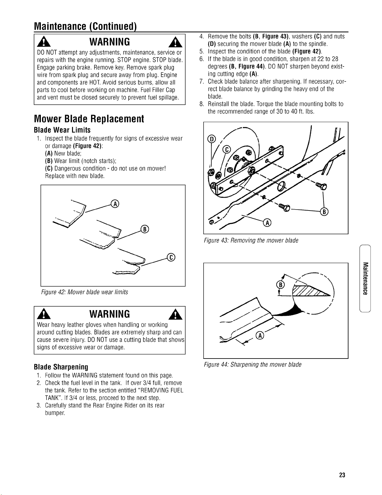
1. Inspectthe bladefrequently for signs of excessivewear
or damage(Figure 42):
(A) New blade;
(B) Wearlimit (notch starts);
(C) Dangerouscondition - do not use on mower!
Replacewith newblade.
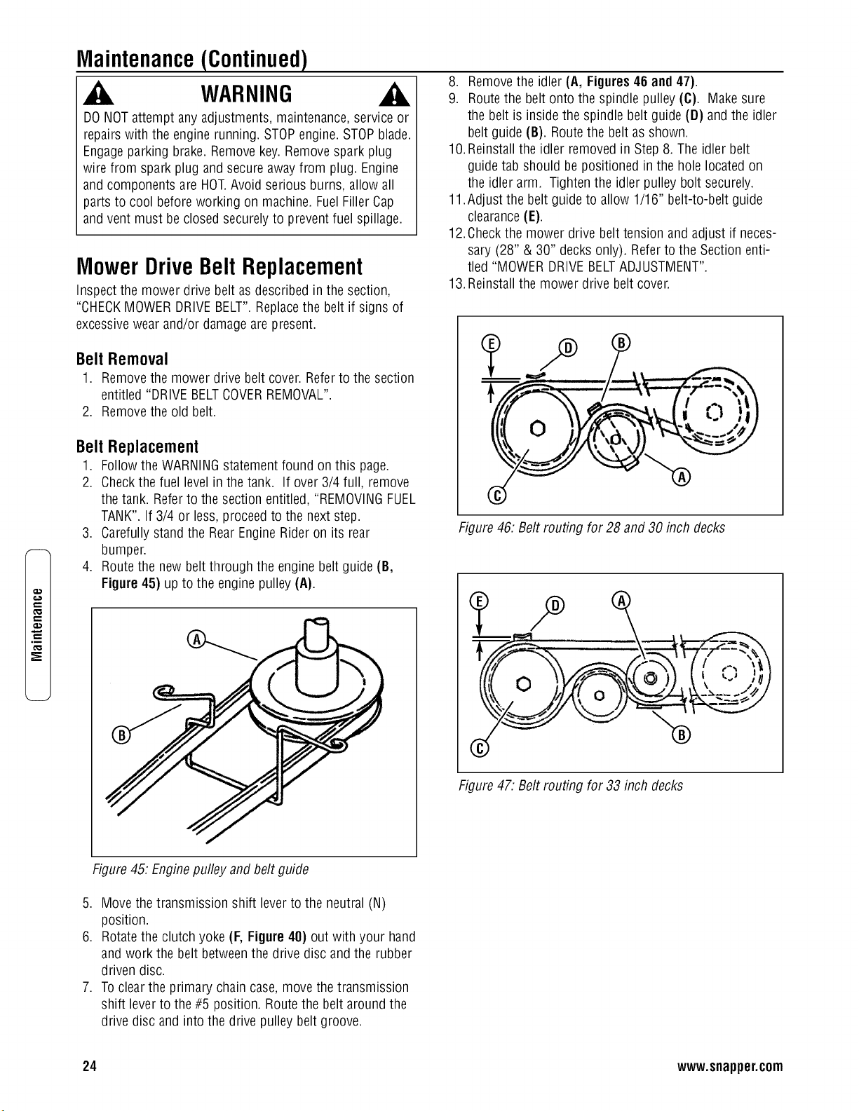
4. Removethe bolts (B, Figure43), washers (C) and nuts
(D) securing the mower blade (A) to the spindle.
5. Inspect the condition of the blade(Figure 42).
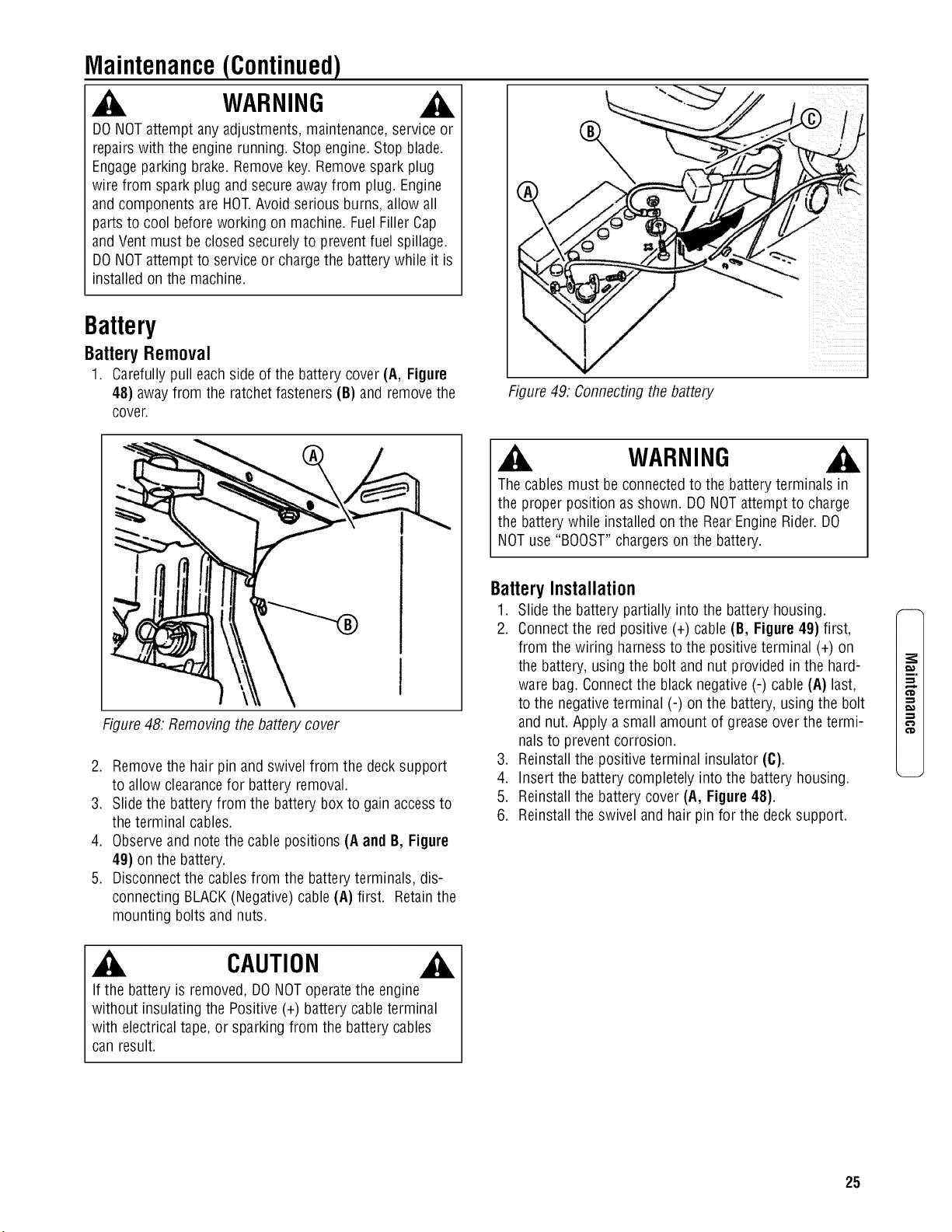
6. If the blade is in good condition, sharpenat 22 to 28
degrees(B, Figure44). DONOTsharpen beyondexist-
ing cutting edge (A).
7. Checkblade balanceafter sharpening. If necessary,cor-
rect blade balanceby grinding the heavyend of the
blade.
8. Reinstallthe blade.Torquethe blade mounting bolts to
the recommended rangeof 30 to 40 ft. Ibs.
Figure42: Mower blade wearlimits
WARNING
Wearheavy leathergloves when handling or working
around cutting blades. Bladesare extremely sharp and can
causesevere injury. DONOTusea cutting bladethat shows
signs of excessivewear or damage.
Figure 43. Removing themower blade
!
/
m.
CD
,-1
,-1
€'D
BladeSharpening
1. Followthe WARNINGstatementfound on this page.
2. Checkthe fuel levelin the tank. If over 3/4 full, remove
the tank. Referto the section entitled "REMOVINGFUEL
TANK".If 3/4 or less, proceedto the next step.
3. Carefullystand the RearEngineRider on its rear
bumper.
Figure 44. Sharpening the mower blade
23
,m
Maintenance(Continued)
WARNING
DONOTattempt anyadjustments, maintenance,service or
repairswith the engine running. STOPengine.STOPblade.
Engageparking brake. Removekey.Removespark plug
wire from spark plug and secureaway from plug. Engine
and components are HOT.Avoid serious burns, allow all
parts to cool beforeworking on machine.FuelFillerCap
and vent must beclosed securelyto prevent fuel spillage.
MowerDriveBeltReplacement
Inspect the mower drive belt asdescribed in the section,
8. Removethe idler (A, Figures46 and 47).
9. Routethe belt onto the spindle pulley (C). Make sure
the belt is insidethe spindle belt guide (D) and the idler
belt guide (B). Routethe belt as shown.
lO.Reinstall the idler removed in Step8. The idler belt
guide tab should be positioned in the hole located on
the idler arm. Tighten the idler pulley bolt securely.
11.Adjust the belt guide to allow 1/16" belt-to-belt guide
clearance(E).
12.Checkthe mower drive belt tension and adjust if neces-
sary (28" & 30" decksonly). Referto the Section enti-
tled "MOWER DRIVEBELTADJUSTMENT".
13.Reinstallthe mower drive belt cover.
"CHECKMOWERDRIVEBELT".Replacethe belt if signs of
excessivewear and/or damageare present.
Belt Removal
1. Removethe mower drive belt cover. Referto the section
entitled "DRIVEBELTCOVERREMOVAL".
2. Removethe old belt.
Belt Replacement
1. Followthe WARNINGstatementfound on this page.
2. Checkthe fuel levelin the tank. If over 3/4 full, remove
the tank. Referto the section entitled, "REMOVINGFUEL
TANK".If 3/4 or less, proceedto the next step.
©
3. Carefullystand the RearEngineRider on its rear
bumper.
4. Route the new belt through the engine belt guide (B,
Figure 45) up to the engine pulley (A).
Figure 46: Belt routing for 28 and 30 inch decks
t
Figure 47. Belt routing for 33 inch decks
Figure45. Enginepulley and belt guide
5. Movethe transmission shift leverto the neutral (N)
position.
6. Rotatethe clutch yoke (F, Figure 40) out with your hand
and work the belt betweenthe drive disc and the rubber
driven disc.
7. Toclearthe primary chain case,move the transmission
shift leverto the #5 position. Route the belt aroundthe
drive disc and into the drive pulley belt groove.
24 www.snapper.com
Maintenance(Continued)
WARNING
DONOTattempt anyadjustments, maintenance,service or
repairswith the engine running. Stop engine.Stop blade.
Engageparking brake. Removekey.Removespark plug
wire from spark plug and secureaway from plug. Engine
and components are HOT.Avoid serious burns, allow all
parts to cool beforeworking on machine.FuelFillerCap
and Vent must be closed securelyto prevent fuel spillage.
DONOTattempt to service or chargethe battery while it is
installed on the machine.
Battery
Battery Removal
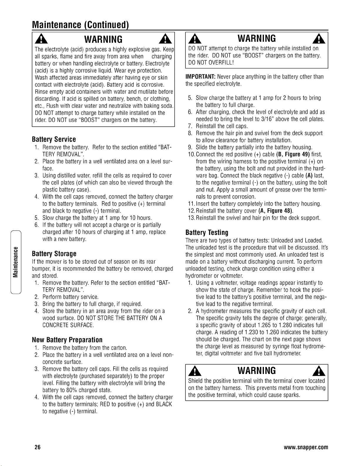
1. Carefullypull eachside of the battery cover (A, Figure
48) away from the ratchetfasteners (B) and removethe
cover.
Figure48. Removing the battery cover
2. Removethe hair pin and swivel from the deck support
to allow clearancefor battery removal.
3. Slidethe battery from the battery box to gain accessto
the terminal cables.
4. Observeand notethe cable positions (A and B, Figure
49) on the battery.
5. Disconnectthe cablesfrom the battery terminals, dis-
connecting BLACK(Negative)cable (A) first. Retainthe
mounting bolts and nuts.
CAUTION
If the battery is removed, DONOToperatethe engine
without insulating the Positive(+) battery cableterminal
with electrical tape, or sparking from the battery cables
can result.
Figure 49. Connectingthe battery
WARNING
Thecables must be connectedto the batteryterminals in
the proper position as shown. DONOTattempt to charge
the battery while installed on the RearEngine Rider.DO
NOTuse "BOOST"chargerson the battery.
Battery Installation
1. Slidethe battery partially into the battery housing.
2. Connectthe red positive (+) cable(B, Figure 49) first,
from the wiring harnessto the positive terminal (+) on
the battery, using the bolt and nut provided in the hard-
ware bag.Connectthe black negative(-) cable(A) last,
to the negativeterminal (-) on the battery, using the bolt
and nut. Apply a small amount of greaseover the termi-
nals to prevent corrosion.
3. Reinstallthe positive terminal insulator (C).
4. Insert the battery completely into the battery housing.
5. Reinstallthe battery cover (A, Figure 48).
6. Reinstallthe swivel and hair pin for the decksupport.
m,
co
25
,m
Maintenance(Continued)
WARNING
Theelectrolyte (acid) produces a highly explosive gas. Keep
all sparks, flame and fire awayfrom areawhen charging
battery or when handling electrolyte or battery. Electrolyte
(acid) is a highly corrosive liquid. Weareyeprotection.
Wash affected areasimmediately after havingeyeor skin
contact with electrolyte (acid). Batteryacid is corrosive.
Rinseempty acid containers with water and mutilate before
discarding. If acid is spilled on battery, bench, or clothing,
etc., Flushwith clearwater and neutralizewith baking soda.
DONOTattempt to charge battery while installed on the
rider.DONOTuse "BOOST"chargerson the battery.
BatteryService
1. Removethe battery.
Referto the section entitled "BAT-
TERYREMOVAL".
2. Placethe battery in a well ventilated areaon a levelsur-
face.
3. Usingdistilled water,refill the cells as required to cover
the cell plates (of which can also beviewed through the
plastic batterycase).
4. With the cell caps removed,connectthe battery charger
to the batteryterminals. Redto positive (+) terminal
and blackto negative (-) terminal.
5. Slow chargethe battery at 1 amp for 10 hours.
6. If the batterywill not accepta charge or is partially
chargedafter 10 hours of charging at 1 amp, replace
with a new battery.
BatteryStorage
If the mower isto be stored out of season on its rear
bumper, it is recommendedthe battery be removed, charged
and stored.
1. Removethe battery. Referto the section entitled "BAT-
TERYREMOVAL".
2. Perform battery service.
3. Bring the battery to full charge,if required.
4. Store the battery in an areaaway from the rider on a
wood surface. DONOTSTORETHE BATTERYONA
CONCRETESURFACE.
New BatteryPreparation
1. Removethe battery from the carton.
2. Placethe battery in a well ventilated areaon a levelnon-
concrete surface.
3. Removethe battery cell caps. Fillthe cells as required
with electrolyte (purchased separately)to the proper
level. Fillingthe battery with electrolyte will bring the
battery to 80% chargedstate.
4. With the cell caps removed,connectthe battery charger
to the batteryterminals; REDto positive (+) and BLACK
to negative(-) terminal.
WARNING
DONOTattempt to chargethe batterywhile installed on
the rider. DONOTuse"BOOST"chargers on the battery.
DONOTOVERFILL!
IMPORTANT:Never placeanything in the battery otherthan
the specified electrolyte.
5. Slow chargethe battery at 1 amp for 2 hours to bring
the battery to full charge.
6. After charging, check the levelof electrolyte and add as
neededto bring the levelto 3/16" abovethe cell plates.
7. Reinstallthe cell caps.
8. Removethe hair pin and swivel from the deck support
to allow clearancefor battery installation.
9. Slide the battery partially into the battery housing.
lO.Connect the red positive (+) cable(B, Figure 49) first,
from the wiring harnessto the positive terminal (+) on
the battery, using the bolt and nut provided in the hard-
ware bag.Connectthe black negative(-) cable(A) last,
to the negativeterminal (-) on the battery, usingthe bolt
and nut. Apply a small amount of greaseover the termi-
nalsto prevent corrosion.
11.Insert the battery completely into the battery housing.
12.Reinstallthe battery cover (A, Figure48).
13.Reinstallthe swivel and hair pin for the decksupport.
Battery Testing
Thereare two types of batterytests: Unloadedand Loaded.
Theunloaded test isthe procedurethat will be discussed. It's
the simplest and most commonly used.An unloadedtest is
madeon a batterywithout discharging current. Toperform
unloaded testing, checkcharge condition using either a
hydrometer or voltmeter.
1. Using avoltmeter,voltage readingsappear instantly to
show the stateof charge. Rememberto hookthe posi-
tive leadto the battery's positiveterminal, and the nega-
tive leadto the negativeterminal.
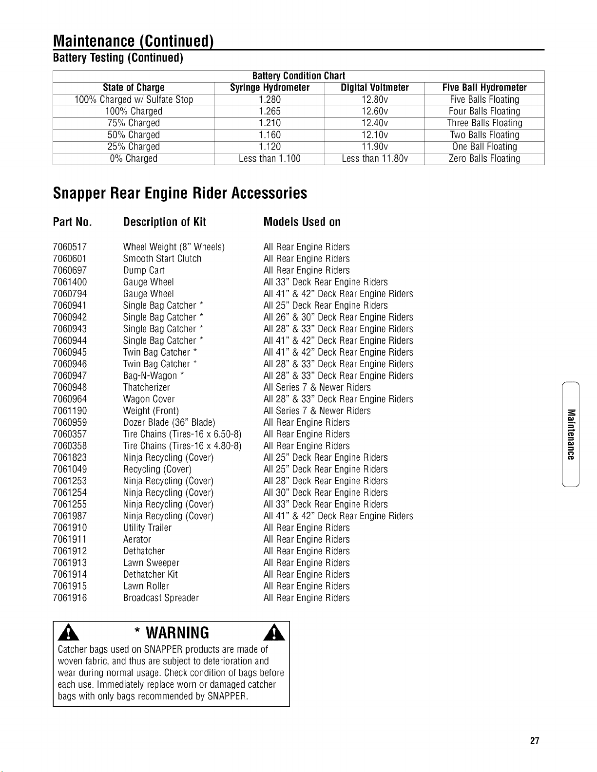
2. A hydrometer measuresthe specific gravity of eachcell.
Thespecific gravity tells the degreeof charge; generally,
a specific gravity of about 1.265 to 1.280 indicatesfull
charge. A readingof 1.230 to 1.260 indicatesthe battery
should be charged.The chart on the next pageshows
the charge levelas measuredby syringe float hydrome-
ter, digital voltmeter and five ball hydrometer.
WARNING
Shield the positive terminal with the terminal cover located
on the battery harness. This preventsmetal from touching
the positive terminal, which could cause sparks.
26 www.snapper.com
Maintenance(Continued)
Battery Testing (Continued)
BatteryConditionChart
State of Charge SyringeHydrometer Digital Voltmeter Five BallHydrometer
100% Chargedw/Sulfate Stop 1.280 12.80v FiveBallsFloating
100% Charged 1.265 12.60v Four Balls Floating
75% Charged 1.210 12.40v ThreeBalls Floating
50% Charged 1.160 12.10v Two Balls Floating
25% Charged 1.120 11.90v OneBallFloating
0% Charged Lessthan 1.100 Lessthan 11.80v Zero Balls Floating
SnapperRearEngineRiderAccessories
Part No. Description of Kit Models Used on
7060517 WheelWeight (8" Wheels) All RearEngine Riders
7060601 Smooth Start Clutch All RearEngine Riders
7060697 Dump Cart All RearEngine Riders
7061400 GaugeWheel All 33" DeckRearEngineRiders
7060794 GaugeWheel All 41" & 42" DeckRearEngine Riders
7060941 Single BagCatcher* All 25" DeckRearEngineRiders
7060942 Single BagCatcher* All 26" & 30" DeckRearEngine Riders
7060943 Single BagCatcher* All 28" & 33" DeckRearEngine Riders
7060944 Single BagCatcher* All41" & 42" DeckRearEngine Riders
7060945 Twin Bag Catcher* All 41" & 42" DeckRearEngine Riders
7060946 Twin Bag Catcher* All 28" & 33" DeckRearEngine Riders
7060947 Bag-N-Wagon * All 28" & 33" DeckRearEngine Riders
7060948 Thatcherizer All Series7 & Newer Riders
7060964 WagonCover All 28" & 33" DeckRearEngine Riders
7061190 Weight (Front) All Series7 & Newer Riders
7060959 Dozer Blade(36" Blade) All RearEngine Riders
7060357 Tire Chains(Tires-16 x 6.50-8) All RearEngine Riders
7060358 Tire Chains(Tires-16 x 4.80-8) All RearEngine Riders
7061823 Ninja Recycling (Cover) All 25" DeckRearEngineRiders
7061049 Recycling (Cover) All 25" DeckRearEngineRiders
7061253 Ninja Recycling (Cover) All 28" DeckRearEngineRiders
7061254 Ninja Recycling (Cover) All 30" DeckRearEngineRiders
7061255 Ninja Recycling (Cover) All 33" DeckRearEngineRiders
7061987 Ninja Recycling (Cover) All 41"& 42" DeckRearEngine Riders
7061910 Utility Trailer All RearEngine Riders
7061911 Aerator All RearEngine Riders
7061912 Dethatcher All RearEngine Riders
7061913 Lawn Sweeper All RearEngine Riders
7061914 Dethatcher Kit All RearEngine Riders
7061915 Lawn Roller All RearEngine Riders
7061916 BroadcastSpreader All RearEngine Riders
m,
¢o
€o
* WARNING
Catcherbags usedon SNAPPERproducts are madeof
woven fabric, and thus are subject to deterioration and
wear during normal usage.Checkcondition of bagsbefore
eachuse. Immediately replaceworn or damagedcatcher
bagswith only bags recommendedby SNAPPER.
27
,m
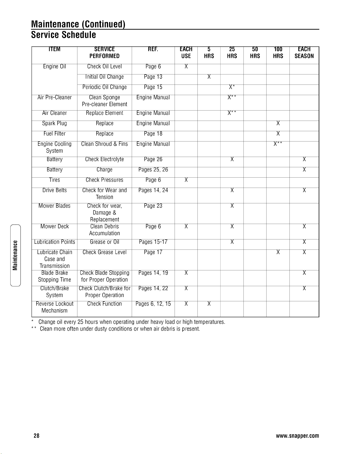
Maintenance(Continued)
ServiceSchedule
ITEM
EngineOil
Air Pre-Cleaner
Air Cleaner
Spark Plug
FuelFilter
EngineCooling
System
Battery
Battery
Tires
Drive Belts
Mower Blades
Mower Deck
Lubrication Points
Lubricate Chain
Caseand
Transmission
Blade Brake
Stopping Time
Clutch/Brake
System
ReverseLockout
Mechanism
SERVICE
PERFORMED
CheckOil Level
Initial Oil Change
Periodic Oil Change
CleanSponge
Pre-cleanerElement
ReplaceElement
Replace
Replace
CleanShroud & Fins
CheckElectrolyte
Charge
CheckPressures
Checkfor Wearand
Tension
Checkfor wear,
Damage&
Replacement
CleanDebris
Accumulation
Greaseor Oil
CheckGreaseLevel
Check BladeStopping
for Proper Operation
CheckClutch/Brakefor
Proper Operation
CheckFunction
REF.
Page6
Page13
Page15
EngineManual
EngineManual
EngineManual
Page18
EngineManual
Page26
Pages25, 26
Page6
Pages14, 24
Page23
Page6
Pages15-17
Page17
Pages14, 19 X
Pages14, 22 X
Pages6, 12, 15 X
EACH 5 25 50 100 EACH
USE HRS HRS HRS HRS SEASON
X_
X**
X_
X
X
X
X
X
X
X**
X
* Changeoil every 25 hours when operating under heavyload or high temperatures.
** Cleanmore often under dusty conditions or when air debris is present.
X
X
X
X
X
X
X
X
28 www.snapper.com

Maintenance(Continued)
Maintenance/ReplacementParts
EngineSpeedControl (Briggs Engine)
EngineSpeedControl (Kohler Engine)
EngineSpeedControl (HondaEngine)
Ulutch/BrakeCable
Clutch/BrakeCable(33" DeckModels Only)
BrakeCable
28" Cutter Blade(Standard - Not Air Lift Compatible)
28" Cutter Blade(Standard - Air Lift Compatible)
28" Cutter Blade(Mulching)
28" Cutter Blade(Ninja - Quad Edge)
30" Cutter Blade(Standard - Not Air Lift Compatible)
30" Cutter Blade(Standard - Air Lift Compatible)
30" Cutter Blade(Ninja - Quad Edge)
33" Cutter Blade(Standard - Not Air Lift Compatible)
33" Cutter Blade(Standard - Air Lift Compatible)
33" Cutter Blade(Mulching)
33" Cutter Blade(Ninja - Quad Edge)
&ir Lift Kit (28" and 33" Decks)
_,irLift Kit (30" Deck)
Engineto Cutting DeckBelt (28" and 30" Decks)
Engineto Cutting DeckBelt (33" Decks)
Rubber Drive Disc
Parts Manualfor RearEngine Rider Series23
Parts Manualfor RearEngine Rider Series23 (California Models)
7022751
7074320
7075089
7022449
7074131
7072648
7035635
7019515
7016980
7026453
NiA
7018069
7026565
7034168
7019523
7016982
7024741
7060480
7060735
7022252
7043844
7053103
7006152
7006265
m,
€'D
29
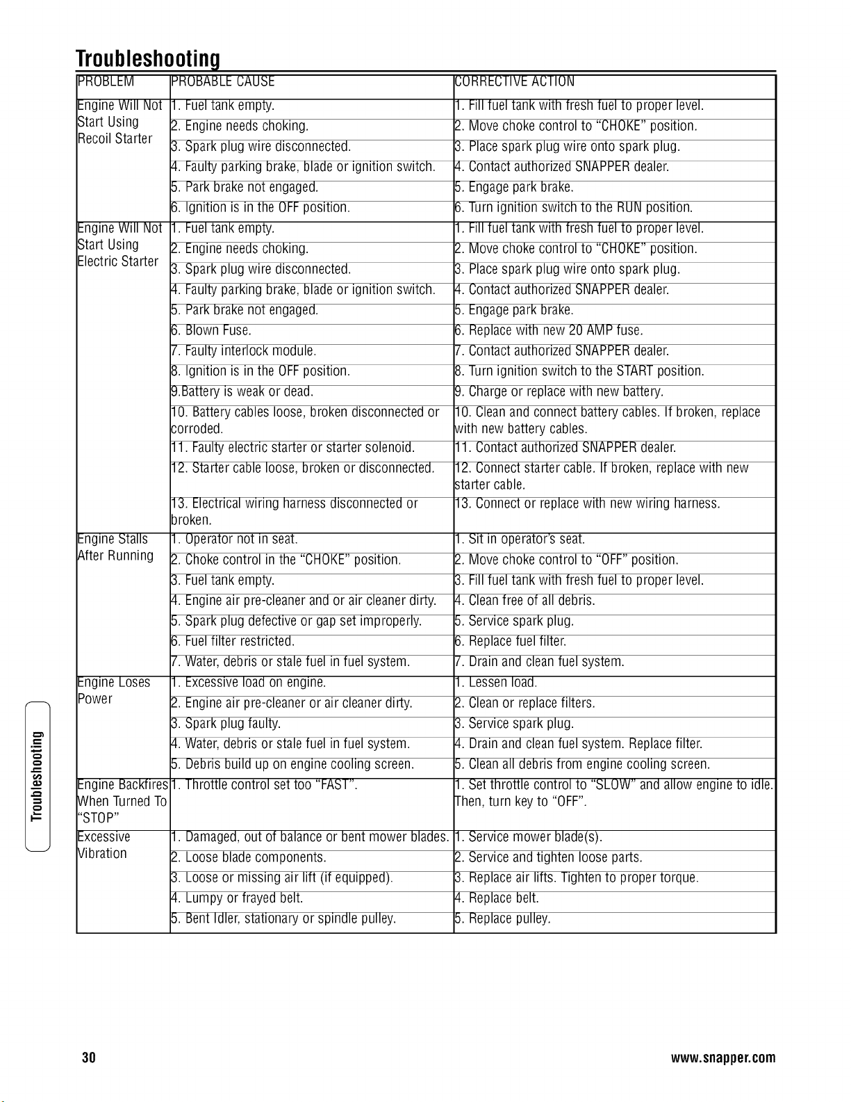
,n
t_
Troubleshooting
PROBLEM PROBABLECAUSE
EngineWill Not
Start Using
Recoil Starter
EngineWill Not
Start Using
ElectricStarter
EngineStalls
After Running
EngineLoses
Power
EngineBackfires
When TurnedTo
"STOP"
Excessive
Vibration
•
2.
3.
4.
5.
6.
1.
2.
3.
4.
5.
6.
7.
Fueltank empty.
Engineneedschoking•
Spark plug wire disconnected•
._ORRECTIVEACTION
•Fillfuel tank with fresh fuel to proper level•
2.Move choke control to "CHOKE"position•
3.Placespark plug wire onto spark plug.
Faultyparking brake, blade or ignition switch• 1.
Park brakenot engaged• 5.
Ignition is in the OFFposition• 3.
Fueltank empty.
Engineneedschoking• 2.
Spark plug wire disconnected• 3.
Faultyparking brake, blade or ignition switch• 1.
Park brakenot engaged• 5.
Blown Fuse. 3.
Faultyinterlock module• 7.
Contact authorized SNAPPERdealer•
Engagepark brake•
Turnignition switch to the RUNposition•
•Fillfuel tank with fresh fuel to proper level•
Move choke control to "CHOKE"position•
Placespark plug wire onto spark plug.
Contact authorized SNAPPERdealer•
Engagepark brake•
Replacewith new 20 AMP fuse.
Contact authorized SNAPPERdealer•
8. Ignition is in the OFFposition• 3.Turnignition switch to the STARTposition•
9.Battery is weak or dead. _).Chargeor replacewith new battery•
10. Batterycables loose, broken disconnectedor
corroded•
11. Faultyelectric starter or starter solenoid•
12. Starter cable loose, broken or disconnected•
13. Electricalwiring harnessdisconnected or
broken•
1. Operatornot in seat.
2. Chokecontrol in the "CHOKE"position•
3. Fueltank empty.
4. Engineair pre-cleanerand or air cleanerdirty•
5. Spark plug defective or gap set improperly•
6. Fuelfilter restricted•
7. Water,debris or stale fuel in fuel system•
1. Excessiveload on engine•
2. Engineair pre-cleaneror air cleanerdirty.
3. Spark plug faulty•
4. Water,debris or stale fuel in fuel system•
5. Debris build up on engine cooling screen•
1. Throttle control set too "FAST"•
1. Damaged,out of balanceor bentmower blades•
2. Loose bladecomponents•
3. Loose or missing air lift (if equipped)•
4. Lumpy or frayed belt.
5. Bent Idler, stationary or spindle pulley•
0. Cleanand connect batterycables• If broken, replace
Nith new battery cables•
1. Contact authorized SNAPPERdealer•
2. Connectstarter cable• If broken, replacewith new
_tartercable•
3. Connector replacewith newwiring harness•
•Sit in operator's seat.
__.Move choke control to "OFF"position•
3.Fillfuel tank with fresh fuel to proper level•
_,.Cleanfree of all debris•
5.Service spark plug.
5.Replacefuel filter•
7.Drain and cleanfuel system•
•Lessenload.
2.Cleanor replacefilters•
3.Service spark plug.
1.Drain and cleanfuel system• Replacefilter•
5.Cleanall debris from enginecooling screen•
•Setthrottle control to "SLOW" andallow engineto idle.
rhen, turn key to "OFF".
•Servicemower blade(s).
__.Service andtighten loose parts•
3.Replaceair lifts• Tighten to proper torque•
1.Replacebelt.
5.Replacepulley•
30 www.snapper.com
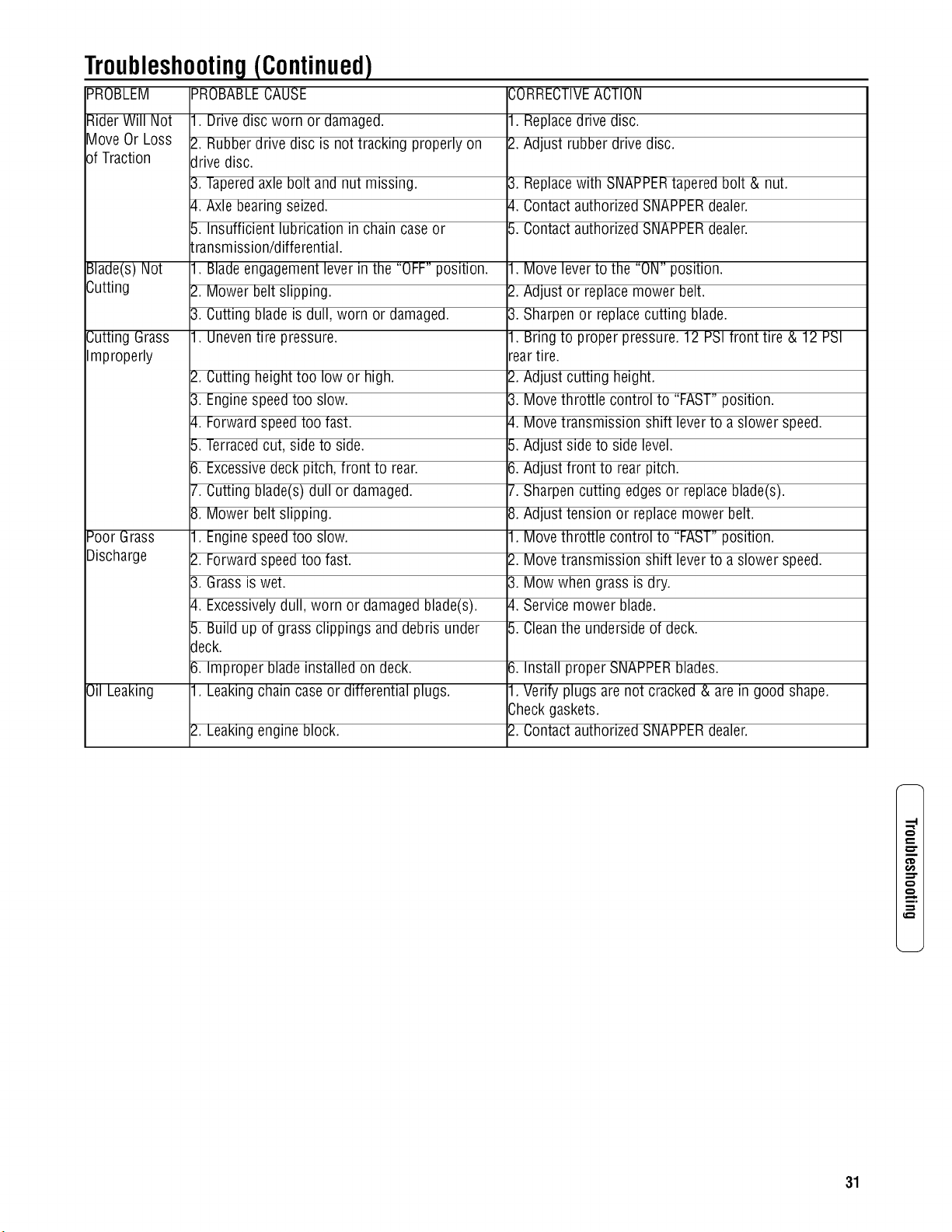
Troubleshooting(Continued)
PROBLEM PROBABLECAUSE
Rider Will Not 1. Drive disc worn or damaged.
Move Or Loss 2. Rubberdrive disc is nottracking properly on
of Traction drive disc.
3. Taperedaxle bolt and nut missing.
4. Axle bearing seized.
5. Insufficient lubrication in chain case or
transmission/differential.
Blade(s) Not 1. Bladeengagementlever in the "OFF"position.
Cutting 2. Mower belt slipping.
3. Cutting blade is dull, worn or damaged.
1. Uneventire pressure.Cutting Grass
Improperly
Poor Grass
Discharge
Oil Leaking
.
3.
4.
5.
6.
7.
8.
1.
2.
3.
4.
Cutting heighttoo low or high. 2.
Enginespeedtoo slow. 3.
Forward speedtoo fast. 4.
Terracedcut, side to side. 5.
Excessivedeck pitch, front to rear. 6.
Cutting blade(s)dull or damaged. 7.
Mower belt slipping. 8.
Enginespeedtoo slow. 1.
Forward speedtoo fast. 2.
Grass is wet. 3.
Excessivelydull, worn or damagedblade(s). 4.
5. Build up of grass clippings and debris under
deck.
6. Improper blade installed on deck.
1. Leakingchain caseor differential plugs.
2. Leakingengine block.
CORRECTIVEACTION
1. Replacedrive disc.
2. Adjust rubber drive disc.
3. Replacewith SNAPPERtapered bolt & nut.
4. Contact authorized SNAPPERdealer.
5. Contact authorized SNAPPERdealer.
1. Move leverto the "ON" position.
2. Adjust or replacemower belt.
3. Sharpen or replacecutting blade.
1. Bring to proper pressure.12 PSIfront tire & 12 PSI
reartire.
Adjust cutting height.
Movethrottle control to "FAST"position.
Movetransmission shift leverto a slower speed.
Adjust side to side level.
Adjust front to rear pitch.
Sharpen cutting edgesor replaceblade(s).
Adjust tension or replacemower belt.
Movethrottle control to "FAST"position.
Movetransmission shift leverto a slower speed.
Mow when grass is dry.
Service mower blade.
5. Cleanthe undersideof deck.
6. Install proper SNAPPERblades.
1. Verify plugs are not cracked& are in good shape.
Checkgaskets.
2. Contact authorized SNAPPERdealer.
¢D
t.#}
mo
31
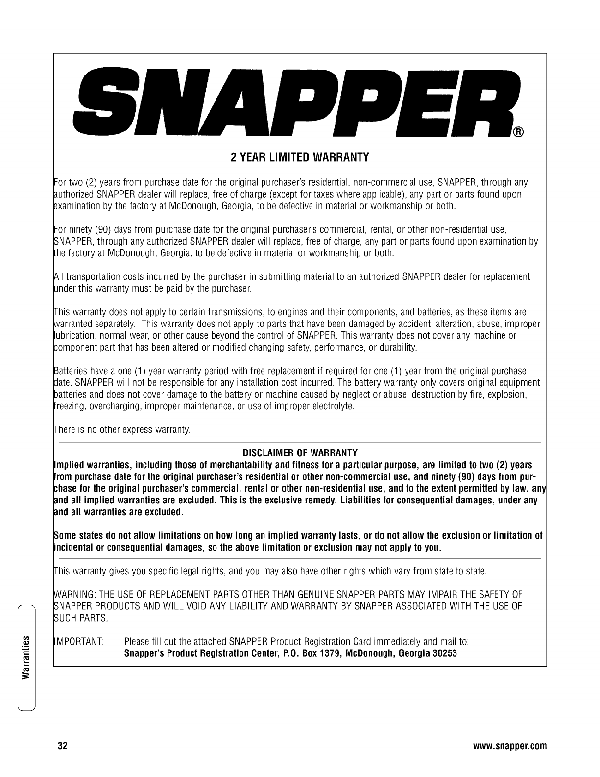
t_
.m
x,..
2 YEAR LIMITED WARRANTY
Fortwo (2) years from purchase datefor the original purchaser's residential,non-commercial use, SNAPPER,through any
authorizedSNAPPERdealerwill replace,free of charge (exceptfor taxes where applicable), any part or parts found upon
_xaminationby the factory at McDonough, Georgia,to be defective in material or workmanship or both.
Forninety (90) days from purchasedatefor the original purchaser'scommercial, rental,or other non-residential use,
SNAPPER,through any authorizedSNAPPERdealerwill replace,free of charge, any part or parts found upon examination by
Lhefactory at McDonough, Georgia,to be defective in material or workmanship or both.
&ll transportation costs incurred by the purchaser in submitting material to an authorized SNAPPERdealer for replacement
underthis warranty must be paid bythe purchaser.
This warranty does not apply to certain transmissions, to engines and their components, and batteries, asthese items are
_varrantedseparately. This warranty doesnot applyto parts that havebeendamaged byaccident, alteration, abuse, improper
lubrication, normal wear,or other cause beyondthe control of SNAPPER.This warranty does not cover anymachine or
3omponent part that has beenalteredor modified changing safety,performance, or durability.
Batterieshavea one (1) year warranty period with free replacementif required for one (1) year from the original purchase
date.SNAPPERwill not be responsiblefor anyinstallation cost incurred. Thebattery warranty only covers original equipment
batteriesand does not cover damageto the battery or machinecaused by neglect or abuse, destruction by fire, explosion,
freezing,overcharging, improper maintenance,or useof improper electrolyte.
Thereis no other expresswarranty.
DISCLAIMEROFWARRANTY
Implied warranties, includingthoseof merchantabilityand fitnessfor a particularpurpose,are limited to two(2) years
frompurchasedatefor the originalpurchaser'sresidential or othernon-commercialuse, and ninety(90) daysfrom pur-
chase for theoriginal purchaser'scommercial,rental or othernon-residentialuse, and tothe extentpermittedbylaw, any
andall impliedwarrantiesare excluded.This isthe exclusiveremedy.Liabilitiesfor consequentialdamages,underany
andall warrantiesare excluded.
Somestates donot allow limitations onhow longan implied warrantylasts, or do notallow the exclusionor limitation of
incidentalor consequentialdamages,sothe abovelimitation or exclusionmay notapplyto you.
This warranty gives you specific legal rights, and you may also haveother rights which vary from state to state.
WARNING:THE USEOFREPLACEMENTPARTSOTHERTHANGENUINESNAPPERPARTSMAYIMPAIRTHESAFETYOF
SNAPPERPRODUCTSAND WILL VOIDANY LIABILITYANDWARRANTYBYSNAPPERASSOCIATEDWITH THE USEOF
SUCHPARTS.
IMPORTANT:
Pleasefill out the attachedSNAPPERProduct Registration Cardimmediately and mail to:
Snapper'sProductRegistrationCenter, P.O.Box1379, IVIcDonough,Georgia30253
32 www.snapper.com
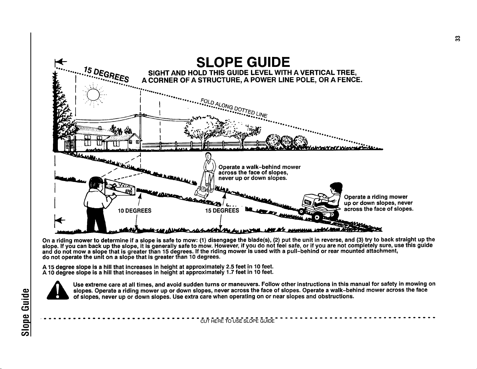
O_
Bm
O
m
r#3
4- SLOPE GUIDE
........ :..../.b" DE_D_... SIGHT AND HOLD THIS GUIDE LEVEL WITH A VERTICAL TREE,
I ".... -'..'.._S A CORNER OF A STRUCTURE, A POWER LINE POLE, OR A FENCE.
j ........................
...... .....................
!
I
I
Operate a walk-behind mower
across the face of slopes,
never up or down slopes.
10 DEGREES 15 DEGREES
Operate a riding mower
up or down slopes, never
across the face of slopes.
On a riding mower to determine if a slope is safe to mow: (1) disengage the blade(s), (2) put the unit in reverse, and (3) try to back straight up the
slope. If you can back up the slope, it is generally safe to mow. However, if you do not feel safe, or if you are not completely sure, use this guide
anddo not mow a slope that is greater than 15 degrees. If the riding mower is used with a pull-behind or rear mounted attachment,
do not operate the und on a slope that is greater than 10 degrees.
A 15 degree slope is a hill that increases in height at approximately 2.5 feet in 10 feet.
A 10 degree slope is a hill that increases in height at approximately 1.7 feet in 10 feet.
Use extreme care at all times, and avoid sudden turns or maneuvers. Follow other instructions in this manual for safety in mowing on
slopes. Operate a riding mower up or down slopes, never across the face of slopes. Operate a walk-behind mower across the face
of slopes, never up or down slopes. Use extra care when operating on or near slopes and obstructions.
................................. _U'T_E'R_fO'U§E'_GP__&_D'E.................................

Notes
34 www.snapper.com

Notes
35

Notes
36 www.snapper.com

Notes
37
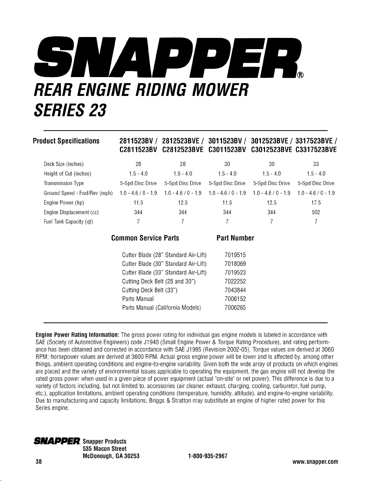
REARENGINERIDINGMOWER
SERIES23
Product Specifications
2811523BV / 2812523BVE /
C2811523BV C2812523BVE
3011523BV/
C3011523BV
3012523BVE/3317523BVE/
C3012523BVE C3317523BVE
DeckSize(inches) 28 28 30 30 33
Heightof Cut(inches) 1.5- 4.0 1.5- 4.0 1.5- 4.0 1.5- 4.0 1.5- 4.0
TransmissionType 5-SpdDiscDrive 5-SpdDiscDrive 5-SpdDiscDrive 5-SpdDiscDrive 5-SpdDiscDrive
GroundSpeed-Fwd/Rev(mph) 1.0-4.6/0-1.9 1.0-4.6/0-1.9 1.0-4.6/0-1.9 1.0-4.6/0-1.9 1.0-4.6/0-1.9
EnginePower(hp) 11.5 12.5 11.5 12.5 17.5
EngineDisplacement(cc) 344 344 344 344 502
FuelTankCapacity(qt) 7 7 7 7 7
Part NumberCommonServiceParts
Cutter Blade (28" StandardAir-Lift)
Cutter Blade (30" StandardAir-Lift)
Cutter Blade (33" StandardAir-Lift)
Cutting DeckBelt (28 and 30")
Cutting DeckBelt (33")
Parts Manual
Parts Manual (California Models)
7019515
7018069
7019523
7022252
7043844
7006152
7006265
EnginePower RatingInformation:The gross power rating for individual gasengine models is labeled in accordancewith
SAE(Societyof Automotive Engineers)codeJ1940 (Small Engine Power& Torque Rating Procedure),and rating perform-
ancehasbeen obtainedand corrected in accordancewith SAEJ1995 (Revision 2002-05). Torquevalues are derived at 3060
RPM; horsepowervalues are derived at 3600 RPM.Actual gross engine power will be lower and is affected by, among other
things, ambient operatingconditions and engine-to-engine variability. Givenboth the wide array of products on which engines
are placedand the variety of environmental issues applicableto operating the equipment, the gas enginewill not developthe
ratedgross power when used in a given pieceof power equipment (actual "on-site"or net power). This difference is due to a
variety of factors including, but not limited to, accessories(air cleaner,exhaust, charging, cooling, carburetor,fuel pump,
etc.), application limitations, ambient operating conditions (temperature, humidity, altitude), and engine-to-enginevariability.
Dueto manufacturing and capacity limitations, Briggs & Stratton may substitute an engine of higher ratedpower for this
Seriesengine.
m,_J_G_II2JID_'.II_.SnapperProducts
535 Macon Street
McDonough, GA30253
38
1-000-935-2967
www.snapper.com