1. BEFORE INSTALLATION
1-1. THE FOLLOWING SHOULD ALWAYS BE OBSERVED FOR SAFETY
!"#$ %&'(&')%$*%&!')
"+
,(-./012304
)"5&%6%/"# &$!'7&%&!'#$)
INSTALLATION MANUAL
ENGLISH
Required Tools for Installation
"
5
)
*
18-9:
%+
;8:
9<1=8>:?
$>40
($>40
@$>40
$>40
"
MSZ-GL06/09/12/15NA
MSY-GL09/12/15NA
;
■ Do not install the unit by yourself (user).
&N
+
■ Follow the instructions detailed in the installation manual.
&N6
■ When installing the unit, use appropriate protective equipment and tools for
safety.
N
■ Install the unit securely in a place that can bear the weight of the unit.
&
N
■ Perform electrical work according to the installation manual and be sure to use
an exclusive circuit. Do not connect other electrical appliances to the circuit.
&
■ Ground the unit correctly.
76
7
■ Do not damage the wires.
7
■ Be sure to shut off the main power when setting up the indoor P.C. board or
wiring.
■ -
&
■
&?
■ Do not use intermediate connection of the power cord or the extension cord.
Do not connect many devices to one AC outlet.
&
■
%N
■ When plugging the power supply plug into the outlet, make sure that there is
no dust, blockage, or loose parts both in the outlet and on the plug. Verify that
the power supply plug is completely in the outlet.
&
&
■ Securely attach the electrical cover to the indoor unit and the service panel to
the outdoor unit.
&<
■ When installing, relocating, or servicing the unit, make sure that no substance
!"#$%&
?N%
&
■ Do not discharge the refrigerant into the atmosphere. Check that the refriger-
ant gas does not leak after installation has been completed. If refrigerant leaks
during installation, ventilate the room.
&
&I
■ Use appropriate tools and piping materials for installation.
%$>40 42$=='
N
■ When pumping down the refrigerant, stop the compressor before disconnecting
the refrigerant pipes.
&
■ When installing the unit, securely connect the refrigerant pipes before starting
the compressor.
&
■ '+
&I
■ Install the unit according to national wiring regulations.
■ Depending on the installation area, install a Ground Fault Interrupt (GFI) circuit
breaker.
&(&8(&:
■ Perform the drainage/piping work securely according to the installation manual.
&<
■
%N
■ Do not install the outdoor unit where small animals may live.
&
H
CAUTION
8N:
WARNING
8N:
J!7#5
MSZ-GL06NA MSZ-GL09NA
MSY-GL09NA
MSZ-GL12NA
MSY-GL12NA
MSZ-GL15NA
MSY-GL15NA
&'7!!$*'&%
"8@"3 )#3K: =0D<=10420
J 8 : 40
85 : 8 : 0-2
!*%7!!$*'&%
"8@"3 )#3K: =0D<=10420
J?K8:8 : E 49 49 49
J 8 : E . . 40
85 : 8 : E 090 090 090
8$5 :8 :
J)T E 2= 22 ->
J)/ E >. >. 2D
85$ :8 :
J)T E -- D= .1
J)/ E 24 24 D9
&6$U8;:
&6!U74=6=>@8":
E J)T6(502' $
"
!
J
&
&
8:
+ 4<>8219: 0014980D: 9<428D:
3
00>9)6
1<D8.9=: 0014980D: 9<428D:
4<=84=-: 0014980D: 9<428D:
5
" J)T<J)/6(50.<4=<49' 298=0:?
3 J)T<J)/6(50.<4=<49' >084=:?
' 40?
"
*=98-9: '+
#?=98-9:
+
8$:
$ J)T<J)/6(50.<4=<49' 40DK98=0<:
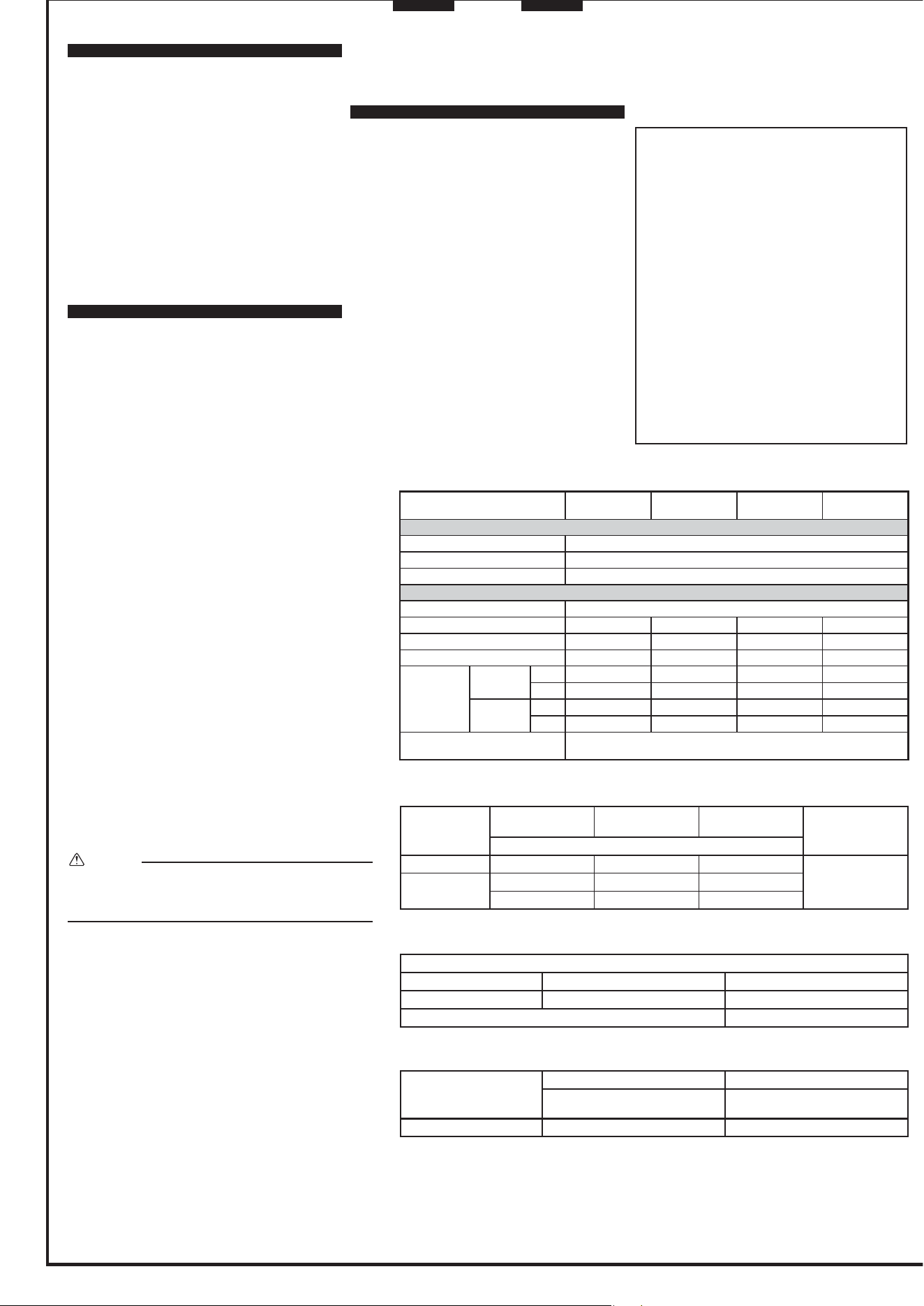
1-3. SPECIFICATIONS
1-3-1. POWER SUPPLY AND INDOOR/OUTDOOR
WIRE CONNECTION
"?
;
;
)
Connecting wires and the ground wire
* J ;(4>
J ;(4>
*200@
*
E
Power supply cable and ground wire
*J ;(4>
*
E
Note:
;6
$N&?=98-9:
8$>40 :+
8%
=9F-9G:
%I
$
$
1-3-2. REFRIGERANT PIPES
%
$>8400:
CAUTION
8
:#?
1-2. SELECTING THE INSTALLATION LOCATION
INDOOR UNIT
;I
;8:
!
;?7?
6
;
184:%@
!
%@ +
&I
8
:
;
;
Note:
&
REMOTE CONTROLLER
;
;
)>84=:I
8VW
VW:%
Note:
&I
OUTDOOR UNIT
; ? &
?
;I
;
8:
;
;
&
;40 81:
%@!
%@6
+
&K
"
&
<I
Note:
&
?
Note:
;6
'
<?
%?
I
;I
;?
;
8
:
)
;
;6++
;@!6
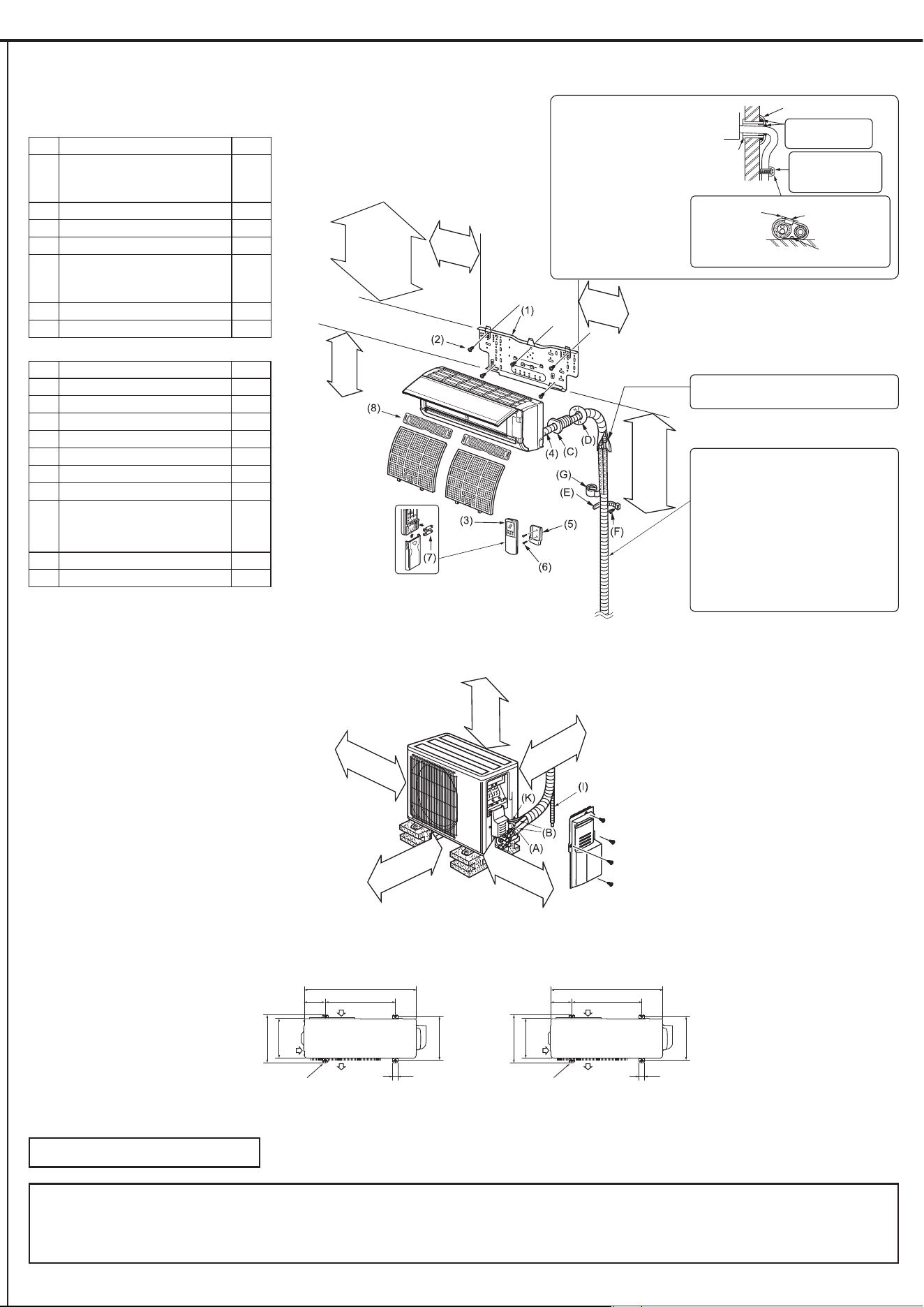
1-4. INSTALLATION DIAGRAM
ACCESSORIES
A&B
84: & 4
8=:
6
>C=9
9
81: ; 4
8>: 86: 4
89: $ 4
82:
)
19C428:
=
8-: 8 :81: =
8D: =
FIELD-SUPPLIED PARTS
8 :
&<E4
4
8: #? 4
8: ; 4
87: ; 4
8#: " =9
8: )8#:>C=0 =9
8(: " 4
83: " 4
8&:
7
8"@4.<1=F49G
"@
@"42:
=9
8,: $ 4
8H: "*44
*
+
&
;
8:
?
"
8#:
*
8:<
8 :
;87:
)
83:
6
8#:
8:
6
;
=9<1=
8=0:
-
D
%?!!5
10
$I
Note:
E4"<8 :
8H:184:
%@
>61<D
8440:
16-<D
8400:
=64<D89>
:<
964<D8410:
8:
1<D840:
Drain piping for outdoor unit
&K
77K
%)<
K
*U *U
1464<=
4.644<42
416.<42
4464<>
=61<D
C
41<42
4=64=61<>
46.<42
D00
900
=640
C
=4
1>>9
=D9
490
>0
10>61=9
9649<42
9.-984D
=1:I
>8400:
4>8190:
>8400:
E=
E= >8400:
E1 ;=
D8=00:E1
J
8J46.<42F>0G:
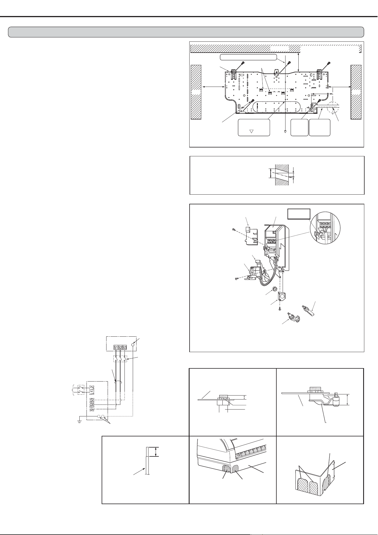
2-1. ATTACHING THE INSTALLATION PLATE
84:K?
8=:
%84:
;
84:-<42?41<42L-<42?4844C=0L44
C=2:84-61<>F>90G:
&86:
;
!
2-2. DRILLING
4:7
=:7M18-9:%2<1=.<1=89-:
1:&8:
2-3. CONNECTING WIRES FOR INDOOR UNIT
Note:
;6
4:$8$964:
=:"
1:$?
>:$
9: 8 :<N8 :
%<N
1<D840:84:#N
461<42810:8=:
2:"81:
?
-:"<8 :81:
6
?
D:
.:$
40: ?8>:
?89:$?
51<D
840:
N
5
2<1=6.<1=
896-:
O1
8-9:
&
?
5
#N
8:
#N
8:
5461<42
810:
?
$?
$?
4
=
1
> 9
?
$?
$?
5
&84:
"
M1
8-9:
>61<D
8440:
16-<D
8400:
=64<D89>:
964<D8410:
8:
;
8=:
E)
&
E
E
964<D8410:
INDOOR UNIT
%
208/230 V AC
1phase, 60 Hz
(
EE
7
E
OUTDOOR UNIT
(EE
(
"
=0D<=10@
4=
203K
%
4
Remark:
E
+
EE *6
%=
# #?
7
8:
;
(
2. INDOOR UNIT INSTALLATION
5
4.<1=
849:
2-4-2. DRAIN PIPING
&?
86:
%84:
&6
8&:8=:
;
81:
7
7
;
;
;
;
%
7
4614<1=
890:
7
7
)
&74.<1=
849:
7
3
&7461<42
810:
&
7
N
=-6.<42
8-0:
4 = 1
5+
(
8>:
&<
8 :
"8(:
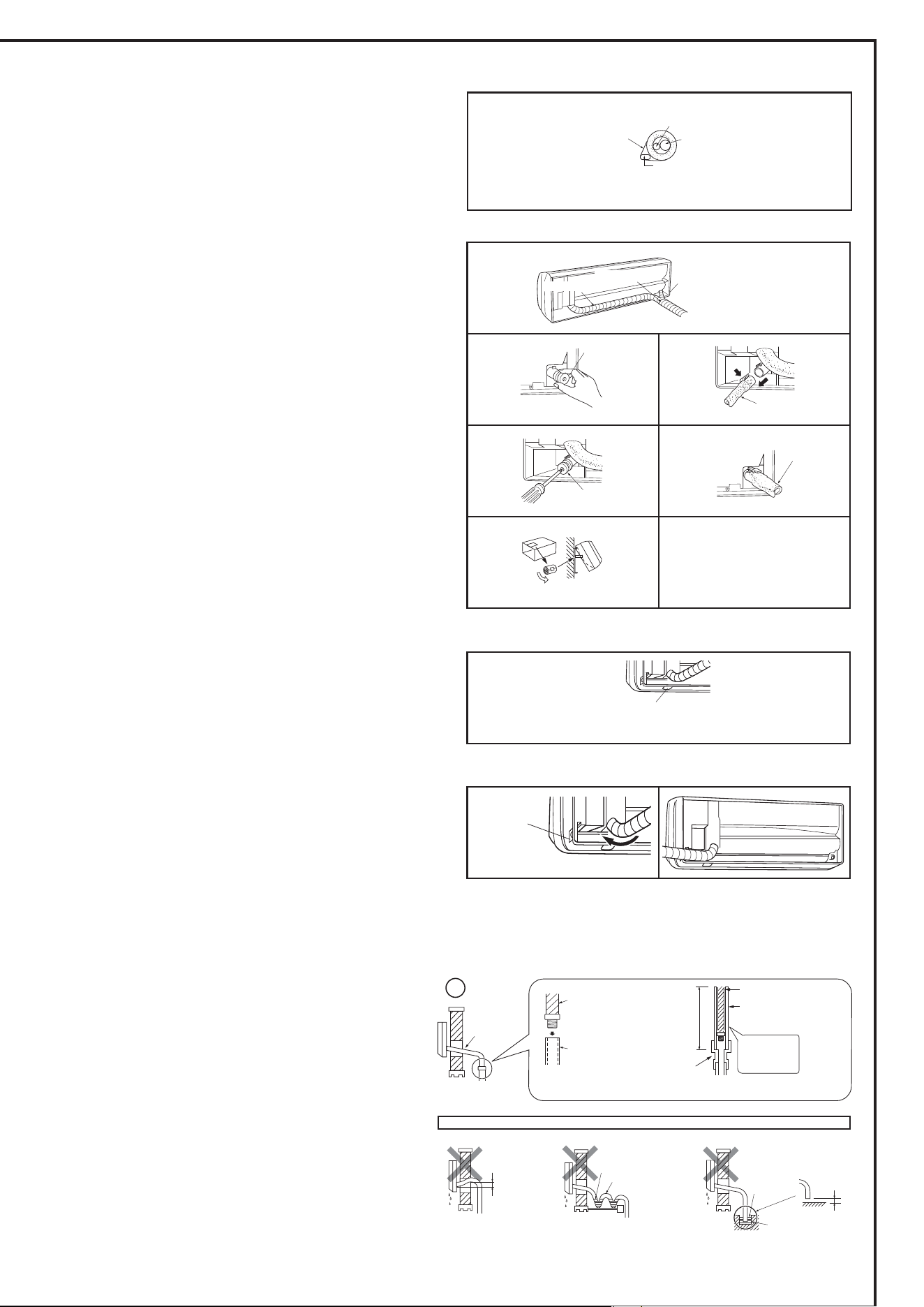
2-4. PIPE FORMING AND DRAIN PIPING
2-4-1. PIPE FORMING
"
J
7
;86
:
Note:
J
Left or left-rear piping
Note:
4:"8>:
8>:4<1*
8>:
=:"84:
3?
1:"8=:
3
>:"
81:
&
9:&8>:
N
2:&8:
84:%
-:?
89:
D:?8:
.: 84:
$?
7
7
7
7
4 =
1
>
9
"8(:
8>:
Rear or bottom piping
4:"
8(:
=:&8:
84:
1:84:
>: 84:
Right piping
Note:
8$=61:
4:"
8(:
=:&8:
84:
1:84:
>: 84:
%
$
?
$?
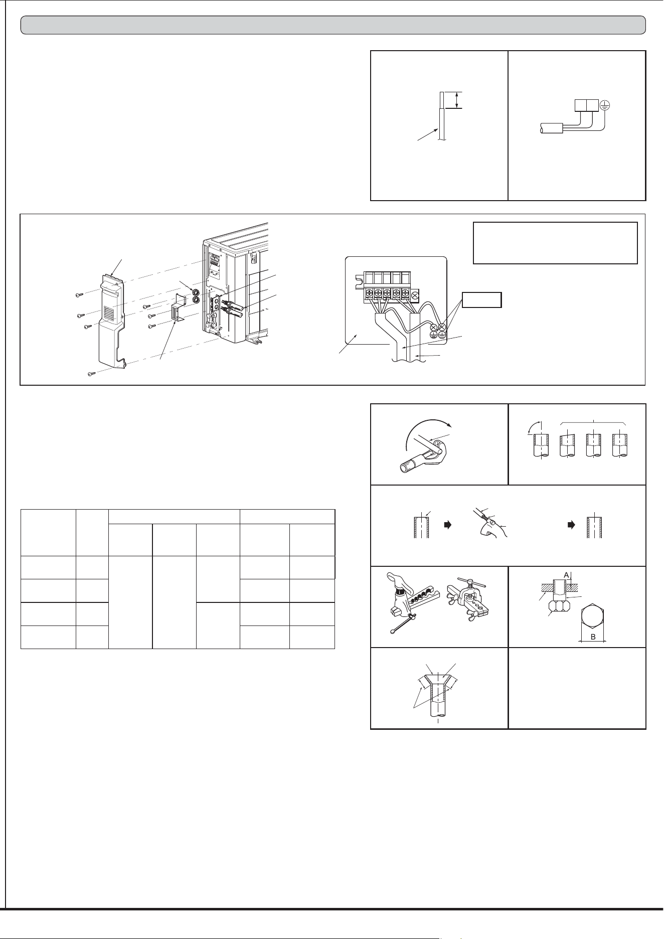
3-1. CONNECTING WIRES FOR OUTDOOR UNIT
4:$
=:$
1:
>:<8 :8H:
%
9:5<8 :6
8H:
?
2:
-:&
D:&
3-2. FLARE CONNECTION
4:84=:
=:$
81:
1:$I
>:8>9:)
8:
9:
I2
&I
5
J
8J16-<DF400G:
Power supply cord (K)
L1
L2
4.<1=
849:
(
90°
%
'
4 =
)
"
>
1
)
#
&6
9
2
;
*
7
%
Power supply cord (K)
&<
8 :
)
5
%
3. OUTDOOR UNIT INSTALLATION
(
"6
8:
8:
8: %+
$>40
$==
;
$==
6
8:
'
M4<>8219:
=4<1=
84-:
000=
8009:
00>
002
840
49:
002
00D
849
=0:
4041
84>04D0:
41-4--
M1<D8.9=:
-<D
8==:
=910
8190>=0:
1>1>4=
M4<=84=-:
464<1=
8=2:
00D
040
8=0
=9:
12>=
89009-9:
>.092>
M9<D849DD:
469<1=
8=.:
9>9D
8-90D00:
-19-D>
3-3. PIPE CONNECTION
I+816=:
;I
7
Indoor unit connection
+
8,:I76
#?+
%1>I
*+N
#?I
Outdoor unit connection
N
&
+
4-4. EXPLANATION TO THE USER
*!"#$ %&'(&')%$*%&!')?
8
:
$!"#$ %&'(&')%$*%&!')
4-2. TEST RUN
4:&<
=:"#!);%10
&09
<8 :
!!58-9SF=>SG!!5:
1:%#!);
5#7$
Checking the remote (infrared) signal reception
"!<!'81:
"!<!'
!
1
4-3. AUTO RESTART FUNCTION
%+;
8$
:
#
8#!);:
Caution:
#!);
&
To the user
?
&6
$
3-4. INSULATION AND TAPING
4:N
=:
1: 8(:
;
6
WARNING
When installing the unit, securely connect the refrigerant pipes before starting
the compressor.
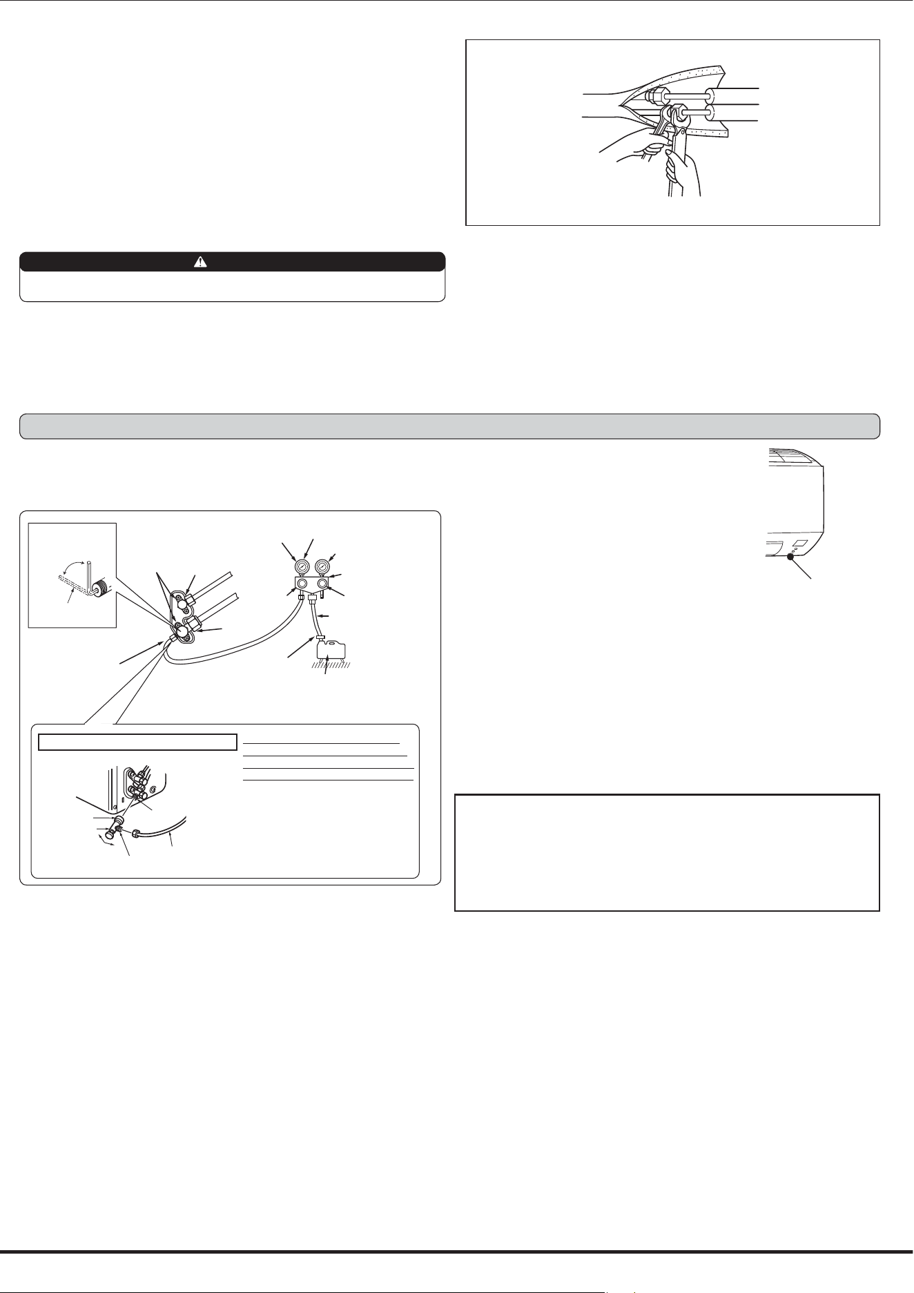
4-1. PURGING PROCEDURES AND LEAK TEST
4:$8%
:5
=:
)
( )
)
8%+49
==64.2
=.>'=00
100Z:
@8
I:
(
8$>40 :
8$>40 :
[4>-F(G
8[0404J:
3
5
33
I
8$>40 :
E
E!
3?
"
;
?
%
)
!
;
7
)
8%+4041
6&41-4--'
4>04D0:
E>9
1:#>000)
'8'=:0")&(
>:# 4900 '8'=:
0")&(
9:#900
2:10
-:)9004
D:+!
.:$461
+!
40:$
44:5
)5&\*&7
"
8$>40 :
4. PURGING PROCEDURES, LEAK TEST, AND TEST RUN
5-3. PUMPING DOWN
;
4:
=:+
1:
0F(G
80J:
>:)!!5
%!!5
< 49<
#!);8%!!5
10:
9:
8040F(G80090J::
2:)!!5
%#!);5#7
$
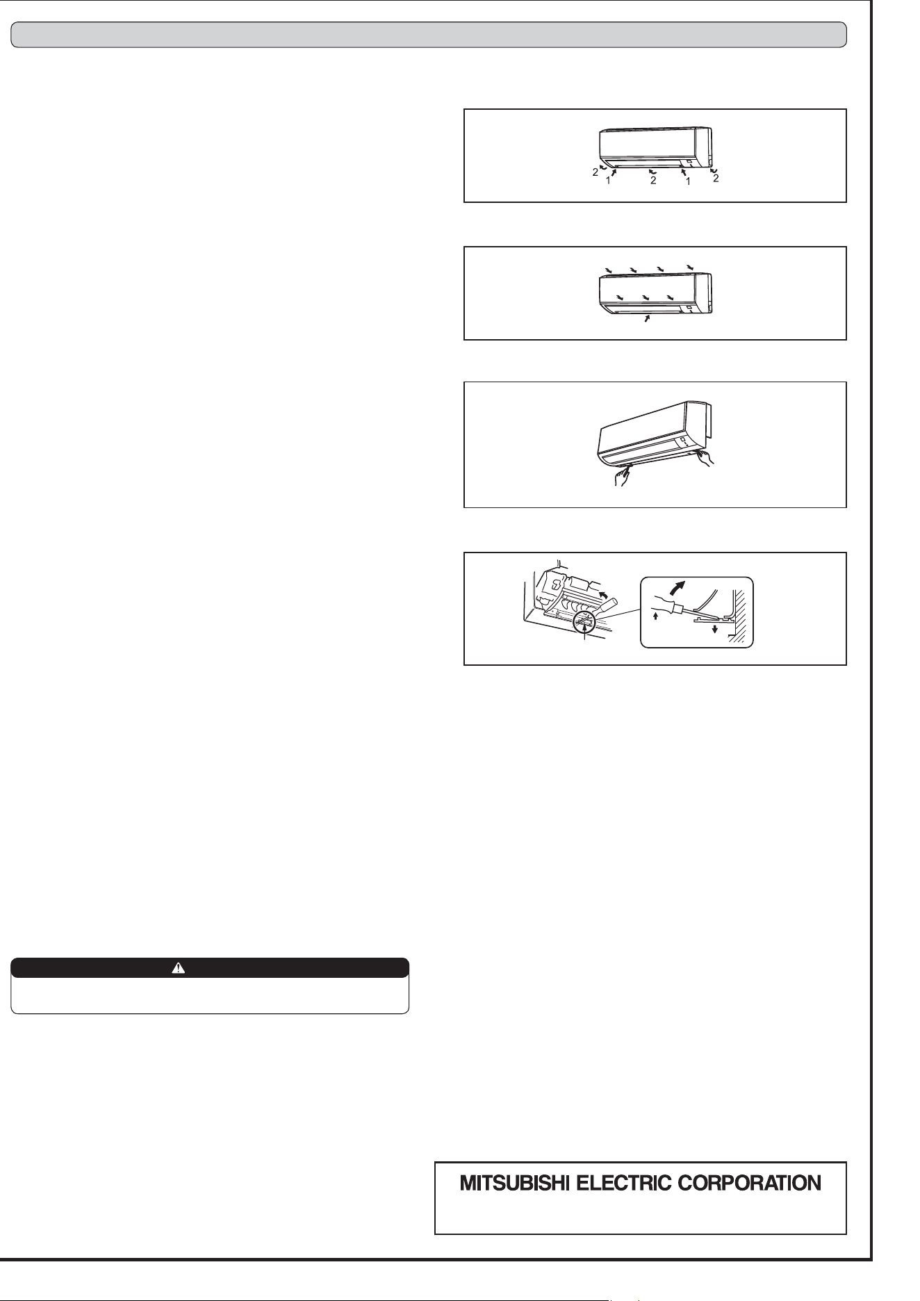
5-1. REMOVING AND INSTALLING THE PANEL
ASSEMBLY
Removal procedure
4:$
=:$
5-2. REMOVING THE INDOOR UNIT
$
;
"
5
)+
Installation procedure
4:&
=:6
If the above method cannot be used
$%?+
%
When pumping down the refrigerant, stop the compressor before discon-
necting the refrigerant pipes. The compressor may burst if air etc. get into it.
WARNING
3# 7!&#U%!H/!57(=6-61J $*'!*3&3&/!7 6H*
%!H/!4006D140, " '
5. RELOCATION AND MAINTENANCE