Loading ...
Loading ...
Loading ...
EZ LINK SYSTEM DUAL INSTALLATION
65
EZ LINK CABLE CONNECTION
The references in steps 8 to 11 are to the ‘Control Board with EZ Link Connection’ diagram on page 66. To
connect the EZ Link cable to the water heaters:
1. Close any hot taps and ensure the burners on both water heaters are not operating.
2. Switch off the electrical supply at the power outlet to each water heater.
3. Remove the top and bottom cover strips to gain access to the front panel screws by pressing on the two
ridged finger points and gently pulling forward.
4. Remove the screws holding the front panel to the jacket on each water heater.
5. Gently disengage the front panel and pull forward to remove from each water heater.
6. Remove the screw securing the Control Board on each water heater. Discard the screws.
7. Gently pull forward the Control Board on each water heater to improve access to the cable connector.
8. Connect one end of the EZ Link cable to the first water heater.
If a controller(s) is connected to one of the water heaters, then this is the ‘master’ or ‘first’ water heater.
Draw the cable through the cable grommet on the underside of the water heater.
Plug the cable into the four pin connector marked “E” in the mid right-hand side of the Control Board
(refer to the Control Board diagram).
The connector will only fit one way.
Press until the connector snaps into place.
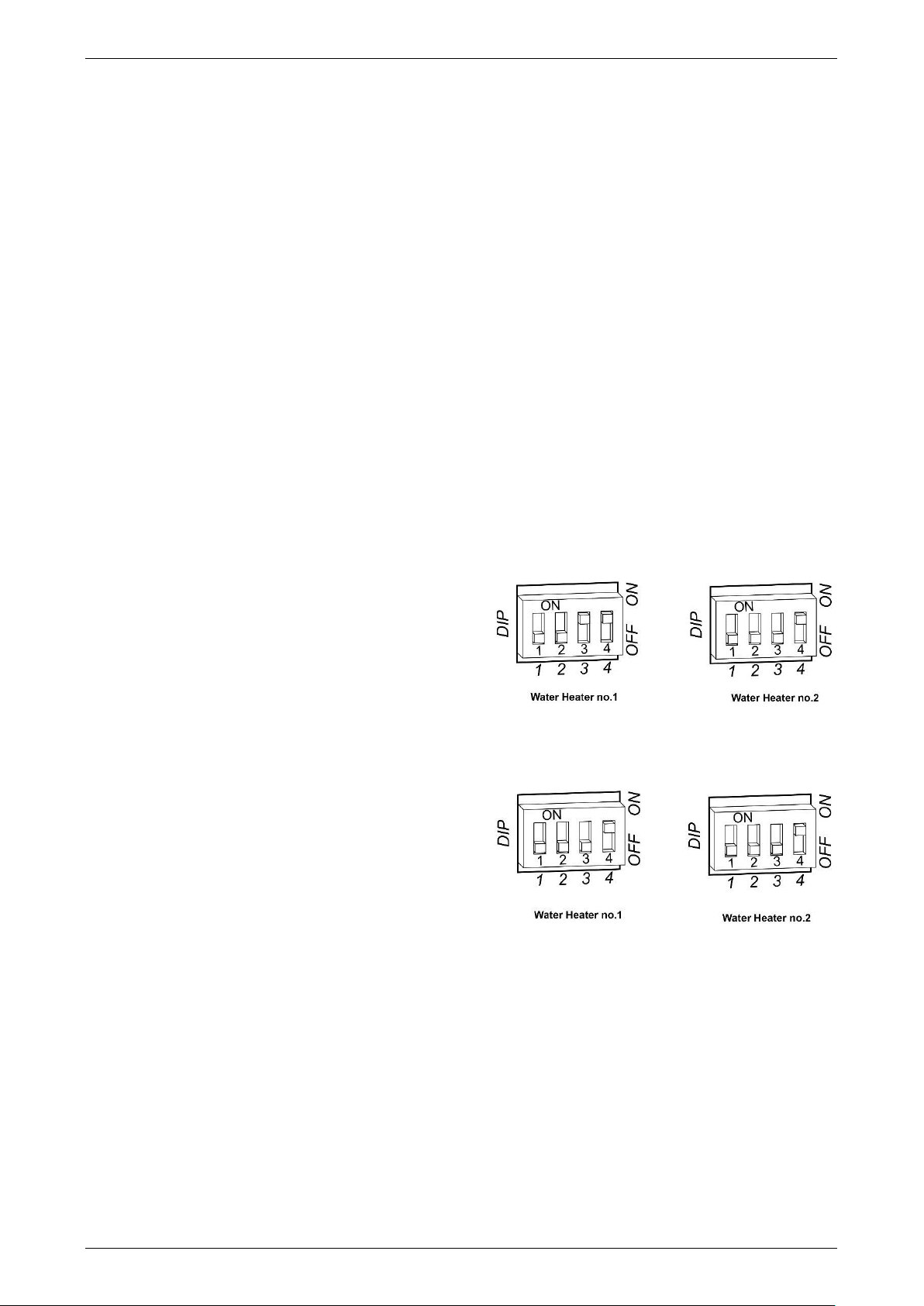
9. Switch DIP switch 4 to the on (up) position on the
first water heater (refer to the Control Board
diagram).
If a temperature controller is not installed, then
also switch DIP switch 3 to the on (up) position
on the first water heater.
10. Connect the other end of the EZ Link cable to the
second water heater.
Draw the cable through the cable grommet on
the underside of the water heater.
Plug the cable into the connector marked “E” in
the mid right-hand side of the Control Board
(refer to the Control Board diagram).
The connector will only fit one way.
Press until the connector snaps into place.
11. Switch DIP switch 4 to the on (up) position on the
second water heater (refer to the Control Board
diagram).
12. Refit the control board and secure the EZ Link cable with the clamp and screw provided to the top right of
the Control Board to each water heater. This also secures the Control Board in position.
13. Refit the front panel and screws to each water heater.
14. Refit the cover strips to the top and bottom of the front panel by inserting the two posts into the two
recesses and gently pushing into position.
15. Check the main gas isolation valve and the isolation valves at the gas inlet to each water heater are fully
open.
16. Switch on the electrical supply at the power outlets to the water heaters.
dip switch settings
without temperature controller
dip switch settings
with temperature controller connected
Loading ...
Loading ...
Loading ...