
SafetyInstructions& Operator'sManual for
21" STEELDECK
WALKMOWERS
SERIES19
Models
\
2167519B(7800174)
P2167519B(7800175)
P2187519BV(7800176)
P2187519BVE(7800178)
P216019KWV (7800193)
J
NOTE:Specifications are correctat time of printing and are subjectto changewithout notice.
* Actual sustainedengine power will likely be lower dueto operating limitations and environmentalfactors. Please refer to 'EnginePower Rating Information' for
further details.
McDonough, GA;_ 30;253 U_S_A_
Manual No. 7101294 (I.R. 1/26/2007)
TP lO0-5257-1R-WB-N

ThankYoufor purchasingthis quality-built Snapperproduct.We're pleasedthat you placedyour
confidencein the Snapperbrand.Whenoperatedand maintainedaccordingto the instructions in this
manual,your Snapperproduct will providemanyyears of dependableservice.
Thismanualcontainssafety information to makeyou awareof the hazardsand risks associatedwith the
machineand how to avoidthem. This machineis designedand intendedonlyfor finish cutting of
establishedlawnsand is not intendedfor any other purpose. It is importantthat you readand understand
theseinstructions thoroughly beforeattemptingto start or operatethis equipment.Savethese
instructions for future reference.
PRODUCT REGISTRATION
IMPORTANT: KEEPTHIS INFORMATION FORYOUR PERSONAL RECORDS
(Complete the following information on your Snapper purchase)
Date of Purchase
Retailer
Retailer'sPhoneNumber
Equipment
Model Number
Serial Number
Engine
Model .Type. Trim
It is veryimportantthatyouregisteryourpurchasewithSnapperto ensurewarrantycoverage.Please
mail yourproductregistrationcardto:
Snapper at P.O. Box777, McDonough, Georgia 30253.
Oryou mayregisteronline at www.snapper.com.
Youcan contactusat ourwebsite,or if youwouldlike tospeakwith a CustomerService
Representative,call usat the SnapperCustomerRelationsCenterat 1-800-935-2967. Forfaster
servicepleasehaveyourSerial NumberandModel Numberavailable.
SNAPPERis a trademarkof
SimplicityManufacturing,Inc.
PortWashington,WI, USA.
Briggs& StrattonYardPower Products Group
Copyright© 2007, Briggs& StrattonCorporation
Milwaukee, WI, USA. All RightsReserved.
TableofContents
Operator Safety ................................................ 2
Important OperatorSafety Instructions .................................. 2
Featuresand Controls ........................................... 4
Operation .................................................... 5
Pre-Start Checklist .................................................. 5
Starting & Stopping Engine& Blades .................................... 5
Propelling Mower ................................................... 6
HandleHeight Adjustment ............................................ 6
Cutting HeightAdjustment ............................................ 7
Recycling Operation ................................................. 7
Removingthe Recycling Cover ......................................... 7
Installing the DischargeDeflector ....................................... 8
Installing the Grass BagAdapter ........................................ 8
Installing the Recycling Plug ........................................... 9
Installing the Grass Bag .............................................. 9
Maintenance ................................................. 10
ChangeEngine Oil .................................................. 10
CheckTransmission Grease .......................................... 10
CheckMower Blade ................................................ 11
CheckEngineDrive Belt ............................................. 11
CheckTransmission Belt ............................................. 11
Service - Periodic .................................................. 11
Engine ........................................................... 11
Air Filter ......................................................... 11
Engine Oil ........................................................ 11
Storage Procedure ................................................. 11
Mower Blade Replacement ........................................... 12
BladeSharpening .................................................. 12
Wheel DriveControl Adjustment ....................................... 13
Driven and Drive Disc Service ......................................... 14
Belt Service ....................................................... 17
Engine Drive Belt Replacement ........................................ 17
Transmission BeltReplacement ....................................... 18
Battery Service .................................................... 19
Service Schedule................................................... 20
Troubleshooting............................................... 21
Warranty .................................................... 22
WARNING
Batteryposts, terminals and relatedaccessoriescontain
lead and lead compounds, chemicals known to the State of
Californiato cause cancer and birth defects or other
reproductiveharm. Wash handsafter handling.
WARNING
Engineexhaust,some of its constituents, and certain
vehicle components contain or emit chemicals known to
the State of California to causecancer or other reproductive
harm.
CD
"11
CD
CD
t_
,-1
t_
CD
mo
,-1
CD
,-1
,-1
CD
,..z.
--z
CD
t_
x,.,
,A
ImportantOperatorSafetyInstructions
WARNING:This powerful cutting machine is capableof amputating handsand feet and canthrow objects
that can cause injury and damage! Failureto comply with the following SAFETYinstructions could result in
serious injury or deathto the operator or other persons.The owner of the machine must understand these
instructions and must allow only persons who understandthese instructions to operate machine.Each
personoperating the machine must be of sound mind and body and must not be under the influence of any
substance,which might impair vision, dexterity or judgment. If you haveany questions pertaining to your
machinewhich your dealer cannot answer to your satisfaction, call or write the Customer Service
Departmentat SNAPPER,IVIcDonough,Georgia30253. Phone:(1-800-935-2967).
Protection for Children
Tragic accidents canoccur if the operator is not alert to the
presenceof children. Children areoftenattractedto the
machine andthe mowing activity. Neverassumethat
children will remain whereyou last saw them.
1. KEEPchildren out of the mowing area and under the
watchful careof a responsible adult other than the operator.
2. DONOTallow children in yard when machine is operated
andturn machine OFFif anyoneenters the area.
3. DONOTallow pre-teenagechildren to operate machine.
4. ALLOW only responsible adults & teenagerswith mature
judgment under close adult supervision to operate machine.
5. DONOTpull mower backwards unless absolutely
necessary.LOOKand SEEbehindanddown for children,
pets and hazards beforeand while backing.
6. USEEXTRACAREwhen approaching blind corners,
shrubs, trees, or other objects that may obscure vision.
SlopeOperation
1. Slopesare a major factor relatedto slip and fall acci-
dents,which can result in severe injury. All slopes require
extra caution. If you feel uneasyon a slope, DONOTmow
it.
2. Mow across slopes, neverup-and-down. Exercise
extremeCAUTIONwhen changing directions on slopes. DO
NOTmow steep slopes or other areaswhere stability or
traction is in doubt. Referto the Slope Guideat the endof
this manual.
3. Useextra carewith gcrass catchers or other attach-
ments; these affect the handling and the stability of the
machine.
Preparation
(ContinuedFromPrevious Column)
4. Handlefuel with extra care. Fuelsareflammable and
vapors are explosive. Useonly an approvedfuel container.
DONOTremovefuel capor addfuel with engine running.
Add fuel outdoors only with engine stopped and cool. Clean
spilled fuel and oil from machine. DONOTsmoke.
5. Checkthe areato be mowed and removeall objects such
as toys, wire, rocks, limbs and other objects that could
cause injury if thrown by bladeor interfere with mowing.
Also notethe location of holes, stumps, and other possible
hazards.
6. Keeppeople and pets out of the mowing area.
Immediately,STOPBlade,Stop engine and Stop mower if
anyone entersthe area.
7. Checkshields, deflectors, switches, blade controls and
other safety devicesfrequently for proper operation and
location.
8. Make sureall safety decals are clearly legible. Replaceif
damaged.
9. Protectyourself when mowing and wear safety glasses, a
dusk mask, long pants,and substantial footwear. DONOT
mow barefooted or with sandals.
10. Know how to STOPbladeand engine quickly in
preparationfor emergencies.
11. Use extra carewhen loading or unloading the machine
into a trailer or truck.
12. Checkgrass catchercomponents frequently for signs of
wear or deterioration and replaceas neededto prevent
injury from thrown objects going through weak or torn
spots.
Preparation
1. Read,understand, andfollow instructions and warnings
in this manualand on the mower, engine and attachments.
Knowthe controls and the proper useof the mower before
starting.
2. Only mature, responsible persons shall operatethe
machine and only after proper instruction.
3. Data indicatesthat operators age 60 and above,are
involved in a large percentageof mower-related injuries.
Theseoperators should evaluatetheir ability to operatethe
mower safely enough to protect themselvesand others
from serious injury.
Safe Handling of Gasoline
Toavoid personal injury or property damage, useextreme
care in handling gasoline. Gasolineis extremely flammable
and the vapors are explosive.
1. Extinguishall cigarettes, cigars, pipes and other sources
of ignition.
2. Use only an approvedfuel container.
3. DONOTremovefuel cap or add fuel with the engine
running. Allow the engineto cool before refueling.
4. DONOTrefuelthe machine indoors.
5. DONOTstore the machine or fuel container inside where
there is an open flame, spark or pilot light such as on a
water heateror other appliances.
2 www.snapper.com

ImportantOperatorSafetyInstructions(Continued)
Safe Handling of Gasoline
(ContinuedFromPrevious Page)
6. DONOTfill fuel containers inside a vehicle or on atruck
or trailer bed with a plastic liner. Always placethe contain-
erson the ground away from the vehicle beforefilling.
7. Removegas-poweredequipment from the vehicle or
trailer and refuelit on the ground. If this is not possible,
then refuelequipment using a portablecontainer, rather
than a gasolinedispenser nozzle.
8. DONOTstart gas poweredequipment in enclosedvehi-
cles or trailers.
9. Keepthe nozzlein contact with the rim of the fuel tank or
container opening at all times until fueling is complete. DO
NOTusea nozzle lock-open device
10. If fuel is spilled on clothing, change clothing
immediately.
11. DONOToverfill a fuel tank. Replacefuel cap and tighten
securely.
Operation
1. DONOTput handsor feet near or under rotating parts.
Keepclearof discharge areawhile engine is running.
2. STOPenginewhen crossing gravel drives, walks, or
roads, and under anyconditions where thrown objects
might be a hazard.
3. Mow only in daylight or good artificial light.
4. DONOToperatemower while under the influence of
alcohol or drugs.
5.After striking a foreign object or if mower vibrates
abnormally,STOPthe engine,disconnect and secure spark
plug wire. Inspect the mower for anydamageand repair the
damagebeforestarting.
6. DONOTmow near drop offs, ditches or embankments.
Operatorcould lose footing or balance.
7. STAYALERTfor holes and other hidden hazards.Tall
grass can hide obstacles. Keepawayfrom ditches,
washouts, culverts, fencesand protruding objects.
8. DONOTmow on wet grass. Always be sure of your
footing. Keepa firm hold on the handleand walk, neverrun.
Slipping could cause injury.
9.ALWAYSstay behind handlewhen engine (motor) is
running.
10. DONOTleavethe machinewith the engine running.
STOPBLADEand STOPENGINEbeforeleavingthe opera-
tors position for any reason.
11. Beforecleaning, repairing or inspecting make certain
engine,blade and all moving parts haveSTOPPED.
Disconnectand secure spark plug wire awayfrom plug to
prevent accidentalstarting.
12. STOPengineandwait until the bladecomes to com-
pleteSTOPbefore removing grass bag and/or clearing
grass.
Operation
(ContinuedFromPrevious Column)
13. DONOToperatemower without the entire grass catch-
er, or guards in placedischarge guard, rearguard or other
safety devicesin placeand working. DONOTpoint dis-
charge at people,passing cars, windows or doors.
14. DONOTdischarge material against a wall or obstruc-
tion. Material may ricochet back towards the operator.
15. Slow down beforeturning.
16. Watchout for traffic when near or crossing roadways.
17. DONOToperateengine in enclosedareas. Engine
exhaust gasescontain carbon monoxide, a deadly poison.
18. Onlyuse accessoriesapprovedby the manufacturer.
See manufacturer'sinstructions for properoperation and
installation of accessories.
MaintenanceandStorage
1. DONOTstore mower or fuel container inside where
fumes may reachan open flame, spark or pilot light such as
in awater heater,furnace, clothes dryer or other gasappli-
ance. Allow engine to cool before storing machinein an
enclosure. Store fuel container out of reachof children in a
well ventilated, unoccupied building.
2. Keepmower and engine free of grass, leavesor excess
greaseto reducefire hazardand engine overheating.
3. Whendraining fuel tank, drain fuel into an approved
container outdoors and away from open flame.
4. Keepall bolts, especially bladebolts, nuts and screws
properlytight. Checkthat all cotter pins are in proper
position.
5. Alwaysprovide adequateventilation when running
engine. Engineexhaust gasescontain carbon monoxide, a
deadly poison.
6. Serviceengine and makeadjustments only when engine
is stopped. Removedspark plug wire from spark plug and
secure wire awayfrom spark plug to prevent accidental
starting.
7. DONOTchangeengine governor speedsettings or
overspeed engine.
8. Checkgrass bag assembly frequently for wear or
deterioration to avoidthrown objects and exposure to
moving parts. Replacewith new bag if loose seamsor tears
are evident. Replaceslider or bag adapterif brokenor
cracked.
9. Mower bladesare sharp and can cut. Wrap the bladesor
wear heavy leathergloves and useCAUTIONwhen handling
them.
10. DONOTtest for spark by grounding spark plug next to
spark plug hole; spark plug could ignite gas exiting engine.
11. Havemachine serviced by anauthorizedSNAPPER
dealer at least once ayear and havethe dealerinstall any
newsafety devices.
12. Use only genuine SNAPPERreplacementparts to
assure that original standards are maintained.
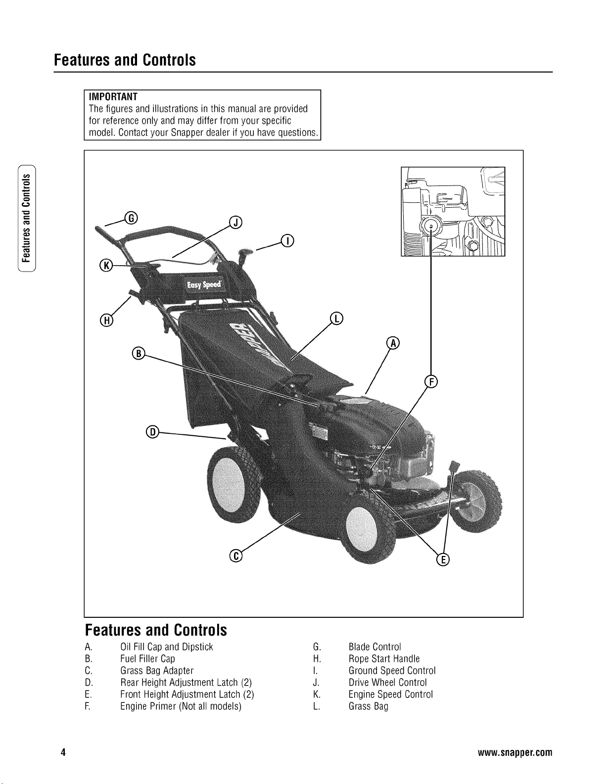
FeaturesandControls
IMPORTANT
The figures and illustrations in this manualare provided
for referenceonly and may differ from your specific
model. Contactyour Snapperdealer if you havequestions.
x,...
0.1
I.I.
®
FeaturesandControls
A.
B.
C.
D.
E.
E
Oil Fill Capand Dipstick
FuelFillerCap
Grass BagAdapter
RearHeight Adjustment Latch (2)
Front Height Adjustment Latch (2)
EnginePrimer (Not all models)
G.
H.
I.
J.
K.
L.
BladeControl
RopeStart Handle
Ground SpeedControl
Drive WheelControl
EngineSpeedControl
Grass Bag
4 www.snapper.com
Operation
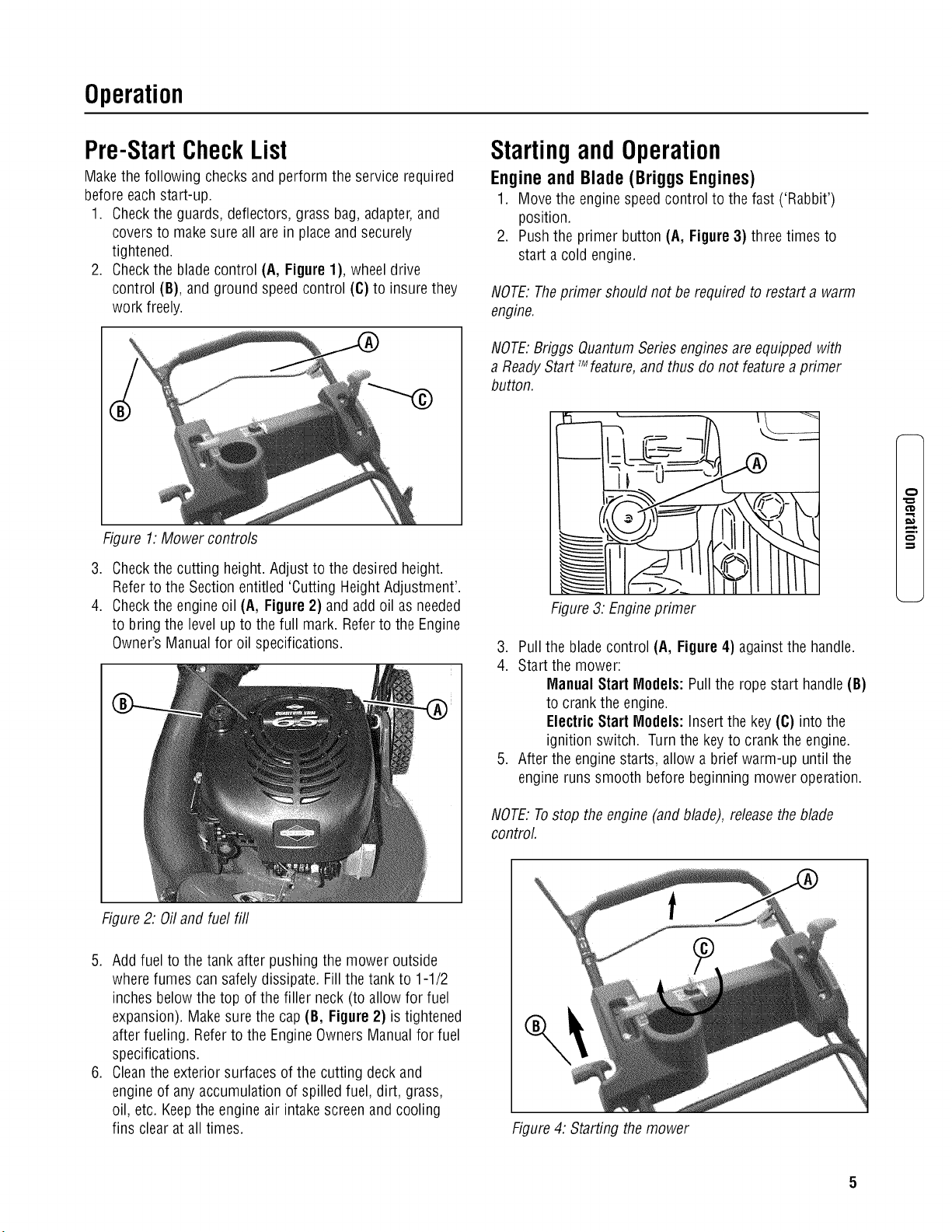
Pre-StartCheckList
Make the following checks and perform the service required
before eachstart-up.
1. Checkthe guards, deflectors, grass bag,adapter,and
covers to makesure all are in placeand securely
tightened.
2. Checkthe blade control (A, Figure 1), wheel drive
control (B), and ground speedcontrol (C) to insurethey
work freely.
StartingandOperation
Engine and Blade (Briggs Engines)
1. Move the engine speedcontrol to the fast ('Rabbit')
position.
2. Pushthe primer button (A, Figure 3) threetimes to
start a cold engine.
NOTE:Theprimer should not be required to restart a warm
engine.
NOTE:Briggs QuantumSeriesenginesare equipped with
a ReadyStart TMfeature,and thus do not feature a primer
button.
Figure 1.Mower controls
3. Checkthe cutting height. Adjust to the desiredheight.
Refer to the Section entitled 'Cutting HeightAdjustment'.
4. Checkthe engineoil (A, Figure 2) and add oil as needed
to bring the level up to the full mark. Referto the Engine
Owner's Manualfor oil specifications.
Figure3: Engineprimer
3. Pullthe blade control (A, Figure 4) against the handle.
4. Startthe mower:
Manual Start Models: Pullthe rope start handle (B)
to crank the engine.
Electric Start Models: Insertthe key(C) into the
ignition switch. Turn the key to crank the engine.
5. Afterthe enginestarts, allow a brief warm-up until the
engine runs smooth before beginning mower operation.
NOTE:Tostop the engine (and blade), releasethe blade
control.
m.
Figure2: Oiland fuel fill
5. Add fuel to the tank after pushing the mower outside
wherefumes cansafely dissipate. Fill thetank to 1-1/2
inches belowthe top of the filler neck(to allow for fuel
expansion). Makesure the cap (B, Figure2) is tightened
after fueling. Referto the EngineOwners Manualfor fuel
specifications.
6. Cleanthe exterior surfaces of the cutting deck and
engine of any accumulation of spilled fuel, dirt, grass,
oil, etc. Keepthe engine air intakescreen and cooling
fins clear at all times.
Figure4: Starting the mower
Operation(Continued)
t::
€:)
,m
o.1
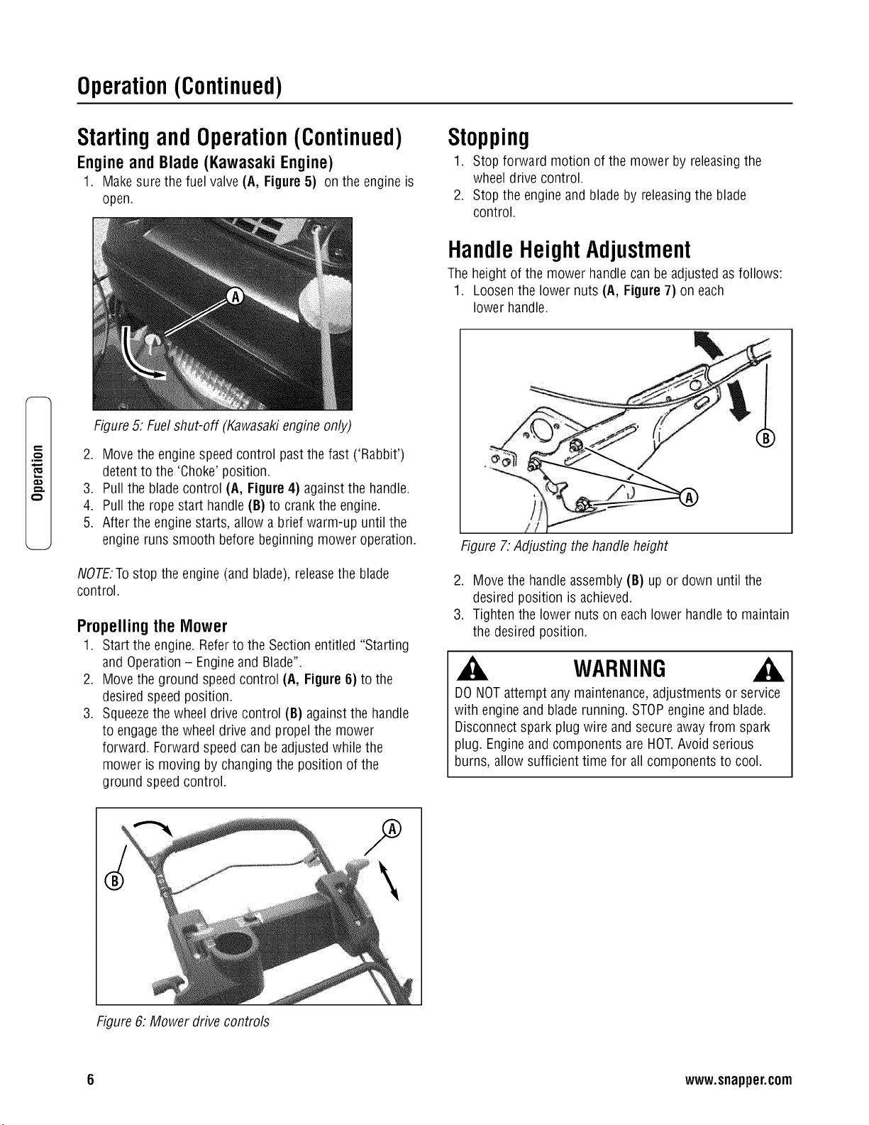
StartingandOperation(Continued)
Engine and Blade (Kawasaki Engine)
1. Make surethe fuel valve (A, Figure5) on the engine is
open.
Figure5. Fuelshut-off (Kawasakiengine only)
2. Move the engine speedcontrol past the fast ('Rabbit')
detent to the 'Choke'position.
3. Pull the blade control (A, Figure4) against the handle.
4. Pull the rope start handle(B) to crank the engine.
5. After the engine starts, allow a brief warm-up until the
engine runs smooth before beginning mower operation.
NOTE.Tostop the engine (and blade), releasethe blade
control.
Propelling the Mower
1. Start the engine. Referto the Section entitled "Starting
and Operation- Engineand Blade".
2. Move the ground speedcontrol (A, Figure6) to the
desired speedposition.
3. Squeezethe wheel drive control (B) againstthe handle
to engagethe wheel drive and propel the mower
forward. Forward speedcan be adjusted while the
mower is moving by changingthe position of the
ground speedcontrol.
1
Stopping
1. Stop forward motion of the mower by releasingthe
wheel drive control.
2. Stop the engine and blade by releasingthe blade
control.
HandleHeightAdjustment
Theheight of the mower handle can be adjusted asfollows:
1. Loosenthe lower nuts (A, Figure7) on each
lower handle.
Figure 7:Adjusting the handleheight
2. Move the handleassembly (B) up or down until the
desired position is achieved.
3. Tighten the lower nuts on eachlower handleto maintain
the desired position.
WARNING
DONOTattempt anymaintenance, adjustmentsor service
with engine and blade running. STOPengine and blade.
Disconnectspark plug wire and secureaway from spark
plug. Engineand components are HOT.Avoid serious
burns, allow sufficient time for all components to cool.
Figure6: Mower drive controls
6 www.snapper.com
Operation(Continued)
WARNING
DONOTattempt any maintenance,adjustments or service
with engine and blade running. STOPengine and blade.
Disconnectspark plug wire and secure away from spark
plug. Engineand components are HOT.Avoid serious
burns, allow sufficient time for all components to cool.
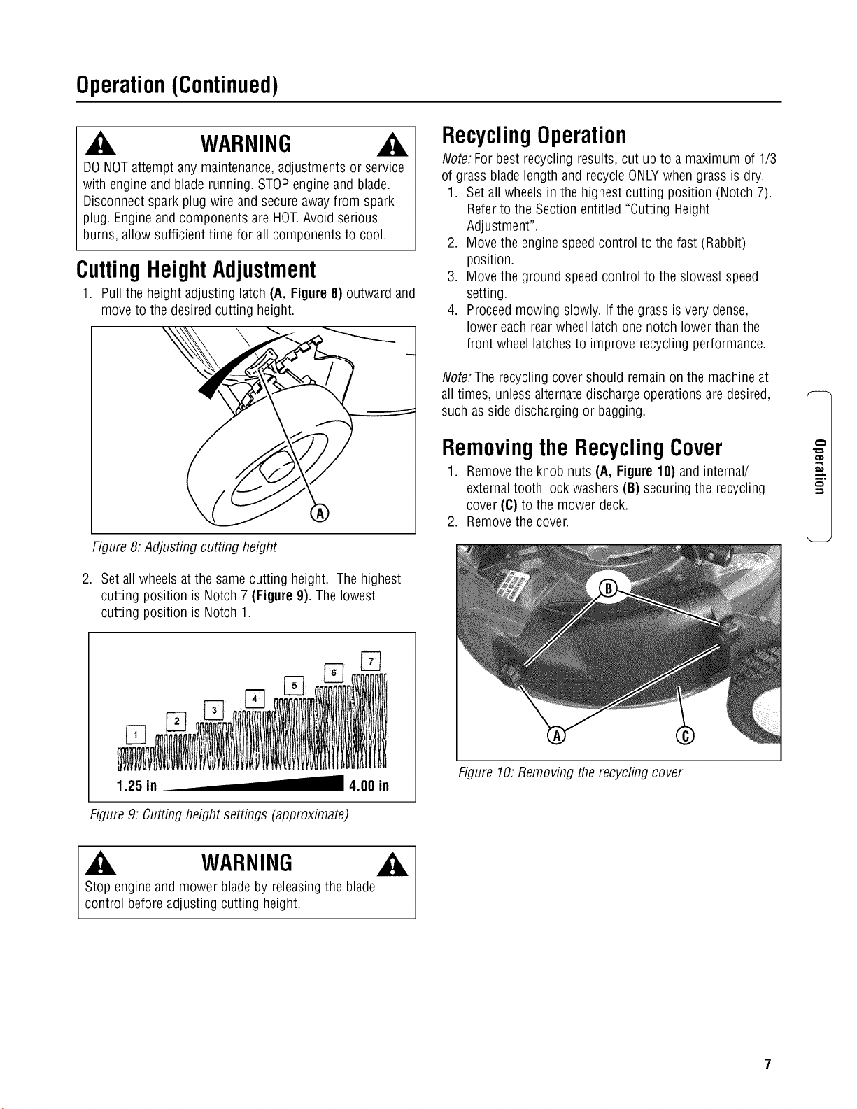
CuttingHeightAdjustment
1. Pull the height adjusting latch (A, Figure8) outward and
move to the desired cutting height.
Figure8:Adjusting cutting height
2. Set all wheels atthe same cutting height. The highest
cutting position is Notch 7 (Figure 9). The lowest
cutting position is Notch 1.
1.25 in 4.00 in
Figure9: Cuttingheight settings (approximate)
RecyclingOperation
Note: Forbest recycling results, cut up to a maximum of 1/3
of grass blade length and recycleONLYwhen grass is dry.
1. Setall wheels in the highest cutting position (Notch 7).
Referto the Sectionentitled "Cutting Height
Adjustment".
2. Move the engine speedcontrol to the fast (Rabbit)
position.
3. Move the ground speed control to the slowest speed
setting.
4. Proceedmowing slowly. If the grass is very dense,
lower each rearwheel latch onenotch lower than the
front wheel latchesto improve recycling performance.
Note:The recycling cover should remain on the machineat
all times, unless alternatedischarge operations are desired,
such asside discharging or bagging.
Removingthe RecyclingCover
1. Removethe knob nuts (A, Figure 10) and internal/
externaltooth lock washers(B) securing the recycling
cover (C) to the mower deck.
2. Removethe cover.
Figure 10. Removingthe recycling cover
m.
WARNING
Stop engineand mower blade by releasingthe blade
control before adjusting cutting height.
Operation(Continued)
t_
,m
WARNING
DONOTattempt any maintenance,adjustments or service
with engine and blade running. STOPengine and blade.
Disconnectspark plug wire and secure away from spark
plug. Engineand components are HOT.Avoid serious
burns, allow sufficient time for all components to cool.
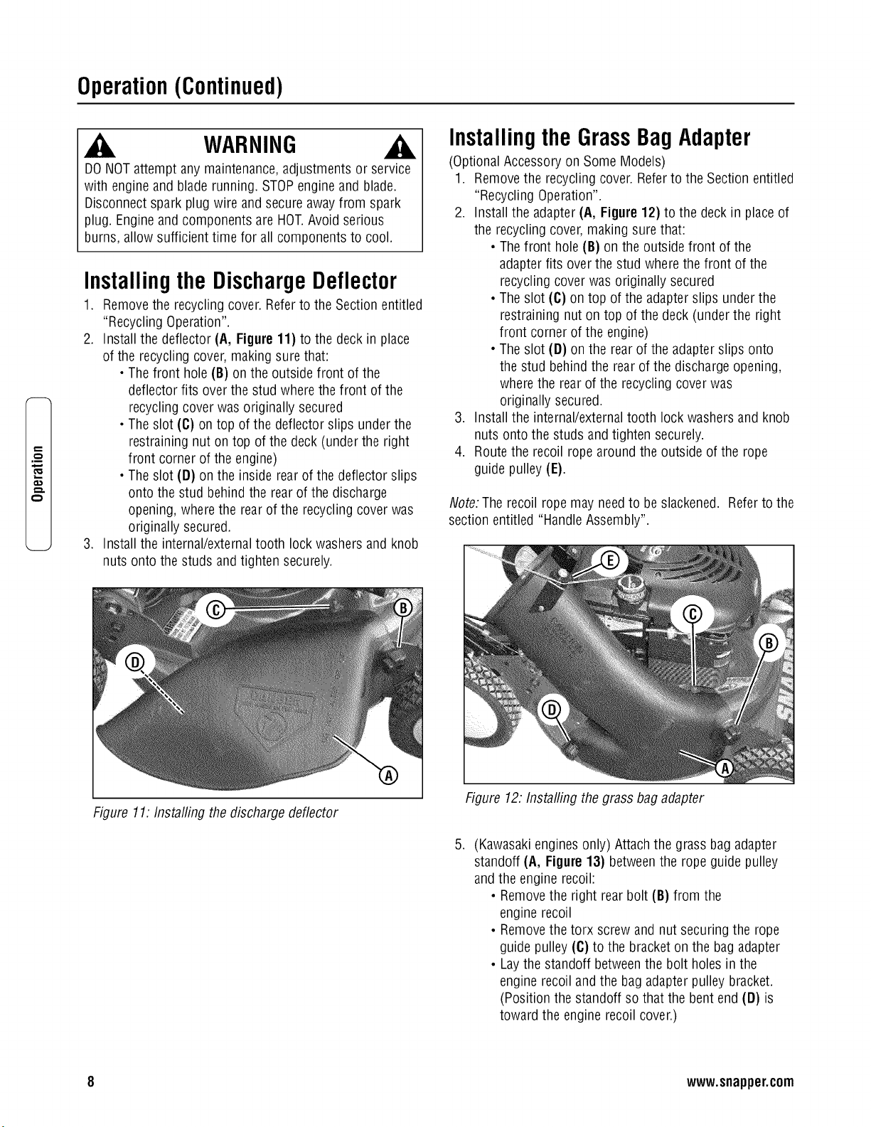
Installingthe DischargeDeflector
1. Removethe recycling cover. Referto the Section entitled
"Recycling Operation".
2. Install the deflector (A, Figure11) to the deck in place
of the recycling cover,making sure that:
• Thefront hole (B) on the outside front of the
deflector fits over the stud wherethe front of the
recycling cover was originally secured
• Theslot (C) on top of the deflector slips underthe
restraining nut on top of the deck (under the right
front corner of the engine)
• Theslot (D) on the inside rear of the deflector slips
onto the stud behind the rear of the discharge
opening, wherethe rear of the recycling cover was
originally secured.
3. Install the internal/externaltooth lock washersand knob
nuts onto the studs andtighten securely.
Figure 11: Installing the discharge deflector
Installingthe GrassBagAdapter
(Optional Accessoryon Some Models)
1. Removethe recycling cover. Referto the Section entitled
"Recycling Operation".
2. Install the adapter(A, Figure 12) to the deck in placeof
the recycling cover, making surethat:
• Thefront hole (B) on the outside front of the
adapterfits over the stud where thefront of the
recycling cover was originally secured
• Theslot (C) on top of the adapterslips under the
restraining nut on top of the deck (under the right
front corner of the engine)
• Theslot (D) on the rear of the adapterslips onto
the stud behind the rear of the discharge opening,
wherethe rear of the recycling cover was
originally secured.
3. Install the internal/externaltooth lock washersand knob
nuts onto the studs and tighten securely.
4. Route the recoil rope around the outside of the rope
guide pulley (E).
Note:The recoil rope may needto be slackened. Referto the
section entitled "HandleAssembly".
.
Figure 12.Installing the grass bag adapter
(Kawasakienginesonly) Attachthe grass bag adapter
standoff (A, Figure13) betweenthe rope guide pulley
and the engine recoil:
• Removethe right rear bolt (B) from the
engine recoil
• Removethe torx screwand nut securing the rope
guide pulley (C)to the bracket on the bagadapter
• Laythe standoff betweenthe bolt holes in the
engine recoil and the bag adapterpulley bracket.
(Position the standoff so that the bent end (D) is
toward the engine recoil cover.)
8 www.snapper.com
Operation(Continued)
WARNING
DONOTattempt any maintenance,adjustments or service
with engine and blade running. STOPengine and blade.
Disconnectspark plug wire and secure away from spark
plug. Engineand components are HOT.Avoid serious
burns, allow sufficient time for all components to cool.
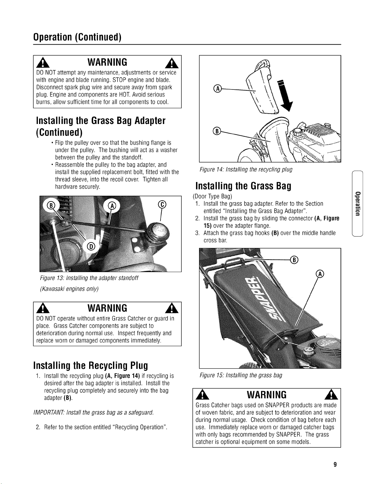
InstallingtheGrassBagAdapter
(Continued)
• Flipthe pulley over sothat the bushing flange is
under the pulley. The bushing will act as a washer
betweenthe pulley and the standoff.
• Reassemblethe pulleyto the bag adapter,and
install the supplied replacementbolt, fitted with the
thread sleeve,into the recoil cover. Tighten all
hardwaresecurely.
Figure 13: Installing theadapterstandoff
(Kawasakienginesonly)
WARNING
DONOToperatewithout entire Grass Catcheror guard in
place. GrassCatchercomponents are subject to
deterioration during normal use. Inspect frequently and
replaceworn or damagedcomponents immediately.
InstallingtheRecyclingPlug
1. Install the recycling plug (A, Figure 14) if recycling is
desired after the bag adapter is installed. Install the
recycling plug completely and securely into the bag
adapter(B).
IMPORTANT.Install thegrass bag as a safeguard.
2. Referto the section entitled "Recycling Operation".
Figure 14.Installing the recycfing plug
InstallingtheGrassBag
(Door Type Bag)
1. Install the grass bag adapter.Refer to the Section
entitled "Installing the Grass BagAdapter".
2. Install the grass bag by sliding the connector (A, Figure
15) over the adapterflange.
3. Attachthe grass bag hooks (B) overthe middle handle
cross bar.
®
Figure 15.Installing thegrass bag
_k WARNING
GrassCatcherbags usedon SNAPPERproducts are made
of woven fabric, and are subject to deterioration and wear
during normal usage. Checkcondition of bag before each
use. Immediately replaceworn or damagedcatcherbags
with only bags recommendedby SNAPPER.The grass
catcher is optional equipment on some models.
m.
Maintenance
p,,
q-.
.m
_E
Maintenance-Introduction
Toretain the quality of the mower,use genuineSNAPPER
replacementparts only. Contact a local SNAPPERdealer for
parts and service assistance.Forthe correct part or
information for a particular mower, always mention the
model and serial number.
WARNING
DONOTattempt any maintenance,adjustments or service
with engine and blade running. STOPengine and blade.
Disconnectspark plug wire and secure away from spark
plug. Engineand components are HOT.Avoid serious
burns, allow sufficient time for all components to cool.
Wearheavy leathergloves when handling or working
around cutting blades. Bladesare extremely sharp and can
causesevere injury.
Service- AfterFirst5 Hours
Change Engine Oil
1. Refer to the EngineManualfor proper oil specifications,
procedures and proper service intervals.
2. Forthe simplest/cleanest oil change,simply turn the
mower on its sideto drain the oil, asshown. Drainthe
oil through the dipstick tube (A, Figure 16) into a
container.Allow sufficient time for all the oil to drain.
Important: Drainthe fuel tank beforetipping the machine.
DONOTtip the machinewith the carburetor or spark plug
down. Oil from the crankcasewill saturatethe air filter and
causethe engineto be hard to start or not start at all. If
contamination doesoccur, the air filter will haveto be
replaced.
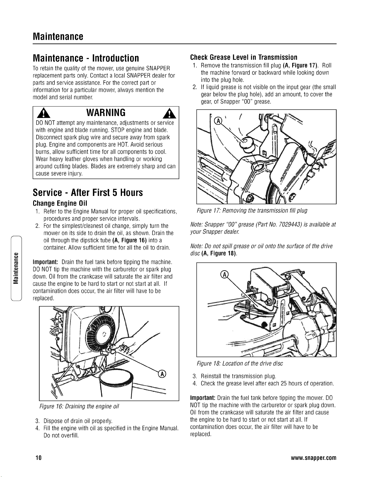
CheckGreaseLevelin Transmission
1. Removethe transmission fill plug (A, Figure 17). Roll
the machine forward or backwardwhile looking down
into the plug hole.
2. If liquid greaseis not visible on the input gear (the small
gear belowthe plug hole), add an amount, to cover the
gear,of Snapper "00" grease.
Figure 17. Removingthe transmission fill plug
Note: Snapper "00" grease(Part No. 7029443) is availableat
your Snapper dealer.
Note: Do not spill greaseor oil onto the surface of the drive
disc (A, Figure18).
%
Figure 16: Draining theengine oil
3. Disposeof drain oil properly.
4. Fillthe enginewith oil as specified in the EngineManual.
Do not overfill.
Figure 18: Location of the drive disc
3. Reinstallthe transmission plug.
4. Checkthe greaselevelafter each 25 hours of operation.
Important:Drain the fuel tank beforetipping the mower. DO
NOTtip the machinewith the carburetor or spark plug down.
Oil from the crankcasewill saturatethe air filter andcause
the engine to be hard to start or not start at all. If
contamination does occur,the air filter will haveto be
replaced.
10 www.snapper.com
Maintenance(Continued)
WARNING
DONOTattempt any maintenance,adjustments or service
with engine and blade running. STOPengine and blade.
Disconnectspark plug wire and secure away from spark
plug. Engineand components are HOT.Avoid serious
burns, allow sufficient time for all components to cool.
Wearheavy leathergloves when handling or working
around cutting blades. Bladesare extremely sharp and can
causesevere injury.
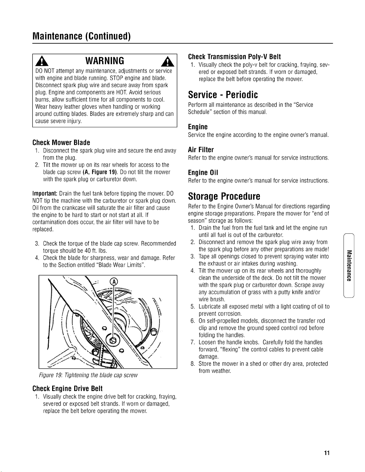
Check Mower Blade
1. Disconnectthe spark plug wire and securethe end away
from the plug.
2. Tilt the mower up on its rearwheels for accessto the
blade cap screw(A, Figure19). Do not tilt the mower
with the spark plug or carburetor down.
Important:Drainthe fuel tank beforetipping the mower. DO
NOTtip the machine with the carburetor or spark plug down.
Oil from the crankcasewill saturatethe air filter and cause
the engineto be hard to start or not start at all. If
contamination doesoccur, the air filter will haveto be
replaced.
3. Checkthe torque of the bladecap screw. Recommended
torque should be 40 ft. Ibs.
4. Checkthe bladefor sharpness, wear and damage. Refer
to the Section entitled "BladeWear Limits".
Figure 19. Tightening the blade capscrew
Check Engine Drive Belt
1. Visually check the enginedrive belt for cracking, fraying,
severedor exposed belt strands. If worn or damaged,
replacethe belt before operating the mower.
Check Transmission Poly-V Belt
1. Visually checkthe poly-v belt for cracking, fraying, sev-
ered or exposed belt strands. If worn or damaged,
replacethe belt before operating the mower.
Service- Periodic
Perform all maintenanceas described in the "Service
Schedule" section of this manual.
Engine
Service the engine according to the engineowner's manual.
Air Filter
Referto the engine owner's manualfor service instructions.
EngineOil
Referto the engine owner's manualfor service instructions.
StorageProcedure
Referto the EngineOwner'sManual for directions regarding
engine storage preparations. Preparethe mower for "end of
season"storage asfollows:
1. Drainthe fuel from the fuel tank and letthe engine run
until all fuel is out of the carburetor.
2. Disconnect and remove the spark plug wire awayfrom
the spark plug beforeany other preparations are made!
3. Tapeall openingsclosed to preventspraying water into
the exhaustor air intakes during washing.
4. Tilt the mower up on its rear wheels and thoroughly
cleanthe undersideof the deck. Do not tilt the mower
with the spark plug or carburetor down. Scrapeaway
any accumulation of grass with a putty knife and/or
wire brush.
5. Lubricate all exposed metal with a light coating of oil to
prevent corrosion.
6. On self-propelled models, disconnect the transfer rod
clip and remove the ground speedcontrol rod before
folding the handles.
7. Loosenthe handle knobs. Carefullyfold the handles
forward, "flexing" the control cablesto prevent cable
damage.
8. Store the mower in a shed or other dry area,protected
from weather.
m.
€'D
11
Maintenance(Continued)
,m
_E
WARNING
DONOTattempt any maintenance,adjustments or service
with engine and blade running. STOPengine and blade.
Disconnectspark plug wire and secure away from spark
plug. Engineand components are HOT.Avoid serious
burns, allow sufficient time for all components to cool.
Wearheavy leathergloves when handling or working
around cutting blades. Bladesare extremely sharp and can
causesevere injury.
MowerBladeReplacement
Standard Blade Wear Limit
1. Inspect the blade(Figure20) frequently for signs of
excessivewear or damage:
(A) New blade
(B) Wearlimit (notch starts)
(C) Dangerous condition! Do not useon the mower!
Replacewith a newblade.
Figure20: Standardblade wearlimits
Ninja Blade Wear Limit
1. Inspect the blade(Figure21) frequently for signs of
excessivewear or damage:
(A) New blade
(B) Wearlimit (cracks or notches beginto appearon
tip)
(C) Dangerous condition! Do not useon the mower!
Replacewith a newblade.
WARNING
DONOTuse a cutting bladethat shows signs of excessive
wear or damage.Refer to the Section entitled "MOWER
BLADEREPLACEMENT"for proper blade inspection and
service procedures.
Figure21: Ninjablade wearfimits
BladeSharpening
1. Disconnectthe spark plug wire and secure the end away
from the plug.
2. Tilt the mower up on its rear wheels. Donot tilt the
mower with the spark plug or carburetor down.
Important:Drain the fueltank beforetipping the mower. DO
NOTtip the machinewith the carburetor or spark plug down.
Oil from the crankcasewill saturatethe air filter andcause
the engineto be hard to start or not start at all. If
contamination does occur,the air filter will haveto be
replaced.
3. Removethe blade (B, Figure22).
Makesure that
bladehub is seatedI
[betweenfanges J
i
Figure22: Removingthe mower blade
12 www.snapper.com
Maintenance(Continued)
WARNING
DONOTattempt any maintenance,adjustments or service
with engine and blade running. STOPengineand blade.
Disconnectspark plug wire and secure awayfrom spark
plug. Engineand components are HOT.Avoid serious
burns, allow sufficient time for all components to cool.
BladeSharpening(Continued)
4. Sharpenthe bladeon a grinding wheelat an angle of 22
to 28 degrees(B, Figure 23). DONOTsharpen the blade
beyondthe original cutting edge(A).
Do not sharpen
beyondoriginal
cutting edge
Endview of
bladeassembly
Figure23: Sharpening themower blade
5. Checkbladefor balance.If necessary,correct balanceby
grinding heavyend of blade.
6. Reinstall blade(B, Figure 22}. Notethe correct
assembly order:
(A) Blade hub
(B) Blade
(C) Bladeflange (facing up)
(D) Conewasher (concaveside up)
(E) Capscrew
7. Checktorque of blade retainingcap screw.
Recommendedtorque should be 40 ft. Ibs.
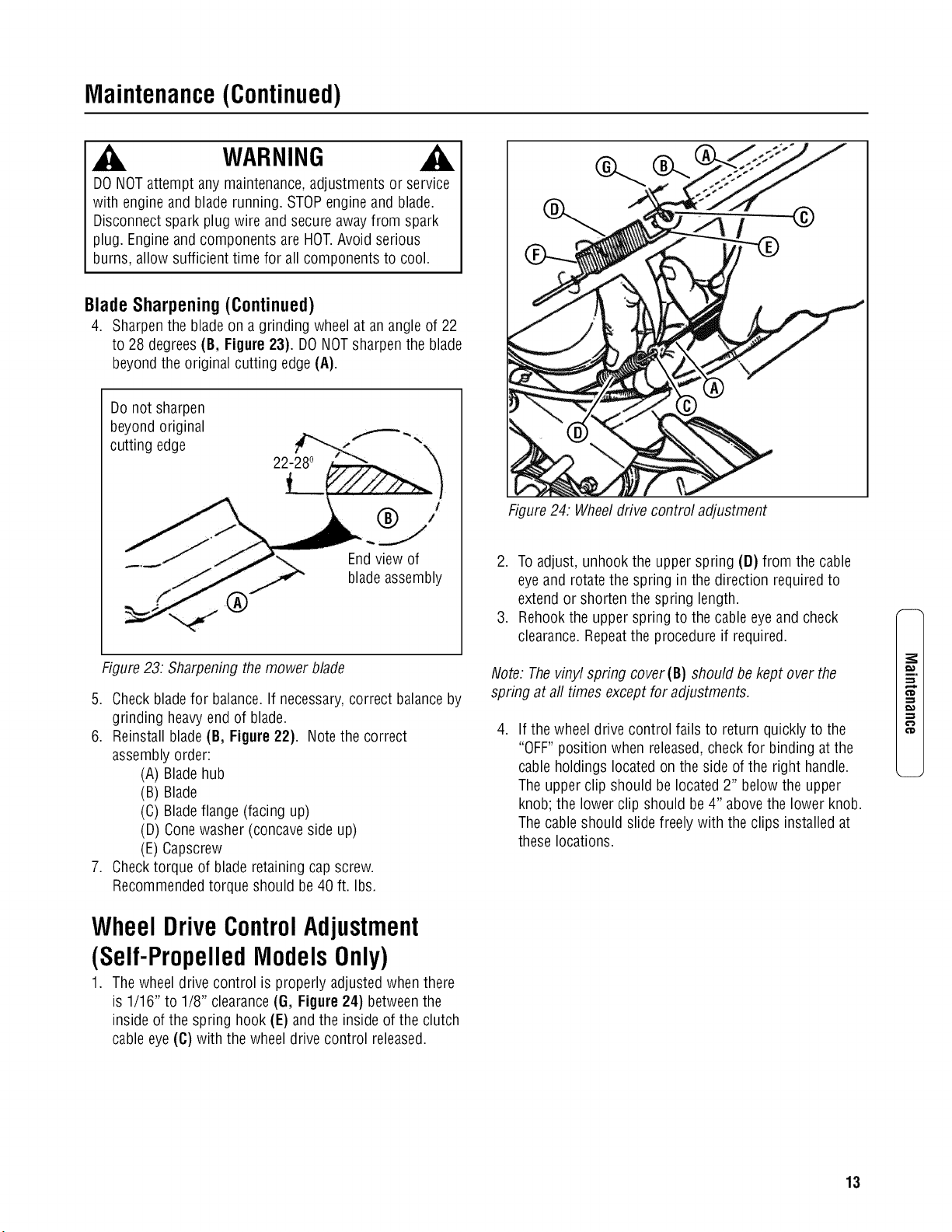
WheelDriveControlAdjustment
(Self-PropelledModelsOnly)
1. Thewheel drive control is properly adjusted when there
is 1/16" to 1/8" clearance(G, Figure24) betweenthe
inside of the spring hook (E) and the inside of the clutch
cableeye(C) with the wheeldrive control released.
Figure24: Wheeldrive control adjustment
2. Toadjust, unhook the upper spring (D) from the cable
eyeand rotatethe spring in the direction required to
extend or shorten the spring length.
3. Rehook the upper spring to the cable eyeand check
clearance.Repeatthe procedure if required.
Note. Thevinyl spring cover(B) should be kept over the
spring at aft times except for adjustments.
.
If the wheel drive control fails to return quickly to the
"OFF"position when released,checkfor binding at the
cable holdings located on the side ofthe right handle.
Theupper clip should be located 2" below the upper
knob; the lower clip should be 4" abovethe lower knob.
Thecableshould slide freely with the clips installed at
these locations.
m.
€'D
13
Maintenance(Continued)
e,,,
t_
.m
_E
WARNING
DONOTattempt any maintenance,adjustments or service
with engine and blade running. STOPengineand blade.
Disconnectspark plug wire and secure awayfrom spark
plug. Engineand components are HOT.Avoid serious
burns, allow sufficient time for all components to cool.
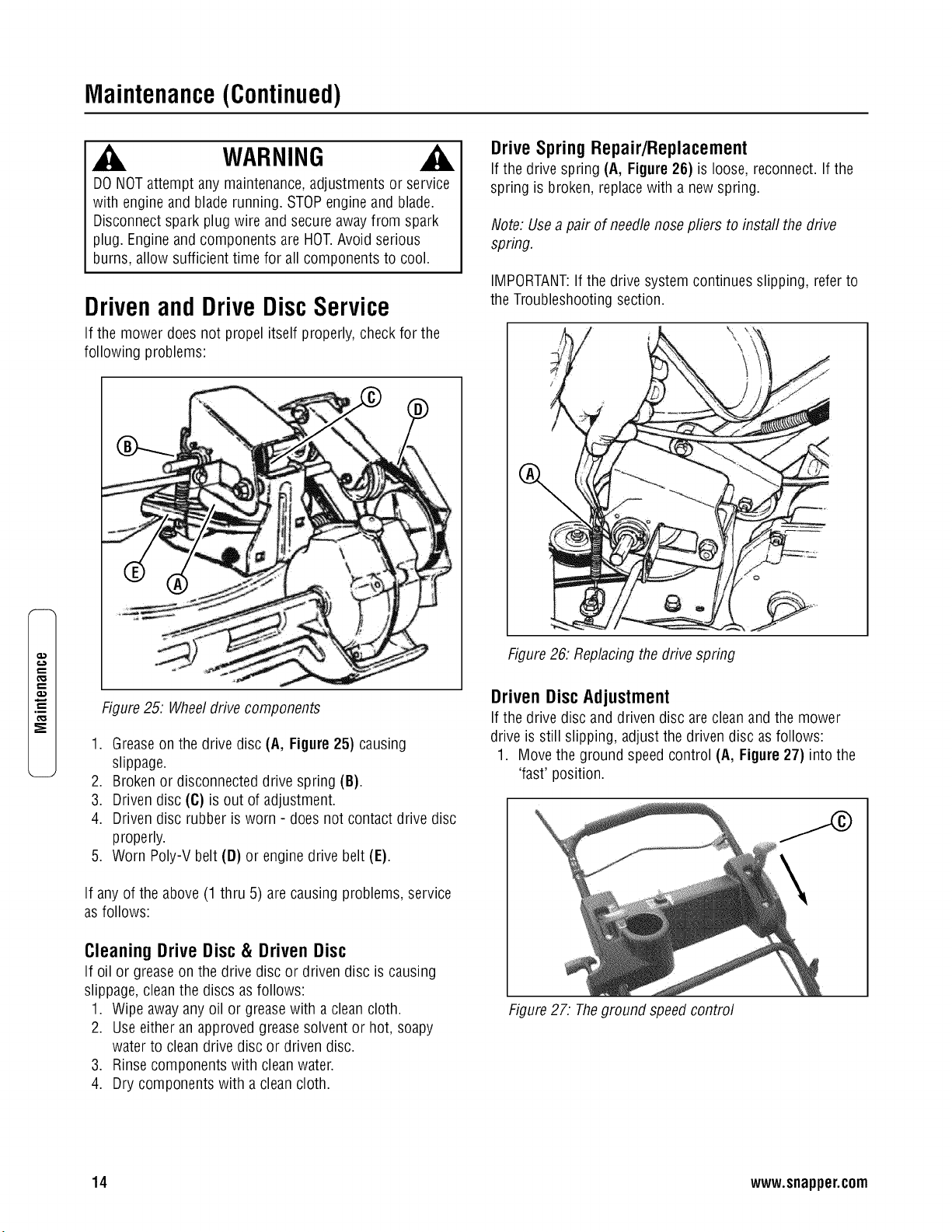
DrivenandDriveDiscService
If the mower does not propel itself properly, check for the
following problems:
Figure25. Wheeldrive components
1. Greaseon the drive disc (A, Figure 25) causing
slippage.
2. Brokenor disconnecteddrive spring (B).
3. Driven disc (C) is out of adjustment.
4. Driven disc rubber is worn - does not contact drive disc
properly.
5. Worn Poly-Vbelt (D) or engine drive belt (E).
If any of the above (1 thru 5) arecausing problems, service
asfollows:
Cleaning Drive Disc & Driven Disc
If oil or greaseon the drive disc or driven disc is causing
slippage, cleanthe discs asfollows:
1. Wipe awayany oil or greasewith a cleancloth.
2. Use either an approvedgreasesolvent or hot, soapy
water to cleandrive disc or driven disc.
3. Rinse components with cleanwater.
4. Dry components with a cleancloth.
DriveSpringRepair/Replacement
If the drive spring (A, Figure 26) is loose, reconnect. If the
spring is broken, replacewith a newspring.
Note: Usea pair of needlenose pliers to install the drive
spring.
IMPORTANT:If the drive system continues slipping, referto
the Troubleshootingsection.
Figure26: Replacingthe drive spring
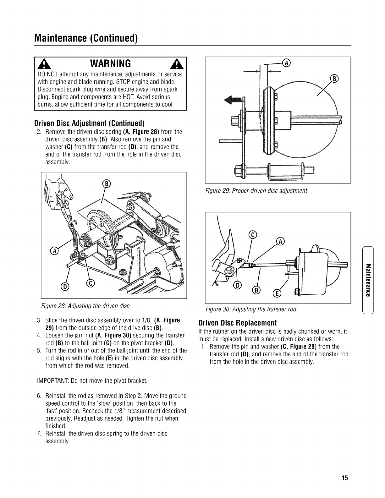
Driven DiscAdjustment
If the drive disc and driven disc areclean and the mower
drive is still slipping, adjust the driven disc asfollows:
1. Move the ground speed control (A, Figure27) into the
'fast' position.
Figure27: Theground speed control
14 www.snapper.com
Maintenance(Continued)
WARNING
DONOTattempt any maintenance,adjustments or service
with engine and blade running. STOPengineand blade.
Disconnectspark plug wire and secure awayfrom spark
plug. Engineand components are HOT.Avoid serious
burns, allow sufficient time for all components to cool.
Driven Disc Adjustment (Continued)
2. Removethe driven disc spring (A, Figure 28) from the
driven disc assembly (B). Also removethe pin and
washer (C) from the transfer rod (D), and removethe
end of the transfer rod from the hole in the driven disc
assembly.
Figure28: Adjusting the driven disc
3. Slide the driven disc assembly over to 1/8" (A, Figure
29) from the outside edge of the drive disc (B).
4. Loosenthe jam nut (A, Figure 38) securing the transfer
rod (B) to the ball joint (C) on the pivot bracket (D).
5. Turnthe rod in or out of the ball joint until the end of the
rod aligns with the hole (E) in the driven disc assembly
from which the rod was removed.
IMPORTANT:Donot move the pivot bracket.
6. Reinstallthe rod as removed in Step 2. Move the ground
speedcontrol to the 'slow' position, then backto the
'fast' position. Recheckthe 1/8" measurement described
previously. Readjustas needed.Tighten the nut when
finished.
7. Reinstallthe driven disc spring to the driven disc
assembly.
Figure29: Proper driven disc adjustment
Figure30: Adjusting the transfer rod
Driven Disc Replacement
If the rubber on the driven disc is badly chunked or worn, it
must be replaced. Install a newdriven disc asfollows:
1. Removethe pin and washer (C, Figure 28) from the
transfer rod (D), and removethe end of the transfer rod
from the hole in the driven disc assembly.
m.
15
Maintenance(Continued)
e,,,
t_
.m
_E
WARNING
DONOTattempt any maintenance,adjustments or service
with engine and blade running. STOPengineand blade.
Disconnectspark plug wire and secure awayfrom spark
plug. Engineand components are HOT.Avoid serious
burns, allow sufficient time for all components to cool.
Driven Disc Replacement (Continued)
2. Using needlenose pliers, unhook the drive spring (A,
Figure 31) and slide the driven disc assembly off the
hex shaft.
3. Removethe two snap rings (A, Figure 32) which secure
the rubber driven disc (B) to the driven disc assembly.
4. Install a new rubber driven disc onto the driven disc
assembly,and secure with the retaining rings.
5. Reversethe above proceduresfor reassemblyand
installation ofthe driven disc assembly.
Figure31. Removingthe driven disc assembly
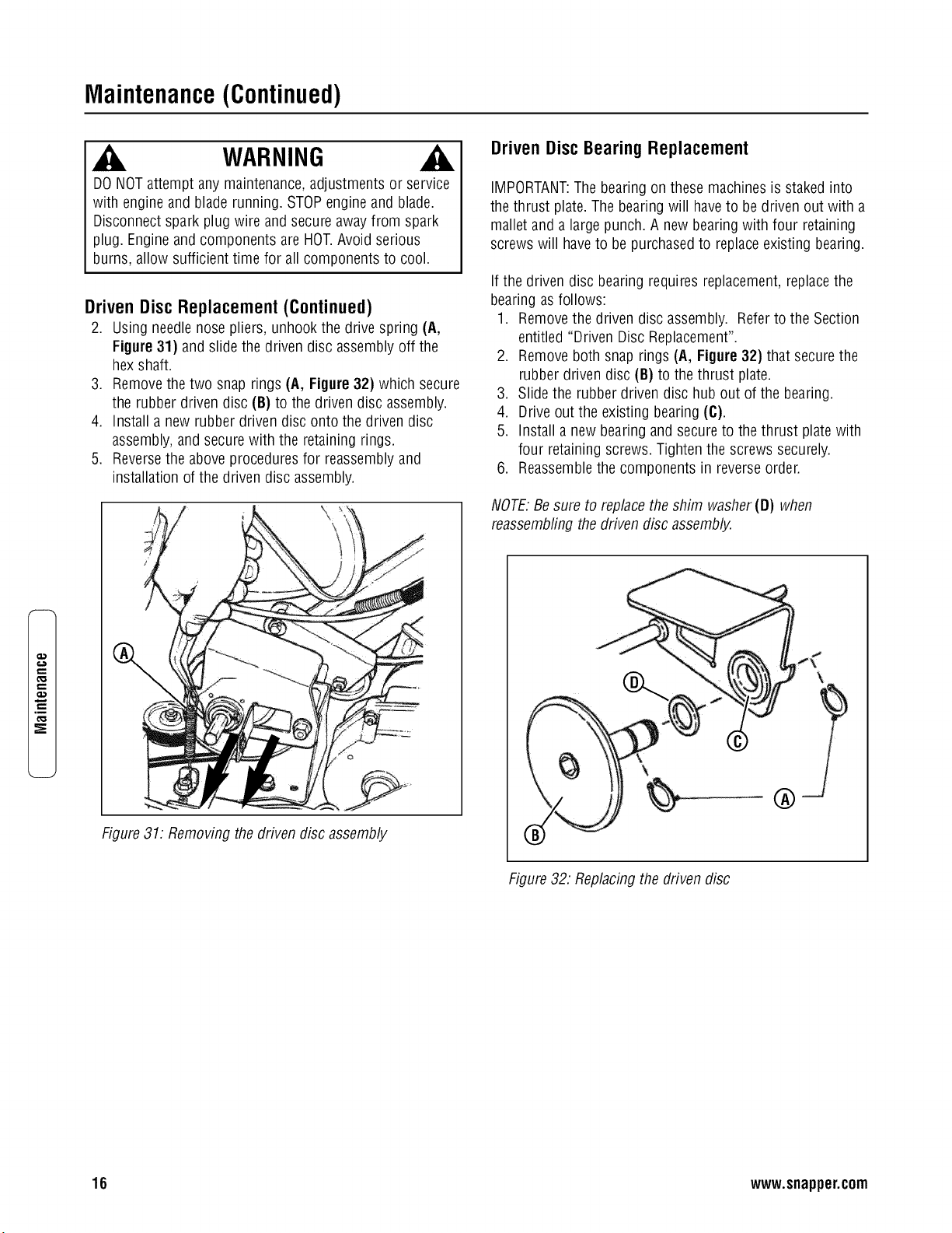
Driven Disc Bearing Replacement
IMPORTANT:Thebearing on these machinesis stakedinto
the thrust plate. The bearingwill haveto be driven out with a
mallet and a large punch. A new bearing with four retaining
screws will haveto be purchasedto replaceexisting bearing.
If the driven disc bearing requires replacement,replacethe
bearing as follows:
1. Removethe driven disc assembly. Referto the Section
entitled "Driven Disc Replacement".
2. Removeboth snap rings (A, Figure 32) that secure the
rubber driven disc (B) to the thrust plate.
3. Slide the rubber driven disc hub out of the bearing.
4. Drive out the existing bearing (C).
5. Install a new bearing and secure to the thrust platewith
four retaining screws. Tighten the screws securely.
6. Reassemblethe components in reverseorder.
NOTE:Besure to replacethe shim washer(D) when
reassembfingthe driven disc assembly.
®
Figure32. Replacing the driven disc
16 www.snapper.com
Maintenance(Continued)
WARNING
DONOTattempt any maintenance,adjustments or service
with engine and blade running. STOPengineand blade.
Disconnectspark plug wire and secure awayfrom spark
plug. Engineand components are HOT.Avoid serious
burns, allow sufficient time for all components to cool.
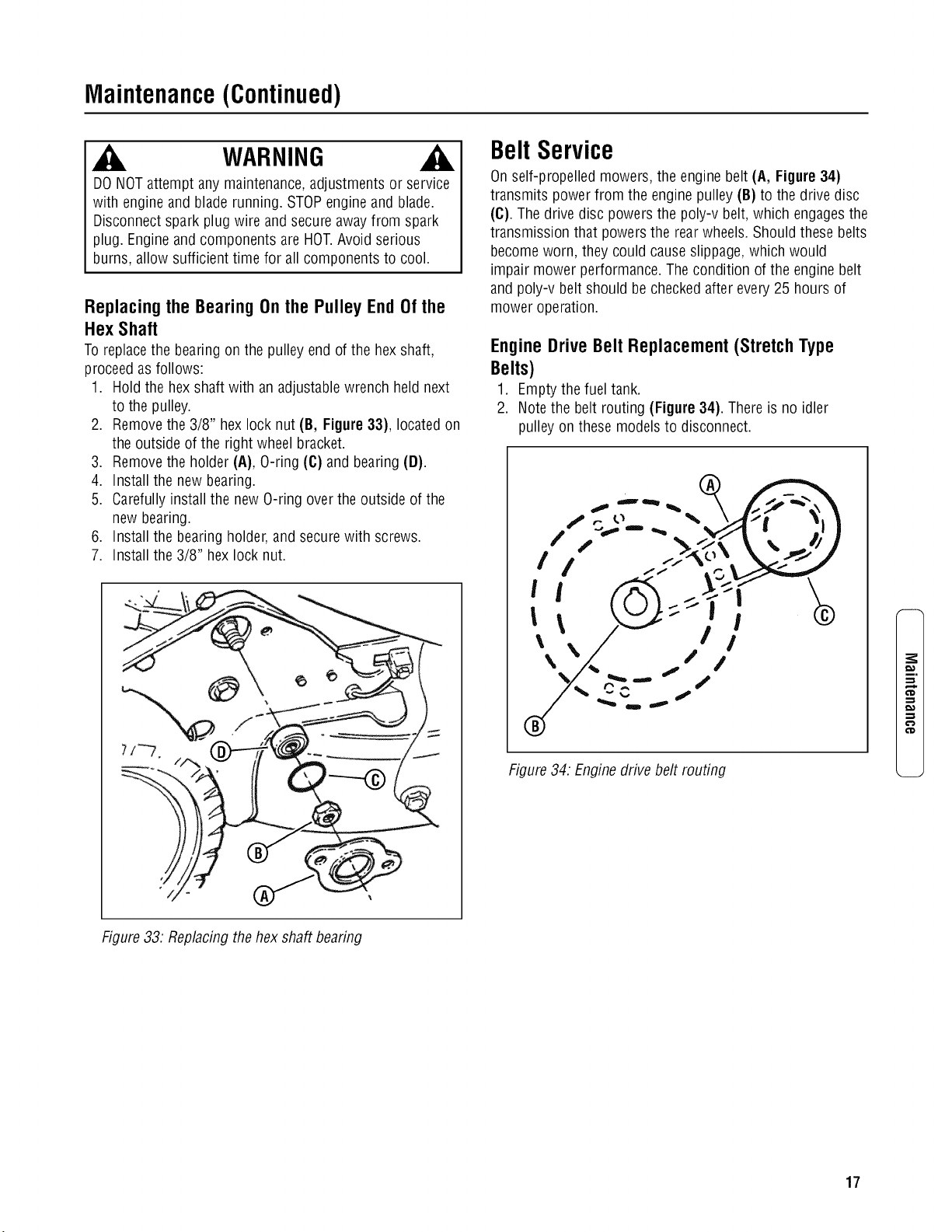
Replacing the Bearing On the Pulley End Of the
Hex Shaft
Toreplacethe bearing on the pulley end of the hexshaft,
proceedas follows:
1. Hold the hex shaft with an adjustablewrench held next
to the pulley.
2. Removethe 3/8" hexlock nut (B, Figure33), located on
the outside of the right wheel bracket.
3. Removethe holder (A), O-ring (C) and bearing (D).
4. Install the new bearing.
5. Carefullyinstall the new O-ring overthe outside of the
new bearing.
6. Install the bearing holder,and secure with screws.
7. Install the 3/8" hex lock nut.
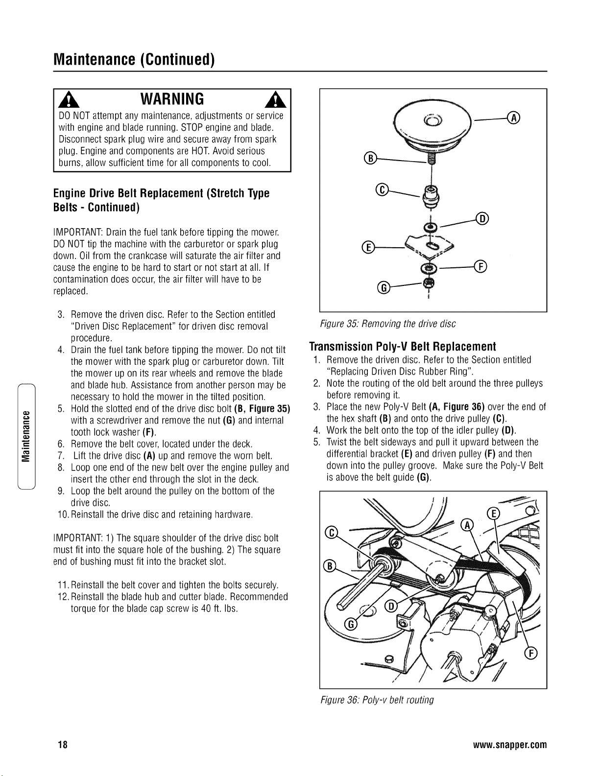
BeltService
On self-propelled mowers, the engine belt (A, Figure 34)
transmits power from the engine pulley (B) to the drive disc
(C). The drive disc powers the poly-v belt, which engagesthe
transmission that powers the rearwheels. Should these belts
become worn, they could cause slippage,which would
impair mower performance. Thecondition of the engine belt
and poly-v belt should be checkedafter every 25 hours of
mower operation.
Engine Drive Belt Replacement (Stretch Type
Belts)
1. Emptythe fuel tank.
2. Note the belt routing (Figure 34). Thereis no idler
pulley on these models to disconnect.
f ,.. o "_ \//>_ "l,
\% \/ /I//
Figure34. Engine drive belt routing
i.
€'D
€'D
Figure33. Replacingthe hex shaft bearing
17
Maintenance(Continued)
e,,,
t_
.m
_E
WARNING
DONOTattempt any maintenance,adjustments or service
with engine and blade running. STOPengineand blade.
Disconnectspark plug wire and secure awayfrom spark
plug. Engineand components are HOT.Avoid serious
burns, allow sufficient time for all components to cool.
EngineDriveBelt Replacement(StretchType
Belts- Continued)
IMPORTANT:Drainthe fuel tank beforetipping the mower.
DONOTtip the machinewith the carburetor or spark plug
down. Oil from the crankcasewill saturatethe air filter and
causethe engineto be hard to start or not start at all. If
contamination doesoccur, the air filter will haveto be
replaced.
3. Removethe driven disc. Referto the Section entitled
"Driven Disc Replacement"for driven disc removal
procedure.
4. Drain the fueltank beforetipping the mower. Do not tilt
the mower with the spark plug or carburetor down. Tilt
the mower up on its rear wheels and removethe blade
and bladehub. Assistancefrom another person may be
necessaryto hold the mower in the tilted position.
5. Hold the slotted end of the drive disc bolt (B, Figure 35)
with a screwdriver and remove the nut (G) and internal
tooth lock washer (F).
6. Removethe belt cover, located under the deck.
7. Lift the drive disc (A) up and removethe worn belt.
8. Loop one end of the new belt overthe engine pulley and
insert the other end through the slot inthe deck.
9. Loop the belt around the pulleyon the bottom of the
drive disc.
10.Reinstallthe drive disc and retaining hardware.
IMPORTANT:1) Thesquareshoulder of the drive disc bolt
must fit into the square holeof the bushing. 2) Thesquare
end of bushing must fit into the bracket slot.
11.Reinstallthe belt cover and tighten the bolts securely.
12.Reinstallthe blade hub and cutter blade. Recommended
torque for the blade cap screw is 40 ft. Ibs.
------4b
)
Figure35. Removingthe drive disc
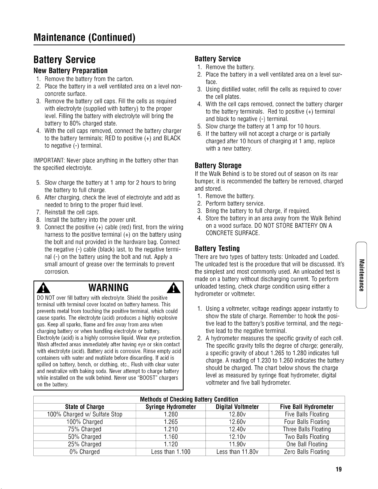
Transmission Poly-V Belt Replacement
1. Removethe driven disc. Referto the Section entitled
"Replacing Driven Disc Rubber Ring".
2. Note the routing of the old belt around the three pulleys
before removing it.
3. Placethe new Poly-V Belt(A, Figure36) over the end of
the hex shaft (B) and onto the drive pulley (C).
4. Work the belt onto the top of the idler pulley(D).
5. Twist the belt sideways and pull it upward betweenthe
differential bracket(E) and driven pulley (F) and then
down into the pulley groove. Makesure the Poly-V Belt
is abovethe belt guide (G).
J
Figure36. Poly-v belt routing
18 www.snapper.com
Maintenance(Continued)
BatteryService
New BatteryPreparation
1. Removethe battery from the carton.
2. Placethe battery in a well ventilated areaon a levelnon-
concrete surface.
3. Removethe battery cell caps. Fillthe cells as required
with electrolyte (supplied with battery) to the proper
level. Fillingthe battery with electrolyte will bring the
battery to 80% chargedstate.
4. With the cell caps removed,connectthe battery charger
to the batteryterminals; REDto positive (+) and BLACK
to negative(-) terminal.
IMPORTANT:Neverplaceanything in the battery other than
the specified electrolyte.
5. Slow chargethe battery at 1 amp for 2 hours to bring
the battery to full charge.
6. After charging, check the levelof electrolyte and add as
neededto bring to the proper fluid level.
7. Reinstallthe cell caps.
8. Install the battery into the power unit.
9. Connectthe positive (+) cable(red) first, from the wiring
harness to the positiveterminal (+) on the battery using
the bolt and nut provided in the hardwarebag. Connect
the negative (-) cable (black) last,to the negativetermi-
nal (-) on the battery using the bolt and nut. Apply a
small amount of greaseover the terminals to prevent
corrosion.
WARNING
DONOToverfill batterywithelectrolyte.Shieldthepositive
terminalwithterminalcoverlocatedonbatteryharness.This
preventsmetalfromtouchingthepositiveterminal,whichcould
causesparks.Theelectrolyte(acid)producesa highlyexplosive
gas.Keepall sparks,flameandfireawayfromareawhen
chargingbatteryor whenhandlingelectrolyteor battery.
Electrolyte(acid)isa highlycorrosiveliquid.Weareyeprotection.
Washaffectedareasimmediatelyafterhavingeyeor skincontact
with electrolyte(acid).Batteryacidiscorrosive.Rinseemptyacid
containerswithwaterandmutilatebeforediscarding.Ifacidis
spilledon battery,bench,or clothing,etc.,Flushwith clearwater
andneutralizewith bakingsoda.Neverattemptto chargebattery
whileinstalledonthewalkbehind.Neveruse"BOOST"chargers
onthebattery.
BatteryService
1. Removethe battery.
2. Placethe battery in a well ventilated areaon a level sur-
face.
3. Using distilled water, refill the cells as requiredto cover
the cell plates.
4. With the cell caps removed,connectthe battery charger
to the batteryterminals. Redto positive (+) terminal
and black to negative (-) terminal.
5. Slow chargethe battery at 1 amp for 10 hours.
6. If the battery will not accepta charge or is partially
chargedafter 10 hours of charging at 1 amp, replace
with a new battery.
BatteryStorage
If the Walk Behindis to be stored out of season on its rear
bumper, it is recommendedthe battery be removed,charged
and stored.
1. Removethe battery.
2. Perform battery service.
3. Bring the battery to full charge, if required.
4. Storethe battery in an area awayfrom the Walk Behind
on a wood surface. DONOTSTOREBATTERYONA
CONCRETESURFACE.
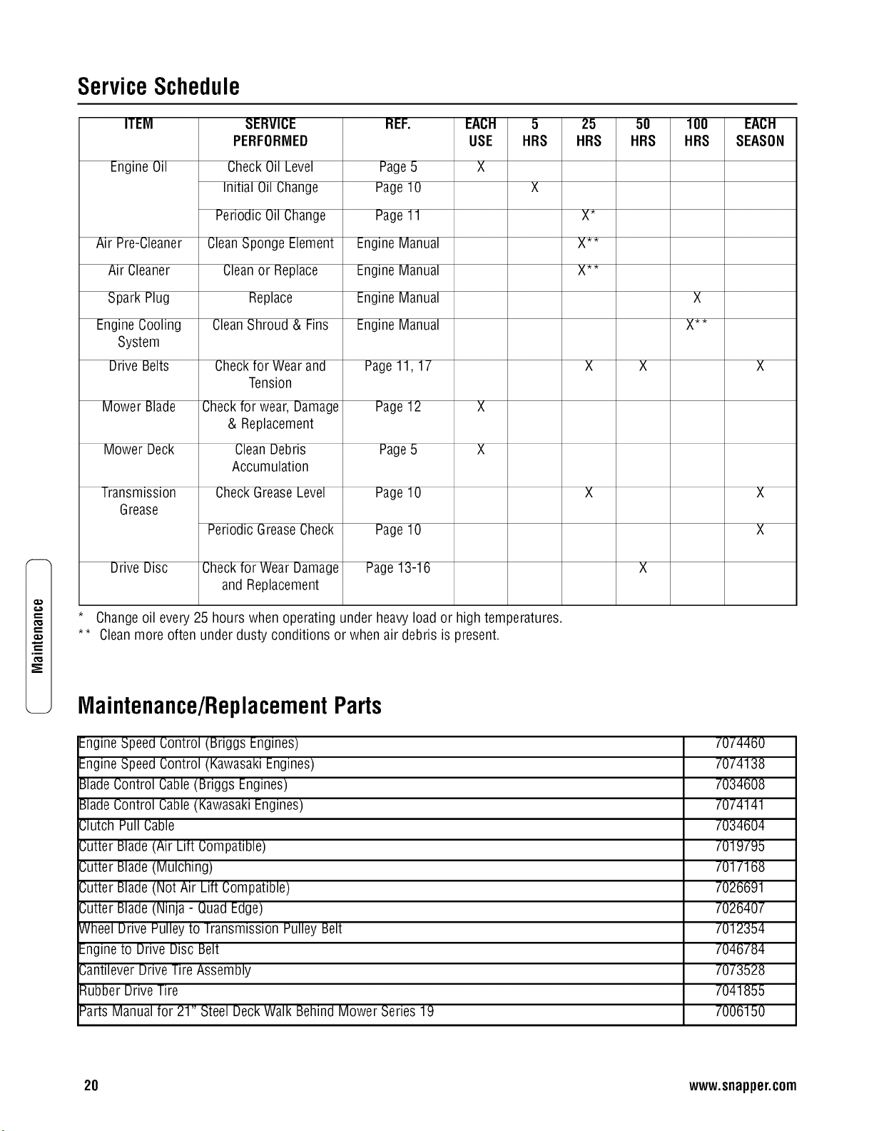
Battery Testing
Thereare two types of batterytests: Unloadedand Loaded.
Theunloaded test isthe procedurethat will be discussed. It's
the simplest and most commonly used. An unloadedtest is
madeon a batterywithout dischargingcurrent. Toperform
unloaded testing, checkcharge condition using either a
hydrometer or voltmeter.
.
.
Using a voltmeter,voltage readingsappear instantly to
show the stateof charge. Rememberto hookthe posi-
tive leadto the battery's positiveterminal, and the nega-
tive leadto the negativeterminal.
A hydrometer measuresthe specific gravity of eachcell.
Thespecific gravity tells the degreeof charge; generally,
a specific gravity of about 1.265 to 1.280 indicatesfull
charge. A readingof 1.230 to 1.260 indicatesthe battery
should be charged.The chart belowshows the charge
level asmeasured by syringe float hydrometer,digital
voltmeter and five ball hydrometer.
Methodsof CheckingBatteryCondition
State of Charge SyringeHydrometer Digital Voltmeter Five BallHydrometer
100% Chargedw/Sulfate Stop 1.280 12.80v FiveBallsFloating
100% Charged 1.265 12.60v Four Balls Floating
75% Charged 1.210 12.40v ThreeBalls Floating
50% Charged 1.160 12.10v Two Balls Floating
25% Charged 1.120 11.90v One Ball Floating
0% Charged Lessthan 1.100 Lessthan 11.80v Zero Balls Floating
m,
¢D
€'D
19
,m
ServiceSchedule
ITEM
Engine Oil
Air Pre-Cleaner
Air Cleaner
Spark Plug
EngineCooling
System
Drive Belts
Mower Blade
Mower Deck
Transmission
Grease
Drive Disc
SERVICE
PERFORMED
CheckOil Level
Initial Oil Change
Periodic Oil Change
CleanSponge Element
Cleanor Replace
Replace
CleanShroud & Fins
Checktor Wearand
Tension
Checkfor wear, Damage
& Replacement
CleanDebris
Accumulation
CheckGreaseLevel
Periodic GreaseCheck
Checkfor WearDamage
and Replacement
REF.
Page5
Page10
Page11
EngineManual
EngineManual
EngineManual
EngineManual
EACH
USE
5
HRS
X
Page11, 17
Page12 X
Page5 X
Page10
Page10
Page13-16
* Changeoil every 25 hours when operating under heavyload or high temperatures.
** Cleanmore often under dusty conditions or when air debris is present.
25
HRS
X_
X**
X**
5O
HRS
lOO
HRS
X
X**
Maintenance/ReplacementParts
EngineSpeed Control (Briggs Engines)
EngineSpeed Control (KawasakiEngines)
BladeControl Cable(Briggs Engines)
BladeControl Cable(KawasakiEngines)
Clutch Pull Cable
Cutter Blade(Air Lift Compatible)
Cutter Blade(Mulching)
Cutter Blade(Not Air Lift Compatible)
Cutter Blade(Ninja - Quad Edge)
Wheel Drive Pulleyto Transmission Pulley Belt
Engineto Drive Disc Belt
CantileverDrive TireAssembly
Rubber Drive Tire
Parts Manual for 21" Steel DeckWalk Behind Mower Series19
EACH
SEASON
X
X
X
7074460
7074138
7034608
7074141
7034604
7019795
7017168
7026691
7026407
7012354
7046784
7073528
7041855
7006150
20 www.snapper.com
Troubleshooting
PROBLEM
EngineWill Not Start Using
Recoil Starter
EngineWill Not Start (Electri(
Start Models)
EngineStalls or Stops After
Running
EngineLoses Power
Excessive Vibration
IVlowerWill Not IVloveLoss
OfTraction (Self-Propelled
Models)
Cutting GrassImproperly
Poor Grass Discharge
Oil Leaking
PROBABLECAUSE
1. Fueltank empty. 1.
2. Engine needschoking or priming. 2.
3. Spark plug wire disconnected. 3.
4. Kawasaki EnginesOnly - Fuelshut-oft in the 'Off' 4.
)osition.
1. Fueltank empty. 1.
2. Engine needschoking or priming. 2.
3. Spark plug wire disconnected. 3.
4. Wiring harness disconnected. 4.
5. Battery dead. 5.
6. Kawasaki EnginesOnly - Fuelshut-off in the 'Off' 6.
)osition.
1. Bladecontrol is releasedor is not being held
securely against handle.
2. Fueltank empty.
3. Engineair pre-cleanerand or air cleanerdirty.
4. Spark plug detective or gap set improperly.
CORRECTIVEACTION
Fill tuel tank with tresh fuel.
Choke/Prime.Check EngineIVlanualfor Instructions.
Place spark plug wire onto spark plug.
lurn Fuelshut-oft to 'On' position.
Fill tuel tank with tresh tuel.
Choke/Prime.Check EngineManual for Instructions.
Place spark plug wire onto spark plug.
Connectwiring harness.
Charge or replace battery.
lurn Fuelshut-off to 'On' position.
1. Bladecontrol should be held securelyagainst handle
at all times during operation of mower.
2. Fill with fuel to proper level.
3. Cleantree of all debris.
4. Service spark plug.
5. Water,debris or stale fuel in fuel system. 5.
6. Kawasaki EnginesOnly - Fuelshut-oft in the 'Ott' 6.
)osition.
1. Engineair pre-cleaner or air cleaner dirty. 1.
2. Spark plug faulty. 2.
3. Water,debris or stale fuel in fuel system. 3.
1. Damaged,out of balanceor bent mower blade. 1.
2. Loose blade components. 2.
3. Loose or missing air Iitt (it equipped). 3.
4. Lumpy or trayed belt. 4.
1. Build-up of debris on or around wheel drive 1.
components.
2. Driven disc slipping.
3. Drive belt requires replacement.
4. Damagedtransmission.
1. Cutting height too low or high.
2. Engine speedtoo slow.
3. Forward ground speedtoo fast.
4. lerraced cut, sideto side.
5. Excessivedeck pitch, front to rear.
6. Cutting blade dull or damaged.
1. Engine speedtoo fast. 1.
2. Forward speedtoo tast. 2.
3. Grass is wet. 3.
4. Excessivelyworn or damagedblade. 4.
5. Build up of grass clippings and debris under deck. 5.
6. Improper bladeinstalled on deck. 6.
7. Bladeinstalled improperly on deck. 7.
1. Leaking engine case. 1.
2.
Drain and clean fuel system.
lurn Fuelshut-oft to 'On' position.
Cleanor replace tilters.
Service spark plug.
Drain and clean fuel system.
Service mower blade.
Service and tighten loose parts.
Replaceair lifts, lighten to proper torque.
Replacebelt.
Cleandebris.
2. Cleanor replace driven disc.
3. Replace drive belt.
4. Contact authorized SNAPPERdealer.
1. Adjust cutting height.
2. Move engine speed control to 'Fast' position.
3. Move ground speed control to a slower speed.
4. Adjust height of cut with height adjust levers.
5. Adjust height of cut with height adjust levers.
6. Sharpen cutting edges or replaceblade.
Move engine speed control to 'Fast' position.
IVloveground speed control to a slower speed.
IVlowwhen grass is dry.
Service mower blade.
Cleandeck.
Install proper SNAPPEHblade.
Install blade properly.
Contact authorized SNAPPERdealer.
Checkandtighten drain plug.
3. IVlakesure dip stick or oil tiller cap is securely in
)lace.
=3"
m.
21
t_
,m
2 YEAR LIMITED WARRANTY
Fortwo (2) years from purchase datefor the original purchaser's residential,non-commercial use, SNAPPER,through any
authorizedSNAPPERdealerwill replace,free of charge (exceptfor taxes where applicable), any part or parts found upon
_xaminationby the factory at McDonough, Georgia,to be defective in material or workmanship or both.
Forninety (90) days from purchasedatefor the original purchaser's commercial, rental,or other non-residential use, SNAP-
PER,through any authorized SNAPPERdealerwill replace,free of charge,any part or parts found upon examination by the
[actory at McDonough, Georgia,to be defective in material or workmanship or both.
&ll transportation costs incurred by the purchaser in submitting material to an authorized SNAPPERdealerfor replacement
underthis warranty must be paid bythe purchaser.
This warranty does not apply to certain transmissions, to engines and their components, and batteries, asthese items arewar-
rantedseparately. This warranty does not apply to parts that havebeen damagedby accident, alteration, abuse, improper
lubrication, normal wear,or other causebeyondthe control of SNAPPER.This warranty does not cover anymachine or com-
ponent partthat hasbeen alteredor modified changing safety, performance, or durability.
Batterieshavea one (1) year warranty period with free replacementif required for one (1) year from the original purchase
date.SNAPPERwill not be responsiblefor any installation cost incurred. Thebattery warranty only covers original equipment
batteriesand does not cover damageto the battery or machinecaused by neglect or abuse, destruction by fire, explosion,
[reezing,overcharging, improper maintenance, or useof improper electrolyte.
Thereis no other expresswarranty.
DISCLAIMMEROFWARRANTY
Implied warranties, includingthoseof merchantabilityand fitnessfor a particularpurpose,are limited to two(2) years
[rom purchasedatefor the originalpurchaser'sresidential or othernon-commercialuse, and ninety(90) daysfrom pur-
chase for theoriginal purchaser'scommercial,rental or othernon-residentialuse, and tothe extentpermittedbylaw, any
andall impliedwarrantiesare excluded.This isthe exclusiveremedy.Liabilitiesfor consequentialdamages,underany
andall warrantiesare excluded.
Somestates donot allow limitations onhow longan implied warrantylasts, or do notallow the exclusionor limitation of
incidentalor consequentialdamages,sothe abovelimitation or exclusionmay notapplyto you.
Thiswarranty gives you specific legal rights, and you may also haveother rights which vary from stateto state.
WARNING:THE USEOFREPLACEMENTPARTSOTHERTHANGENUINESNAPPERPARTSMAYIMPAIRTHESAFETYOF
SNAPPERPRODUCTSAND WILL VOIDANY LIABILITYANDWARRANTYBYSNAPPERASSOCIATEDWITHTHE USEOF
SUCHPARTS.
IMPORTANT:
Pleasefill out the attachedSNAPPERProduct Registration Cardimmediately and mail to:
Snapper'sProductRegistrationCenter, P.O.Box1379, IVlcDonough,Georgia30253
22 www.snapper.com

Notes
23

Notes
24 www.snapper.com
tt3
O4
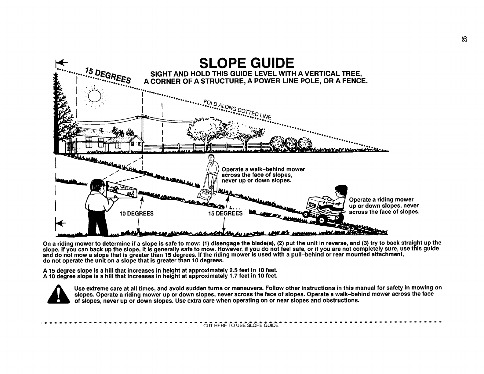
4- SLOPE GUIDE
........ :..../.b" DE_D_... SIGHT AND HOLD THIS GUIDE LEVEL WITH A VERTICAL TREE,
I ".... -'..'.._S A CORNER OF A STRUCTURE, A POWER LINE POLE, OR A FENCE.
j ........................
...... .....................
!
I
I
Operate a walk-behind mower
across the face of slopes,
never up or down slopes.
10 DEGREES 15 DEGREES
Operate a riding mower
up or down slopes, never
across the face of slopes.
On a riding mower to determine if a slope is safe to mow: (1) disengage the blade(s), (2) put the unit in reverse, and (3) try to back straight up the
slope. If you can back up the slope, it is generally safe to mow. However, if you do not feel safe, or if you are not completely sure, use this guide
anddo not mow a slope that is greater than 15 degrees. If the riding mower is used with a pull-behind or rear mounted attachment,
do not operate the und on a slope that is greater than 10 degrees.
A 15 degree slope is a hill that increases in height at approximately 2.5 feet in 10 feet.
A 10 degree slope is a hill that increases in height at approximately 1.7 feet in 10 feet.
Use extreme care at all times, and avoid sudden turns or maneuvers. Follow other instructions in this manual for safety in mowing on
slopes. Operate a riding mower up or down slopes, never across the face of slopes. Operate a walk-behind mower across the face
of slopes, never up or down slopes. Use extra care when operating on or near slopes and obstructions.
................................. _U'T_E'R_fO'U§E'_GP__&_D'E.................................

21" STEELDECK
WALKMOWERS
SERIES19
Product Specifications
Deck Size
Height of Cut
TransmissionType
Ground Speed
Engine Power- Briggs (Quantum)
Engine Power- Briggs (Intek)
Engine Power- Kawasaki
EngineDisplacement-Briggs(all)
EngineDisplacement-Kawasaki
FuelTankCapacity- Briggs(all)
FuelTankCapacity- Kawasaki
21 in
1.25 - 4 in
Gear
1 - 4 mph
6.50 ft-lbs (gross torque)
8.75 ft-lbs (gross torque)
6.0 hp (gross)
190 cc
180 cc
1.6 qt
2.1 qt
CommonServiceParts
Cutter Blade(Air-Lift Compatible)
Drive Belt(Engine)
Drive Belt(Transmission)
Parts Manual
Part Number
7019795
7046784
7012354
7006150
EnginePower RatingInformation:The gross power rating for individual gasengine models is labeled in accordancewith
SAE(Societyof Automotive Engineers)codeJ1940 (Small Engine Power& Torque Rating Procedure),and rating perform-
ancehasbeen obtainedand corrected in accordancewith SAEJ1995 (Revision 2002-05). Torquevalues are derived at 3060
RPM;horsepower values are derived at 3600 RPM.Actual gross engine power will belower and is affectedby, among other
things, ambient operatingconditions and engine-to-engine variability. Givenboth the wide array of products on which engines
are placedand the variety of environmental issues applicableto operating the equipment, the gas enginewill not developthe
ratedgross power when used in a given pieceof power equipment (actual "on-site"or net power). This difference is due to a
variety of factors including, but not limited to, accessories(air cleaner,exhaust, charging, cooling, carburetor,fuel pump,
etc.), application limitations, ambient operating conditions (temperature, humidity, altitude), and engine-to-enginevariability.
Dueto manufacturing and capacity limitations, Briggs & Stratton may substitute an engine of higher ratedpower for this
Seriesengine.
SnapperProducts
535 Macon Street
McDonough, GA30253
26
1-000-935-2967
www.snapper.com