Loading ...
Loading ...
Loading ...
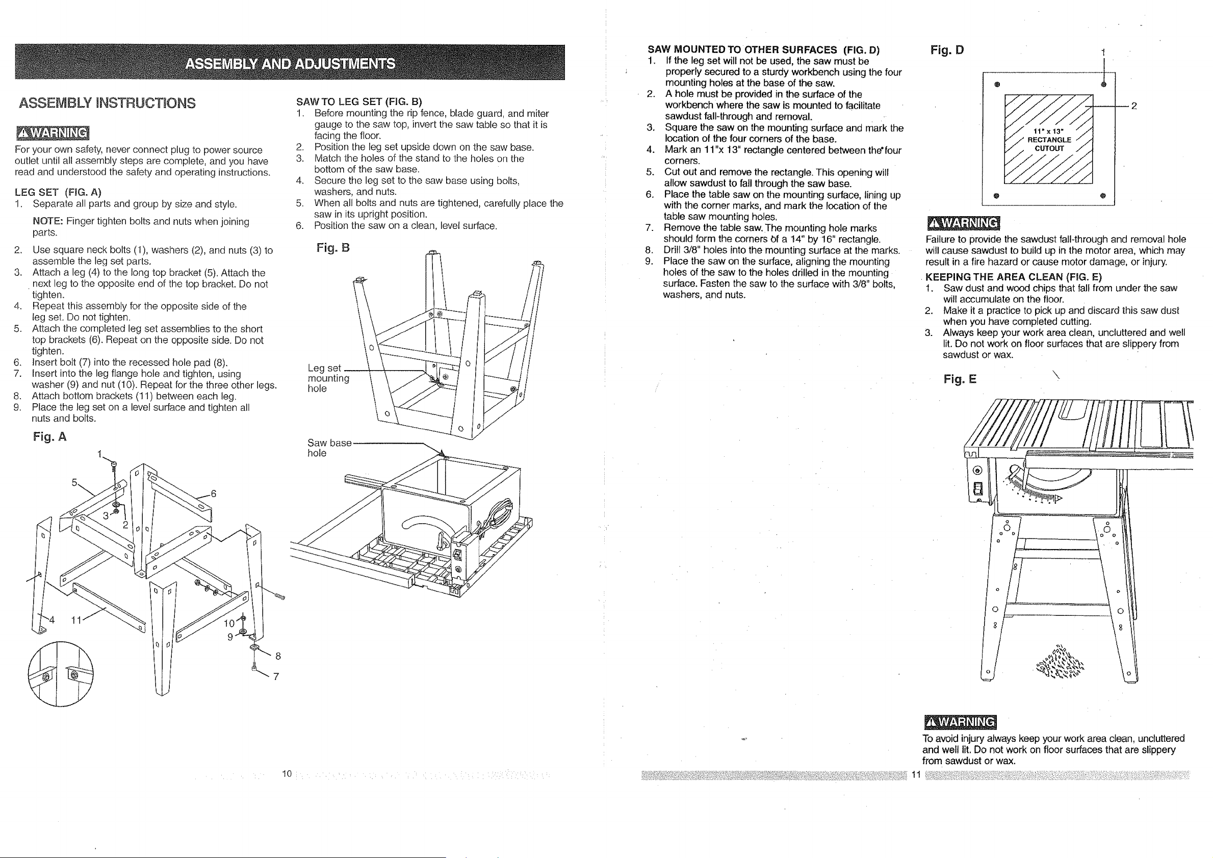
ASSEMBLY nNSTRUCTtONS
For your own safety, never connect plug to power source
ou[let until all assembly steps are complete, and you have
read and understood the safety and operating instructions.
LEG SET (FIG.A)
1. Separate all parts and group by size and style.
NOTE: Finger tighten bolts and nuts when joining
parts.
2. Use square neck bolts (1), washers (2), and nuts (3) to
assemble the leg set parts.
3. Attach a leg (4) to the long top bracket (5). Attach the
next leg to the opposite end of the top bracket. Do not
tighten.
4. Repeat this assembly for the opposite side of the
leg set. Do not tighten.
5. Attach the completed leg set assemblies to the short
top brackets (6). Repeat on the opposite side. Do not
tighten.
6. Insert bolt (7) into the recessed hole pad (8).
7. Insert into the leg flange hole and tighten, using
washer (9) and nut (10). Repeat for the three other legs.
8. Attach bottom brackets (11) between each leg.
9. Place the leg set on a level surface and tighten all
nuts and bolts.
Fig.A
11
SAW TO LEG SET (FIG. B)
1. Before mounting the rip fence, blade guard, and miter
gauge to the saw top, invert the saw table so that it is
facing the floor.
2. Position the leg set upside down on the saw base.
3. Match the holes of the stand to the holes on the
bottom of the saw base.
4. Secure the leg set to the saw base using bolts,
washers, and nuts.
5. When all bolts and nuts are tightened, carefully place the
saw in its upright position.
6. Position the saw on a clean, level surface.
Fig. B
Leg
mounting
hole
Saw base
hole
10: • ' .... : , _: ..... : : :: :i::: i: :':i¸¸ :'
SAW MOUNTED TO OTHER SURFACES (FIG. D)
1. if the leg set will not be used, the saw must be
properly secured to a sturdy workbench using the four
mounting holes at the base of the saw.
2. A hole must be provided in the surface of the
workbench where the saw is mounted to facilitate
sawdust fall-through and removal.
3. Square the saw on the mounting surface and mark the
location of the four corners of the base.
4. Mark an 11"x t3" rectangle centered between the'four
corners.
5. Cut out and remove the rectangle. This opening will
allow sawdust to fail through the saw base.
6. Place the table saw on the mounting surface, lining up
with the corner marks, and mark the location of the
table saw mounting holes.
7. Remove the table saw.The mounting hole marks
should form the corners bf a 14" by 16" rectangle.
8. Drill 3/8" holes into the mounting surface at the marks.
9. Place the saw on the surface, aligning the mounting
holes of the sawto the holes drilled in the mounting
surface. Fasten the saw to the surface with 3/8" bolts,
washers, and nuts.
Fig, D
o
1
2
Failure to provide the sawdust fatl4hrough and removal hole
will cause sawdust to build up in the motor area, which may
result in a fire hazard or cause motor damage, or injury.
KEEPING THE AREA CLEAN (FIG. E)
1. Saw dust and wood chips that fall from under the saw
will accumulate on the floor.
2. Make it a practice to pick up and discard this saw dust
when you have completed cutting.
3. Always keep your work area clean, uncluttered and well
lit. Do not work on floor surfaces that are slippery from
sawdust or wax.
Fig. E
\
To avoid injury always keep your work area clean, uncluttered
and well lit. Do not work on floor surfaces that are slippery
from sawdust or wax.
Loading ...
Loading ...
Loading ...