Loading ...
2
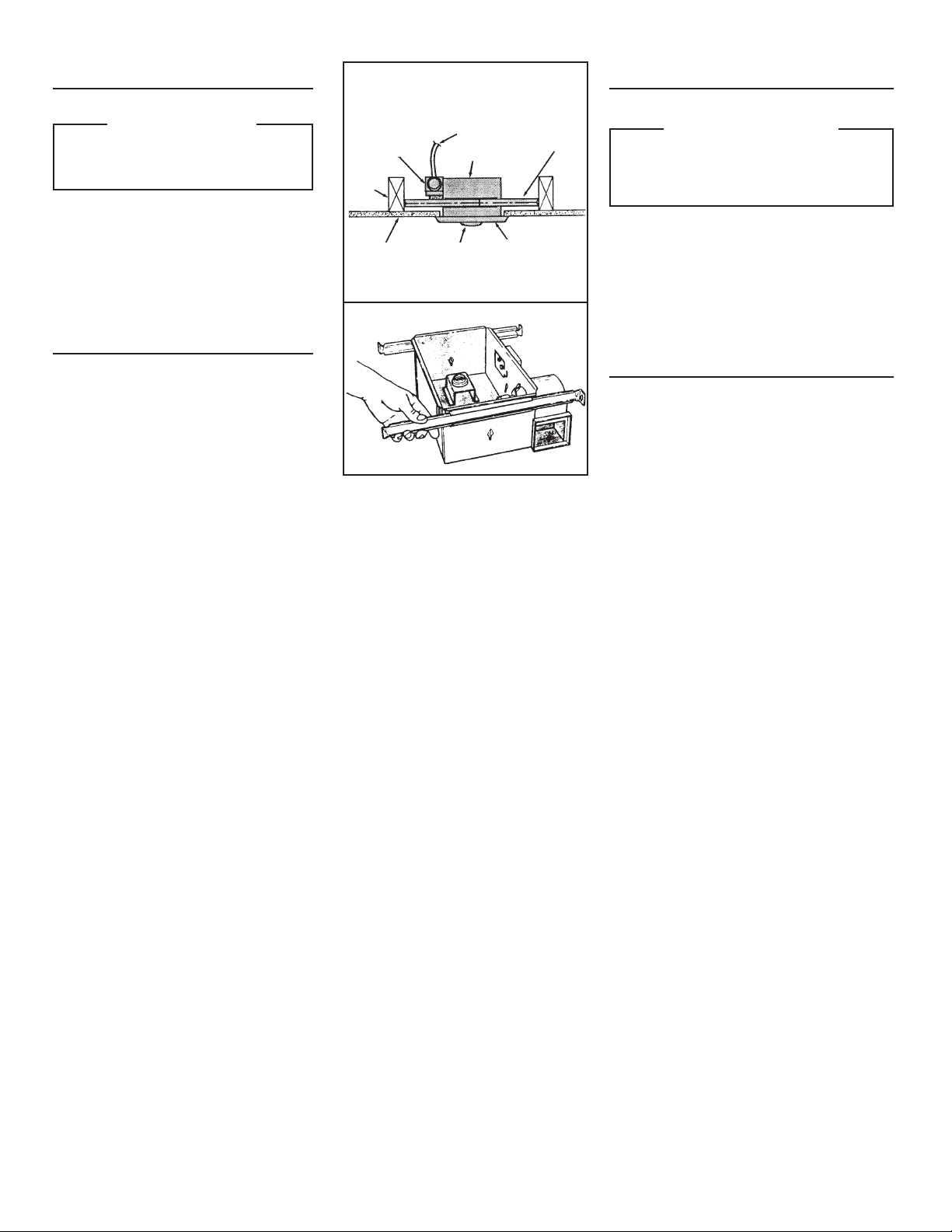
FIG. 1
CEILING MATE-
RIAL
MATERIAL DEL
CIELO RASO
GRILLE
REJILLA
DAMPER/DUCT CON-
NECTOR (162 & 164
ONLY)
AMORTIGUADOR/
ACOPLE DE CON-
DUCTO (162 Y 164
SOLAMENTE)
POWER
CABLE
CABLE DE
POTENCIA
HOUSING
CAJA
MOUNTING
BRACKET
SOPORTE DE
MONTAJE
CEILING
JOIST
VIGA DEL
CIELO
RASO
BULB(S)
BOMBILLA
FIG. 2
PLANNING
Choose the location for your heater. Refer to "IMPORTANT
INSTRUCTIONS" above.
MODELS 162 & 164 ONLY:
THE UNIT WILL OPERATE MOST EFFICIENTLY WHEN LO-
CATED WHERE THE SHORTEST POSSIBLE DUCT RUN AND
MINIMUM NUMBER OF ELBOWS WILL BE NEEDED. UNITS
ARE DESIGNED FOR USE WITH STANDARD 4" ROUND DUCT.
Note that two-bulb units (163 & 164) can be fitted with one
infrared bulb (for heat) and one reflector bulb (for light). Dual
or multi-controls can be used for separate control of bulbs
and/or exhaust fan. Purchase controls separately.
Follow these basic steps when installing this unit: (Fig. 1)
• Nailunittojoists.
• Attachductwork(Models162or164only).
• Connectpowercable.
• Fastengrilletohousing.
PREPARATION
1. Remove the unit from carton. Save carton for use
as plaster shield in rough-in installations.
2. Slide adjustable mounting brackets into bracket
channels on housing. (Fig. 2)
PLANIFICACION
Escoja un lugar para su calentador. Lea las instrucciones de “INS-
TRUCCIONES IMPORTANTES” que aparecen arriba.
MODELOS 162 & 164 SOLAMENTE:
LA UNIDAD FUNCIONARÁ EN FORMA MÁS EFICIENTE SI SE
UBICA EN UN LUGAR DONDE SE MINIMICE EL TENDIDO DE
CONDUCTOS Y EL NÚMERO DE CODOS. LAS UNIDADES HAN
SIDO DISEÑADAS PARA USO CON CONDUCTO REDONDO
ESTÁNDAR DE 10 cm.
Note que las unidades de dos bombillas (163 & 164) pueden mon-
tarse con una bombilla infrarroja (para la calefacción) y una bombilla
reflectora (para la luz). Se pueden usar controles dobles o múltiples
para un control separado de las bombillas y/o ventilador extractor
de aire. Los controles se compran por separado.
Al instalar esta unidad, siga los siguientes pasos básicos: (Fig. 1)
• Clavelaunidadalasvigas.
• Fijelosconductos(modelos162o164solamente).
• Conecteelcabledepotencia.
• Fijelarejillaalacaja.
PREPARACION
1. Saque la unidad de la caja de cartón. Guarde la caja de
cartón para su uso como escudo de yeso al principio de una
instalación.
2. Meta los soportes de montaje ajustables en los canales de
soporte en la caja. (Fig. 2)
Loading ...
Loading ...
Loading ...