EnglishFrançaisEspañol
MODELS
2MXS18NMVJU
3MXS24NMVJU
4MXS36NMVJU
2MXL18QMVJU
3MXL24QMVJU
DAIKIN ROOM AIR CONDITIONER
INSTALLATION MANUAL
R410A Split Series
Installation manual
Manuel dinstallation
Manual de instalación
Manuel dinstallation
00_CV_3P379970-8B.indd 1 11/4/2015 15:32:58
1 ■English
Contents
Safety Considerations .................................... 1
Accessories ..................................................... 3
Precautions for Selecting a Location ........... 3
Precautions on Installation ............................ 4
Outdoor Unit Installation Diagram ................ 4
Connections (connection port) ..................... 5
How to Use Reducers ..................................... 6
Installation Space Requirements .................. 7
Selecting a Location for Installation of the
Indoor Units ..................................................... 7
Outdoor Unit Installation ................................ 8
1. Installing the outdoor unit ............................................ 8
2. Drain work ................................................................... 8
3. Refrigerant piping ........................................................ 8
4. Pressure test and evacuating system .......................... 9
5. Rellingrefrigerant ...................................................... 10
6. Charging with refrigerant ............................................. 10
7. Refrigerant piping work .............................................. 11
8. Flaring the pipe end ..................................................... 11
Wiring ............................................................... 12
Priority Room Setting ..................................... 14
Night Quiet Mode setting ............................... 15
COOL/ HEAT mode lock [S15] ....................... 15
Pump Down Operation ................................... 16
Trial Operation and Testing ............................ 17
1. Wiring error check ....................................................... 17
2. Tr ial operation and testing ........................................... 18
3. Test items .................................................................... 18
Safety Considerations
Read these Safety Considerations for Installation carefully
before installing an air conditioner or heat pump. After completing
the installation, make sure that the unit operates properly during
the startup operation.
Instruct the user on how to operate and maintain the unit.
Inform users that they should store this installation manual with
the operation manual for future reference.
Always use a licensed installer or contractor to install this product.
Improper installation can result in water or refrigerant leakage,
electricshock,re,orexplosion.
Meanings of DANGER, WARNING, CAUTION, and NOTE
Symbols:
DANGER
...........
Indicates an imminently hazardous
situation which, if not avoided, will
result in death or serious injury.
WARNING
.........
Indicates a potentially hazardous
situation which, if not avoided, could
result in death or serious injury.
CAUTION
..........
Indicates a potentially hazardous
situation which, if not avoided, may
result in minor or moderate injury.
It may also be used to alert against
unsafe practices.
NOTE
................
Indicates situations that may result
in equipment or property-damage
accidents only.
DANGER
• Refrigerantgasisheavierthanairandreplacesoxygen.
Amassiveleakcanleadtooxygendepletion,especially
inbasements,andanasphyxiationhazardcouldoccur
leading to serious injury or death.
•
Do not ground units to water pipes, gas pipes, telephone
wires, or lightning rods as incomplete grounding can cause
a severe shock hazard resulting in severe injury or death.
Additionally, grounding to gas pipes could cause a gas leak
andpotentialexplosioncausingsevereinjuryordeath.
• If refrigerant gas leaks during installation, ventilate the
areaimmediately.Refrigerantgasmayproducetoxicgas
ifitcomesintocontactwithre.Exposuretothisgascould
cause severe injury or death.
• After completing the installation work, check that the
refrigerant gas does not leak throughout the system.
• Donotinstallunitinanareawhereammablematerials
arepresentduetoriskofexplosionsthatcancause
serious injury or death.
• Safely dispose all packing and transportation materials
in accordance with federal/state/local laws or ordinances.
Packing materials such as nails and other metal or
wood parts, including plastic packing materials used for
transportation may cause injuries or death by suffocation.
WARNING
• Onlyqualiedpersonnelmustcarryouttheinstallation
work. Installation must be done in accordance with this
installation manual. Improper installation may result in
waterleakage,electricshock,orre.
• When installing the unit in a small room, take measures
tokeeptherefrigerantconcentrationfromexceeding
allowablesafetylimits.Excessiverefrigerantleaks,inthe
event of an accident in a closed ambient space, can lead
tooxygendeciency.
• Useonlyspeciedaccessoriesandpartsforinstallation
work.Failuretousespeciedpartsmayresultinwater
leakage,electricshock,re,ortheunitfalling.
• Install the air conditioner or heat pump on a foundation
strong enough that it can withstand the weight of the unit.
Afoundationofinsufcientstrengthmayresultintheunit
falling and causing injuries.
01_EN_3P379970-8B.indd 1 11/17/2015 9:11:12
2■English
• Take into account strong winds, typhoons, or earthquakes
when installing. Improper installation may result in the unit
falling and causing accidents.
• Make sure that a separate power supply circuit is provided
for this unit and that all electrical work is carried out by
qualiedpersonnelaccordingtolocal,state,andnational
regulations.Aninsufcientpowersupplycapacityor
improper electrical construction may lead to electric shock
orre.
• Makesurethatallwiringissecured,thatspeciedwires
areused,andthatnoexternalforcesactontheterminal
connections or wires. Improper connections or installation
mayresultinre.
• When wiring, position the wires so that the electrical
wiringboxcovercanbesecurelyfastened.Improper
positioningoftheelectricalwiringboxcovermayresultin
electricshock,re,ortheterminalsoverheating.
• Before touching electrical parts, turn off the unit.
• It is recommended to install a ground fault circuit
interrupter if one is not already available. This helps
preventelectricshockorre.
•
Securely fasten the outdoor unit terminal cover (panel). If the
terminal cover/panel is not installed properly, dust or water
mayentertheoutdoorunitcausingreorelectricshock.
•
When installing or relocating the system, keep the refrigerant
circuitfreefromsubstancesotherthanthespecied
refrigerant (R410A) such as air. Any presence of air or other
foreign substance in the refrigerant circuit can cause an
abnormal pressure rise or rupture, resulting in injury.
• Do not change the setting of the protection devices. If the
pressure switch, thermal switch, or other protection device
is shorted and operated forcibly, or parts other than those
speciedbyDaikinareused,reorexplosionmayoccur.
CAUTION
• Donottouchtheswitchwithwetngers.Touchingaswitch
withwetngerscancauseelectricshock.
• Do not allow children to play on or around the unit to
prevent injury.
• Theheatexchangernsaresharpenoughtocut.To avoid
injurywearglovesorcoverthenswhileworkingaround
them.
• Do not touch the refrigerant pipes during and immediately
after operation as the refrigerant pipes may be hot or
cold,dependingontheconditionoftherefrigerantowing
through the refrigerant piping, compressor, and other
refrigerant cycle parts. Your hands may suffer burns or
frostbite if you touch the refrigerant pipes. To avoid injury,
give the pipes time to return to normal temperature or, if
you must touch them, be sure to wear proper gloves.
• Install drain piping to proper drainage. Improper drain
piping may result in water leakage and property damage.
• Insulate piping to prevent condensation.
• Be careful when transporting the product.
• Do not turn off the power immediately after stopping
operation. Always wait for at least 5 minutes before turning
off the power. Otherwise, water leakage may occur.
• Do not use a charging cylinder. Using a charging cylinder
may cause the refrigerant to deteriorate.
• Refrigerant R410A in the system must be kept clean, dry,
and tight.
(a) Clean and Dry -- Foreign materials (including mineral
oils such as SUNISO oil or moisture) should be
prevented from getting into the system.
(b)
Tight -- R410A does not contain any chlorine, does not
destroy the ozone layer, and does not reduce the earth’s
protection again harmful ultraviolet radiation. R410A
can contribute to the greenhouse effect if it is released.
Therefore take proper measures to check for the tightness
of the refrigerant piping installation. Read the chapter
Refrigerant Piping Work and follow the procedures.
• Since R410A is a blend, the required additional refrigerant
must be charged in its liquid state. If the refrigerant is
charged in a state of gas, its composition can change and
the system will not work properly.
• The indoor unit is for R410A. See the catalog for indoor
models that can be connected. Normal operation is not
possible when connected to other units.
•
Remote controller (wireless kit) transmitting distance can be
shorterthanexpectedinroomswithelectronicuorescent
lamps (inverter or rapid start types). Install the indoor unit
farawayfromuorescentlampsasmuchaspossible.
•
Indoor units are for indoor installation only. Outdoor units can be
installed either outdoors or indoors. This unit is for indoor use.
• Do not install the air conditioner or heat pump in the
following locations:
(a) Where a mineral oil mist or oil spray or vapor is
produced,forexample,inakitchen.
Plastic parts may deteriorate and fall off or result in
water leakage.
(b) Where corrosive gas, such as sulfurous acid gas, is
produced.
Corroding copper pipes or soldered parts may result in
refrigerant leakage.
(c) Near machinery emitting electromagnetic waves.
Electromagneticwavesmaydisturbtheoperationof
the control system and cause the unit to malfunction.
(d)Whereammablegasmayleak,wherethereiscarbon
ber,orignitabledustsuspensionintheair,orwhere
volatileammablessuchasthinnerorgasolineare
handled. Operating the unit in such conditions can
causeare.
• Take adequate measures to prevent the outdoor unit
from being used as a shelter by small animals. Small
animals making contact with electrical parts can cause
malfunctions,smoke,orre.Instructtheusertokeepthe
area around the unit clean.
NOTE
• Install the power supply and inter-unit wires for the indoor
and outdoor units at least 3.5ft away from televisions or
radios to prevent image interference or noise. Depending
on the radio waves, a distance of 3.5ft may not be
sufcienttoeliminatethenoise.
• Dismantling the unit, treatment of the refrigerant, oil and
additional parts must be done in accordance with the
relevant local, state, and national regulations.
•
Do not use the following tools that are used with
conventional refrigerants: gauge manifold, charge hose, gas
leakdetector,reverseowcheckvalve,refrigerantcharge
base, vacuum gauge, or refrigerant recovery equipment.
• If the conventional refrigerant and refrigerator oil are
mixedinR410A,therefrigerantmaydeteriorate.
• This air conditioner or heat pump is an appliance that
should not be accessible to the general public.
• Asdesignpressureis478psi,thewallthicknessofeld-
installed pipes should be selected in accordance with the
relevant local, state, and national regulations.
English
01_EN_3P379970-8B.indd 2 11/17/2015 9:11:12
3 ■English
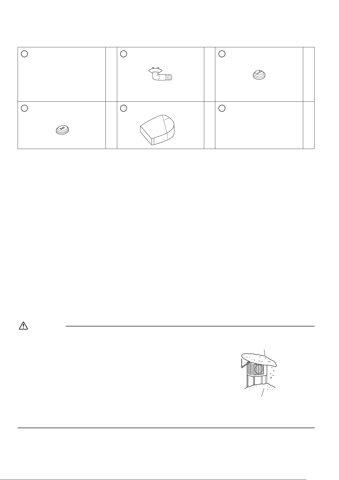
Accessories
A
Installation manual
1
B
Drain socket
This is at the bottom of the
packaging.
1
C
Drain cap (1)
6
D
Drain cap (2)
3
E
Reducer assy
1
F
Warranty
1
Precautions for Selecting a Location
1) Chooseaplacesolidenoughtobeartheweightandvibrationoftheunit,wheretheoperatingsoundwillnotbeamplied.
2) Choose a location where the hot air discharged from the unit or the operating sound will not cause a nuisance to the
neighbors of the user.
3) Avoid locations, such as near bedrooms, where the operating sound may cause disturbance.
4) Theremustbesufcientspacetocarrytheunitintoandoutofthesite.
5) Theremustbesufcientspaceforairpassageandnoobstructionsaroundtheairinletandtheairoutlet.
6) Thesitemustnotbepronetoammablegasleaksinthesurroundingarea.
7) Install units, power cords, and inter-unit wires at least 10ft (3m) from television and radio sets. (This is to prevent interference
to images and sounds. Noise may be produced even if they are more than 10ft (3m) away depending on radio wave
conditions.)
8) In coastal areas or other places with salty atmosphere or one containing sulphate gas, corrosion may shorten the life of the
air conditioner.
9) Sincewaterwillowfromthedrainoftheoutdoorunit,donotplaceundertheunitanythingwhichmustbekeptawayfrom
moisture.
NOTE
Cannot be installed suspended from a ceiling or stacked.
CAUTION
When operating the air conditioner in a low outdoor ambient temperature, be sure to
follow the instructions described below.
• Topreventexposuretowind,installtheoutdoorunitwithitssuctionsidefacingthe
wall.
• Neverinstalltheoutdoorunitatasitewherethesuctionsidemaybeexposed
directly to wind.
• Topreventexposuretowind,itisrecommendedtoinstallabafeplateontheair
discharge side of the outdoor unit.
• In heavy snowfall areas, select an installation site where the snow will not affect the
unit.
• If there is a likelihood of snow accumulating on the outdoor unit, attach a snow
protection hood.
• In high humidity areas or heavy snow areas, it is recommended to attach a drain
pan heater to prevent ice build-up from the bottom frame.
•Construct a large canopy.
•Construct a pedestal.
Install the unit high enough off
the ground to prevent burying
in snow.
01_EN_3P379970-8B.indd 3 11/17/2015 9:11:13
4■English
Precautions on Installation
• Check the strength and level of the installation surface so that the unit does not cause
any operating vibrations or noise after installation.
• Fixtheunitinplacesecurelyusingfoundationbolts,asinthegure.(Prepare4sets
of 5/16 inch (M8) or 3/8 inch (M10) foundation bolts, nuts and washers; all separately
available.)
• It is best to screw in the foundation bolts until their ends are 3/4 inch (20mm) from the
foundation surface.
3/4”
(20mm)
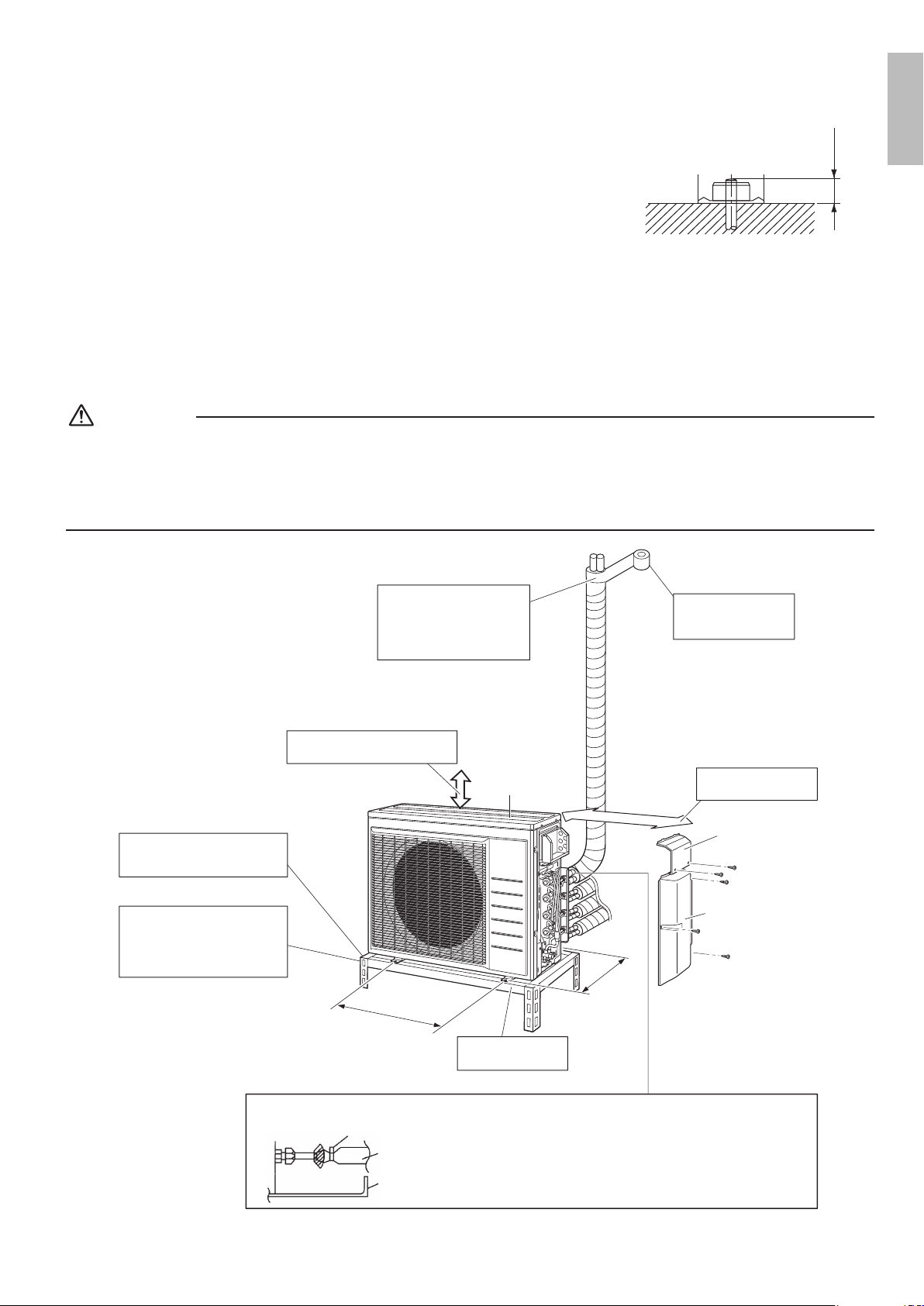
Outdoor Unit Installation Diagram
CAUTION
• Do not connect the embedded branch piping and the outdoor unit when only carrying out piping work without connecting the
indoor unit in order to add another indoor unit later.
Make sure no dirt or moisture gets into either side of the embedded branch piping.
Refer to “7. Refrigerant piping work” on page 11 for details.
• It is not possible to have only 1 indoor unit connected. Be sure to connect at least 2 indoor units.
Cut thermal insulation pipe to
an appropriate length and
wrap it with tape, making sure
that no gap is left in the
insulation pipe’s cut line.
Wrap the insulation pipe
with finishing tape from
bottom to top.
9-13/16 (250) from wall
Allow space for piping
and electrical servicing.
Level mounting base
(available separately)
Where there is a danger of the
unit falling, use foot bolts, or
wires.
In sites with poor drainage, use
block bases for the outdoor unit.
Adjust foot height until the unit is
level. Otherwise, water leakage
or pooling of water may occur.
Also insulate the connection on the outdoor unit.
Use tape or insulating material on all connections to prevent air
from getting in between the copper piping and the insulation
tube.
Be sure to do this if the outdoor unit is installed at a higher
elevation than are any of the indoor units connected to it.
Stop valve cover
Service lid
13-5/8 (346)
(Foot bolt-hole
centers)
(Foot bolt-hole centers)
23-5/8 (600)
Allow 11-13/16” (300mm) of work
space below the ceiling surface.
Clamping material
Insulation tube
Stop valve cover
Tape
unit : inch (mm)
Top plate
English
01_EN_3P379970-8B.indd 4 11/17/2015 9:11:13
5 ■English
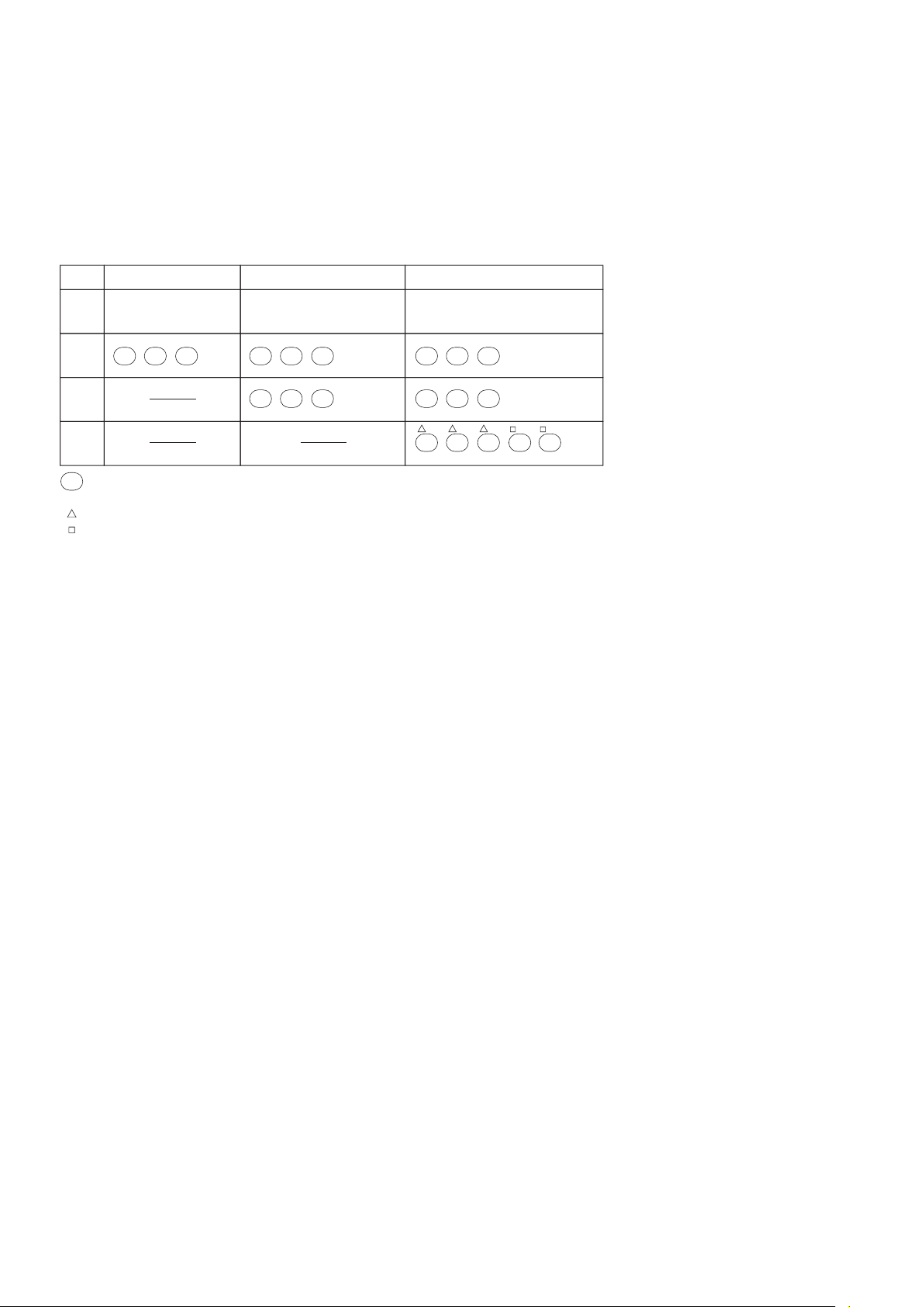
Connections (connection port)
Install the indoor unit according to the table below, which shows the relationship between the class of indoor unit and the
corresponding port.
The total indoor unit class that can be connected to this unit:
2MXS18*, 2MXL18* – Up to 24000 Btu
3MXS24*, 3MXL24* – Up to 39000 Btu
4MXS36* – Up to 48000 Btu
Thelinesetpipingsizeisdeterminedbythesizeoftheindoorunitttings.
Reducers are used at the outdoor unit to accommodate the correct gas line pipe size.
3MXS24∗, 3MXL24∗ 4MXS36∗
Port
2MXS18∗, 2MXL18∗
B
07 , 09 , 12 , ,15 1807 , 09 , 12 , 15 07 , 09 , 12 , ,15 18
D
07 , 09 , 12 , ,15 18 , 24
A
07 , 09
,
12
07 , 09
,
12
07 , 09
,
12
C
07 , 09 , 12 , ,15 18 07 , 09 , 12 , ,15 18
: Use a reducer to connect pipes.
: Use No. 2 and 4 reducers
: Use No. 5 and 6 reducers
: Use No. 1 and 3 reducers
#
###
######
###
###
Refer to “How to Use Reducers” on page 6 for information on reducer numbers and their shapes.
01_EN_3P379970-8B.indd 5 11/17/2015 9:11:14
6■English
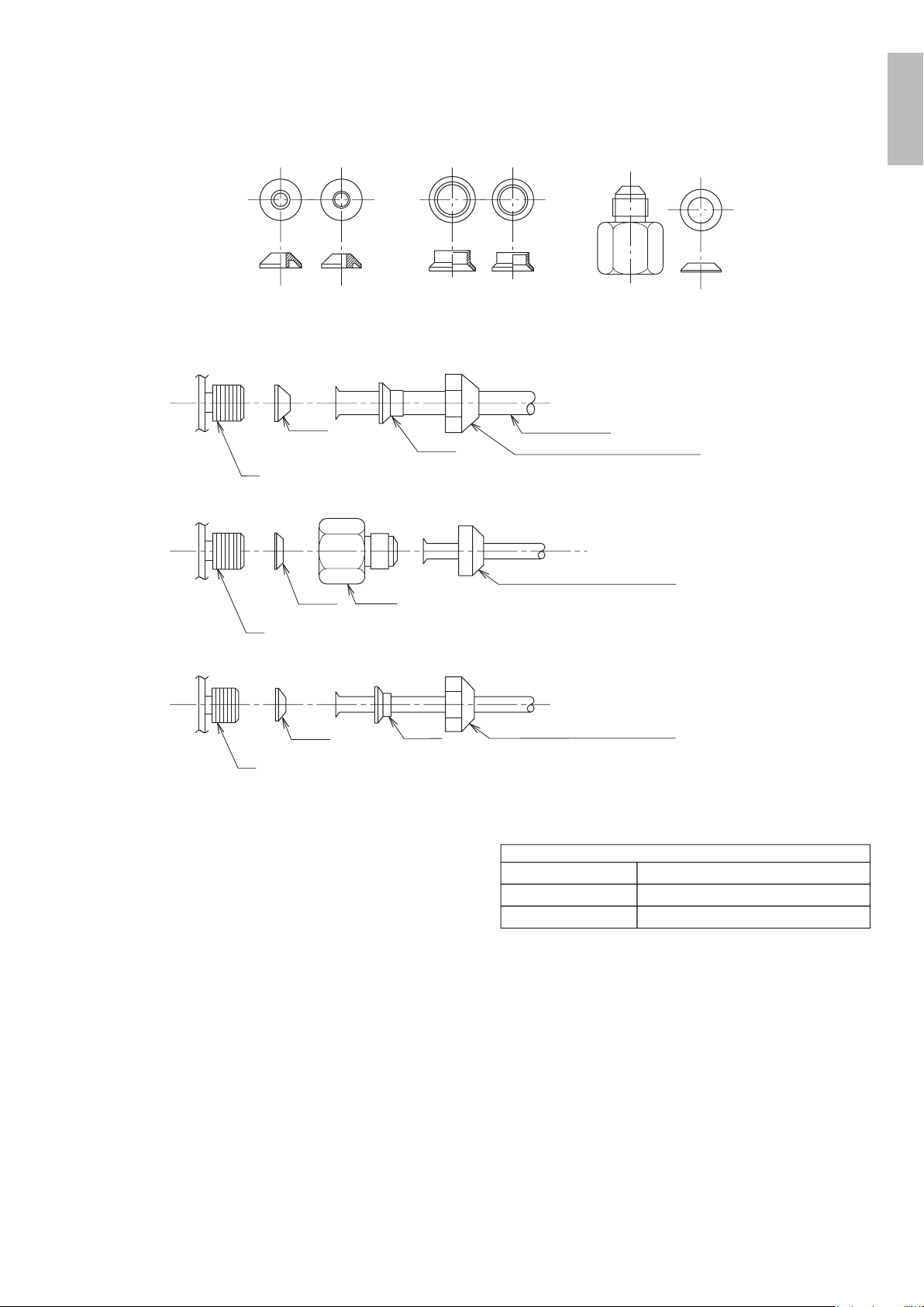
How to Use Reducers
• Use the reducers supplied with the unit as described below.
(1) Connecting a pipe of φ1/2 inch (12.7mm) to a gas pipe connection port for φ5/8 inch (15.9mm) :
(2) Connecting a pipe of φ3/8 inch (9.5mm) to a gas pipe connection port for φ5/8 inch (15.9mm) :
(3) Connecting a pipe of φ3/8 inch (9.5mm) to a gas pipe connection port for φ1/2 inch (12.7mm) :
No.1
φ5/8”
φ1/2”
No.2
φ1/2”
φ3/8”
No.3
φ5/8”
φ1/2”
No.4
φ1/2”
φ3/8”
No.5
φ5/8”
φ3/8”
No.6
φ5/8”
φ3/8”
Gasket (1) Gasket (2) Reduce and gasket
No. 1
No. 3
Flare nut (for φ5/8 inch (15.9mm))
Inter-unit piping
Connection port of outdoor unit
Connection port of outdoor unit
Connection port of outdoor unit
Be sure to attach
the gasket.
No. 5
No. 6
Flare nut (for φ3/8 inch (9.5mm))
Be sure to attach the gasket.
No. 4
No. 2
Flare nut (for φ1/2 inch (12.7mm))
Be sure to attach the gasket.
Flare nut tightening torque
φ3/8 inch (9.5mm)
φ1/2 inch (12.7mm)
φ5/8 inch (15.9mm)
24-1/8 – 29-1/2ft • Ibf (32.7-39.9N • m)
36-1/2 – 44-1/2ft • lbf (49.5-60.3N • m)
45-5/8 – 55-5/8ft • lbf (61.8-75.4N • m)
• When using the reducer packing shown above, be careful not to
overtighten the nut, or the smaller pipe may become damaged.
(Apply about 2/3 to 3/3 the normal torque.)
• Apply a coat of refrigeration oil to the threaded connection port of
theoutdoorunitwherethearenutcomesin.
• Use an appropriate wrench to avoid damaging the connection
threadbyovertighteningthearenut.
English
01_EN_3P379970-8B.indd 6 11/17/2015 9:11:14

7 ■English
Installation Space Requirements
• Whereawallorotherobstacleisinthepathofoutdoorunit’sintakeorexhaustairow,followtheinstallationspacerequirements
below.
• For any of the below installation patterns, the wall height on the outlet side should be 47-1/4 inch (1200mm) or less.
unit: inch (mm)
Top view
More than 3-15/16 (100)
More than 13-3/4 (350)
More than
1-15/16 (50)
More than
1-15/16 (50)
More than
1-15/16 (50)
Top view
More
than
3-15/16
(100)
More than
13-3/4
(350)
More than
3-15/16 (100)
More than
13-3/4 (350)
Side view
47-1/4
(1200)
or less
Wall facing one side Walls facing two sides
Walls facing three sides
More than
3-15/16 (100)
More than
13-3/4 (350)
Selecting a Location for Installation of
the Indoor Units
• Themaximumallowablelengthofrefrigerantpiping,andthemaximumallowableheightdifferencebetweentheoutdoorand
indoor units, are listed below. (The shorter the refrigerant piping, the better the performance. Connect so that the piping is as
short as possible. Shortest allowable length per room is 10ft (3m).)
If the outdoor unit is positioned higher than the indoor units. If the outdoor unit is positioned lower than
one or more indoor units.
Level
difference:
24-5/8ft (7.5m)
max.
Level
difference:
49-1/4ft (15m)
max.
Indoor unit
Outdoor unit
Level
difference:
49-1/4ft (15m)
max.
Outdoor unit
Indoor unit
Level
difference:
24-5/8ft (7.5m)
max.
Outdoor unit capacity class
Piping to each indoor unit
2MXS18∗, 2MXL18∗
82ft (25m) max.
3MXS24∗, 4MXS36∗, 3MXL24∗
Total length of piping between all units 164ft (50m) max. 230ft (70m) max.
01_EN_3P379970-8B.indd 7 11/17/2015 9:11:14

8■English
Outdoor Unit Installation
1. Installing the outdoor unit
1) When installing the outdoor unit, refer to “Precautions for Selecting a Location” on page 3 and the “Outdoor Unit
Installation Diagram” on page 4.
2) If drain work is necessary, follow the procedures below.
2. Drain work
CAUTION
In cold areas, do not use a drain socket, drain caps (1,2)
and a drain hose with the outdoor unit. (Drain water may
freeze, impairing heating performance.)
• Ifthedrainportiscoveredbyamountingbaseoroor
surface, place additional foot bases of at least 1-1/4
inch (30mm) in height under the outdoor unit’s feet.
1) Attach
C
drain cap (1) and
D
drain cap (2).
2) Attach
B
drain socket.
• When attaching
B
drain socket to the bottom
frame, make sure to connect the drain hose to the
drainsocketrst.
3. Refrigerant piping
CAUTION
• Usethearenutxedtothemainunit.(Thisistopreventthearenutfromcrackingasaresultofdeteriorationovertime.)
• Topreventgasleakage,applyrefrigerationoilonlytotheinnersurfaceoftheare.(UserefrigerationoilforR410A.)
• Useatorquewrenchwhentighteningthearenutstopreventdamagetothearenutsandgasleakage.
• Alignthecentersofbotharesandtightenthearenuts3or4turnsbyhand,thentightenthemfullywithaspanneranda
torque wrench.
Do not apply refrigeration
oil to the outer surface.
Flare nut
Apply refrigeration
oil to the inner
surface of the flare.
Do not apply refrigeration oil to
the flare nut to avoid tightening
with excessive torque.
Apply oil
Torque wrench
Piping union
Flare nut
Spanner
Tighten
Flare nut tightening torque
φ1/4 inch (6.4mm)
φ3/8 inch (9.5mm)
φ1/2 inch (12.7mm)
φ5/8 inch (15.9mm)
10-1/2 – 12-3/4ft • lbf (14.2-17.2N • m)
24-1/8 – 29-1/2ft • Ibf (32.7-39.9N • m)
36-1/2 – 44-1/2ft • lbf (49.5-60.3N • m)
45-5/8 – 55-5/8ft • lbf (61.8-75.4N • m)
Width across flats
Valve cap tightening torque
Service port cap tightening torque
8–10-7/8ft • lbf
(10.8-14.7N • m)
11/16 inch (17mm)
10-1/2 – 12-5/8ft • lbf
(14.2-17.2N • m)
3/4 inch (19mm)
12-5/8–15-3/8ft • lbf
(17.1-20.9N • m)
7/8 inch (22mm)
16–20-1/4ft • lbf
(21.6-27.4N • m)
1-1/16 inch (27mm)
35-3/8 – 44-1/8ft • lbf
(48-59.8N • m)
Bottom frame
Drain cap
Pinch the bottom
frame in.
Drain cap (1)
Drain cap (2)
D
Drain cap (2)
Air outlet side
B
Drain
socket
C
D
Bottom frame
Drain socket
Hose (available commercially,
inner dia. 5/8 ” (16mm))
B
English
01_EN_3P379970-8B.indd 8 11/17/2015 9:11:15
9 ■English
Outdoor Unit Installation
4. Pressure test and evacuating system
WARNING
• Donotmixanysubstanceotherthanthespeciedrefrigerant(R410A)intotherefrigerationcycle.
• If refrigerant gas leaks should occur, ventilate the room as soon and as much as possible.
• R410A, as well as other refrigerants, should always be recovered and never be released directly into the environment.
• UseavacuumpumpforR410Aexclusively.Usingthesamevacuumpumpfordifferentrefrigerantsmaydamagethevacuum
pump or the unit.
CAUTION
Itishighlyrecommendedthatyoudonotopen/closethestopvalveswhentheoutdoortemperatureisbelow−5°F(−21°C)as
this may result in refrigerant leakage.
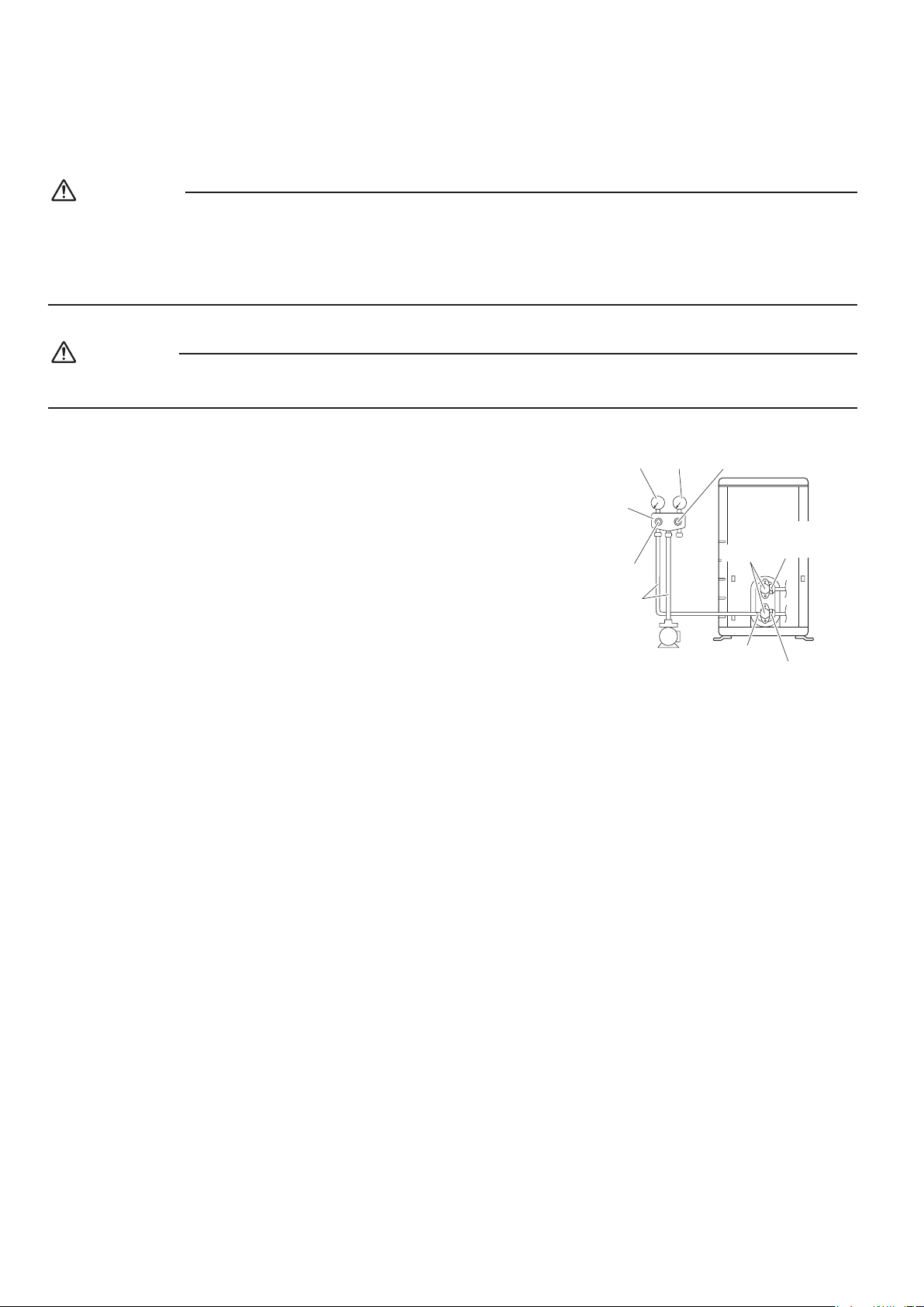
• When piping work is complete, it is necessary to perform a pressure test
and evacuate system with a vacuum pump.
• If using additional refrigerant, purge the air from the refrigerant pipes and
indoor unit using a vacuum pump, then charge additional refrigerant.
• Useahexagonalwrench(3/16inch(4mm))tooperatethestopvalverod.
• All refrigerant pipe joints should be tightened with a torque wrench to the
speciedtighteningtorque.
Compound
pressure gauge
Pressure
meter
High-pressure
valve
Low-pressure
valve
Vacuum pump
Service port
Liquid
stop
valve
Valve caps
Gas stop valve
Charging
hoses
Gauge
manifold
1) Pressurize the liquid pipe and gas pipe from the service ports of each stop valve to 550psi (3.8MPa) (do not pressurize
more than 550psi (3.8MPa)) for 1 hour minimum, 24 hours recommended. If there is a pressure drop, check for leaks,
make repairs and perform the pressure test again.
2) Connect the gauge manifold’s charging hose to the gas stop valve’s service port.
3) Fully open the gauge manifold’s low-pressure valve (Lo) and completely close its high-pressure valve (Hi).
(High-pressure valve will require no further operation.)
4) Evacuatesystemusingvacuumpumptobelow500micronsfor1hourminimum.
5) Close the gauge manifold’s low-pressure valve (Lo) and stop vacuum pump.
(Maintain this condition for 4-5 minutes to make sure that the compound pressure gauge pointer does not swing back.)*
1
6) Remove the valve caps from the liquid stop value and gas stop valve.
7) Tu r ntheliquidstopvalve’srod90°counter-clockwisewithahexagonalwrenchtoopenthevalve.
Close it after 5 seconds, and check for gas leakage.
Usingsoapywater,checkforgasleakagefromtheindoorunit’sareandoutdoorunit’sareandvalverods.
After the check is complete, wipe all soapy water off.
8) Disconnect the charging hose from the gas stop valve’s service port, then fully open liquid and gas stop valves.
(Do not attempt to turn the valve rod further than it can go.)
9) Tightenthevalvecapsandserviceportcapsfortheliquidandgasstopvalveswithatorquewrenchtothespecied
torques.
Refer to “3. Refrigerant piping” on page 8 for details.
*
1
If the compound pressure gauge pointer swings back, the refrigerant may have water content or there may be a loose
pipe joint.
Check all pipe joints and retighten nuts as needed, then repeat steps 3) through 5).
01_EN_3P379970-8B.indd 9 11/17/2015 9:11:15
10■English
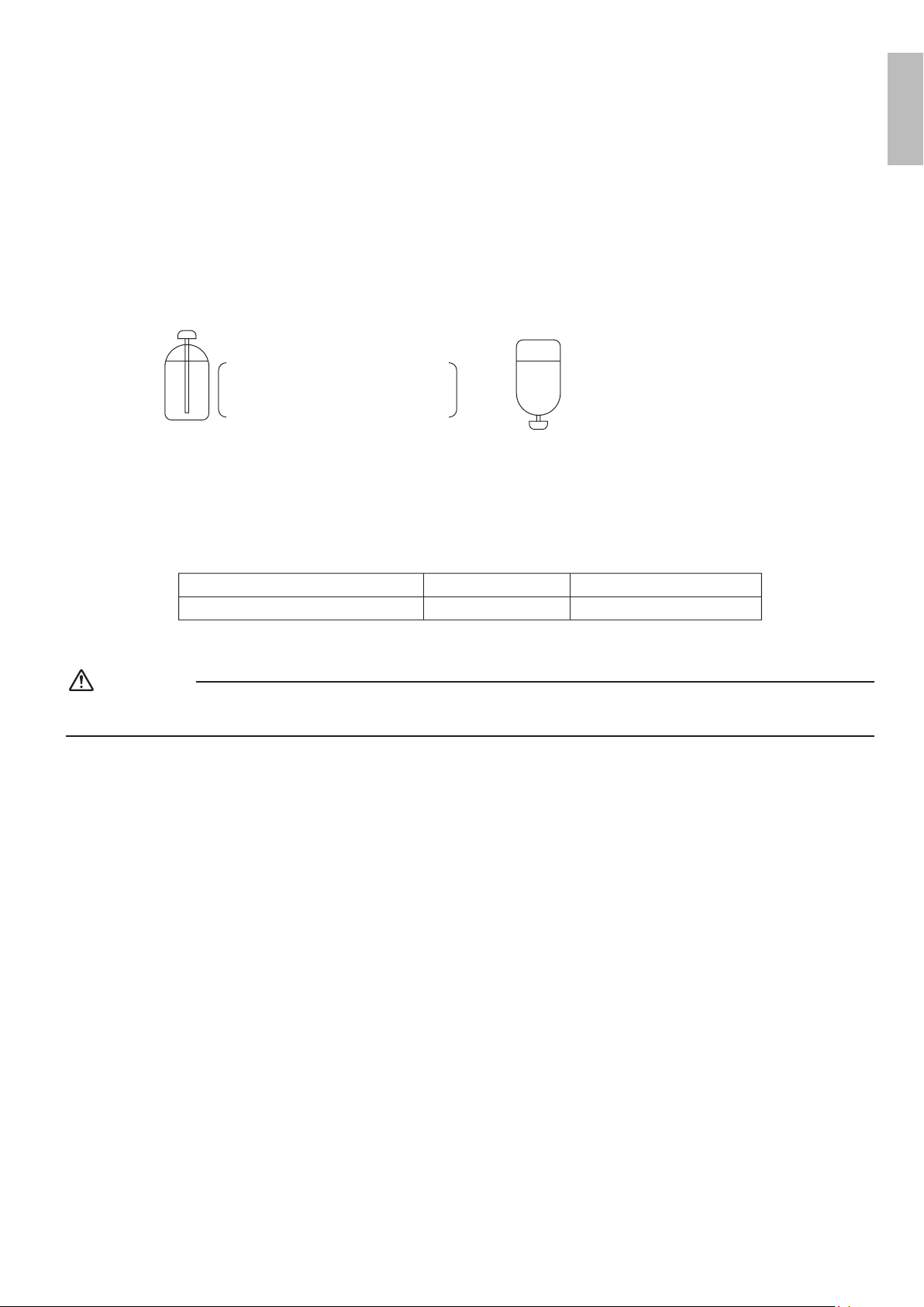
5. Relling refrigerant
Check the type of refrigerant to be used on the machine nameplate.
Precautions when adding R410A
Fill from the liquid pipe in liquid form.
R410Aisamixedrefrigerant,soaddingitingasformmaycausetherefrigerantcompositiontochange,preventingnormal
operation.
1) Beforelling,checkwhetherthecylinderhasasiphonattachedornot.(Itshouldhavesomethinglike“liquidllingsiphon
attached” displayed on it.)
Filling a cylinder with an attached siphon
Stand the cylinder upright when filling.
There is a siphon pipe inside, so the
cylinder need not be upside-down to
fill with liquid.
Filling other cylinders
Turn the cylinder upside-down
when filling.
• Be sure to use the R410A tools to ensure pressure and to prevent foreign objects entering.
6. Charging with refrigerant
• Ifthetotallengthofpipingforallroomsexceedsthegurelistedbelow,additionallychargewith0.21oz/ft(20g/m)of
refrigerant (R410A) for each additional piping length.
Outdoor unit capacity class
Total length of piping for all rooms
3MXS24∗, 4MXS36∗, 3MXL24∗
131-5/8ft (40m)
2MXS18∗, 2MXL18∗
98-3/8ft (30m)
• If additional refrigerant has been charged list the amount added on the nameplate on the reverse side of the service lid.
CAUTION
Eventhoughthestopvalveisfullyclosed,therefrigerantmayslowlyleakout;donotleavethearenutremovedforalong
period of time.
English
01_EN_3P379970-8B.indd 10 11/17/2015 9:11:15
11 ■English
Outdoor Unit Installation
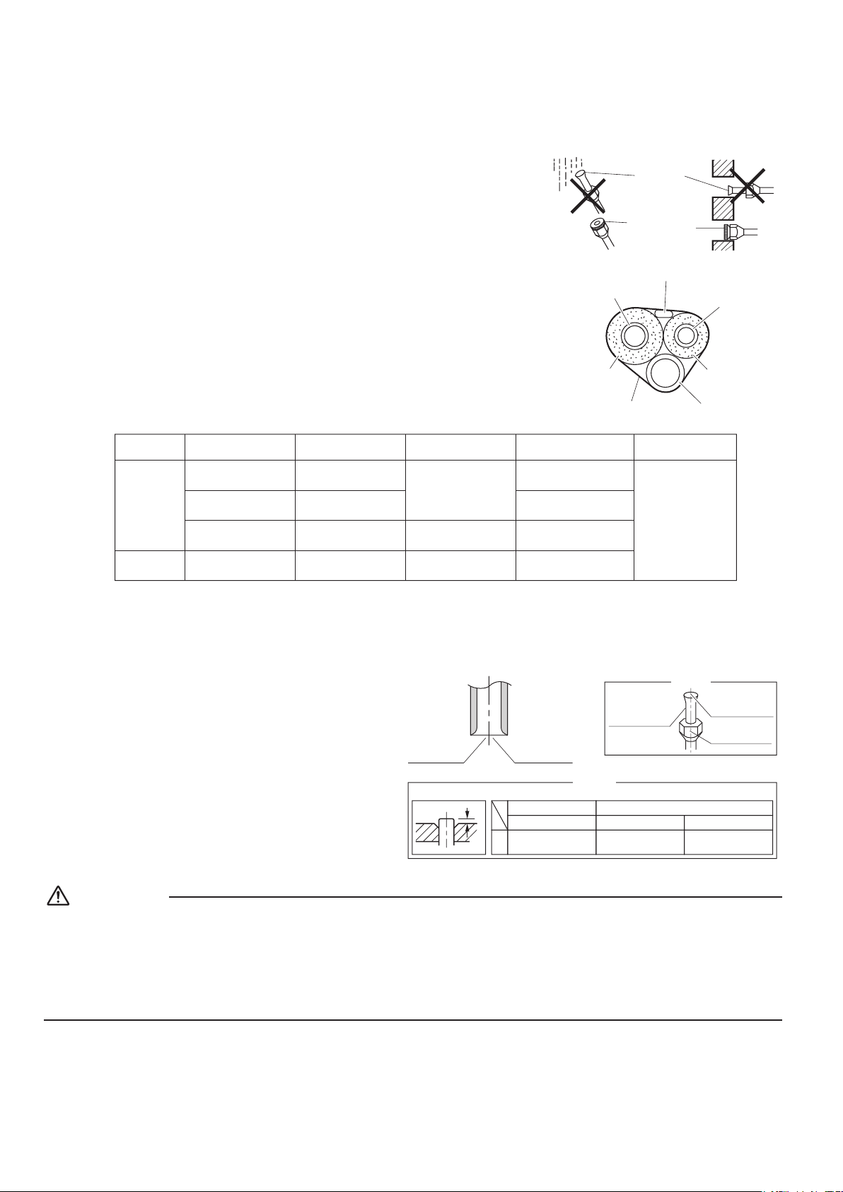
7. Refrigerant piping work
7-1. Cautions on pipe handling
• Protect the open end of the pipe from dust and moisture.
• All pipe bends should be as gentle as possible. Use a pipe bender for
bending.
7-2. Selection of copper and heat insulation materials
Whenusingcommercialcopperpipesandttings,observethefollowing:
• Insulation material: Polyethylene foam
Heattransferrate:0.041to0.052W/mK(0.024to0.030Btu/fth°F
(0.035to0.045kcal/mh°C))
Be sure to use insulation that is designed for use with HVAC Systems.
• Be sure to insulate both the gas and liquid piping and observe the
insulation dimensions as below.
Wall
If no flare cap is
available, cover
the flare mouth
with tape to keep
dirt and water out.
Be sure to
place a cap.
Rain
Gas pipe
Liquid pipe
Gas pipe
insulation
Liquid pipe
insulation
Finishing tape
Drain hose
Inter-unit wire
Gas side
Piping size
O.D. 3/8 inch
(9.5mm)
O.D. 1/2 inch
(12.7mm)
O.D. 5/8 inch
(15.9mm)
O.D. 1/4 inch
(6.4mm)
1-3/16 inch (30mm)
or more
1-9/16 inch (40mm)
or more
1-15/16 inch (50mm)
or more
1-3/16 inch (30mm)
or more
0.031 inch (0.8mm)
(C1220T-O)
0.039 inch (1.0mm)
(C1220T-O)
0.031 inch (0.8mm)
(C1220T-O)
I.D. 15/32-19/32 inch
(12-15mm)
I.D. 9/16-5/8 inch
(14-16mm)
I.D. 5/8-13/16 inch
(16-20mm)
I.D. 5/16-13/32 inch
(8-10mm)
13/32 inch
(10mm) Min.
Minimum bend radius
Piping thickness
Thermal insulation size
Thermal insulation
thickness
Liquid side
• Use separate thermal insulation pipes for gas and liquid refrigerant pipes.
8. Flaring the pipe end
1) Cut the pipe end with a pipe cutter.
2) Remove burrs with the cut surface facing downward
so that the chips do not enter the pipe.
3) Putthearenutonthepipe.
4) Flare the pipe.
5) Checkthatthearingisproperlymade.
Check
Flare’s inner
surface must
be flaw-free.
The pipe end must
be evenly flared in
a perfect circle.
Make sure that the
flare nut is fitted.
Set exactly at the position shown below.
Flaring
A
Die
A
0-0.020 inch
(0-0.5mm)
Clutch-type
Flare tool for R410A
0.039-0.059 inch
(1.0-1.5mm)
Clutch-type (Rigid-type)
0.059-0.079 inch
(1.5-2.0mm)
Wing-nut type (Imperial-type)
Conventional flare tool
Cut exactly at
right angles.
Remove burrs.
WARNING
• Donotusemineraloilonaredpart.
• Prevent mineral oil from getting into the system as this would reduce the service life of the units.
• Never use piping which has been used for previous installations. Only use parts which are delivered with the unit.
• Never install a dryer to this R410A unit in order to guarantee its service life.
• The drying material may dissolve and damage the system.
• Incompletearingmaycauserefrigerantgasleakage.
01_EN_3P379970-8B.indd 11 11/17/2015 9:11:16
12■English
Wiring
WARNING
• Donotusetappedwires,extensioncords,orstarburstconnections,astheymaycauseoverheating,electricshock,orre.
• Do not use locally purchased electrical parts inside the product. (Do not branch the power for the drain pump, etc., from the
terminalblock.)Doingsomaycauseelectricshockorre.
• Be sure to install a ground fault circuit interrupter. (One that can handle higher harmonics.)
(This unit uses an inverter. Therefore, a ground fault circuit interrupter capable of handling higher harmonics must be used in
order to prevent the ground fault circuit interrupter malfunctioning.)
• Use an all-pole disconnection type circuit breaker with at least 1/8 inch (3mm) between the contact point gaps.
• When carrying out wiring, take care not to pull at the conduit.
• Donotconnectthepowerwiretotheindoorunit.Doingsomaycauseelectricshockorre.
• Do not turn on the circuit breaker until all work is completed.
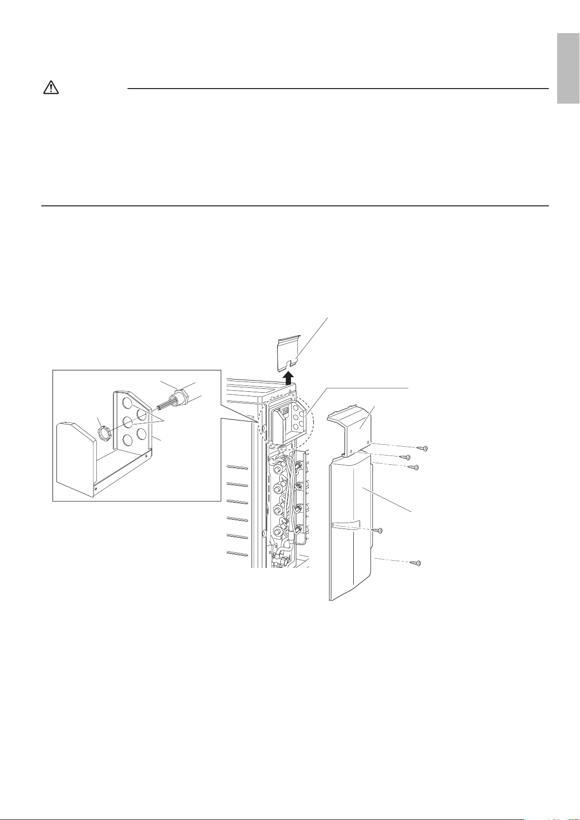
[Method of Mounting Conduit]
•When connecting indoor units for 3 rooms or more, open knockout holes without deforming the conduit mounting plate.
1) Dismount the service lid by removing the 2 screws.
2) Slide the protection plate up and remove it.
3) Pass wires through the conduit and secure them with a lock nut.
Stop valve cover
Service lid
Conduit mounting plate
Protection plate
Lock nut
Conduit
mounting plate
Conduit
Knockout hole
English
01_EN_3P379970-8B.indd 12 11/17/2015 9:11:16
13 ■English
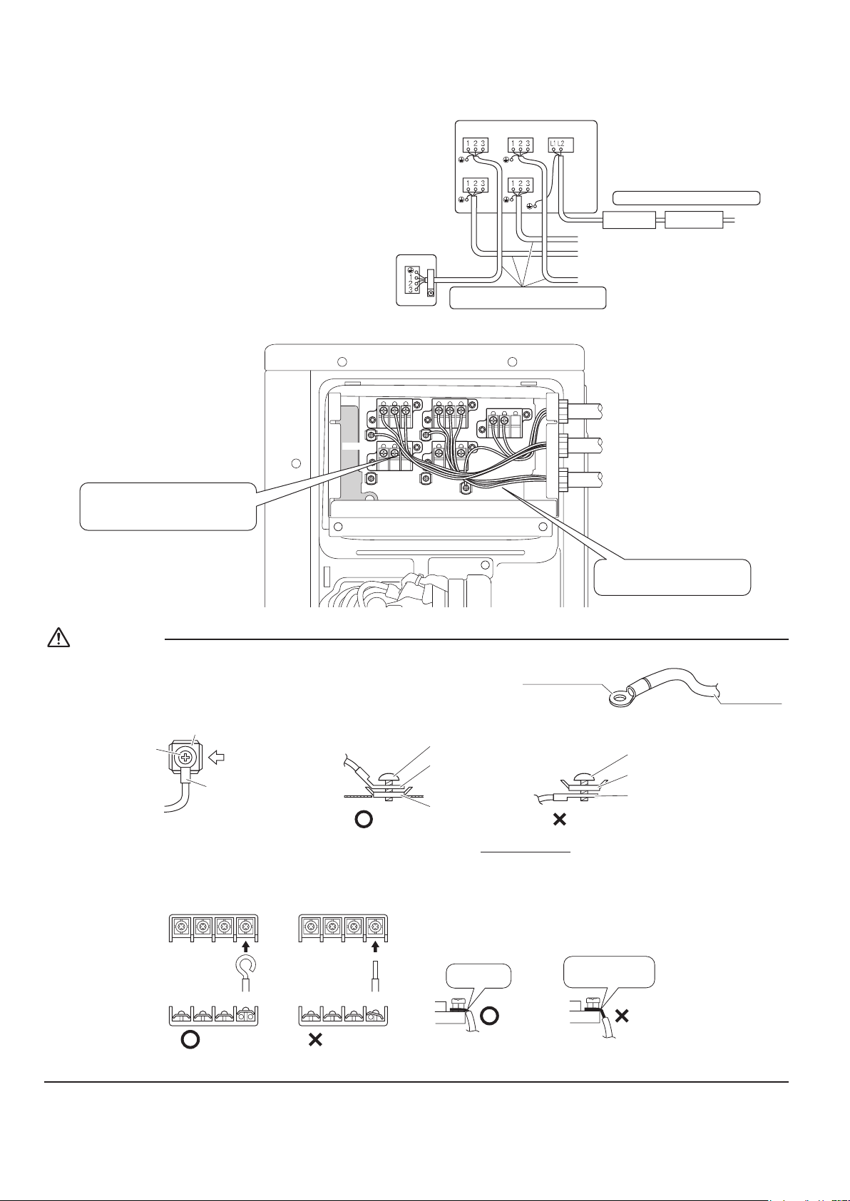
Wiring
[Wiring procedure]
1) Strip the insulation from the wire (3/4inch (20mm)).
2) Connect the inter-unit wires between the indoor and
outdoor units so that the terminal numbers match.
Tighten the terminal screws securely. It is recommended
thataatheadscrewdriverbeusedtotightenthescrews.
3) Be sure to match the symbols for wiring and piping.
4) Pull the wire lightly to make sure that it does not
disconnect.
5) Pass the wiring through the cutout on the bottom of the
protection plate and attach the protection plate.
6) After completing the work, reattach the service lid to its
original position.
Circuit breaker
Ground fault circuit
interrupter
Outdoor unit
60Hz 208/230V
Be sure to use the dedicated circuits.
To room B
To room C
To room D
Use AWG 16 or AWG 14 wire for
the power supply and inter-unit
wires.
Room
A
Room A
Room
C
Room
D
Room
B
Indoor unit
If the length of a connection wire
is 33ft (10m) or more, use AWG14 wire.
power supply
Shape the wires so that there is
no lifting of the service hatch or
other structural parts.
Use the specified wires and
connect them securely.
Room A
Room C
Room D
Room B
power supply
CAUTION
Precautions to be taken for power supply wiring
• When using stranded wires, make sure to use the round crimp-style
terminal for connection to the power supply terminal block.
Stranded
wire
Round crimp-style
terminal
Arrow view B
Flat washer
Screw
Round
crimp-style
terminal
Good
Round crimp-
style terminal
Flat washer
Screw
Wrong
Flat washer
Round crimp-
style terminal
Screw
B
Good
Round crimp-
style terminal
Flat washer
Screw
Wrong
Flat washer
Round crimp-
style terminal
Screw
Flat washer
Screw
Round
crimp-style
terminal
A
Arrow view A
• When connecting the inter-unit wires to the terminal block using a single core wire, be sure to curl the end of the lead.
Improperworkmaycauseheatandres.
Strip wire end
to this point.
Excessive strip length
may cause electric shock
or current leakage.
Stripping wire at terminal block
Good Wrong
Good Wrong
Ground
This air conditioner must be grounded. For grounding, follow all local, and state electrical codes.
01_EN_3P379970-8B.indd 13 11/17/2015 9:11:17
14■English
Priority Room Setting
• Tousepriorityroomsetting,initialsettingsmustbemadewhentheunitisinstalled.Explainthepriorityroomsetting,as
describedbelow,totheuser,andconrmwhetherornottheuserwantstousepriorityroomsetting.
Setting it in the guest and living rooms is convenient.
About the priority room setting function
The indoor unit for which priority room setting is applied takes priority in the following cases.
1) Operation mode priority
The operation mode of the indoor unit which is set for priority room setting
takes priority. If the set indoor unit is operating, all other indoor units do not
operate and enter standby mode, according to the operation mode of the
set indoor unit.
2) Priority during powerful operation
If the indoor unit which is set for priority room setting is operating at
powerful, the capabilities of other indoor units will be somewhat reduced.
Power supply gives priority to the indoor unit which is set for priority room
setting.
3) Quiet operation priority
Setting the indoor unit to quiet operation will make the outdoor unit run
quietly.
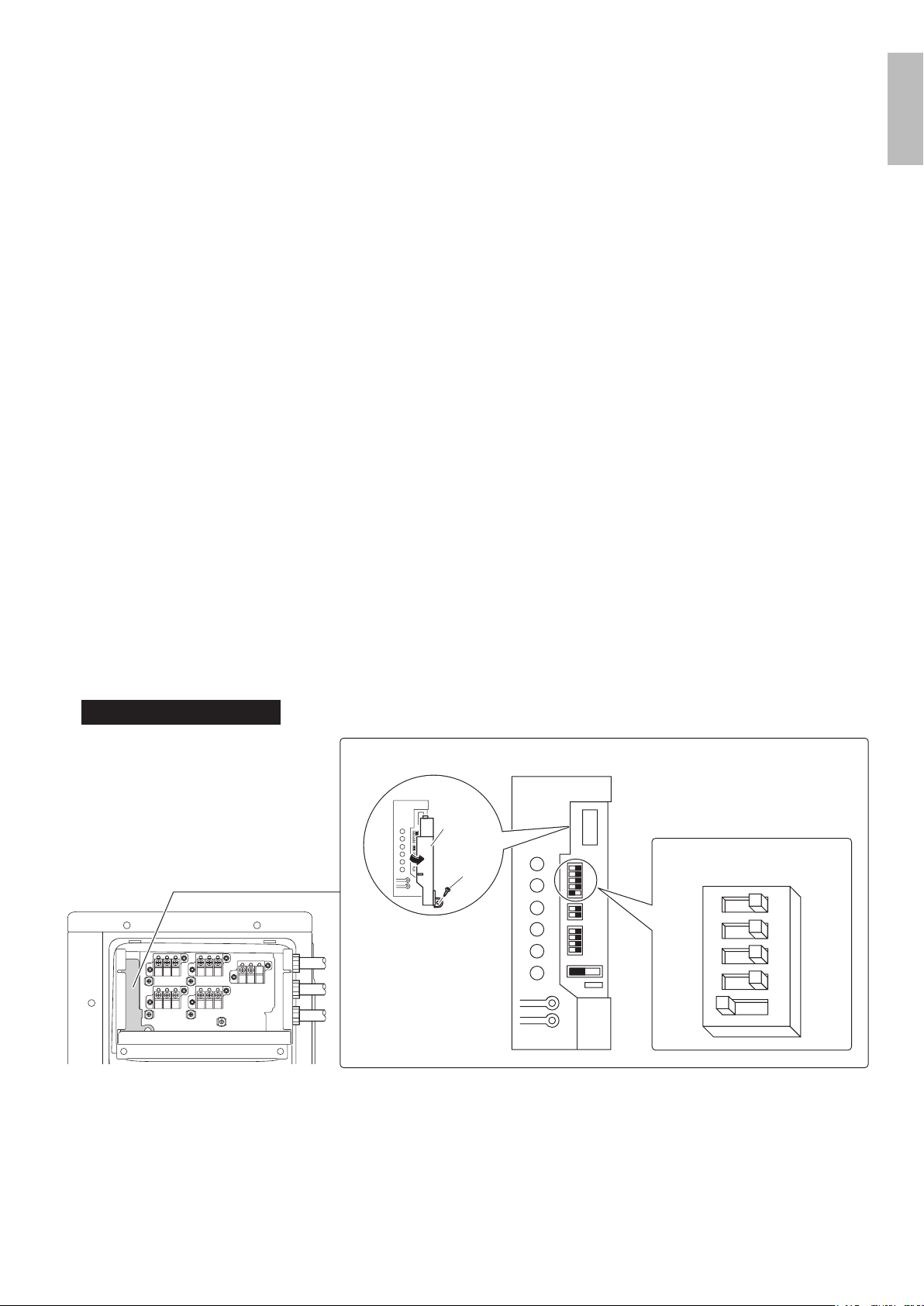
Setting procedure
Slide the priority room setting switch (SW4) to the on side for the switch that corresponds to the piping connected to the indoor
unit to be set.
(Inthegurebelow,itisroomA.)
Once the settings are complete, switch the power on.
Be sure to set only one room
Service PC-board
HEAT
COOL
4
3
2
1
2
1
E
D
C
B
A
COOL
4
3
2
1
2
1
E
D
C
B
A
Screw
Remove
the switch
cover
Priority room setting switch (SW4)
ON OFF
E
D
C
B
A
English
01_EN_3P379970-8B.indd 14 11/17/2015 9:11:17
15 ■English
Night Quiet Mode setting
• Ifnightquietmodeistobeused,initialsettingsmustbemadewhentheunitisinstalled.Explainnightquietmode,asdescribed
below,totheuser,andconrmwhetherornottheuserwantstousenightquietmode.
About night quiet mode
The night quiet mode function reduces operating noise of the outdoor unit at nighttime. This function is useful if the user is
worried about the effects of the operating noise on the neighbors.
However, if night quiet mode is running, cooling capacity will be saved.
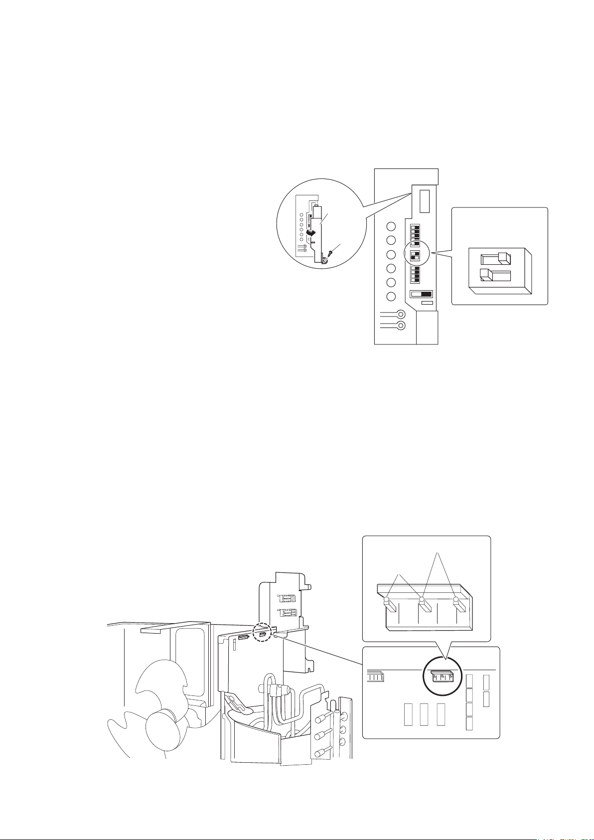
Setting procedure
Turn the night quiet mode switch (SW6-1) to on.
COOL/ HEAT mode lock [S15]
• Use the S15 connector to set the unit to only cool or heat.
Setting to only heat (H) : short-circuit pins 1 and 3 of the connector [S15]
Setting to only cool (C) : short-circuit pins 3 and 5 of the connector [S15]
Thefollowingspecicationsapplytotheconnectorhousingandpins.
JST products Housing: VHR-5N
Pin: SVH-21T-1,1
NotethatforcedoperationisalsopossibleinCOOL/HEATmode.
COOL mode (C)
HEAT mode (H)
13 5
Service PC-board
HEAT
COOL
4
3
2
1
2
1
E
D
C
B
A
COOL
4
3
2
1
2
1
E
D
C
B
A
Screw
Remove
the switch
cover
Night quiet mode
setting switch
(SW6-1)
2
1
ON OFF
01_EN_3P379970-8B.indd 15 11/17/2015 9:11:17

16■English
Pump Down Operation
In order to protect the environment, be sure to pump down when relocating or disposing of the unit.
1) Remove the valve cap from liquid stop valve and gas stop valve.
2) Carry out forced cooling operation.
3) After5to10minutes,closetheliquidstopvalvewithahexagonal
wrench.
4) After 2 to 3 minutes, close the gas stop valve and stop forced
cooling operation.
Gas stop valve
Close
Hexagonal
wrench
Liquid stop
valve
Valve cap
Forced cooling operation
1) Turn off the power.
2) Remove the service lid (2 screws).
3) Remove the service PC-board switch cover (1 screw).
4) Switch SW5 and SW6 to off.
5) Turn the operation mode switch (SW2) to COOL.
6) Screw the service PC-board switch cover back on (1 screw).
7) Turn on the power.
8) Push the forced operation switch (SW1) above the service PC-board cover. (The operation will start.)
• Forced cooling operation will stop automatically after about 10 minutes.
To stop the operation, push the forced operation switch (SW1).
Service PC-board
HEAT
COOL
4
3
2
1
2
1
E
D
C
B
A
COOL
4
3
2
1
2
1
E
D
C
B
A
Screw
Remove
the switch
cover
Forced operation switch (SW1)
•Switch SW5 and SW6 to off.
•Set to COOL.
Operation mode switch (SW2)
2
1
ON OFF
4
3
ON OFF
2
1
HEAT
COOL
SW6
SW5
WARNING
Do not remove the switch cover unless the power has been turned off. (Risk of electric shock)
English
01_EN_3P379970-8B.indd 16 11/17/2015 9:11:18
17 ■English
Trial Operation and Testing
• Before starting the trial operation, measure the voltage at the primary side of the circuit breaker.
• Check that all liquid and gas stop valves are fully open.
• Check that piping and wiring all match. The wiring error check can be conveniently used for underground wiring and other wiring
that cannot be directly checked. However, if the outside air temperature is
41°F(5°C)orless , the wiring error check function
will not operate.
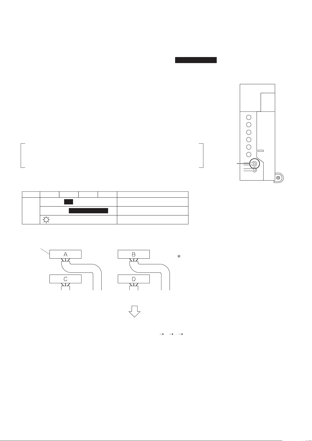
1. Wiring error check
This product is capable of automatic correction of wiring errors.
Press the wiring error check switch on the outdoor unit service PC-board for about
3seconds.However,thewiringerrorcheckswitchwillnotfunctionfor3minutesafterthe
safety breaker is turned on. About 15-20 minutes after the switch is pressed, the errors in
the connection wiring will be corrected.
TheservicemonitorLEDsindicatewhetherornotcorrectionispossible,as
showninthetablebelow.FordetailsonhowtoreadtheLEDdisplay,referto
the collective indications label on the reverse side of the top plate or the service
manual.
If self-correction is not possible, check the indoor unit wiring and piping in the usual
manner.
Service PC-board
A
1
2
3
4
5
Wiring error
check switch
(SW3)
LED
Status
1 2 3 4
All Flashing
Automatic correction impossible
Automatic correction completed
Abnormal stop [Note. 3]
Message
Flashing One after another
(One or more of LEDs 1 to 4 are ON)
Terminal block
Wiring error check
LED lighting sequence after a wiring correction.
Order of LED flashing: 2
1 3 4
From Room C
to the “kitchen”
From Room B
to the “living room”
From Room D
to the “children’s room”
From Room A
to the “bedroom”
Wiring correct example
The figure at left shows branch wiring.
NOTE
1) Fortworooms,LED3,4and5arenotdisplayed,andforthreerooms,LED4and5isnotdisplayed,andforfourrooms,
LED5isnotdisplayed.
2) Afterwiringerrorcheckoperationiscompleted,LEDindicationwillcontinueuntilordinaryoperationstarts.Thisisnormal.
3) Follow the product diagnosis procedures. (Details of product error diagnosis are listed on the reverse side of the top plate.)
01_EN_3P379970-8B.indd 17 11/17/2015 9:11:18
18■English
2. Trial operation and testing
• Duringthetrialoperation,rstchecktheoperationofeachunitindividually.Afterthis,checkthesimultaneousoperationof
allindoorunits.CheckbothCOOLandHEAToperations.
2-1. Measure the supply voltage and make sure that it is within the specied range.
2-2. In COOL operation, select the lowest programmable temperature;
in HEAT operation, select the highest programmable temperature.
2-3. Carry out the trial operation following the instructions in the operation manual to
ensure that all functions and parts, such as the movement of the ap, are working
properly.
• To protect the air conditioner, restart operation is disabled for 3 minutes after the system has been turned off.
• WhentrialoperationisconductedinHEAToperationdirectlyafterthecircuitbreakeristurnedon,insomecasesno
air will be output for about 3 to 20 minutes in order to protect the air conditioner.
• During COOL operation, frost may form on the gas stop valve or other parts. This is normal.
2-4. After running the unit for about 20 minutes, measure the temperatures at the
indoor unit inlet and outlet.
• If the measurements are above the values shown in the table below, then they are normal.
COOL operation HEAToperation
Temperature difference between
inlet and outlet
About14°F(8°C) About36°F(20°C)
(When running in one room)
2-5. After trial operation is complete, set the temperature to a normal level (78°F
to 82°F (26°C to 28°C) in COOL operation, 68°F to 75°F (20°C to 24°C) in HEAT
operation).
• WhenoperatingtheairconditionerinCOOLoperationinwinter,orHEAToperationinsummer,activatetrialoperation
mode by following the instructions in the installation manual for the indoor unit.
• The air conditioner draws a small amount of power in its standby mode. If the system is not to be used for some time after
installation, shut off the circuit breaker to eliminate unnecessary power consumption.
• If the circuit breaker trips to shut off the power to the air conditioner, the system will restore the original operation mode
when the circuit breaker is opened again.
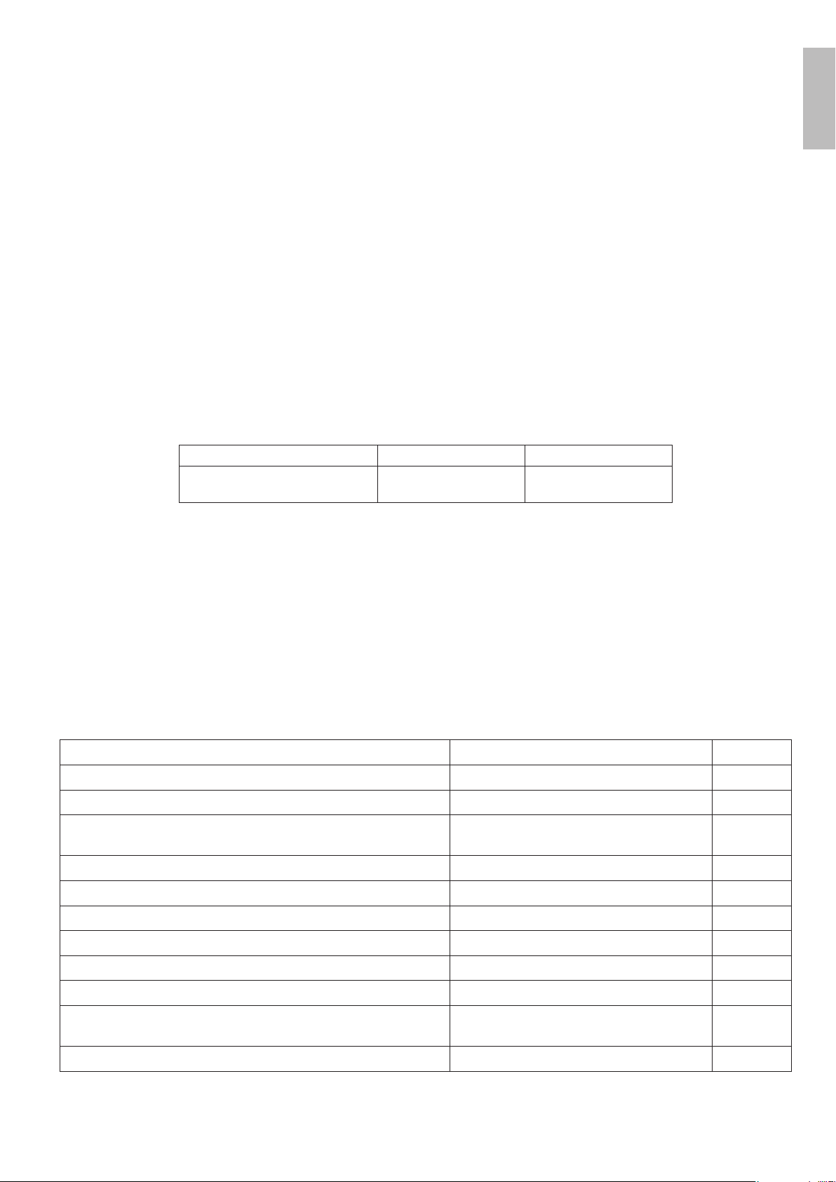
3. Test items
Test item Symptom Check
Indoor and outdoor units are installed properly on solid bases. Fall, vibration, noise
No refrigerant gas leaks. Incomplete cooling/heating function
Refrigerantgasandliquidpipesandindoordrainhoseextension
are thermally insulated.
Water leakage
Draining line is properly installed. Water leakage
System is properly grounded. Electricalleakage
The electric wires are connected correctly. Incomplete cooling/heating function
Thespeciedwiresareusedforinter-unitwiring. No operation or burn damage
Indoor or outdoor unit’s air inlet or air outlet are unobstructed. Incomplete cooling/heating function
Stop valves are opened. Incomplete cooling/heating function
The wiring and piping marks for each indoor unit (room A, room B,
room C, and room D) match.
Incomplete cooling/heating function
The priority room setting is set for only 1 room. The priority room setting will not function.
English
01_EN_3P379970-8B.indd 18 11/17/2015 9:11:18

Two-dimensional bar code
is a manufacturing code.
3P379970-8B
M15B137
(1511)
HT
00_CV_3P379970-8B.indd 2 11/4/2015 15:32:58
