Loading ...
Loading ...
Loading ...
PAGE: 6 / 9
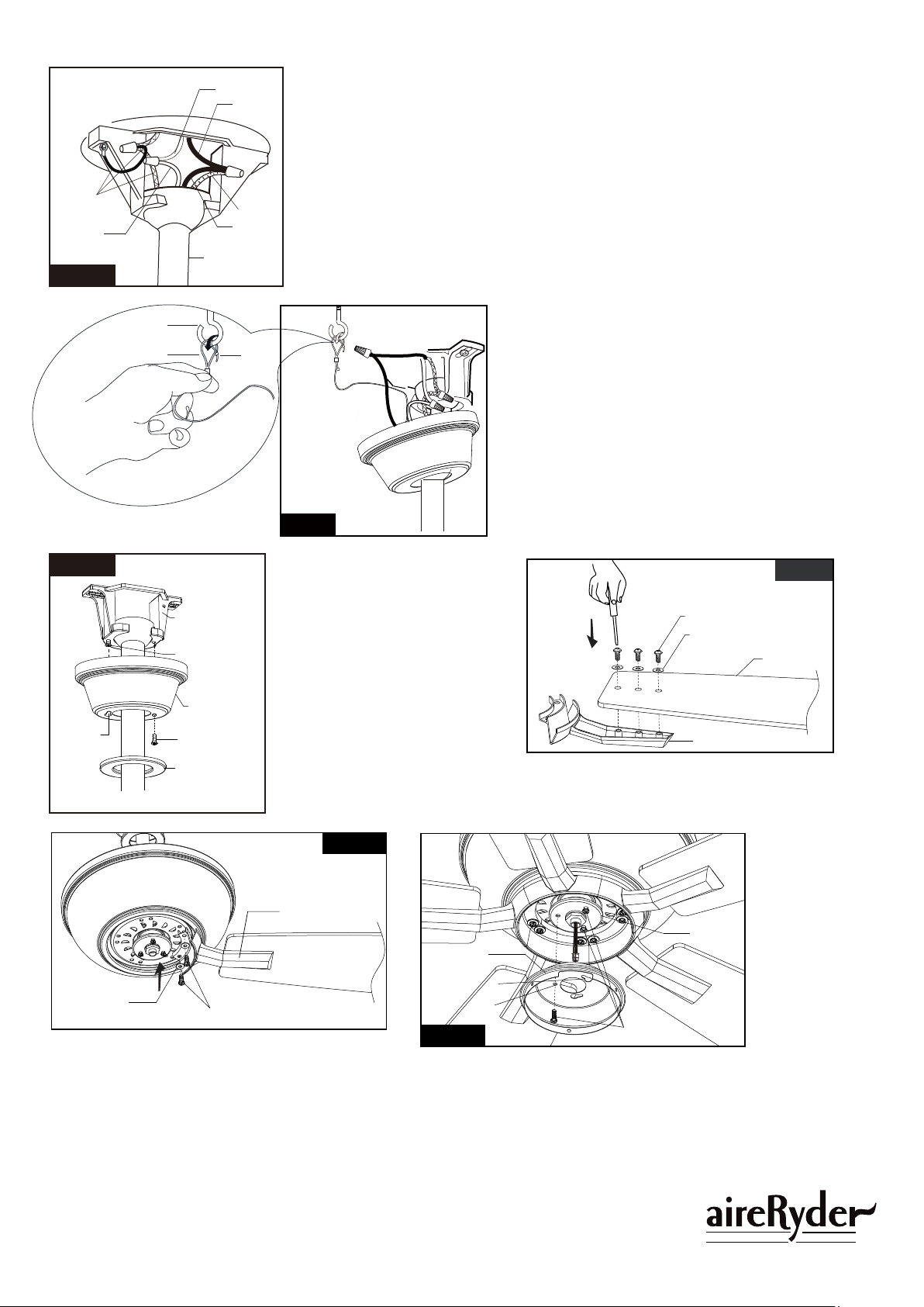
Blue
Black
Downrod
White
White
Ground
Wire
Fig.8
Fig.10
Make wire connections:
1). The white motor wire to the white wire from the outlet box with a wire connector.
2). The black motor wire and blue wire to the black (hot) wire from the outlet box
with a wire connector.
3). The ground wires from the downrod and the hanger bracket to the ground wire
from the outlet box with a wire connector.
*** After making the wire connections, the wires should be spread apart with the
grounded wires on one side of the outlet box and the ungrounded wires on the
other side of the outlet box.
*** After the connections have been made, the wires should be turned upward and
pushed carefully up into the outlet box.
Black
Blade Bracket
Motor Screw
Remove the motor screws and washers from the
motor assembly.
Secure Blade Brackets to the motor with washers
and motor screws.
Fan Blade
Washer
Switch Box
Cover
Key Hole Slot
Round Hole
Fix Screw
Motor
Assembly
Washer
F A N C O
180725
Fig.11
Fig.12
Fig.13
Tighten fan blades to blade brackets by using
washers and blade screws.
Blade Screw
Blade Bracket
Canopy Screw
Canopy Screw
Key Hole
Slot
Hanger Bracket
Canopy
Decorative Cap
Remove one canopy screw (for
later use), then push the canopy
upwards by inserting canopy
screw head left in hanger bracket
into key hole slot, rotate the
canopy till the hole in canopy aligns
the hole in hanger bracket, finally,
secure the canopy to hanger
bracket with previous canopy
screw and tighten the other canopy
screw.
Attach the decorative cap to
canopy,rotate it clockwise until
tight.
Remove one fix screw (for later use), and loosen the other two
fix screws. Thread the wire through the switch box cover, and
then push the switch box cover upwards by inserting the other
two fix screw heads into key hole slots, rotate the switch box
cover till the round hole in switch box cover aligns the hole in
motor assembly, finally, secure the switch box cover to motor
assembly with previous fix screw and tighten the other two fix
screws.
Fig.9
Safety Cable Hook
Safety Cable
Zip-tie
Hang the safety cable into the safety cable hook,
tighten the safety cable to the safety cable hook
by using the zip-tie.
Loading ...
Loading ...
Loading ...