Loading ...
Loading ...
Loading ...
Section 4 - ADJUSTMENTS & REPAIR
WARNING
DO NOT attempt any adjustments, maintenance,
service or repairs with the engine running. Stop
engine. Stop blade. Engage parking brake. Remove
key. Remove spark plug wire from spark plug and
secure away from plug. Engine and components are
HOT. Avoid serious burns, allow all parts to cool
before working on machine. Fuel Filler Cap and Vent
must be closed securely to prevent fuel spillage. DO
NOT use a cutting blade that shows signs of
excessive wear or damage. On Rear Engine Riders
5. Inspect condition of blade. See Figure 4.11.
6. If blade is in good condition, sharpen at 22 to 28
degrees. DO NOT sharpen beyond existing cutting
edge. See Figure 4.13.
7. Check blade balance after sharpening. If
necessary, correct blade balance by grinding the
heavy end of blade.
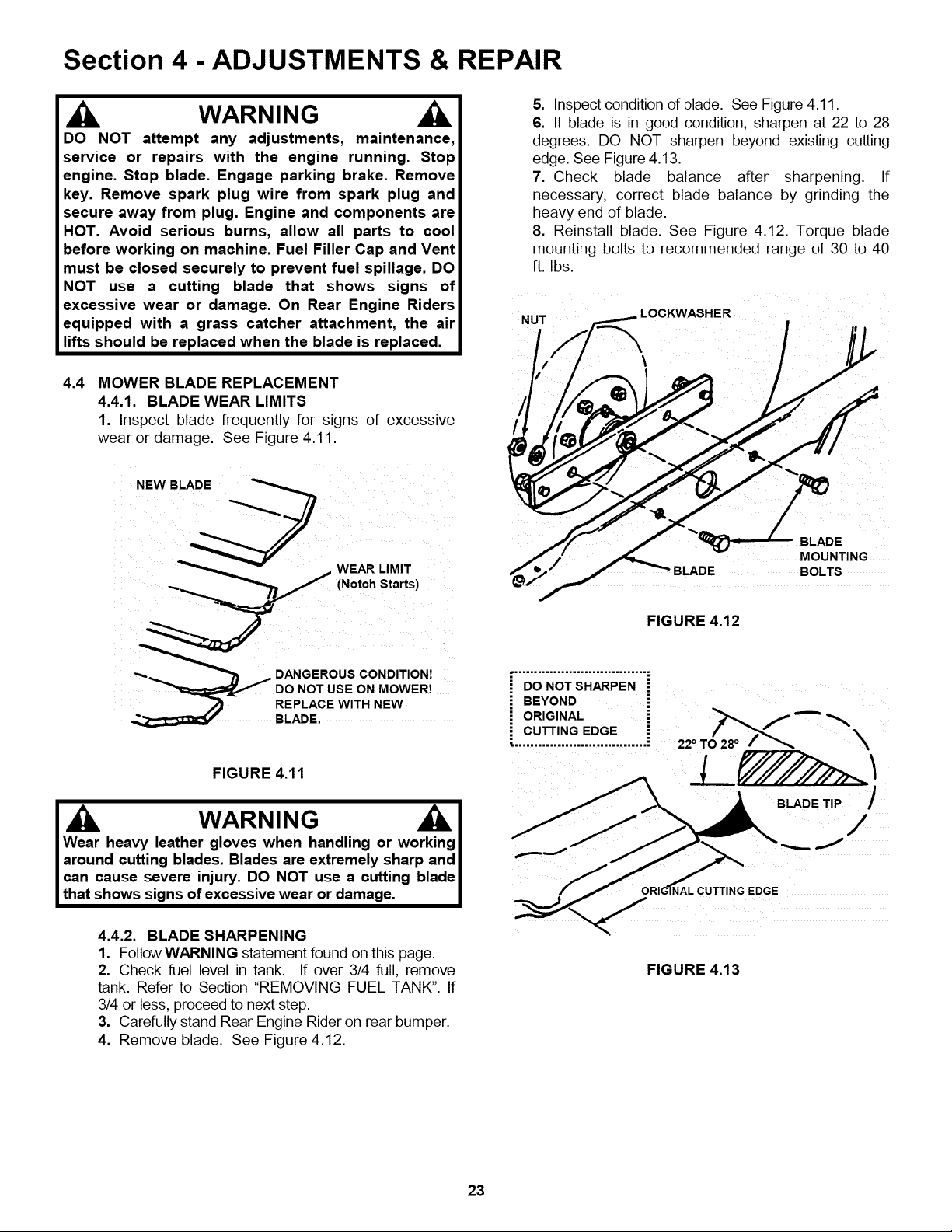
8. Reinstall blade. See Figure 4.12. Torque blade
mounting bolts to recommended range of 30 to 40
ft. Ibs.
LOCKWASHER
equipped with a grass catcher attachment, the air
lifts should be replaced when the blade is replaced.
4.4
/ b
MOWER BLADE REPLACEMENT
4.4.1. BLADE WEAR LIMITS
1. Inspect blade frequently for signs of excessive
wear or damage. See Figure 4.11.
NEW BLADE
@
BLADE BOLTS
FIGURE 4.12
"_.= _ DANGEROUS CONDITION!
ooNO,oooONoowo ,
HARPEN
REPLACE WITH NEW
BLADE.
FIGURE 4.11
WARNING AI
Wear heavy leather gloves when handling or working I
around cutting blades. Blades are extremely sharp and
can cause severe injury. DO NOT use a cutting blade l
that shows signs of excessive wear or damage. I
CUTTING EDGE O/28o /_,,,_ -'-"
• .................................. ; 22 ° T X
BLADE TiP /
/
qAL CUTTING EDGE
4.4.2. BLADE SHARPENING
1. Follow WARNING statement found on this page.
2. Check fuel level in tank. If over 3/4 full, remove
tank. Refer to Section "REMOVING FUEL TANK". If
3/4 or less, proceed to next step.
3. Carefully stand Rear Engine Rider on rear bumper.
4. Remove blade. See Figure 4.12.
FIGURE 4.13
23
Loading ...
Loading ...
Loading ...