Loading ...
Loading ...
3
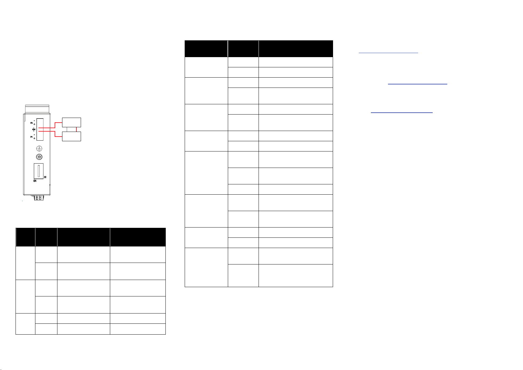
Alarm Relay Connecting (for Non-PoE Models)
The alarm relay output contacts are in the middle of the DC
terminal block connector shown as the figure below.
By inserting the wires and set the DIP switch of the
respective Port Alarm to “ON”, the relay output alarm will
detect any port failures, and form a short circuit.
The alarm relay out is “Normal Open”.
Alarm
system
Extra power
system
Maximum 1A / DC 24V
DIP Switch Setting
LED STATUS INDICATIONS
LED Name Indicator/
color
Condition
PoE
On Green PoE is working.
Off PoE is not working
P1
On Green P1 power line has power
Off P1 power line disconnect or
does not have supply power
P2
On Green P2 power line has power
Off P2 power line disconnect or
does not have supply power
ALM
On Red Power failure alarm occurs
Off No power failure alarm
Copper 1 to N
port Link/Act
On Green Ethernet link up but no traffic is
detected
Blinking
Green
Ethernet link up and there is
traffic detected
Off Ethernet link down
Copper 1 to N
port Speed
On Yellow A 1000Mbps connection is
detected
Off No link, a 10Mbps or 100
Mbps connection is detected
SFP 1 to N port
(N=0,1,2)
Link/Act
On Green Ethernet link up
Off Ethernet link down
SFP 1 to N port
(N=0,1,2) Speed
On Yellow SFP port speed 1000Mbps
connection is detected.
Off No link or a SFP port speed
100Mbps connection is
detected
Additional Information
You can refer to the user manual or visit
http://support.dlink.com/
for more support.
Online Support
If there are any issues that are not in the user manual,
please visit http://support.dlink.com/
which will direct you to
your appropriate local D-Link support website.
Warranty Information
Visit http://warranty.dlink.com/ to view the D-Link Warranty
information.
Pin
No#
Status
DIS-100G-5S
DIS-100G-5SW
DIS-100G-5PSW
Pin 1
ON
To enable the power
alarm.
To enable Broadcast
storm rate limit.
OFF
To disable the power
alarm.
To disable Broadcast
storm rate limit
Pin 2
ON
To enable Broadcast
storm rate limit
NOT USED
OFF
To disable Broadcast
storm rate limit
NOT USED
Pin 3-6
ON NOT USED NOT USED
OFF NOT USED NOT USED
Loading ...