
OPERATOR'S MANUAL
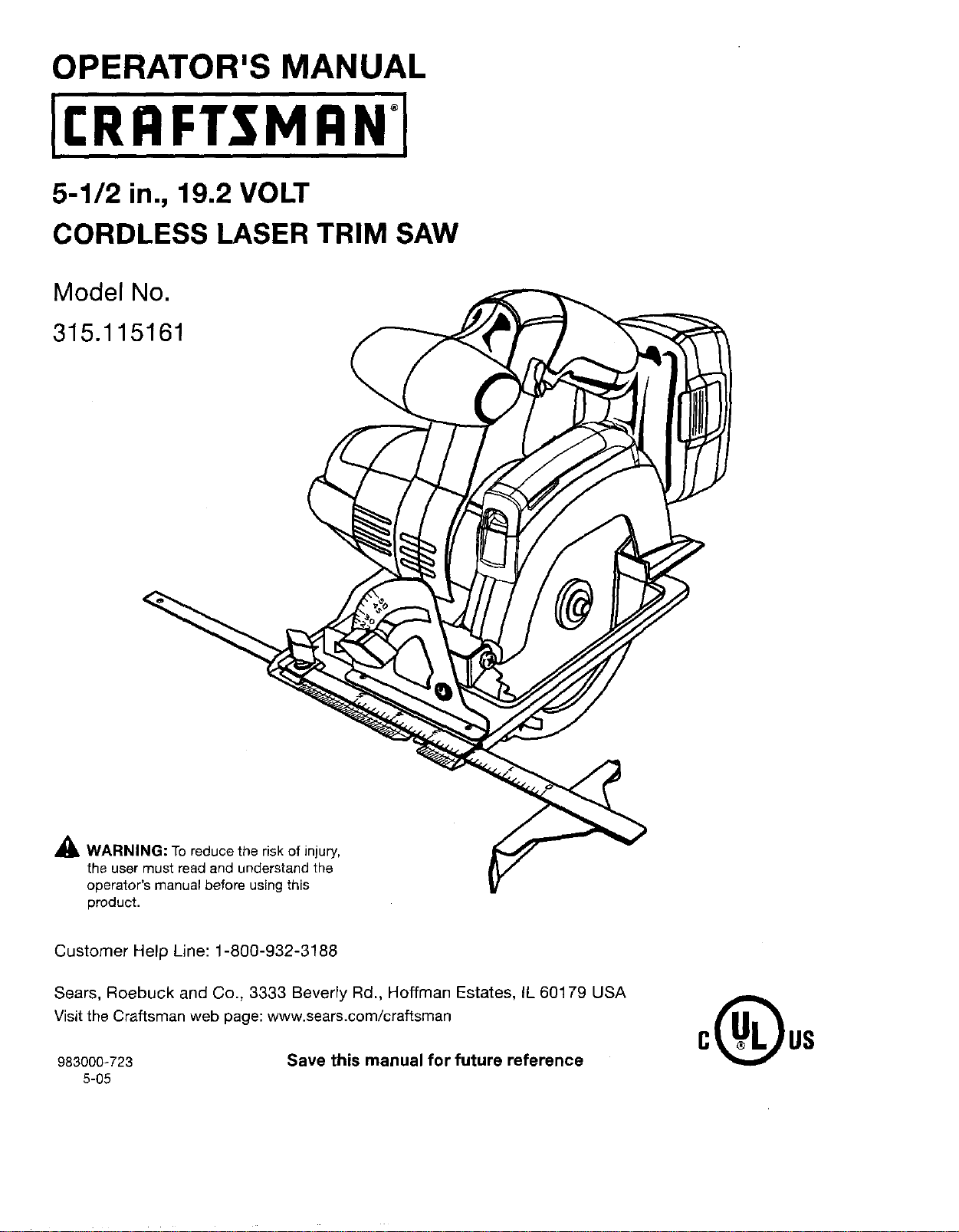
5-1/2 in., 19.2 VOLT
CORDLESS LASER TRIM SAW
Model No.
315.115161
_IL WARNING: To reduce the risk of injury,
the user must read and understand the
operator's manual before using this
product.
Customer Help Line: 1-800-932-3188
Sears, Roebuck and Co., 3333 Beverly Rd., Hoffman Estates, IL 60179 USA
Visit the Craftsman web page: www.sears.com/craftsman
983000-723 Save this manual for future reference
5-05
• Warranty...........................................................................................................................................................................2
• Introduction......................................................................................................................................................................2
• General Safety Rules..................................................................................................................................................... 3-4
• Specific Safety Rules..................................................................................................................................................... 4-6
• Safety Rules for Charger .................................................................................................................................................. 7
• Symbots ......................................................................................................................................................................... 8-9
• Features..................................................................................................................................................................... 10-11
• Assembly ................................................................................................................................................................... 11-13
• Operation................................................................................................................................................................... 14-24
• Adjustments.................................................................................................................................................................... 24
• Maintenance .............................................................................................................................................................. 25-26
• Accessories .................................................................................................................................................................... 26
• Exploded View and Repair Parts List ........................................................................................................................ 27-28
• Parts Ordering/Service .................................................................................................................................... Back Page
ONE YEAR FULLWARRANTY ON CRAFTSMAN TOOL
IfthisCraftsman tooltailsto givecompletesatisfactionwithinoneyearfrom date ofpurchase,RETURN IT TO THE
NEAREST SEARS STORE OR SEARS PARTS& REPAIR CENTER IN THE UNITED STATES,and Sears willrepairit,
free of charge.
If this Craftsman tool is used for commercial or rental purposes, this warranty applies for only 90 days from the date of
purchase.
This warranty gives you specific legal rights, and you may also have other rights which vary from state to state.
Sears, Roebuck and Co., Dept. 817WA, Hoffman Estates, IL 60179
This tool has many features for making its use more pleasant and enjoyable. Safety, performance, and dependability
have been given top priority in the design of this product making it easy to maintain and operate.
2
WARNING! READ AND UNDERSTAND ALL IN-
STRUCTIONS. Failureto follow all instructions listed
below, may result in electric shock, fire and/or seri-
ous personar injury.
SAVE THESE INSTRUCTIONS
WORK AREA
• Keep your work area clean and well lit. Cluttered
benches and dark areas invite accidents.
• Do not operate power tools in explosive atmo-
spheres, such as in the presence of flammable liq-
uids, gases, or dust. Powertoolscreatesparks which
may ignite the dust or fumes.
• Keep bystanders, children, and visitors away while
operating a power tool. Distractions can cause you to
lose control.
ELECTRICAL SAFETY
• A battery operated tool with integral batteries or a
separate battery pack must be recharged only with
the specified charger for the battery. A chargerthat
may be suitable for one type ofbattery may create a
risk of fire when used with another battery.
• Use battery operated tool onlywith specifically des-
ignated battery pack. Use ofanyotherbatteries may
create a risk of fire.
• Use battery only with charger listed.
MODEL BATTERYPACK
315.115161 130279003
130279005
(item No.-9!1375)
CHARGER
Model No. 1425301
(Item No. _911041)
Model No. 315.115730
(Item No. 140301003)
Model No. 315.115720
(Item No. 140301001)
• Do not abuse the cord. Never use the cord to carry
the charger. Keep cord away from heat, oil, sharp
edges, or moving parts. Replace damaged cords
immediately. Damaged cords may create a fire.
PERSONAL SAFETY
• Stay alert, watch what you are doing and usecom-
mon sense when operating a power tool. Do not
use tool while tired or under the influence of drugs,
alcohol, or medication. A moment of inattentionwhile
operatingpower toolsmay result inseriouspersonar
injury.
• Dress properly. Do not wear loose clothing or
jewelry. Contain long hair. Keep your hair, clothing,
and gloves away from moving parts. Looseclothes,
jeweJry, or long hair can be caught in moving parts.
• Avoid accidental starting. Be sure switch isin the
locked or off position before inserting battery pack.
Carrying tools with your finger on the switch or insert-
ing the battery pack into a tool with the switch on
invites accidents.
• Remove adjusting keys orwrenches before turning
the tool on. A wrenchora keythat isleftattached toa
rotating part of thetool may resultinpersonar injury.
• Do not overreach. Keep proper footing and balance
at all times. Properfooting and balance enablebetter
control of the tool in unexpected situations.
• Use safety equipment. Always wear eye protection.
Dust mask, non-skid safety shoes, hard hat, or hearing
protection must be used for appropriate conditions.
• Do not wear loose clothing or jewelry. Contain long
hair. Loose clothes, jewelry, or long hair can be drawn
into air vents.
• Do not use on a ladder or unstable support. Stable
footing on a solid surface enables better control of the
tool in unexpected situations.
TOOL USE AND CARE
• Use clamps or other practical way to secure and
support the workpiece to a stable platform. Holding
the work by handor againstyour body isunstableand
may lead to lossofcontrol.
• Do not force tool. Use the correct tool for your ap-
plication. The correct tool will do the iob better and
safer at the rate for which it is designed.
• Do not usetool if switch does not turn it on or off.
A tool that cannot be controlled with the switch is dan-
gerous and must be repaired.
• Disconnect battery pack from tool or place the
switch in the locked or off position before making
any adjustments, changing accessories, or storing
the tool. Such preventive safety measures reduce the
risk of starting the tool accidentally.
• Store idle tools out of reach of children and other
untrained persons. Tools aredangerousinthe hands
of untrainedusers.
• When battery pack is not in use, keep it away from
other metal objects like: paper clips, coins, keys,
nails, screws, or other small metal objects that can
make a connection from one terminal to another.
Shorting the battery terminals together may cause
sparks, burns, or a fire.
• Maintain tools with care. Keep cutting tools sharp
and clean. Properly maintained tools with sharp cut-
ting edges are less likely to bind and are easier to
control,
• Check for misalignment or binding of moving parts,
breakage of parts, and anyother condition that
may affect the tool's operation. If damaged, have
the tool serviced before using.Many accidentsare
caused by poorly maintained tools.
• Use only accessories that are recommended by the
manufacturer for your model. Accessories that may
be suitable for one toolmay create a risk of injurywhen
usedon anothertool.
• Keep the tool and its handle dry, clean and free
from oiland grease. Always use a cleanclothwhen
cleaning.Never usebrake fluids, gasoline,petroleum-
based products,or anystrong solvents to cleanyour
tool. Followingthisrule will reducethe risk of loss of
controland deterioration of theenclosureplastic.

• Useonlyaccessoriesthatarerecommendedbythe
manufacturerfor your model. Accessoriesthatmay
besuitable for onetool may create a riskof injurywhen
used on another tool.
• Keep the tool and its handle dry, clean and free
from oil and grease. Always use a clean cloth when
cleaning. Never use brake fluids, gasoline, petroleum-
based products, or any strong solvents to clean your
tool. Following this rule will reduce the risk of loss of
control and deterioration of the enclosure plastic.
SERVICE
II Tool service must be performed only byqualified
repair personnel. Service or maintenance performed
by unqualified personnel may result in a risk of injury.
• When servicinga tool, use only identical replace-
ment parts. Follow instructions in the Maintenance
section of this manual. Useof unauthorized partsor
failure tofollow Maintenanceinstructions may createa
risk of shock or injury.
• Hold power tool by insulated gripping surfaces
when performing an operation where the cutting
tool may contact hidden wiring. Contact with a "live"
wirewill also make exposedmetal parts ofthe tool
"live" and shock the operator.
• DANGER! Keep hands away from cutting area and
blade. Keep your second hand on auxiliary handle
or motor housing, if both handsare holdingthe saw,
they cannot be cut by the blade.
• Keep your body positioned to either side of the saw
blade, but not in line with the saw blade. KICKBACK
could cause the saw to jump backwards. (see KICK-
BACK)
• Do not reach underneath the work. The guard can-
not protect you from the blade below the work.
• Check the lower guard for proper closing before
each use. Do not operate saw if lower guard does
not move freely and close instantly. Never clamp or
tie the lower guard intothe open position, ifsawis
accidentally dropped, lower guard may be bent. Raise
the lower guard with the retracting handle and make
sure it moves freely and does not touch the blade or
any other part, inall angles and depths of cut.
• Check the operation and condition ofthe lower
guard spring. If the guard and the spring are not
operating properly, they must be serviced before
use. Lower guard may operate sluggishly due to dam-
aged parts, gummy deposits, or a buildup of debris.
• Lower guard should be retracted manually only
for special cuts such as "Pocket Cuts" and "Com-
pound Cuts". Raise lower guard by Retracting
Handle. As soon as blade enters the material, lower
guard must be released. Forall othersawing,the
lower guard should operate automatically.
• Always observe that the lower guard is covering the
blade before placing saw down on bench or floor.
An unprotected, coasting blade will cause the saw to
walk backwards, cutting whatever is in its path. Be
aware of the time it takes for the blade to stop after
switch is released.
• NEVER hold piece being cut in your handsor
across your leg. It isimportantto support the work
properlyto minimize bodyexposure,blade binding, or
loss of control.
• Hold tool by insulated gripping surfaces when
performing an operation where the cutting tool may
contact hiddenwiring, Contact with a "live" wire will
also make exposed metal parts of the tool "live" and
shock the operator.
• When ripping always use a rip fence or straight
edge guide. This improves the accuracy of cut and
reduces the chance of blade binding.
• Always use blades with correct size and shape
(diamond vs. round) arbor holes. Bladesthatdo not
matchthemounting hardware of thesaw willrun ec-
centrically, causing loss of control.
• Never use damaged or incorrect blade washers
or bolts. The bladewashers and bolt were specially
designed for your saw, for optimum performance and
safety of operation.
Causes and Operator Prevention of Kickback:
Kickback is a sudden reaction to a pinched, bound, or
misaligned saw blade, causing an uncontrolled saw to
lift up and out of the workpiece toward the operator.
When the blade is pinched or bound tightly by the kerf
closing down, the blade stalls and the motor reaction
drives the unit rapidly back toward the operator.
If the blade becomes twisted or misaligned in the cut,
the teeth at the back edge of the blade can dig into the
top surface of the wood causing the blade to climb out
of the kerf andjump back toward the operator.
Kickback is a result of tool misuse and/or incorrect op-
erating procedures or conditions and can be avoided by
taking proper precautions as given below:
• Maintain a firm grip on the saw and position your
body and arm in a way that allows you to resist
KICKBACK forces. KICKBACKforces can be con-
trolledby the operator,ifproper precautions are taken.
• When blade isbinding, or when interrupting a cut
for any reason, release the trigger and hold the saw
motionless in the material until the blade comes to
a complete stop. Never attempt to remove the saw
from the work or pull the saw backward while the
blade is in motion or KICKBACK may occur. Investi-
gate and take corrective actions to eliminate the cause
of-blade binding.
• When restarting a saw in the workpiece, center the
saw blade in the ken' and check that teeth are not
engaged into the material, if saw blade is binding, it
may walk up or KICKBACK from the workpiece asthe
saw is restarted.
• Support large panels to minimize the risk of blade
pinching and KICKBACK. Large panels tend to sag
under their ownweight. Supports must be placed
under the panel on both sides, near the lineof cut and
near the edge of the panel.
• Do not use dull or damaged blade. Unsharpened or
improperly set blades produce narrow kerf causing
excessive friction, blade binding, and KICKBACK.
• Blade depth and bevel adjusting locking levers
must be tight end secure before making cut. If blade
adjustment shifts while cutting, itwill cause binding
and KICKBACK.
• Use extra caution when making a "Pocket Cut" into
existing walls or other blind areas. The protruding
blade may cut objects that can cause KICKBACK.
Laser Guide Warnings:
The laserguide radiation used inthe Craftsman trim saw is
Class Iliawith maximum <5mW and 650nm wavelengths or
ClassIlwithmaximum<1 mWand650nmwavelengths.These
lasers do not normally present an optical hazard although
staring at the beam may cause flash blindness.
• Avoid direct eye exposure when using the laser guide.
• The laser shaJfbe used and maintained in accordance
with the manufacturer's instructions.
Never aim the beam at a person or object other than
the workpiece.
Always ensure the laser beam is aimed at a sturdy
workpiece without reflective surfaces. Shiny reflective
sheet metal or similar shiny materials are not suitable
for laser use.
• All repairs should be made by an authorized service
representative or the laser manufacturer.
Additional Rules for Safe Operation:
• Know your power tool. Read operator's manual
carefully. Learn itsapplications and limitations, as
well as the specific potential hazards related to this
power tool. Followingthis rule willreduce the risk of
electricshock, fire, or serious injury.
• Always wear safety glasses with side shields.
Everyday glasses have only impact resistant lenses.
They are NOT safety glasses. Following this rule will
reduce the risk of eye injury.
• Protect your lungs. Wear a face or dust mask ifthe
operation is dusty. Followingthis rule will reduce the
riskofseriouspersonalinjury.
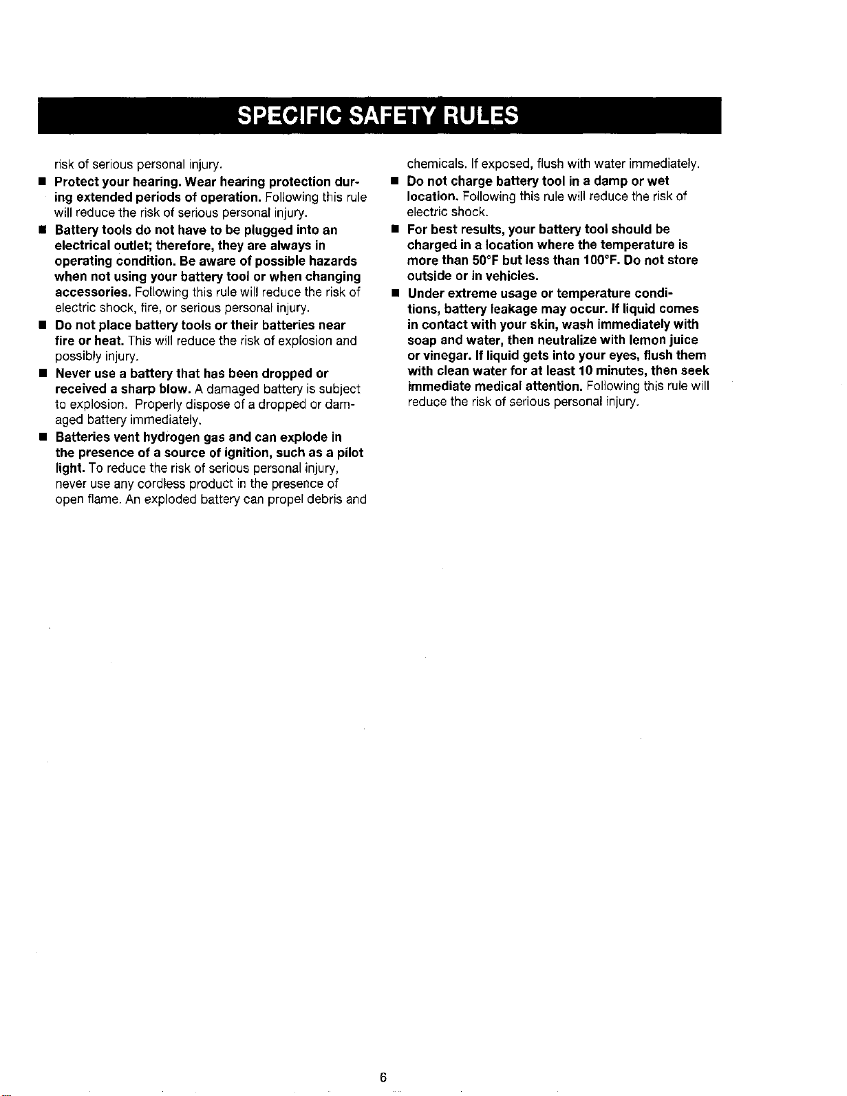
• Protect your hearing. Wear hearing protection dur-
ing extended periods of operation. Following this rule
will reduce the riskof serious personal injury.
• Battery tools do not have to be plugged into an
electrical outlet; therefore, they are always in
operating condition. Be aware of possible hazards
when not using your battery tool or when changing
accessories, Following this rule will reduce the risk of
electric shock, fire, or serious personal injury.
• Do not place battery tools or their batteries near
fire or heat. This will reduce the risk of explosion and
possibly injury.
• Never use a battery that has been dropped or
received a sharp blow. A damaged battery is subject
to explosion. Properly dispose of adropped or dam-
aged battery immediately.
• Batteries vent hydrogen gas and can explode in
the presence of a source of ignition, such as a pilot
light. To reduce the risk of serious personal injury,
never use any cordless product in the presence of
open flame. An exploded battery can propel debris and
chemicals. If exposed, flush with water immediately.
• Do not charge battery tool in a damp or wet
location. Following this rule will reduce the risk of
electric shock.
• For best results, your battery tool should be
charged in a location where the temperature is
more than 50°F but less than 100°F. Do not store
outside or in vehicles.
• Under extreme usage or temperature condi-
tions, battery leakage may occur, if liquid comes
in contact with your skin, wash immediately with
soap and water, then neutralize with lemon juice
or vinegar. If liquid gets intoyour eyes, flushthem
with clean water for at least 10 minutes, then seek
immediate medical attention. Following this rule will
reduce the risk of serious personal injury.
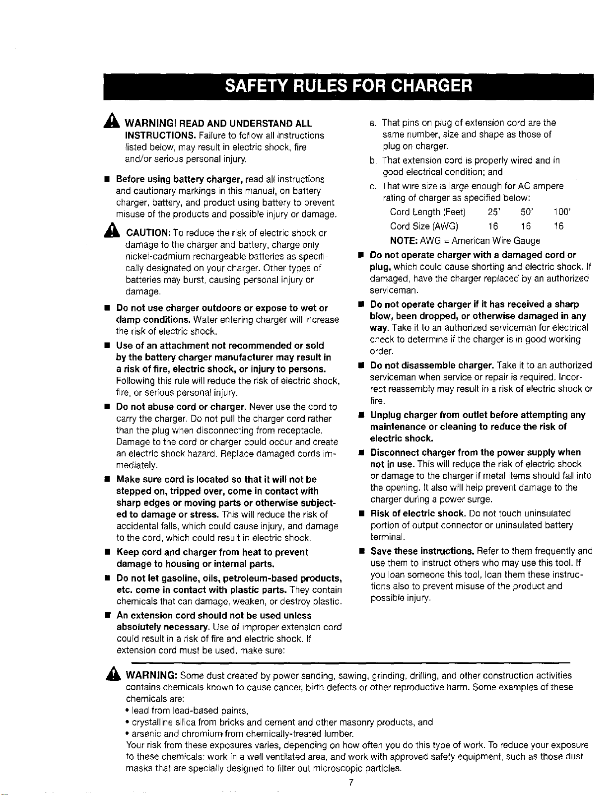
_ WARNING) READAND UNDERSTAND ALL
INSTRUCTIONS. Failure to follow all instructions
listed below, may result in electric shock, fire
and/or serious personal injury.
• Before using battery charger, read all instructions
and cautionary markings in this manual, on battery
charger, battery, and product using battery to prevent
misuse of the products and possible injury or damage.
_1, CAUTION: To reduce the risk of electric shock or
damage to the charger and battery, charge only
nickel-cadmium rechargeable batteries as specifi-
cally designated on your charger. Other types of
batteries may burst, causing personal injury or
damage.
• Do not use charger outdoors or expose to wet or
damp conditions. Water entering charger will increase
the risk of electric shock.
• Use of an attachment not recommended or sold
by the battery charger manufacturer may result in
a risk of fire, electric shock, or injury to persons.
Following this rule will reduce the risk of electric shock,
fire, or serious personal injury.
• Do not abuse cord or charger. Never use the cord to
carry the charger. Do not pull the charger cord rather
than the plug when disconnecting from receptacle.
Damage to the cord or charger could occur and create
an electric shock hazard. Replace damaged cords im-
mediately.
• Make sure cord is located so that itwill not be
stepped on, tripped over, come in contact with
sharp edges or moving parts or otherwise subject-
ed to damage or stress. Thiswill reduce the riskof
accidental falls, which could cause injury, and damage
to the cord, which could result in electric shock.
• Keep cord and charger from heat to prevent
damage to housing or internal parts.
• Do not let gasoline, oils, petroleum-based products,
etc. come in contact with plastic parts. They contain
chemicals that can damage, weaken, or destroy plastic.
• An extension cord should not be used unless
absolutely necessary. Use of improper extension cord
could result in a risk of fire and electric shock. If
extension cord must be used, make sure:
a. That pins on plug of extension cord are the
same number, size and shape as those of
plug on charger.
b. That extension cord is properly wired and in
good electrical condition; and
c. That wire size is large enough for AC ampere
rating of charger as specified below:
Cord Length (Feet) 25' 50' 100'
Cord Size (AWG) 16 16 16
NOTE: AWG = American Wire Gauge
• Do not operate charger with a damaged cord or
plug, which could cause shorting and electric shock. If
damaged, have the charger replaced by anauthorized
serviceman.
• Do not operate charger if it has received a sharp
blow, been dropped, or otherwise damaged in any
way. Take itto an authorized serviceman for electrical
check to determine if the charger is in good working
order.
• Do not disassemble charger. Take it to an authorized
serviceman when service or repair isrequired. Incor-
rect reassembiy may result in a risk of electric shock or
fire.
• Unplug charger from outlet before attempting any
maintenance or cleaning to reduce the risk of
electric shock.
• Disconnect charger from the power supply when
not in use. This will reduce the risk of electric shock
or damage to the charger if metal items should fall into
the opening. (t also will heip prevent damage to the
charger during a power surge.
• Risk of electric shock. Do not touch uninsulated
portion of output connector or uninsulated battery
terminal.
• Save these instructions. Refer to them frequently and
use them to instruct others who may use this tool. If
you loan someone this tool, loan them these instruc-
tions also to prevent misuse of the productand
possible injury.
_1, WARNING: Some dust created by power sanding, sawing, grinding, dri(ling, and other construction activities
contains chemicals known to cause cancer, birth defects or other reproductive harm. Some examples of these
chemicals are:
• lead from lead-based paints,
• crystalline silica from bricks and cement and other masonry products, and
• arsenic and chromiu_from chemically-treated lumber.
Your risk from these exposures varies, depending on how often you dothis type of work. To reduce your exposure
to these chemicals: work in a well ventilated area, and work with approved safety equipment, such as those dust
masks that are specially designed to filter out microscopic particles.
7

Someofthefollowingsymbolsmaybeusedonthistool.Pleasestudythemandlearntheirmeaning.Properinterpreta-
tionofthesesymbolswillallowyoutooperatethetoolbetterandsafer.
SYMBOL NAME DESIGNATION/EXPLANATION
V Volts
A Amperes
Hz Hertz
W Watt
min Minutes
Alternating Current
--= Direct Current
no No Load Speed
[] Class II Construction
.../rain Per Minute
Wet Conditions Alert
Read The Operator's Manual
EyeProtection
Safety Alert
No Hands Symbol
No Hands Symbol
No Hands Symbol
No Hands Symbol
Hot Surface
@
O
A
®
®
@
®
Voltage
Current
Frequency (cycles per second)
Power
Time
Type of current
Type or a characteristic of current
Rotational speed, at no load
Double-insulated construction
Revolutions, strokes, surface speed, orbits etc., per minute
Do not expose to rain or use in damp locations.
To reduce the risk of injury, user must read and understand
operator's manual before using this product.
Always wear safety goggles or safety glasses with side shields,
or a full face shield when operating this product.
Precautions that involve your safety.
Failureto keepyour hands away from the blade will result in
serious personal injury.
Failureto keepyour hands away from the blade will result in
serious personal injury.
Failureto keepyour hands away from the blade will result in
serious personal injury.
Failureto keepyour hands away from the blade will result in
serious personal injury.
To reduce the risk of injury or damage, avoid contact with
any hot surface.
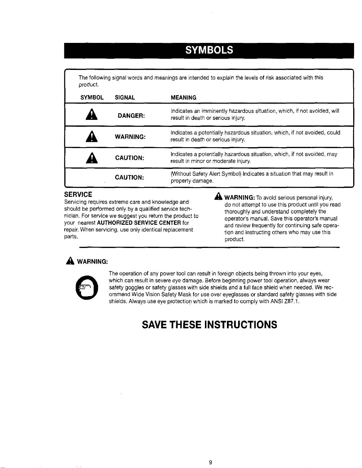
Thefollowingsignalwordsandmeaningsareintendedtoexplainthelevelsofriskassociatedwiththis
product.
SYMBOL SIGNAL MEANING
,_ DANGER:
Indicates an imminently hazardous situation, which, if not avoided, will
result in death or serious injury.
A WARNING:
Indicates a potentially hazardous situation, which, if not avoided, could
result in death or serious injury.
_IL CAUTION:
Indicates a potentially hazardous situation, which, if not avoided, may
result in minor or moderate injury.
CAUTION:
(Without Safety Alert Symbol) Indicates a situation that may result in
property damage.
SERVICE
Servicing requires extreme care and knowledge and
should be performed only by a qualified service tech-
nician. For service we suggest you return the product to
your nearestAUTHORIZED SERVICE CENTER for
repair.When servicing, use only identical replacement
parts.
WARNING: Toavoid serious personal injury,
do not attempt to use this product until you read
thoroughly and understand completely the
operator's manual. Save this operator's manual
and review frequently for continuing safe opera-
tion and instructing others who may use this
product.
,_ WARNING:
O
The operation of any power tool can result inforeign objects being thrown into your eyes,
which can result in severe eye damage. Before beginning power tool operation, always wear
safety goggles orsafety glasses with side shields and a full face shield when needed. Werec-
ommend Wide Vision Safety Mask for useover eyeglasses or standard safety glasses with side
shields. Always use eye protection which is marked to comply with ANSI Z87.1.
SAVE THESEINSTRUCTIONS
9
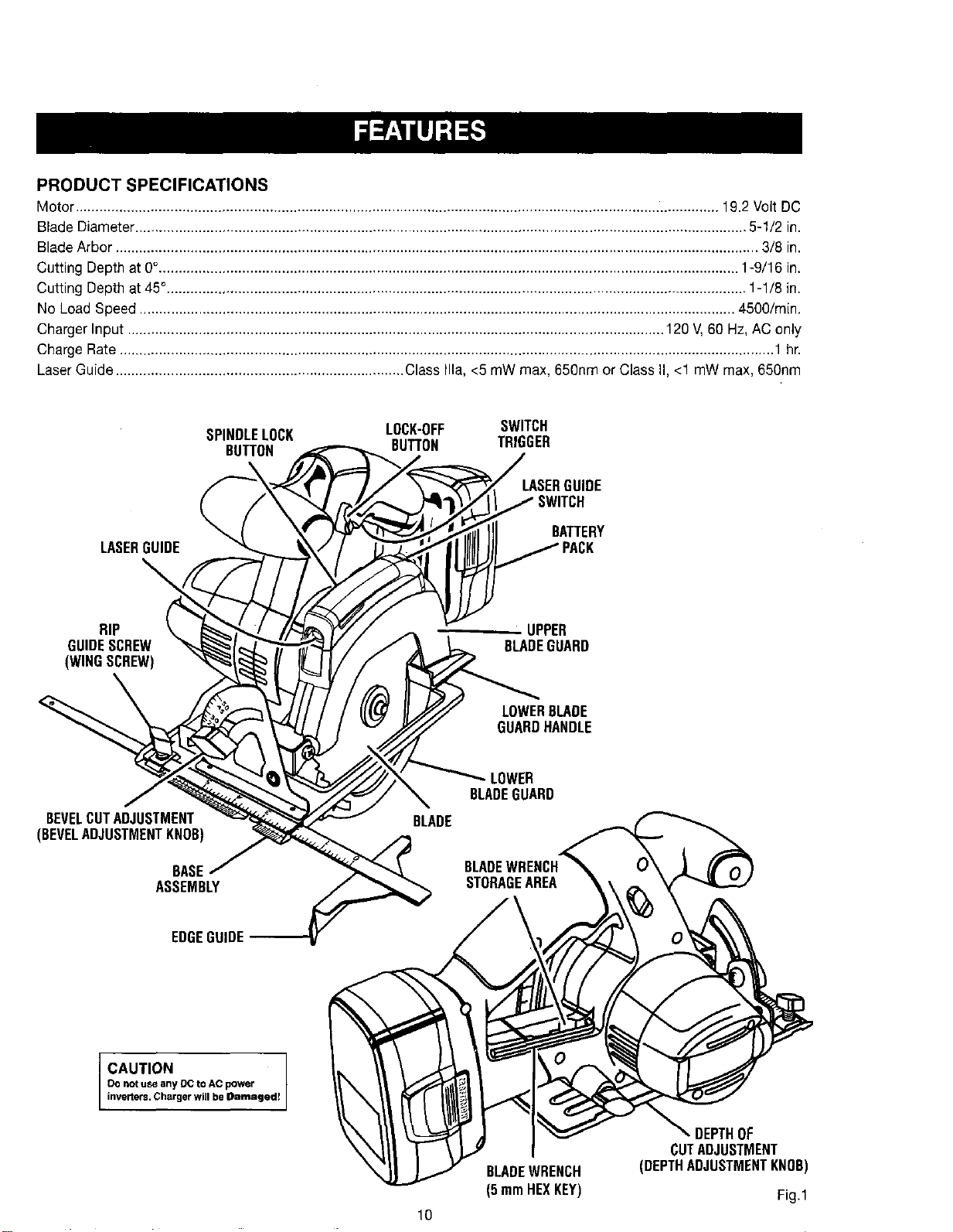
PRODUCT SPECIFICATIONS
Motor................................................................................................................................................................... 19.2 Volt DC
Blade Diameter........................................................................................................................................................... 5-1/2 in.
Blade Arbor................................................................................................................................................................... 3/8 in.
Cutting Depthat 0%.................................................................................................................................................. 1-9/16 in.
Cutting Depthat 45°................................................................................................................................................... 1-1/8 in.
No LoadSpeed ....................................................................................................................................................... 4500/min.
Charger Input ........................................................................................................................................ 120 V,60 Hz, AC only
Charge Rate...................................................................................................................................................................... 1 hr.
LaserGuide......................................................................... ClassIlia, <5 mW max, 650nm or Class II,<1 mW max, 650nm
SPINDLELOCK LOCK-OFF SWITCH
BUTTON BUTTON TRIGGER
LASERGUIDE
LASERGUIDE
BATTERY
RIP _ UPPER
GUIDESCREW BLADEGUARD
(WINGSCREW)
LOWERBLADE
GUARDHANDLE
BEVELCUTADJUSTMENT
(BEVELADJUSTMENTKNOB)
BASE
ASSEMBLY
LOWER
BLADEGUARD
EDGEGUIDE
CAUTION
Do not use any De to AC power
inveners. Charger will be Damaged!
10
BLADEWRENCH
(5 mmHEXKEY)
DEPTHOF
CUTADJUSTMENT
(DEPTHADJUSTMENTKNOB)
Fig.1
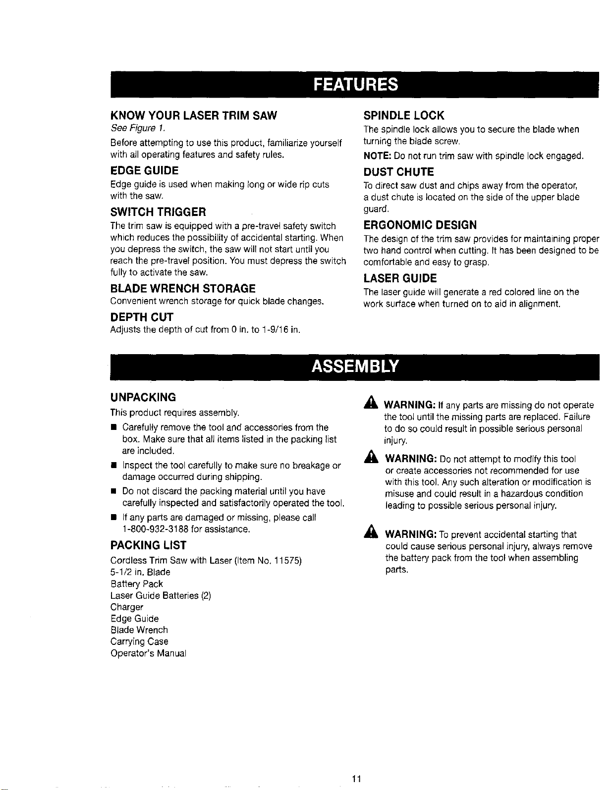
KNOW YOUR LASER TRIM SAW
See Figure 1.
Before attempting to use this product, familiarize yourself
with all operating features and safety rules.
EDGE GUIDE
Edge guide is used when making long or wide rip cuts
with the saw.
SWITCH TRIGGER
Thetrim saw is equipped with a pre-travel safety switch
which reduces the possibility of accidental starting. When
you depress the switch, the sawwill not start until you
reach the pre-travel position. You must depress the switch
fully to activate the saw.
BLADE WRENCH STORAGE
Convenient wrench storage for quick blade changes.
DEPTH CUT
Adjusts the depth of cut from 0 in. to 1-9/16 in.
SPINDLE LOCK
The spindle lock allows you to secure the blade when
turning the blade screw.
NOTE: Do not run trim saw with spindle lock engaged.
DUST CHUTE
To direct saw dust and chips away from the operator,
a dust chute is located on the side of the upper blade
guard.
ERGONOMIC DESIGN
The design of the trim saw provides for maintaining proper
two hand control when cutting. It has been designed to be
comfortable and easy to grasp.
LASER GUIDE
The laserguide will generate ared colored line on the
work surface when turned on to aid in alignment.
UNPACKING
Thisproduct requires assembly.
• Carefully remove the tool and accessories from the
box. Make sure that all items listed in the packing list
are included. ,_
• Inspect the tool carefully to make sure no breakage or
damage occurred during shipping.
• Do not discard the packing material until you have
carefully inspected and satisfactorily operated the tool.
• If any parts are damaged or missing, please call
1-800-932-3188 for assistance,
PACKING LIST
Cordless TrimSaw with Laser(Item No. 11575)
5-1/2 in.Blade
Battery Pack
Laser Guide Batteries (2)
Charger
Edge Guide
Blade Wrench
Carrying Case
Operator's Manual
WARNING: If any parts are missing do not operate
the tool until the missing parts are replaced. Failure
to do so couldresult in possible serious personal
injury.
WARNING: Do not attempt to modify this tool
or create accessories not recommended for use
with this tool. Any such alteration or modification is
misuse and could result in a hazardous condition
leading to possible serious personal injury.
WARNING: Toprevent accidental starting that
could cause serious personal injury, always remove
the battery pack from the tool when assembling
parts.
11
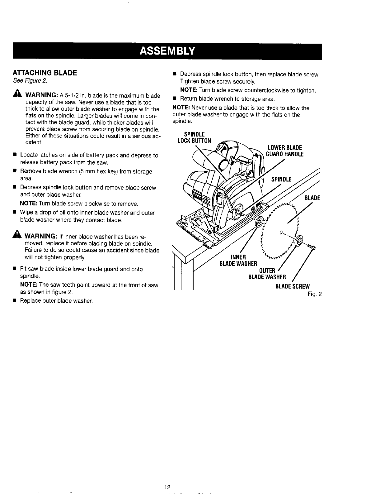
ATTACHING BLADE
SeeFigure2.
P,
WARNING: A 5-1/2 in. blade is the maximum blade
capacity of the saw. Never use a blade that is too
thick to allow outer blade washer to engage with the
flats on the spindle. Larger blades will come in con-
tact with the blade guard, while thicker blades will
prevent blade screw from securing blade on spindle.
Either of these situations could result in a serious ac-
cident.
• Locate latches on side of battery pack and depress to
releasebattery pack from the saw.
• Remove blade wrench (5 mm hex key)from storage
area.
• Depress spindle lock button and remove blade screw
and outer blade washer.
NOTE: Turn blade screw clockwise to remove.
• Wipe a drop of oil onto inner blade washer and outer
blade washer where they contact blade.
,&
AI& WARNING: If inner blade washer has been re-
moved, replace it before placing blade on spindle.
Failureto do so could cause an accident since blade
will not tighten properly.
• Fit saw blade inside lower blade guard and onto
spindle.
NOTE: The saw teeth point upward at the front of saw
as shown in figure 2.
• Replace outer blade washer.
• Depress spindle lock button, then replace blade screw.
Tighten blade screw securely.
NOTE: Turnblade screw counterclockwise to tighten.
• Return blade wrench to storage area.
NOTE: Never use a blade that istoo thick to allow the
outer blade washer to engage with the flats on the
spindle.
SPINDLE
LOCKBUTTON
LOWERBLADE
GUARDHANDLE
BLADE
J
INNER
BLADEWASHER
BLADEWASHER
BLADESCREW
Fig.2
12
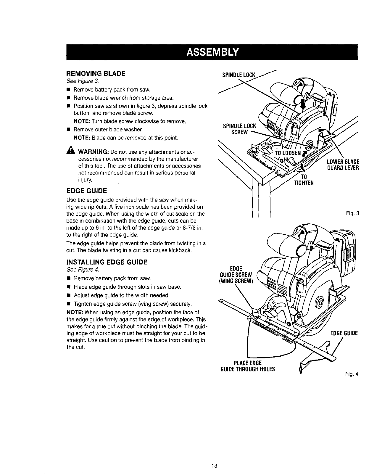
REMOVING BLADE
See Figure3.
• Remove battery pack from saw.
• Remove blade wrench from storage area.
• Position saw as shown in figure 3, depress spindle lock
button, and remove blade screw.
NOTE: Turn blade screw clockwise to remove.
• Remove outer blade washer.
NOTE; Blade can be removed at this point.
_ WARNING: Do not use any attachments or ac-
cessories not recommended by the manufacturer
of this tool. The use of attachments or accessories
not recommended can result in serious personal
injury.
EDGE GUIDE
Use the edge guide provided with the saw when mak-
ing wide rip cuts. A five inch scale has been provided on
the edge guide. When using the width of cut scale on the
base in combination with the edge guide, cuts can be
made up to 6 in. to the left of the edge guide or 8-7/8 in.
to the right of the edge guide.
The edge guide helps prevent the blade from twisting in a
cut. The blade twisting in a cut can cause kickback.
INSTALLING EDGE GUIDE
See Figure4.
• Remove battery pack from saw.
• Place edge guide through slots in saw base.
• Adjust edge guide to the width needed.
• Tighten edge guide screw (wing screw) securely.
NOTE: When using an edge guide, position the face of
the edge guide firmly against the edge of workpiece. This
makes for a true cut without pinching the blade. The guid-
ing edge of workpiece must be straight for your cut to be
straight. Use caution to prevent the blade from binding in
the cut.
SPINDLELOCK
SCREW
\
\
EDGE
GUIDESCREW
(WINGSCREW)
TO
TIGHTEN
LOWER6LADE
GUARDLEVER
Fig.3
EDGEGUIDE
PLACEEDGE
GUIDETHROUGHHOLES
Fig, 4
13

_, WARNING: Do not allow familiarity with tools to
make you careless. Remember that a careless
fraction of a second issufficient to inflict serious
injury,
_, WARNING: Always wear safety goggles or safety
glasses with side shields when operating tools,
Failureto do so could result in objects being thrown
into your eyes, resulting in possible serious injury.
APPLICATIONS
You may use this tool for the following purposes:
• Cutting all types of wood products (lumber, plywood,
paneling)
• Cross Cutting/Rip Cutting
• Bevel Cutting
• Pocket Cutting
CAUTION: If at any point during the charging pro-
cess none of the LEDs are lit, remove the battery pack
from the charger to avoid damaging the product. DO
NOT insert another battery. Return the charger and
battery to your nearest service center for service or
replacement.
LED FUNCTIONS OF CHARGER
LED WILL BE ON TO INDICATE STATUS OF
CHARGER AND BATTERY PACK:
• Red LEDon = Fast charging mode.
• Green LED on = Fully charged and in maintenance
charge mode.
• Green LEDon =When battery pack is inserted into
charger, indicates hot battery pack or that battery pack
is out of normal temperature range.
• Yellow and Green LEDs on = Deeply discharged or
defective battery pack.
• No LEDon = Defective charger or battery pack.
CHARGING THE BATTERY PACK
The battery pack for this tool has been shipped in a low
charge condition to prevent possible problems. Therefore,
you should charge it until the green LEDon the front of the
charger comes on.
NOTE: Batteries will not reach full charge the first time
they are charged, Allow several cycles (operation followed
by recharging) for them to become fully charged.
CAUTION I
0o not use any DC to AC power
]nverters. Charger will be Damaged!
CHARGING A COOL BATTERY PACK
If battery pack is below normal temperature range, the
green LED on charger will come on. Allow battery pack to
reach normal temperature, then the red LEDwill come on.
NOTE: If the charger does not charge the battery pack
under normal circumstances, return both the battery pack
and charger to your nearest Sears Repair Centerfor
electrical check.
• Charge the battery pack only with the charger provided.
• Make surethe power supply is normal household
voltage, 120 volts, 60 Hz, AC only.
• Connect the charger to the power supply.
• Place the battery pack in the charger aligning raised rib
on the battery pack with the groove in the charger. See
Figure 6.
• Press down on the battery pack to be sure contacts on
the battery pack engage properly with contacts in the
charger,
• Normally the red LED on charger will come on. This
indicates the charger is in fast charging mode.
• Red LED should remain on for approximately 1 hour
then the green LEDwill come on. Green LEDon
indicates battery pack is fully charged and charger is
in maintenance charge mode.
NOTE: The green LEDwill remain on until the battery
pack is removed from the charger or charger is
disconnected from the power supply.
• If both yellow and green LEDs come on, this indicates
a deeply discharged or defective battery pack. Allow
the battery pack to remain in the charger for 15 to 30
minutes. When the battery pack reaches normal
voltage range, the red LED should come on. If the red
LEDdoes not come on after 30 minutes, this may
indicate a defective battery pack and should be
replaced.
• After normal usage, a minimum of 1 hour of charging
time is required to fully recharge battery pack.
• The battery pack will become slightly warm to the
touch while charging. This is normal and does not
indicate a problem.
• Do not place the charger and battery pack in an area
of extreme heat or cold. They will work best at normal
room temperature,
NOTE: The charger and battery pack should be placed
in a location where the temperature is more than 50°F
but less than 100°F.
• When batteries become fully charged, unplug the
charger from power supply and remove the battery
pack.
14
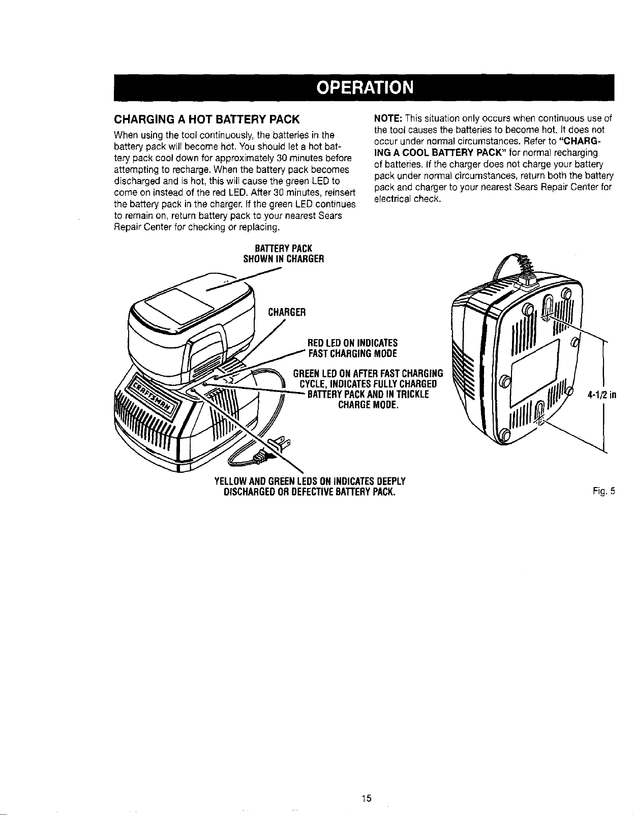
CHARGING A HOT BATTERY PACK
When using the tool continuously, the batteries in the
battery pack will become hot. You should let a hot bat-
tery pack cool down for approximately 30 minutes before
attempting to recharge.When the battery pack becomes
discharged and is hot, this will cause the green LED to
come on instead of the red LED.After 30 minutes, reinsert
the battery pack in the charger, If the green LEDcontinues
to remain on, return battery pack to your nearest Sears
Repair Center for checking or replacing.
BArrERYPACK
SHOWNINCHARGER
CHARGER
NOTE: This situation only occurs when continuous use of
the tool causes the batteries to become hot. It does not
occur under normal circumstances. Refer to "CHARG-
ING A COOL BATTERYPACK" for normal recharging
of batteries. If the charger does not charge your battery
pack under normal circumstances, return both the battery
pack and charger to your nearest Sears Repair Center for
electrical check.
REDLEDONINDICATES
GREENLEDONAFTERFASTCHARGING
CYCLE,INDICATESFULLYCHARGED
BATTERYPACKANDINTRICKLE
CHARGEMODE,
4-1/2in
YELLOWANDGREENLEDSONINDICATESDEEPLY
DISCHARGEDORDEFECTIVEBATTERYPACK. Fig. 5
15
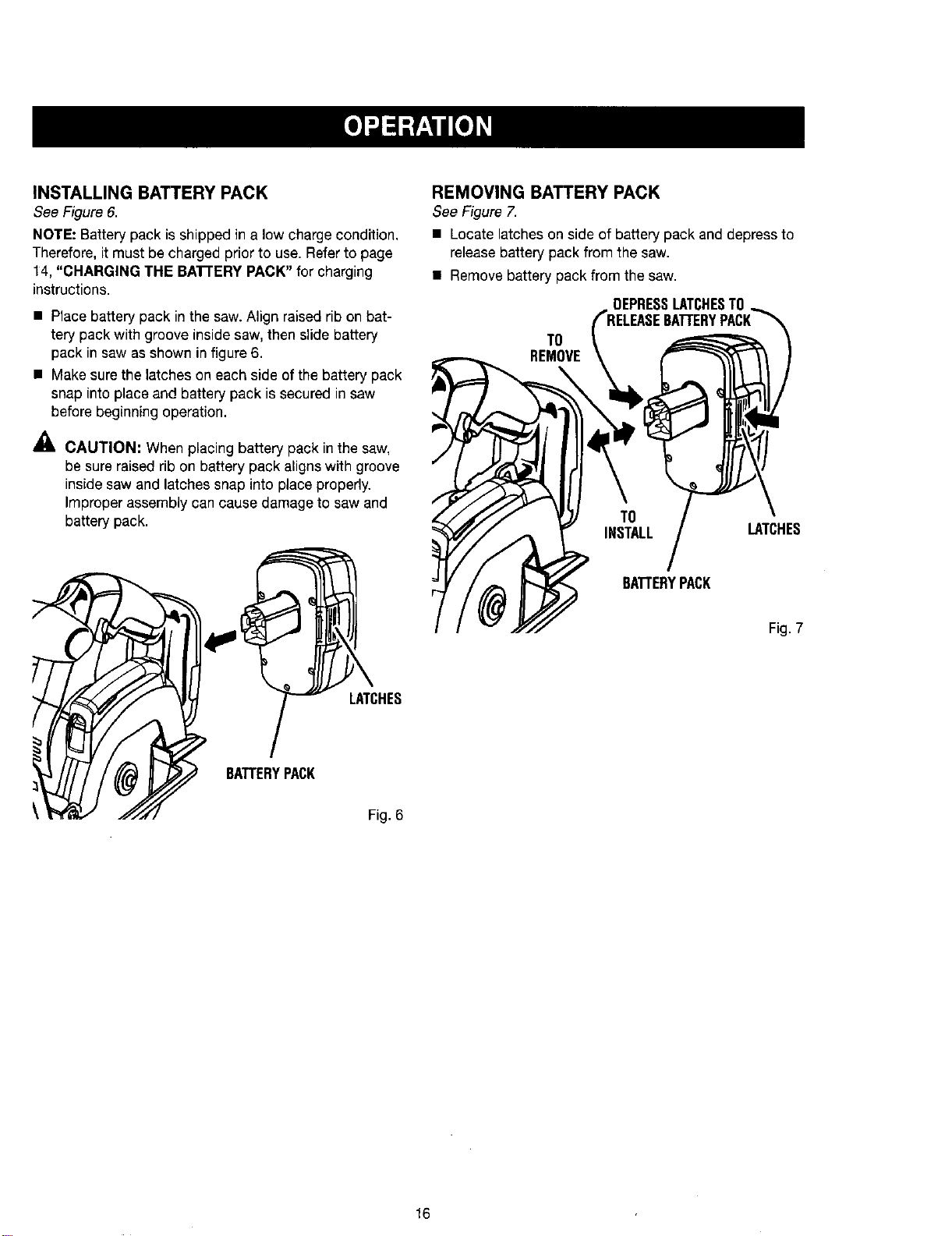
INSTALLING BATTERY PACK
See Figure6.
NOTE: Batterypack isshippedin a low chargecondition,
Therefore,itmustbe chargedpriorto use. Referto page
14, "CHARGING THE BA'rrERY PACK" for charging
instructions.
• Place battery pack inthe saw. Align raised rib on bat-
tery pack with groove inside saw, then slide battery
pack in saw as shown in figure 6.
• Make sure the latches on each side of the battery pack
snap into place and battery pack is secured in saw
before beginning operation.
CAUTION; When placing battery pack in the saw,
be sure raised rib on battery pack aligns with groove
inside saw and latches snap into place properly.
Improper assembly can cause damage to saw and
battery pack.
REMOVING BATTERY PACK
See Figure7.
• Locatelatchesonside of battery pack and depressto
releasebattery packfrom the saw.
• Remove battery pack from the saw.
DEPRESSLATCHESTO
TO
REMOVE
TO
INSTALL LATCHES
BATTERYPACK
Fig. 7
LATCHES
BATTERYPACK
Fig. 6
16
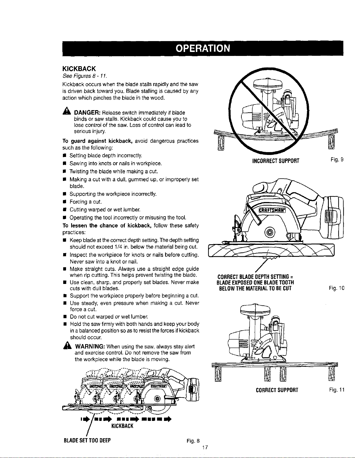
KICKBACK
See Figures 8- 11.
Kickback occurs when the blade stalls rapidly and the saw
is driven back toward you. Blade stalling is caused by any
action which pinches the blade in the wood.
,_, DANGER: Release switch immediately if blade
binds or saw stalls. Kickback could cause you to
lose control of the saw. Loss of control can lead to
serious injury.
To guard against kickback, avoid dangerous practices
such as the following:
• Setting blade depth incorrectly.
n Sawing into knots or nails in workpiece.
• Twisting the blade while making a cut.
• Making a cut with a dull, gummed up, or improperly set
blade.
• Supporting the workpiece incorrectly.
• Forcing a cut.
• Cutting warped or wet lumber.
• Operating the tool incorrectly or misusing the tool.
To lessen the chance of kickback, follow these safety
practices:
• Keepbladeatthecorrectdepthsetting. Thedepthsetting
should not exceed 1/4 in. below the material being cut.
• Inspect the workpiece for knots or nails before cutting.
Never saw into a knot or nail.
• Make straight cuts. Always use a straight edge guide
when rip cutting. This helps prevent twisting the blade.
• Use clean, sharp, and properly set blades. Never make
cuts with dull blades.
• Support the workpiece properly before beginning a cut.
• Use steady, even pressure when making a cut. Never
force a cut.
• Do not cut warped or wet lumber.
• Hold the saw firmly with both hands and keepyour body
in a balanced position so asto resisttheforces if kickback
should occur.
WARNING: When using the saw, always stay alert
and exercise control. Do not remove the saw from
the workpiece while the blade is moving.
INCORRECTSUPPORT
CORRECTBLADEDEPTHSETTING=
BLADEEXPOSEDONEBLADETOOTH
BELOWTHEMATERIALTOBECUT
Fig. 9
Fig, 10
'0 "•- ml .m•• mmim .
KICKBACK
BLADESETTOODEEP Fig. 8
17
CORRECTSUPPORT
Fig. 11
SAW BLADES
The best of saw blades will not cut efficiently if they are
not kept clean, sharp, and properly set. Using a dull blade
will place a heavy load on the saw and increase the dan-
ger of kickback. Keep extra blades on hand, so that sharp
blades are always available.
Gum and wood pitch hardened on blades will slow the
saw down. Remove saw blade from the saw and use gum
and pitch remover, hot water, or kerosene to remove these
accumulations. OO NOT USE GASOLINE.
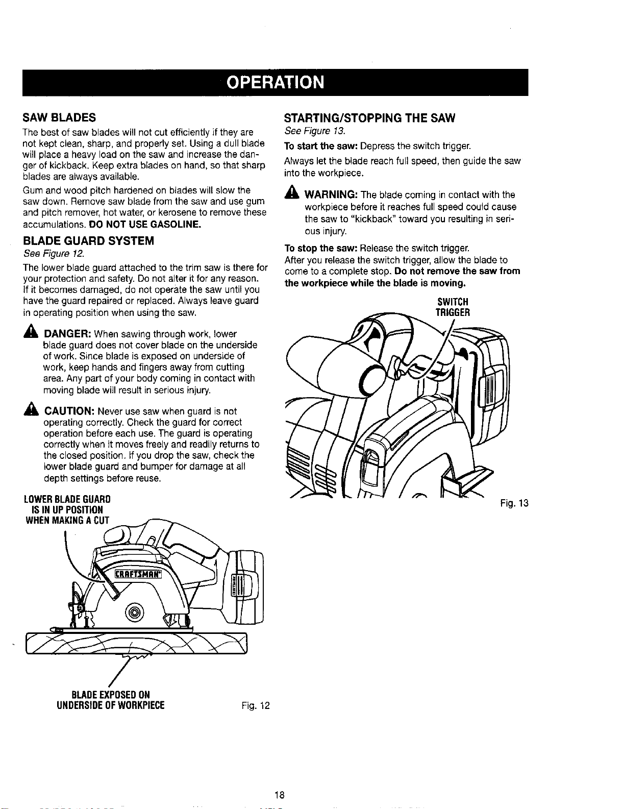
BLADE GUARD SYSTEM
See Figure 12.
The lower blade guard attached to the trim saw is there for
your protection and safety. Do not alter it for any reason.
If it becomes damaged, do not operate the saw until you
havethe guard repaired or replaced. Always leave guard
in operating position when using the saw.
_lL DANGER: When sawing through work, lower
blade guard does not cover blade on the underside
of work. Since blade is exposed on underside of
work, keep hands and fingers away from cutting
area. Any part of your body coming in contact with
moving blade will result in serious injury.
_, CAUTION: Never use saw when guard is not
operating correctly. Check the guard for correct
operation before each use. The guard is operating
correctly when it moves freely and readily returns to
the closed position. If you drop the saw, check the
lower blade guard and bumper for damage at all
depth settings before reuse.
LOWERBLADEGUARD
ISINUPPOSITION
WHENMAKINGACUT
STARTING/STOPPING THE SAW
See Figure 13,
To start the saw: Depress the switch trigger.
Always let the blade reach full speed, then guide the saw
into the workpiece.
_1_ WARNING: The blade coming in contact with the
workpiece before it reaches full speed could cause
the saw to "kickback" toward you resulting in seri-
ous injury.
Tostop the saw: Releasethe switch trigger.
After you release the switch trigger, allow the blade to
come to a complete stop, Do not remove the saw from
the workpiece while the blade is moving.
SWITCH
TRIGGER
Fig. 13
BLADEEXPOSEDON
UNDERSIDEOFWORKPIECE
Fig. 12
18
_, WARNING; Always remove battery pack from the
tool when changing operation settings or when the
tool is not in use. Failureto remove the battery pack
may result in accidental starting and serious per-
sonal injury.
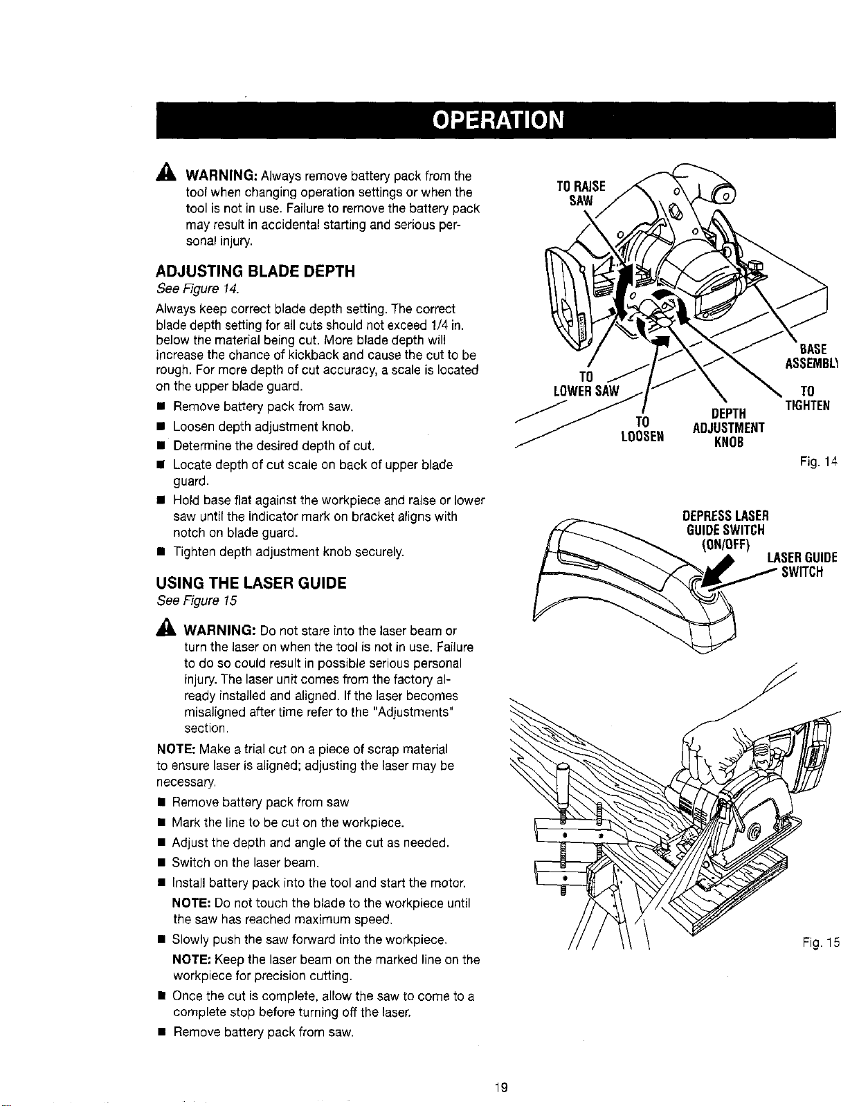
ADJUSTING BLADE DEPTH
See Figure 14.
Always keep correct blade depth setting. The correct
blade depth setting for all cuts should net exceed 1/4 in.
below the material being cut. More blade depth will
increase the chance of kickback and cause the cut to be
rough. For more depth of cut accuracy, a scale is located
on the upper blade guard.
• Remove battery pack from saw.
• Loosen depth adjustment knob.
• Determine the desired depth of cut.
• Locate depth of cut scale on back of upper blade
guard.
• Hold base flat against the workpiece and raise or lower
saw until the indicator mark on bracket aligns with
notch on blade guard.
• Tighten depth adjustment knob securely.
USING THE LASER GUIDE
See Figure 15
WARNING: Do not stare into the laser beam or
turn the laser on when the tool is not in use. Failure
to do so could result in possible serious personal
injury. The laser unit comes from the factory al-
ready installed and aligned. Ifthe laser becomes
misaligned after time referto the "Adjustments"
section.
NOTE: Make a trial cut on a piece of scrap material
to ensure laser is aligned; adjusting the Fasermay be
necessary.
• Remove battery pack from saw
• Mark the line to be cut on the workpiece.
• Adjust the depth and angle of the cut as needed.
• Switch on the laser beam.
• Install battery pack into the tool and start the motor.
NOTE: Do not touch the blade to the workpiece until
the saw has reached maximum speed.
• Slowly push the saw forward into the workpiece.
NOTE" Keep the laser beam on the marked line on the
workpiece for precision cutting.
• Once the cut is complete, allow the saw to come to a
complete stop before turning off the laser.
• Remove battery pack from saw.
TORAISE
SAW
TO
LOWERSAW
TO
LOOSEH
BASE
ASSEMB_
TO
TIGHTEN
DEPTH
ADJUSTMENT
KNOB
Fig. 14
DEPRESSLASER
GUIDESWITCH
(ON/OFF)
LASERGUIDE
SWITCH
Fig. 15
19
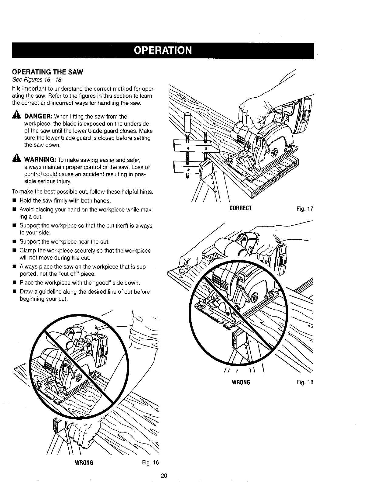
OPERATING THE SAW
See Figures 16 - 18.
It is important to understand the correct method for oper-
ating the saw. Refer to the figures in this section to learn
the correct and incorrect ways for handling the saw.
DANGER: When lifting the saw from the
workpiece, the blade is exposed on the underside
of the saw until the lower blade guard closes. Make
sure the lower blade guard is closed before setting
the saw down.
_. WARNING: Tomake sawing easier and safer,
always maintain proper control of the saw. Loss of
control could cause an accident resulting in pos-
sible serious injury.
To make the best possible cut, follow these helpful hints.
• Hold the saw firmly with both hands.
• Avoid placing your hand on the workpiece while mak-
ing a cut.
• Suppo[t the workpiece so that the cut (kerr)is always
to your side.
• Support the workpiece near the cut.
• Clamp the workpiece securely so that the workpiece
will not move during the cut.
• Always place the saw on the werkpiece that is sup-
ported, not the "cut off" piece.
• Placethe workpiece with the "good" side down.
• Draw a guideline along the desired line of cut before
beginning your cut.
CORRECT
// / \\
WRONG
Fig. 17
Fig. 18
WRONG
Fig. 16
2O
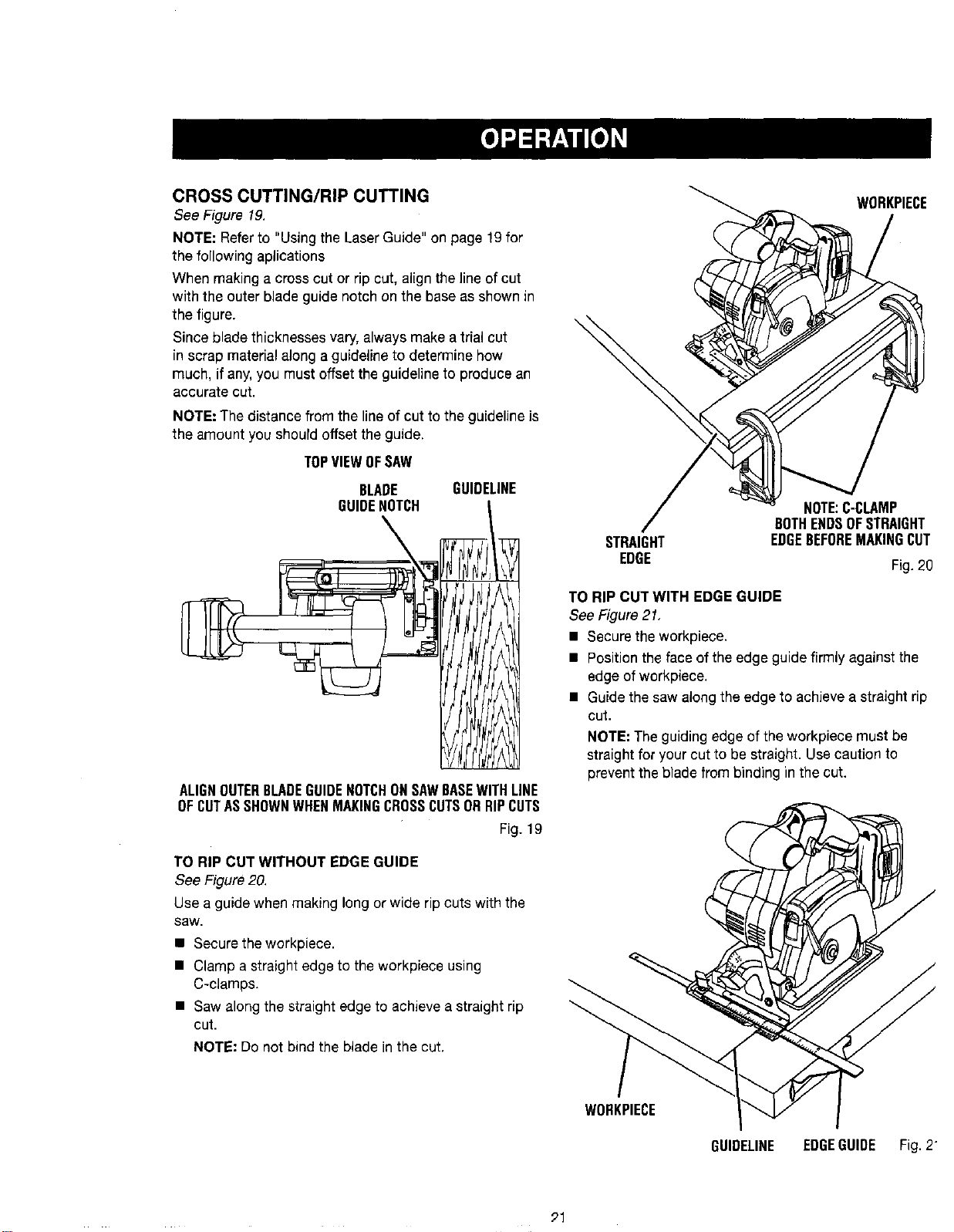
CROSS CUTTING/RIP CUTTING
See Figure 19.
NOTE: Refer to "Using the Laser Guide" on page 19for
the following aplications
When making a cross cut or rip cut, align the line of cut
with the outer blade guide notch on the base as shown in
the figure.
Since blade thicknesses vary, always make a trial cut
in scrap material along a guideline to determine how
much, if any, you must offset the guideline to produce an
accurate cut.
NOTE: The distance from the line of cut to the guideline is
the amount you should offset the guide.
TOPVIEWOFSAW
BLADE GUIDELINE
GUIDENOTCH [
\
ALIGNOUTERBLADEGUIDENOTCHONSAWBASEWITHLINE
OFCUTASSHOWNWHENMAKINGCROSSCUTSORRIPCUTS
Fig. 19
TO RIP CUT WITHOUT EDGE GUIDE
See Figure 20.
Use a guide when making long or wide rip cuts with the
saw.
• Secure the werkpiece.
• Clamp a straight edge to the workpiece using
C-clamps.
• Saw along the straight edge to achieve a straight rip
cut.
NOTE: Do not bind the blade in the cut.
WURKPIECE
STRAIGHT
EDGE
NOTE:C-CLAMP
BOTHENDSOFSTRAIGHT
EDGEBEFOREMAKINGCUT
Fig. 20
TO RIP CUT WITH EDGE GUIDE
See Figure21,
• Secure the workpiece.
• Positiontheface ofthe edge guidefirmly against the
edge ofworkpiece,
• Guide the saw alongthe edge to achievea straight rip
cut.
NOTE: The guiding edge of the workpiece must be
straight for your cut to be straight. Use caution to
prevent the blade from binding in the cut.
WOHKPIECE
GUIDELINE EDGEGUIDE Fig. 2
91
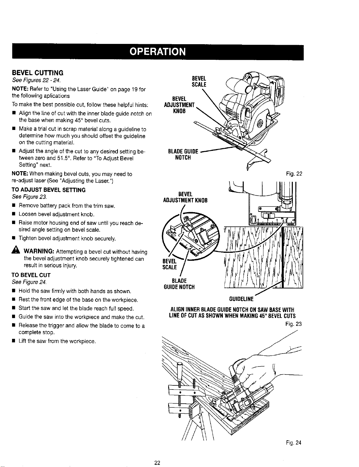
BEVEL CUTTING
See Figures 22 - 24.
NOTE; Referto "Using the Laser Guide" on page 19 for
the following aplications
Tomake the best possible cut, follow these helpful hints:
• Align the line of cut with the inner blade guide notch on
the base when making 45° bevel cuts.
• Make a trial cut in scrap material along a guideline to
determine how much you should offset the guideline
on the cutting material.
• Adjust the angle of the cut to any desired setting be-
tween zero and 51.5°. Refer to "To Adjust Bevel
Setting" next.
NOTE: When making bevel cuts, you may need to
re-adjust laser(See "Adjusting the Laser.")
TO ADJUST BEVEL SETTING
See Figure23.
• Remove battery pack from the trim saw.
• Loosen bevel adjustment knob.
• Raise motor housing end of saw until you reach de-
sired angle setting on bevel scale.
• Tighten bevel adjustment knob securely.
WARNING: Attempting a bevel cut without having
the bevel adjustment knob securely tightened can
result in serious injury.
TO BEVEL CUT
See Figure 24.
• Hold the saw firmly with both hands as shown.
• Restthe front edge of the base on the workpiece.
• Start the saw and let the blade reach full speed.
• Guide the saw into the workpiece and make the cut.
• Releasethe trigger and allow the blade to come to a
complete stop.
• Lift the saw from the workpiece.
BEVEL
SCALE
BEVEL
ADJUSTMENT
KNOB
BLADEGUIDE
NOTCH
Fig. 22
BEVEL
ADJUSTMENTKNOB II
\7 .
,CA,E/
0°=.<.II,?fJJttl/j
/
GUIDEUNE
ALIGNINNERBLADEGUIDENOTCHONSAWBASEWITH
LINEOFCUTASSHOWNWHENMAKING45° BEVELCUTS
Fig. 23
Fig.24
22
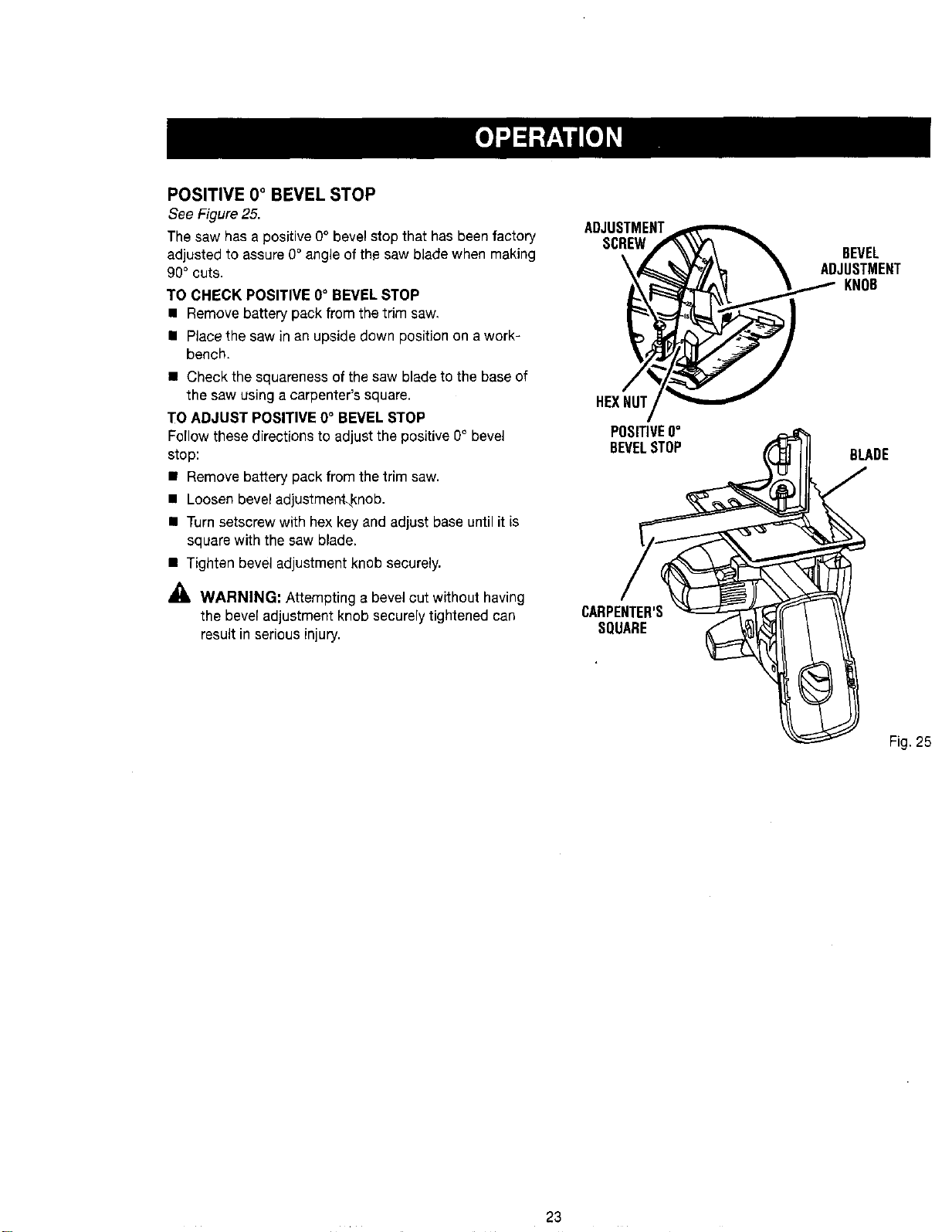
POSITIVE 0° BEVEL STOP
See Figure25.
The saw has a positive 0° bevel stop that has been factory
adjustedto assure0° angleof the saw blade when making
90° cuts.
TO CHECK POSITIVE 0° BEVELSTOP
• Remove battery packfrom thetrim saw.
• Placethe saw in an upsidedownposition on a work-
bench.
• Check thesquareness ofthe saw blade tothe base of
the saw usinga carpenter's square.
TO ADJUST POSITIVE 0° BEVEL STOP
Fo(Iowthesedirectionsto adjustthe positive0° bevel
stop:
• Remove battery pack from the trimsaw.
• Loosenbevel adjustment_knob.
• Turnsetscrew withhex key and adjust base until it is
square with the saw blade.
• Tightenbevel adjustment knob securely.
_lb WARNING: Attempting a bevel cut withouthaving
the bevel adjustmentknobsecurely tightenedcan
resultinseriousinjury.
ADJUSTMENT
SCREW
\
HEXNUT
POSITIVE0°
BEVELSTOP
CARPENTER'S
SQUARE
BEVEL
ADJUSTMENT
KNOB
BLADE
Fig. 25
23

POCKET CUTTING
See Figure 26.
_, WARNING: Always adjust bevel setting to zero
before making a pocket cut. Attempting a pocket
cut at any other setting can result in loss of control
of the saw possibly causing serious injury.
• Remove battery pack fi:omsaw.
• Adjust the bevel setting to zero.
• Set the blade to the correct blade depth setting.
• Place battery pack in saw.
• Swing the lower blade guard up using the lower blade
guard handle.
NOTE: Always raise the lower blade guard with the handle
to avoid serious injury.
• Hold the lower blade guard by the handle.
• Rest the front of the base flat against the workpiece
with the rear of the handle raised so the blade does not
touch the workpiece.
• Start the saw and let the blade reach full speed.
• Guide the saw into the workpiece and make the cut.
_, WARNING: Always cut in a forward direction
when pocket cutting. Cutting in the reverse
direction could cause the saw to climb up on the
workpiece and back toward you.
• Releasethe trigger and allow the blade to come to a
complete stop.
• Lift the saw from the workpiece.
• Clear corners out with a hand saw or sabre saw.
_, WARNING: Never tie the lower blade guard in a
raised position. Leaving the blade exposed could
lead to serious injury.
LOWERBLADEGUARD
POCKETCUT
Fig.26
_IL WARNING= Before performing any adjustment,
make surethe battery pack is removed from tool.
Failureto heed this warning could result in serious
personal injury.
ADJUSTING THE LASER
See Figure 2Z
NOTE: Draw a pencil line on a scrap workpiece parallel to
the long edge of the base as a straight line guide to aid in
the adjusting process.
• Remove battery pack from the trim saw.
• Make sure laser isturned off.
• Remove the laser cover by lifting it off its base.
• Turn laser on.
• Loosen the screw inside laser.
• Rest the front of the base on scrap workpiece.
• Adjust the laser beam with the mark on the scrap
workpiece by loosening the screw to the laser aperture
and slowly moving laser guide left or right.
• Place battery pack in saw.
• Since blade thicknesses vary,always make a trial cut in
scrap workpiece to ensure an accurate cut.
• Once alignment is achieved, tighten the screw.
• Replace the laser cover.
• Check for proper alignment.
• Repeat as necessary until laser is aligned.
SCREW
24
PENCILLINE
LONGEDGE
OFBASE
Fig. 27
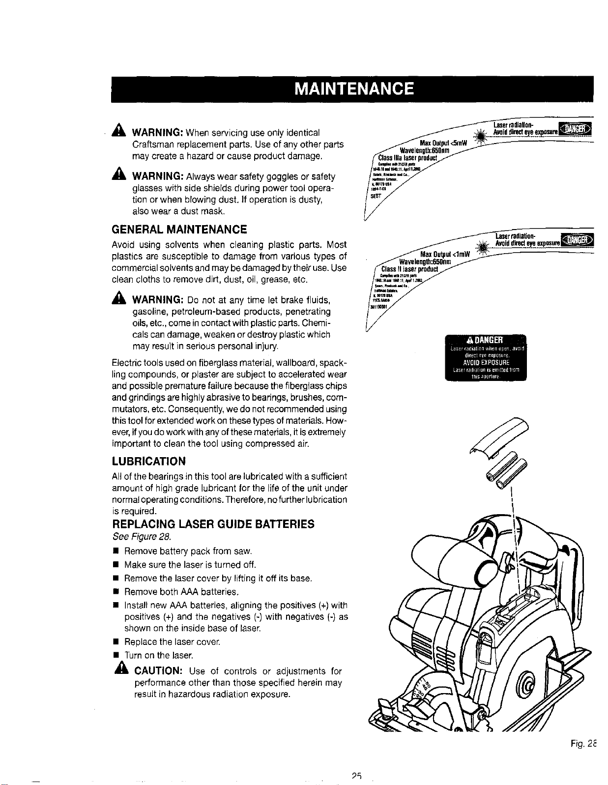
• _1, WARNING: When servicing use only identical
Craftsman replacement parts. Use of any other parts
may create a hazard or cause product damage.
_. WARNING: Always wear safety goggles or safety
glasses with side shields during power tool opera-
tion or when blowing dust. ]foperation is dusty,
also wear a dust mask.
GENERAL MAINTENANCE
Avoid using solvents when cleaning plastic parts. Most
plastics are susceptible to damage from various types of
commercial solvents and may be damaged bytheir use. Use
clean cloths to remove dirt, dust, oil, grease, etc.
_. WARNING: Do not at any time let brake fluids,
gasoline, petroleum-based products, penetrating
oils,etc., come incontact with plasticparts.Chemi-
cals candamage, weaken or destroy plastic which
may result in serious personal injury.
Electric tools used on fiberglass material,wallboard, spack-
ling compounds, or plaster are subject to accelerated wear
and possible premature failure because the fiberglass chips
and grindings are highlyabrasive to bearings, brushes, com-
mutators, etc. Consequently,we do notrecommended using
this tool forextended work on these types ofmaterials. How-
ever,ifyoudo work with anyofthese materials, itisextremely
imporLantto clean the tool using compressed air.
LUBRICATION
All of the bearings in this tool are lubricated with a sufficient
amount of high grade lubricant for the life of the unit under
normaloperating conditions. Therefore,nofurther lubrication
is required.
REPLACING LASER GUIDE BATTERIES
See Figure 28.
• Remove battery pack from saw.
• Make sure the laser is turned off.
• Remove the laser cover by lifting it off its base.
• Remove both AAA batteries.
• Install new AAA batteries, aligning the positives (+)with
positives (+) and the negatives (-) with negatives (-) as
shown on the inside base of laser.
• Replace the laser cover.
• Turn on the laser.
CAUTION: Use of controls or adjustments for
performance other than those specified herein may
result in hazardous radiation exposure.
Laserradlallon-
ALa_iddirecteyee_po,_te_
_k_l_21t, rq_
v,dm=l eeJiS.
,%%-,
_ IJser tadlNon-
Avoiddirecteyeexposure_
ClassFIlaserproduct
_im mll _CFR_
Fig. 2_
_5
BATTERIES
The battery pack for this tool is equipped with nickel-cad-
mium rechargeable batteries. Length of service from each
charging will depend on the type of work you aredoing.
The batteries in this tool have been designed to provide
maximum trouble-free life. However, like all batteries, they
will eventually wear out. Do not disassemble battery pack
and attempt to replace the batteries. Handling of these
batteries, especially when wearing rings and jewelry, could
result in a serious burn.
Toobtain the longest possible battery life, we suggest the
following:
• Remove the battery pack from the charger once it is
fully charged and ready for use.
For battery pack storage longer than 30 days:
• Store the battery pack where the temperature is below
80°F.
• Store battery packs in a "discharged" condition.
BATTERY PACK REMOVAL AND
PREPARATION FOR RECYCLING
To preserve natural resources, please
recycle or dispose of batteries properly.
This product contains nickel-cadmium
batteries. Local, state orfederal
laws may prohibit disposal of nickel-
cadmium batteries in ordinary trash.
Consult your localwaste authority for information
regarding available recycling and/or disposal options.
_, WARNING: Upon removal, cover the battery pack's
terminals with heavy duty adhesive tape. Do not
attempt to destroy or disassemble battery pack or
remove any of its components. Nickel-cadmium bat-
teries must be recycled or disposed of properly. Also,
never touch both terminals with metal objects and/or
body parts as short circuit may result. Keep away
from children. Failureto comply with these warnings
could result in fire and/or serious injury.
Look for these accessories at Sears retail:
• 5-1/2 in. Thin Kerr Blade
_1, WARNING; Current attachments and accessories available for usewith this tool are listed above. Do not use
any attachments or accessories not recommended by the manufacturer of this tool. The use of attachments or
accessories not recommended can result in serious personal injury.
26
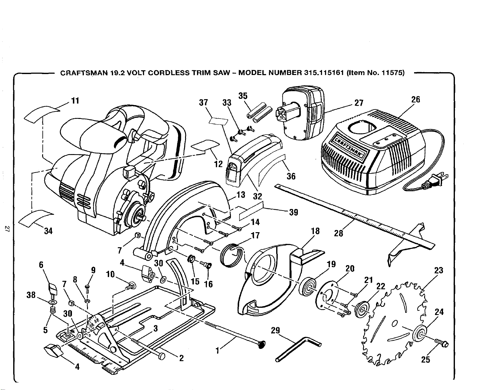
CRAFTSMAN 19.2 VOLT CORDLESS TRIM SAW - MODEL NUMBER 315.115161 (Item No. 11575)
37 33 35 27
26
I
I
I
I
34
6
5
9
7
2
12
32
36
39
18
28
19 20
16 21
22
23
24
25
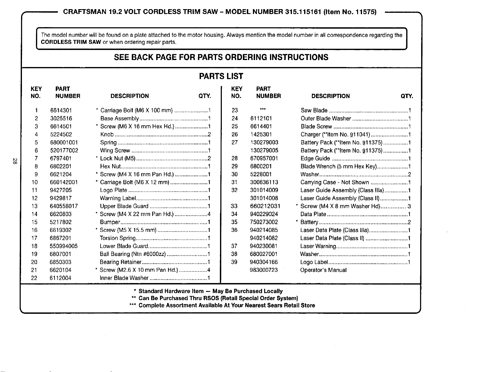
CRAFTSMAN 19.2 VOLT CORDLESS TRIM SAW - MODEL NUMBER 315.115161 (Item No. 11575)
I The model number will be found on a plate attached to the motor housing. Always mention the model number in all correspondence regarding the I
1
CORDLESS TRIM SAW or when ordering repair parts.
J
SEE BACK PAGE FOR PARTS ORDERING INSTRUCTIONS
PARTS LIST
KEY PART
NO. NUMBER DESCRIPTION QTY.
1 6614301
2 3025516
3 6614501
4 5224502
5 680001001
6 520177002
7 6797401
8 6802201
9 6621204
10 660142001
11 9427205
12 9429817
13 640556017
14 6620803
15 5217802
16 6619302
17 6867201
18 550994005
19 6807001
20 6850303
21 6620104
22 6112004
* Carriage Bolt (M6 X 100 mm) ......................1
BaseAssembly ............................................ 1
* Screw (M6X 16 mm Hex Hd.).....................1
Knob ............................................................ 2
Spring .......................................................... 1
Wing Screw ................................................. 1
* Lock Nut (M5).............................................. 2
Hex Nut........................................................ 1
* Screw (M4 X 16 mm Pan Hd.) .....................1
* Carriage Bolt (M6 X 12 mm) ........................ 1
Logo Plate................................................... 1
Warning Label..............................................1
Upper Blade Guard .....................................1
* Screw (M4 X 22 mm Pan Hd.).....................4
Bumper ........................................................1
* Screw (M5X 15.5 mm) ................................ 1
Torsion Spring.............................................. 1
Lower Blade Guard...................................... 1
Ball Bearing (Ntn #6000zz).......................... 1
Bearing Retainer.......................................... 1
* Screw (M2.6 X 10 mm Pan Hd.) ..................4
Inner Blade Washer ..................................... 1
KEY PART
NO. NUMBER
3 *_*
24 6112101
25 6614401
26 1425301
27 130279003
130279005
28 670957001
29 6800201
30 5228001
31 300636113
32 301014009
301014008
33 660212031
34 940229024
35 750273002
36 940214085
940214082
37 940230081
38 680027001
39 940304166
983000723
DESCRIPTION QTY.
Saw Blade ...................................................1
Outer Blade Washer ....................................1
Blade Screw ................................................ 1
Charger (**item No. 9_11041)........................1
Battery Pack (**item No. 9_11375)................1
Battery Pack (**ItemNo. 9_11375)................1
Edge Guide ................................................. 1
Blade Wrench (5 mm Hex Key)....................1
Washer......................................................... 2
Carrying Case - Not Shown ........................1
Laser Guide Assembly (Class Ilia)...............1
LaserGuide Assembly (Class II)..................1
Screw (M4 X 8 mm Washer Hal)............... 3
Data Plate.................................................... 1
Battery......................................................... 2
Laser Data Plate (Class Ilia).........................1
Laser Data Plate (Class II) ...........................1
LaserWarning.............................................. 1
Washer......................................................... 1
Logo Label................................................... 1
Operator's Manual
* Standard Hardware Item - May Be Purchased Locally
** Can Be Purchased Thru RSOS (Retail Special Order System)
*** Complete Assortment Available At Your Nearest Sears Retail Store

Get it fixed, at your home or ours!
Your Home
For repair-in your home-of all major brand appliances,
lawn and garden equipment, or heating and cooling systems,
no matter who made it, no matter who sold it!
For the replacement parts, accessories and
owner's manuals that you need to do-it-yourself.
For Sears professional installation of home appliances
and items like garage door openers and water heaters
1-800-4-MY-HOME ® (1-800469-4663)
Call anytime, day or night (U S A and Canada)
www.sears.com www.sears.ca
Our Home
For repair of carry-in items like vacuums, lawn equ=pment,
and electronics, call or go on-line for the location of your nearest
Sears Parts & Repair Center.
1-800-488-1222
Call anytime, day or night (U S A. only)
www.sears,com
To purchase a protection agreement (U.S.A.)
or maintenance agreement (Canada) on a product serviced by Sears:
1-800-827-6655 (u.sA.) 1-800-361-6665 (Canada)
Para ped_r serv_cto de reparac_6n
a dornicd_o, y para ordenar piezas.
l"888-SU'HOGAR _'
(1-888-784-6427)
Au Canada pour service en franga_s
1-800-LE-FOYER Mc
(1-800-533-6937)
www sears ca
Sears
SM
® Registered Trademark / Trademark / Service Mark of Sears Roebuck and Co
® Maroa Reglstrada ! TU Matca de Fabnca / s_ Marca de Se_lcJe de Sears, Roebuck and Co
MC MD
Marque de commerce I Marque d_posee de Sears, Roebuck and Co
© Sears Roebuck and Co
960001159-01fB)