Loading ...
Loading ...
Loading ...
4
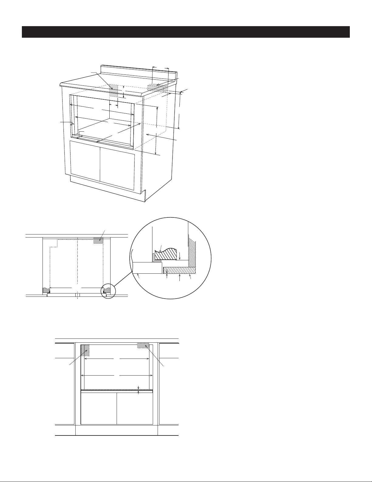
24" MICROWAVE DRAWER FLUSH MOUNT AND MEASUREMENTS
C
N
H
E
F
D
A
B
J
L
I
M
K
G
Prepare cabinet opening as shown in Figures 5, 6, 7
C
L
Top view
A
Anti-Tip block
Mounting cleat
B
C
Drawer face
Cabinet
face
Note: the mounting surface of the finished cleat must
sit 1
17
/32" (38.89 mm) back from the face of the cabinet.
Figure 5
Figure 6
A. 6" (152.40 mm)
B. Suggested electrical outlet location
C. Anti-Tip block
D. 5" (127 mm)
E. 3
1
/2" (88.90 mm)
F. 4" (101.60 mm)
G. 23
7
/8" (606.43 mm)
H. 14
13
/16" (376.24 mm) to bottom of Anti-Tip block
I. 1
17
/32" (38.89 mm)
J. 23
1
/2" (596.90 mm) minimum depth
K. 22
1
/8" (561.98 mm)
L. 1
17
/32" (38.89 mm) to front of shelf
M . 16
1
/4" (412.75 mm) opening
N. Floor must support 100 lb (45.4 kg)
A. 22
1
/8" (596.98 mm) mounting cleat opening width
B. 0" ush
C. 1
17
/32" (38.89 mm) front of cleat to cabinet face
C
Front view
No oven shown
B
A
Suggested electrical
outlet location
Anti-Tip block
Figure 7
A. 22
1
/8" (561.98 mm) mounting cleat opening width
B. 23
7
/8" (606.43 mm) ush opening width
C.
1
/8" (3.17 mm) from opening to top of shelf
Loading ...
Loading ...
Loading ...