Loading ...
Loading ...
Loading ...
determine the requisite air vent
requirements.
Location
The hob may be located in a kitchen, a
kitchen/diner or bed sitting room (with a
volume greater than 20 m³), but not in a
bathroom or shower room.
The minimum distance combustible
material can be fitted above the hob in
line with the edges of the hob is 400 mm.
If it is fitted below 400 mm a space of 50
mm must be allowed from the edges of
the hob.
3.3 Gas Connection
WARNING!
Any gas installation must be
carried out by a GAS SAFE
REGISTER installer.
Make sure that, once the hob is installed,
it is easily accessible for the engineer in
the event of a breakdown.
The manufacturer will not accept liability,
should the above instructions or any of
the other safety instructions incorporated
in this instruction booklet be ignored.
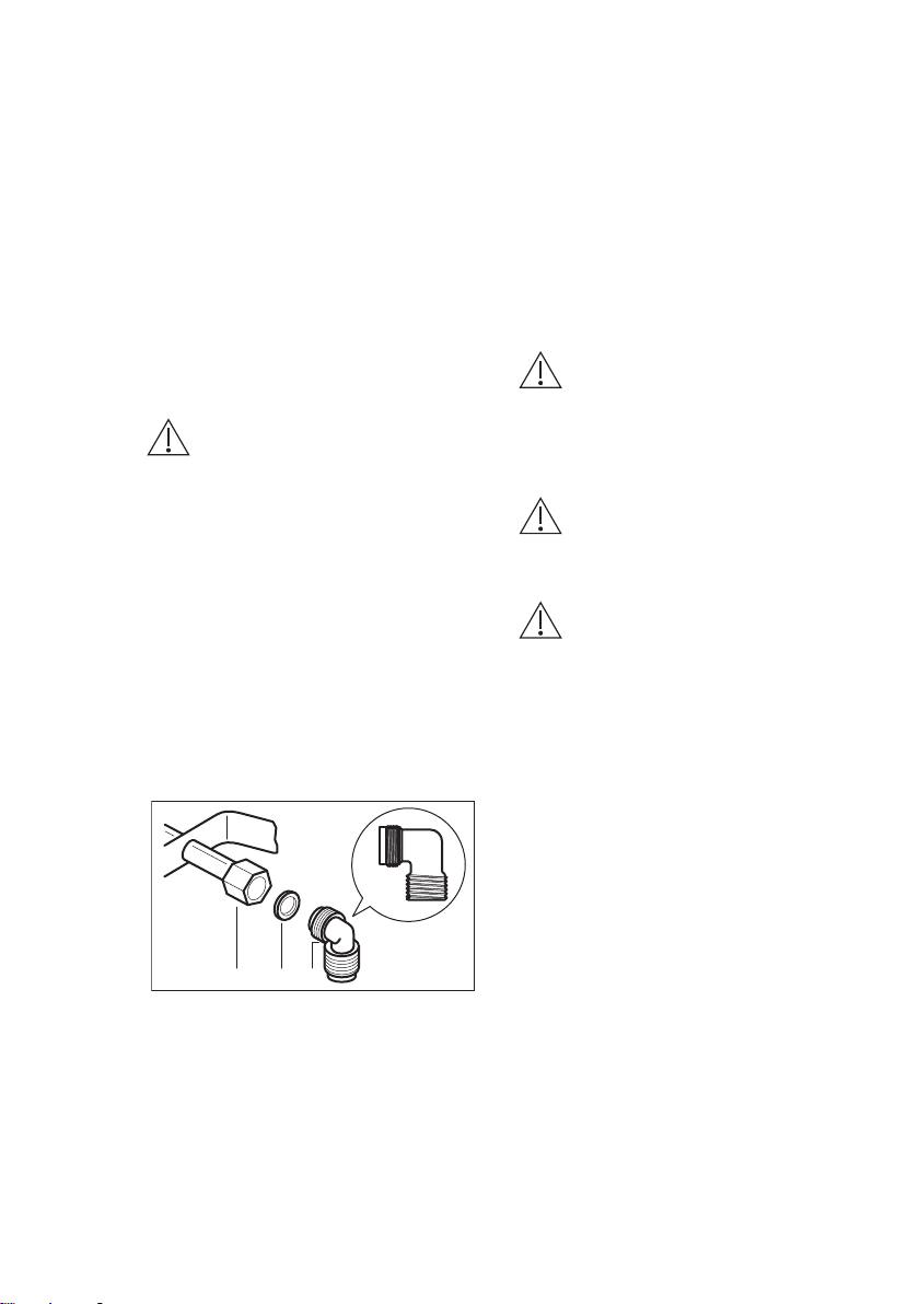
On the end of the shaft, which includes
the G 1/2" threaded elbow, adjustment is
fixed so that the washer is fitted between
the components as shown in the
diagram. .
1/2
1/2
A B C
A. End of shaft with nut
B. Washer supplied with the appliance
C. Elbow supplied with the appliance
Connection to the gas supply should be
with either rigid or semi-rigid pipe, i.e.
steel or copper.
The connection should be suitable for
connecting to R 1/2 (1/2 BSP male
thread).
When the final connection has been
made, it is essential that a thorough leak
test is carried out on the hob and
installation.
Make sure that the main connection pipe
does not exert any strain on the hob.
If you use flexible metal pipes make sure
that they agree to ISO 10380 and ISO
10807 standards. Be careful they do not
come in touch with mobile parts or they
are not squeezed. Also be careful when
the hob is put together with an oven.
CAUTION!
It is important to install the
elbow correctly, with the
shoulder on the end of the
thread, fitted to the hob
connecting pipe.
CAUTION!
Failure to ensure the correct
assembly will cause leakage
of gas.
CAUTION!
Make sure that the gas
supply pressure of the
appliance obeys the
recommended values.
Rigid connection:
Carry out connection by using metal rigid
pipes (copper with mechanical end).
3.4 Injectors replacement
1. Remove the pan supports.
2. Remove the caps and crowns of the
burner.
3. With a socket spanner 7 remove the
injectors and replace them with the
ones which are necessary for the
type of gas you use (see table in
"Technical Data" chapter).
4. Assemble the parts, follow the same
procedure backwards.
5. Attach the label with the new type of
gas supply near the gas supply pipe.
You can find this label in the package
supplied with the appliance.
If the supply gas pressure is changeable
or different from the necessary pressure,
you must fit an applicable pressure
adjuster on the gas supply pipe.
ENGLISH 9
Loading ...
Loading ...
Loading ...