CONTENTS
SAFE_
important Safety instructions .........................2, 3, 17-20
Anti-Tip Device ...............................................................2, 3, 12, t8
IIHSTALLAYtlOH .........................................2-16
Dimensions and Clearances ........................................ 2
Gas Pipe and Electric Outlet Locations ................ 5-8
Electrical Connections .......................................................7-8
How to Convert the Range
for Use with LP Gas or Natural Gas ....................13-16
Installing the Anti-Tip Device ..............................................12
USIE AND CARE
Features of Your Range ................................................ 21
Surface Cooking .................................................................22, 23
Using "four Oven ................................................................24-26
Clocks and Timers .......................................................................27
Baking ..................................................................................28, 29
Roasting ..................................................................................30
Roasting Guide ....................................................................3t
Broiling ............................................................................... 32
Broiling Guide .......................................................................33
Care and Cleaning ..........................................................34-42
SERVICE
Problem Solver .................................................................................43
WARRANTY ........................................... back cover
MODELS
61011 61018 61111
61118 61211 61218
7'1221 71228 71321
71328 71631 7'1638
7172'I 7'1728 71821
71828 72711 727'18
72725
Kenmope
/i:
WAFINmNG:if the informationin
this manual is not followed
exactly,a fire or explosion may
resuJtcausingproperbjdamage,
personalinjuryor death.
--Do not store or use gasoline or
other ftammabnevapors and liquids
in the vicinity of this or any other
appliance,
--WHAT TO DOiFYOU SMELLGAS
o Do not try to light any appfiance.
o Do not touch any electrical switch;
do not use any phone in your
buiBding.
• immediately call your gas supplier
from a neighbor's phone. Follow
the gas supplier's instructions.
oIf you cannot reach your gas sup=
plier, call the fire department.
--_nstallation and service must be
performed by a qualified installer,
service agency or the gas supplier.
mNSTALLAT ON UNSTRUCTgONS
BEFORE YOU BEGIN
Read these instructions completely and carefully.
IMPORTANT: Save these instructions for the local
electrical inspector's use.
INSTALLER: Leave these instructions with the
appliance after installation is completed.
OWNER: Keep this Use and Care Guide and the
Installation Instructions for future use. This appli-
ance must be properly grounded.
CAUTION
Do not attempt to operate the oven of this range
during a power failure.
IMPORTANT
Remove all packing material and literature from
oven before connecting gas and electrical supply
to range.
,_ WARNaNG
ALL RANGES CAN TIP.
oINJURY TO PERSONS
COULD RESULT.
oINSTALL THE ANTI-TIP
DEVICE PACKED WITH
THE RANGE.
oSEE THE INSTALLATION
INSTRUCTIONS,
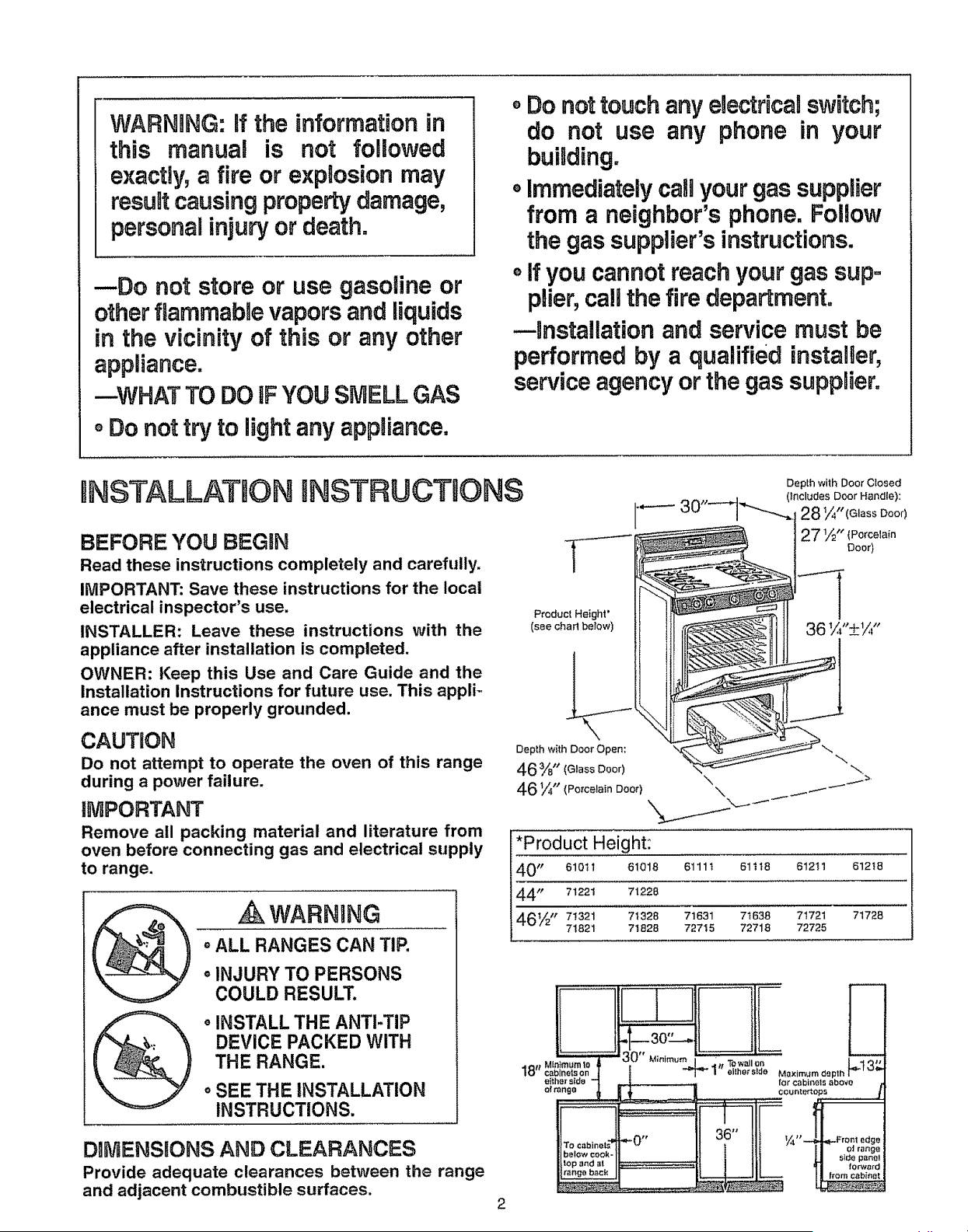
D_MENSgONS AND CLEARANCES
Provide adequate clearances between the range
and adjacent combustible surfaces.
Product Height"
(see chad below)
Depth with Door Open:
46 %" (Glass Door)
46 ¼" (Porcelain Door)
i'Product Height:
40 tp 61011 61018 61111 61118 61211 61218
44,P 71221 71228
46½_ 71321 71328 71631 71638 71721 71728
71821 71828 72715 72718 72725
2
18"
30"
'_}mum 10 Minimum
_Inets on
"_e_'side
elrange
, ,-p
TO cab=nets :
below cook-
lop end at
range bach
t ........ ,, ,,,,,,v,,
q_**0 rt
m
36"
._. Towallon LI _"
"_ / eilhet sldo Mexim_m deplh I"_' _
forcabinets above j
countert_
_'_" I_ ' ' --_-FrOnt edge
| I I eJ range
1 _LI Side panel
/ _1 torward
I | ltorn cabinet
OMPORTANT SAFETY NSTRUCTBONS
o Installation of this range must conform with local
codes, or in the absence of local codes, with
the National Fuel Gas Code, ANSi Z223.1, latest
edition.
This range has been design-certified by the American
Gas Association according to ANSI Z21°1, latest edi-
tion. As with any appliance using gas and generating
heat, there are certain safety precautions you should
follow. You will find these precautions at the beginning
of the Use and Care section of this book. Read them
carefully,
o Have your range installed by a qualified installer or
service technician_
o Your range must be electrically grounded in accor-
dance with local codes or, in the absence of local
codes, in accordance with the National Electrical
Code (ANSt!NFPA 70, latest edition). See Electrical
Connections in this section,
o Before installing your range on linoleum or any other
synthetic floor covering, make sure the floor covering
can withstand 180°F. without shrinking, warping or
discoloring. Do not install the range over carpeting
unless a sheet of 1/4" thick plywood or similar insu_
lator is placed between the range and carpeting
° Make sure the wall coverings around the range can
withstand heat generated by the range up to 200°E
oAvoid placing cabinets above the range. To reduce
the hazard caused by reaching over the open flames
of operating burners, instalt a ventilation hood over
the range that projects forward at least 5" beyond
the front of the cabinets.
oThe ventilating hood must be constructed of sheet
metal not less than 00122" thick_ Install above the
cooking top with a clearance of not less than 1/4"
between the hood and the underside of the com-
bustible material or metal cabinet. The hood must be
at least as wide as the appliance and centered over
the appliance. Clearance beb_veen the cooking sur-
face and the ventilation hood surface iVlUST NEVER
BE LESS THAN 24 INCHES.
o if cabinets are placed above the range, allow a mini-
mum clearance of 30" between the cooking surface
and the bottom of unprotected cabinets..
o If a 30" clearance between cooking surface and
overhead combustible material or metal cabinets
cannot be maintained, protect the underside of the
cabinets above the cooking top with not less than
1/4" insulating millboard covered with sheet metal
not less than Q0122" thick_
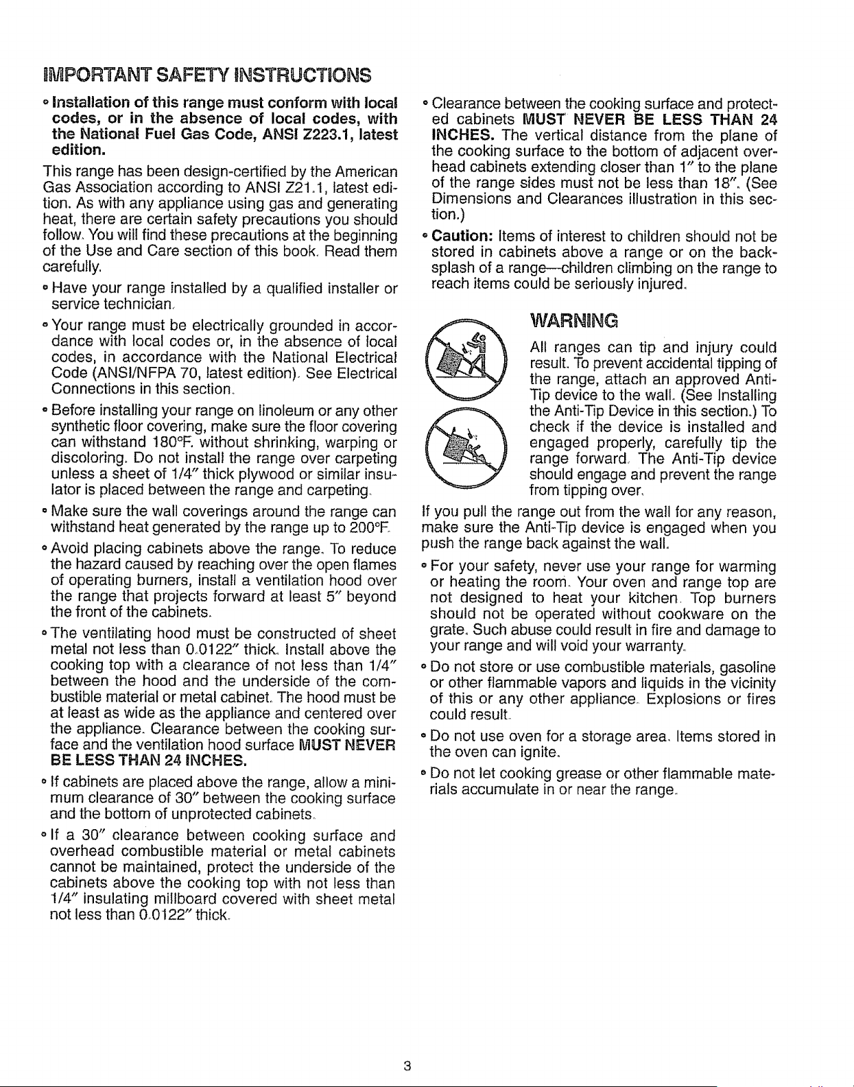
oClearance between the cooking surface and protect-
ed cabinets MUST NEVER BE LESS THAN 24
INCHES. The vertical distance from the plane of
the cooking surface to the bottom of adjacent over-
head cabinets extending closer than 1" to the plane
of the range sides must not be less than 18". (See
Dimensions and Clearances illustration in this sec-
tion.)
o Caution: Items of interest to children should not be
stored in cabinets above a range or on the back-
splash of a range--children climbing on the range to
reach items could be seriously injured.
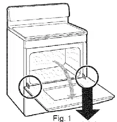
WARNING
All ranges can tip and injury could
result. To prevent accidental tipping of
the range, attach an approved Anti-
Tip device to the wall. (See Installing
the Anti-Tip Device in this section..) To
check if the device is installed and
engaged properly, carefully tip the
range forward. The Anti-Tip device
should engage and prevent the range
from tipping over,
If you pull the range out from the wall for any reason,
make sure the AntFTip device is engaged when you
push the range back against the wallo
o For your safety, never use your range for warming
or heating the room. Your oven and range top are
not designed to heat your kitchen. Top burners
should not be operated without cookware on the
grate° Such abuse could result in fire and damage to
your range and will void your warranty..
o Do not store or use combustible materials, gasoline
or other flammable vapors and liquids in the vicinity
of this or any other applianceo Explosions or fires
could result.
. Do not use oven for a storage area, Items stored in
the oven can ignite.
o Do not let cooking grease or other flammable mate-
rials accumulate in or near the range.
BnstaHationInstructions
GENERAL
oSee Dimensions and Clearances in this section for
all rough-in and spacing dimension& These dimen-
sions must be met for safe use of your range. The
location of the electrical outlet and pipe opening (see
Gas Pipe and Electric Outlet Locations) may be
adjusted to meet specific requirements..
oThe range may be placed with 0" clearance (flush)
at the back wall and side walls of the range.,
LOCATION
Do not locate the range where it may be subject to
strong draft& Any openings in the floor or wall behind
the range should be sealed. Make sure the openings
around the base of the range that supply fresh air for
combustion and ventilation are not obstructed by car-
peting or woodwork..
PROTECT YOUR FLOOR
",(our range, like many other household items, is heavy
and can settle into soft floor coverings such as cush-
ioned vinyl or carpeting° Use care when moving the
range on this type of flooring. It is recommended that
the following simple and inexpensive instructions be
followed to protect your floor..
The range should be installed on a sheet of plywood
(or similar material). When the floor covering ends at
the front of the range, the area that the range will rest
on should be built up with plywood to the same level
or higher than the floor covering. This will allow the
range to be moved for cleaning or servicing..
MODEL AND SERIAL NUMBER LOCATION
Depending on your range, you'll find the model and
serial numbers on a label on the front frame of the
range, behind the storage drawer, broiler drawer or
kick panel (depending on model).
TOOLS YOU WiLL NEED
• Phillips and flat-blade screwdrivers
o Pencil and ruler
° Two pipe wrenches (one for backup)
o 1%" open-end or adjustable wrench
o Nut drivers or wrenches: 3/16" and t/4"
ADDITIONAL MATERIALS YOU MAY NEED
Q
O
Gas line shut-off valve
Pipe joint sealant or UL-approved pipe thread tape
with Teflon* that resists action of natural and LP
gases
° Flexible metal appliance connector (I/2" ].D.)_ A 5-
foot length is recommended for ease of installation
but other lengths are acceptable. Never use an old
connector when installing a new ranger
o Flare union adapter for connection to gas supply line
(3/4" or t/2" NPT x 1t2" IoD.)
, Flare union adapter for connection to pressure regu-
lator on range (1/2" NPT x 1/2" ID.)
*Teflon: Registered trademark of DuPont
PREPARATION
o Remove all tape and packaging. Lift up the cooktop
(on models with dual burners) and remove any pack-
ing material under it. Make sure the dual burners are
properly seated and level.
o Remove plastic film that covers some chrome parts
(around oven door, side trim).
oTake the accessory pack out of the oven.,
oCheck to be sure that no range parts have come
loose during shipping..
4
St®p I
Provide Adequate Gas Supply
Your range is designed to operate at a pressure of
4" of water column on natural gas or, if designed for
LP gas (propane or butane), 10" of water column.
Make sure you are supplying your range with the type
of gas for which it is designed This range is convert-
ible for use on natural or propane gas, if you decide to
use this range on a different type of gas, conversion
adjustments must be made by a service technician or
other qualified person before attempting to operate
the range on that gas.
For proper operation, the pressure of natural gas sup-
plied to the regulator must be between 4" and 13" of
water column. For LP gas, the pressure supplied must
be between 10" and 13" of water column. When
checking for proper operation of the regulator, the inlet
pressure must be at least 1" greater than the operat-
ing (manifold) pressure as given above The pressure
regulator located at the inlet of the range manifold
must remain in the supply line regardless of whether
natural or LP gas is being used.. A flexible metal appli-
ance connector used to connect the range to the gas
supply line should have an 1..D.of 1/2" and be 5 feet in
length for ease of instatlation.
2
Connect the Range to Gas
Shut off the main gas supply valve before disconnect-
ing the old range and leave it off until new hook-up
has been completed. Don't forget to relight the
pilot on other gas appliances when you turn the gas
back on.
Because hard piping restricts movement of the range,
the use of an AG.A.-certified flexible metal appliance
connector is recommended unless local codes require
a hard-piped connection. Never use an old connector
when installing a new range.. If the hard piping method
is used, you must carefully align the pipe; the range
cannot be moved after the connection is made.
To prevent gas leaks, put pipe joint compound on, or
wrap pipe thread tape with Teflon* around, all male
(external) pipe threads.
*Teflon: Registered trademark of DuPont
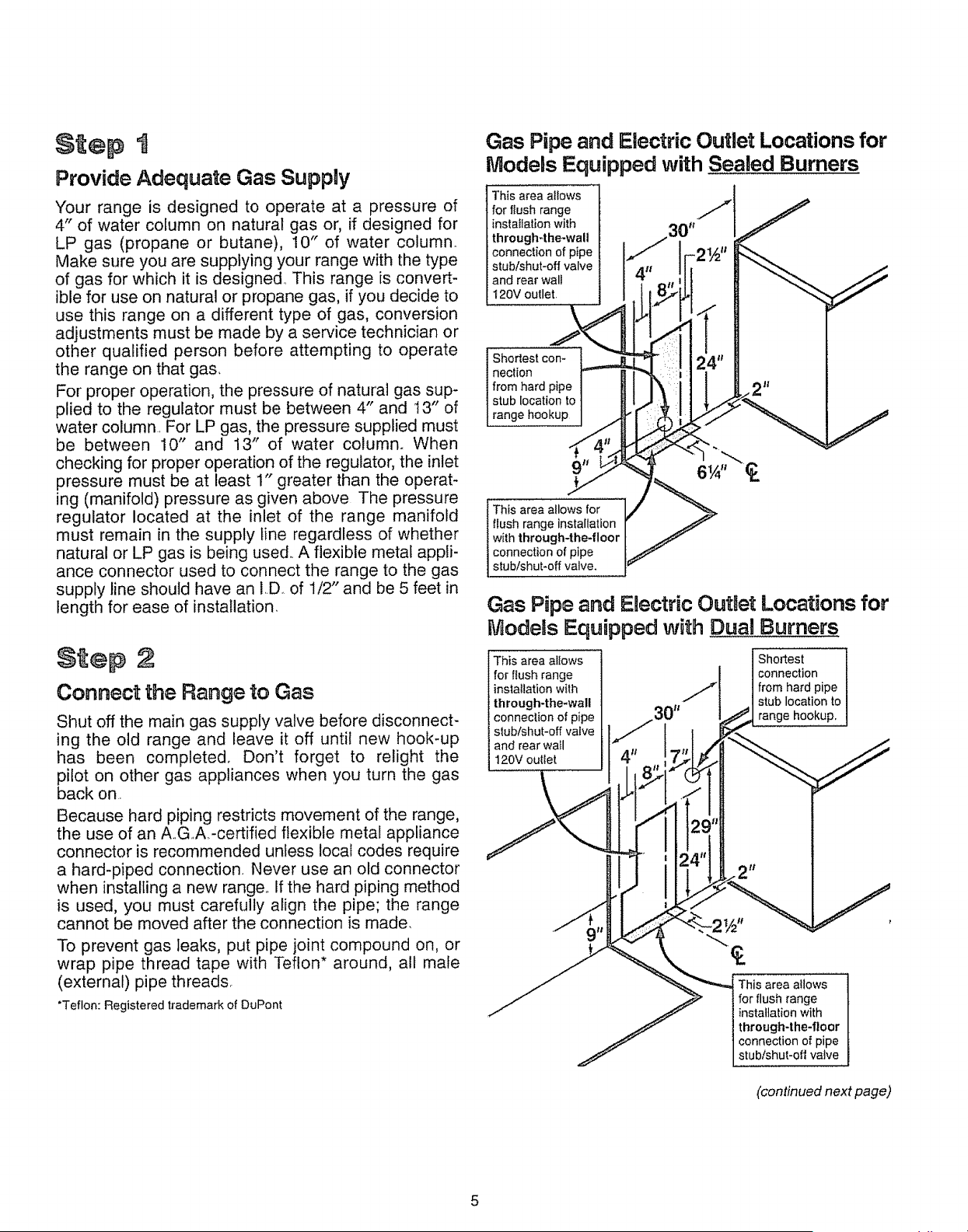
Gas Pipe and Electric Outlet Locations for
Models Equipped with Sealed Burners
This area allows
for flush range
installation with
through-the-walt
connection of pipe
stub/shut-off valve
and rear wall
I20V outlet.
Shortest con-
nection
I from hard pipe
stub location to
[ range hookup
This area allows for
flush range installation
with through-the-floor
connection of pipe
stub/shut*off valve.
Gas Pipe and ERectric OutEet Locations for
Models Equipped with Dual Burners
This area allows
for flush range
installation with
through-the*wall
connection of pipe
stub/shut-off valve
and rear wall
120V outiet
Shortest
connection
from hard pipe
stub location to
range hookup,
This area allows
for flush range
installation with
through-the-floor
connection of pipe
stub/shut-off valve
(continued next page)
5
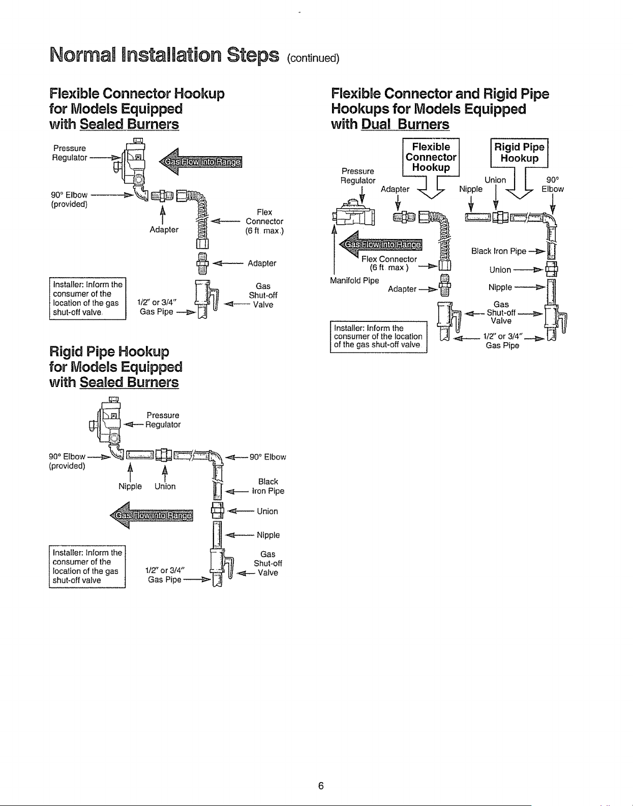
Normal Installation Steps (continued)
Flexible Connector Hookup
for Models Equipped
with Sealed Burners
Pressure
Regulator
90" Elbow'
(provided)
installer: Inform the
consumer of the
location of the gas
shut-off valve,
p Flex
Connector
Ad te (6ft max,)
@ -,_------ Adapter
Gas
Shuhoff
1t'Z' ot 3/4"
Valve
Gas Pipe _ L_ '_
Rigid Pipe Hookup
for Models Equipped
with Sealed Burners
__]'_ Pressure
-_--- Regulator
90" Elbow _j _ _ __'t _ 90° Elbow
(provided) ,_ _
Black
Nii_ple Union _ <_---- Iron Pipe
r-_ Nipple
]nstaIler: inform the _- _,_ Gas
consumer of the 0 , I _1_|I Shut-off
location of the gas 1/Z or 3/4' _ Ill _ Valve
shut-off valve Gas Pipe _[,jJ _
Flexibge Connector and Rigid Pipe
Hookups for Models Equipped
with Dual Burners
Flexible
Connector
Hookup
6
1. Installa manualgas line shut-offvalve in the gas
line in an easily accessedlocation outside of the
range. Make sure everyoneoperatingthe range
knowswhereandhowto shutoff the gas supplyto
the range_
2. Installmale1/2"flare unionadapterto the 1/2"NPT
internalthreadelbow at inletof pressureregulator.
On models equipped with dual burners, install
the male pipe thread end of the 1/2" flare union
adapter to the 1/2" NPT internal thread at inlet of
pressure regulator, Use a backup wrench on the
regulator fitting to avoid damage.
When installing the range from the front, remove the
90 ° elbow for easier installation
3. Install male 1/2" or 3/4" flare union adapter to the
NPT internal thread of the manual shut-off valve,
taking care to back-up the shut-off valve to keep it
from turning.
4. Connect flexible metal appliance connector to the
adapter on the range° Position range to permit con-
nection at the shut-off valve.
5. When all connections have been made, make sure
all range controls are in the off position and turn on
the main gas supply valve° Use a liquid leak detec-
tor at all joints and connections to check for leaks in
the system.
CAUTION: DO NOT USE A FLAME TO CHECK I
i
FOR GAS LEAKS.
1
When using test pressures greater than 1/2 psig to
pressure test the gas supply system of the residence,
disconnect the range and individual shut-off valve
from the gas supply piping. When using test pres-
sures of i/2 psig or less to test the gas supply sys-
tem, simply isolate the range from the gas supply
system by closing the individual shut-off valve.
Step 3
Electrical Connections (for Models
Equipped with Electric ignition)
Electrical Requirements
120-volt, 60 Hertz, properly grounded branch circuit
protected by a 15-amp or 20-amp circuit breaker or
time delay fuse,,
Extension Cord Cautions
Because of potential safety hazards associated with
certain conditions, we strongly recommend against
the use of an extension cord° However, if you still elect
to use an extension cord, it is absolutely necessary
that it be a ULqisted, 3-wire grounding4ype appliance
extension cord and that the current carrying rating of
the cord in amperes be equivalent to, or greater than,
the branch circuit rating,
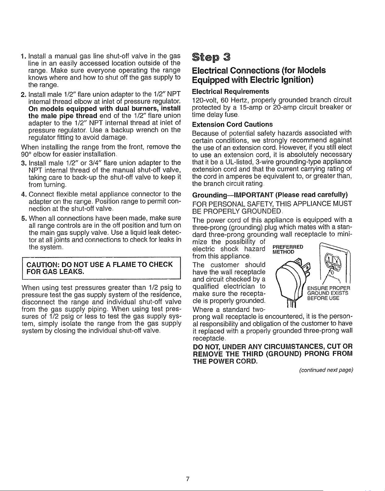
Grounding--IMPORTANT (Please read carefully)
FOR PERSONAL SAFETY, THIS APPLIANCE MUST
BE PROPERLY GROUNDED,
The power cord of this appliance is equipped with a
three-prong (grounding) plug which mates with a stan-
dard three-prong grounding wall receptacle to mini-
mize the possibility of
electric shock hazard
from this appliance
The customer should
have the wall receptacle
and circuit checked by a
qualified electrician to
make sure the recepta-
cle is properly grounded.
Where a standard two-
PREFERRED
METHOD =
prong wall receptacle is encountered, it is the person-
al responsibility and obligation of the customer to have
it replaced with a properly grounded three-prong wall
receptacle_
DO NOT, UNDER ANY CIRCUMSTANCES, CUT OR
REMOVE THE THIRD (GROUND) PRONG FROM
THE POWER CORD.
(continued next page)
7
Normal NnstaHation Steps (continued>
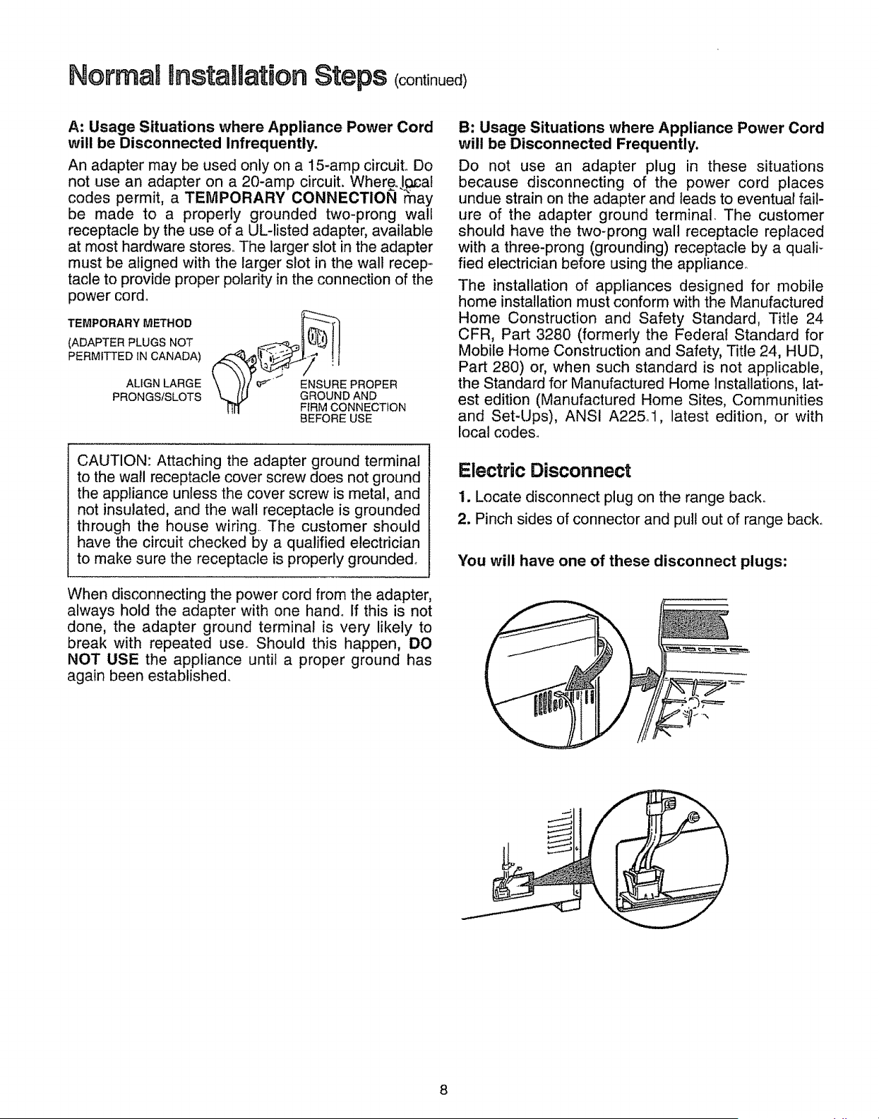
A: Usage Situations where Appliance Power Cord
will be Disconnected Infrequently.
An adapter may be used only on a 15-amp circuiL Do
not use an adapter on a 20-amp circuit. Where,.J_:acat
codes permit, a TEMPORARY CONNECTION may
be made to a properly grounded two-prong wall
receptacle by the use of a UL-listed adapter, available
at most hardware stores. The larger slot in the adapter
must be aligned with the larger slot in the wall recep.o
tacle to provide proper polarity in the connection of the
power cor&
TEMPORARY METHOD __"
(ADAPTER PLUGS NOT
PERMiTTED ,N CANADA)_AUGN LARGE e_' ' FEGf_R_UU_(_DN_NR_cPER
PRONGS/SLOTS N
BEFORE USE
CAUTION: Attaching the adapter ground terminal
to the wall receptacle cover screw does not ground
the appliance unless the cover screw is metal, and
not insulated, and the wall receptacle is grounded
through the house wiring. The customer should
have the circuit checked by a qualified electrician
to make sure the receptacle is properly grounded.
When disconnecting the power cord from the adapter,
always hold the adapter with one hand. If this is not
done, the adapter ground terminal is very likely to
break with repeated use. Should this happen, DO
NOT USE the appliance until a proper ground has
again been established.
B: Usage Situations where Appliance Power Cord
will be Disconnected Frequently.
Do not use an adapter plug in these situations
because disconnecting of the power cord places
undue strain on the adapter and leads to eventual fail-
ure of the adapter ground terminal. The customer
should have the two-prong wall receptacle replaced
with a three-prong (grounding) receptacle by a quali-
fied electrician before using the appliance°
The installation of appliances designed for mobile
home installation must conform with the Manufactured
Home Construction and Safety Standard, Title 24
CFR, Part 3280 (formerly the Federal Standard for
Mobile Home Construction and Safety, Title 24, HUD,
Part 280) or, when such standard is not applicable,
the Standard for Manufactured Home Installations, lat-
est edition (Manufactured Home Sites, Communities
and Set-Ups), ANSI A225ol, latest edition, or with
local codes°
Electric Disconnect
1. Locate disconnect plug on the range back.
2. Pinch sides of connector and pull out of range back.
You will have one of these disconnect plugs:
Step 4
Seal the Openings
Seal any openings in the wall behind the range and
in the floor under the range when hookups are
completed,
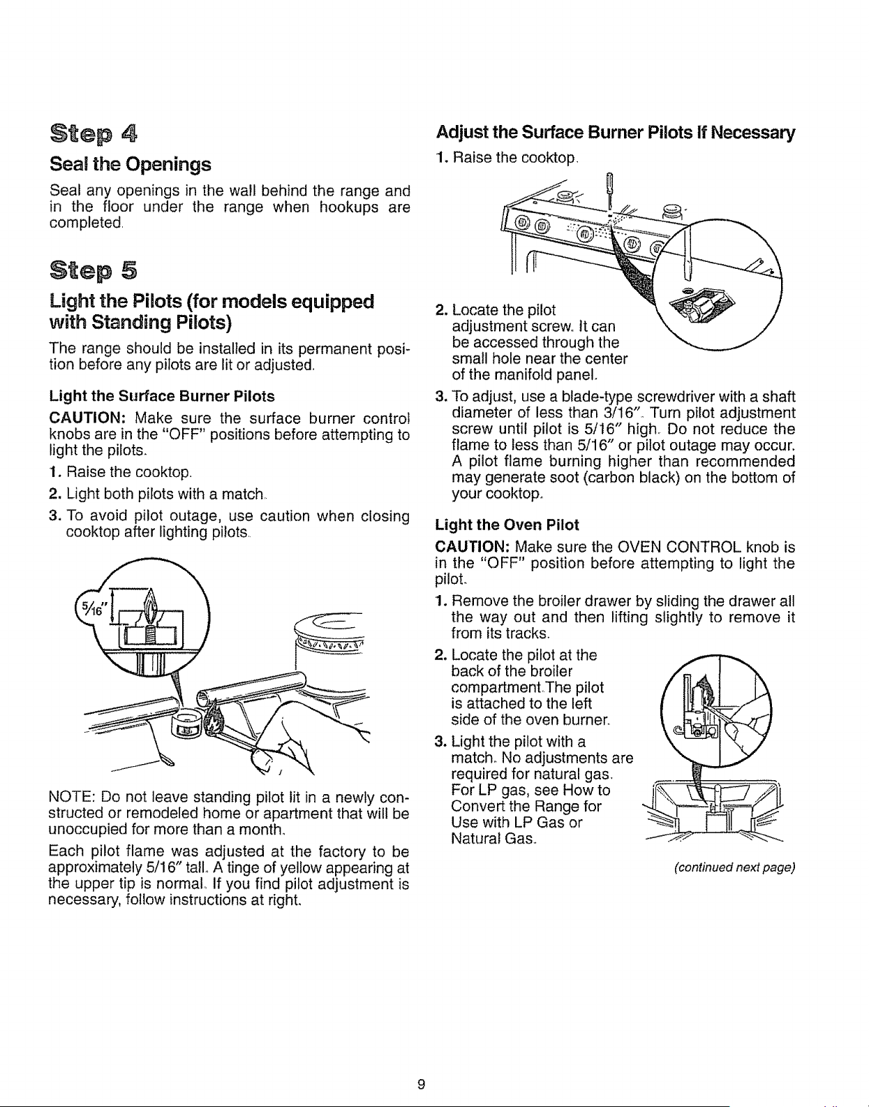
Adjust the Surface Burner Pilots If Necessary
1. Raise the cooktop,
Step 5
Light the Pilots (for models equipped
with Standing Pilots)
The range should be installed in its permanent posi-
tion before any pitots are lit or adjusted.
Light the Surface Burner Pilots
CAUTION: Make sure the surface burner control
knobs are in the "OFF" positions before attempting to
light the pilots.
1. Raise the cooktop.
2. Light both pilots with a match,.
3, To avoid pilot outage, use caution when closing
cooktop after lighting pilots,.
NOTE: Do not leave standing pilot lit in a newly con-
structed or remodeled home or apartment that will be
unoccupied for more than a month,
Each pilot flame was adjusted at the factory to be
approximately 5/16" tatlo A tinge of yellow appearing at
the upper tip is normal° if you find pilot adjustment is
necessary, follow instructions at right,
2_
=
Locate the pilot
adjustment screw° it can
be accessed through the
small hole near the center
of the manifold panel,
To adjust, use a blade-type screwdriver with a shaft
diameter of less than 3/16", Turn pilot adjustment
screw until pilot is 5/16" high, Do not reduce the
flame to less than 5/16" or pilot outage may occur.
A pilot flame burning higher than recommended
may generate soot (carbon black) on the bottom of
your cooktop,
Light the Oven Pilot
CAUTION: Make sure the OVEN CONTROL knob is
in the "OFF" position before attempting to light the
pilot,
1. Remove the broiler drawer by sliding the drawer all
the way out and then lifting slightly to remove it
from its tracks.
2_
8
Locate the pilot at the
back of the broiler
compartmentThe pilot
is attached to the left
side of the oven burner,
Light the pilot with a
match_ No adjustments are
required for natural gas,
For LP gas, see How to
Convert the Range for
Use with LP Gas or
Natural Gas.
(continued next page)
9
Normag nstaHation nnstructions (cont noed)
S'_ep _=_ (continued)
Light The Pilots
Stand-By
4, Turn the OVEN CONTROL knob to a setting above
200°F, The pilot flame will increase in size and
impinge on the temperature-response element° The
oven burner will light in 30-90 seconds°
The oven burner will operate until the set temperature
is reached. The oven burner will continue to cycle on
and off as necessary to maintain the oven at the tem-
perature indicated by the OVEN CONTROL knob
Step G
Check ignition of Surface Burners
Surface Burner mgnition
Operation of all cooktop and oven burners should be
checked after the pilots have been lighted (on some
models) and range and gas supply lines have been
carefully checked for leaks.
Standing Piaot Models
Select a top burner knob and simultaneously push in
and turn to HI position° The burner should light within
a few seconds. Try each burner in succession until all
burners have been checked°
Electric Ignition ModeBs
Select a top burner knob and simultaneously push in
and turn to LITE position. You will hear a snapping
sound indicating proper operation of the spark mod-
ule_ Once the air has been purged from the supply
lines, burners should light within 4 seconds. After
burner lights, rotate knob out of the LITE position° Try
each burner in succession until all burners have been
checked°
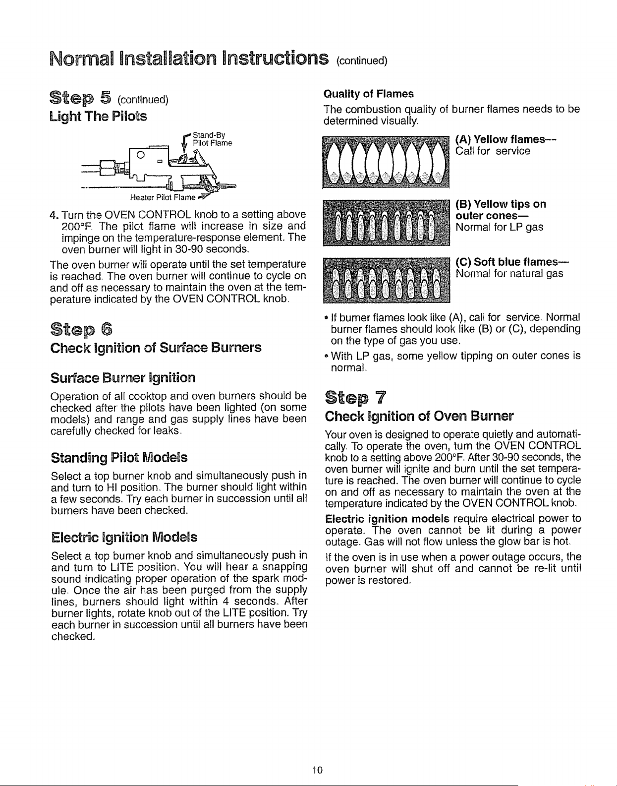
Quality of Flames
The combustion quality of burner flames needs to be
determined visually,
(A) Yellow flames--
Call for service
(B) Yellow tips on
outer cones--
Normal for LP gas
(C) Soft blue flames--
Normal for natural gas
• If burner flames look like (A), call for service. Normal
burner flames should look like (B) or (C), depending
on the type of gas you use.
oWith LP gas, some yellow tipping on outer cones is
normal.
Step 3'
Check ignition of Oven Burner
Your oven is designed to operate quietly and automati-
cally, To operate the oven, turn the OVEN CONTROL
knob to a setting above 200°E After 30-90 seconds, the
oven burner will ignite and burn until the set tempera-
ture is reached, The oven burner will continue to cycle
on and off as necessary to maintain the oven at the
temperature indicated by the OVEN CONTROL knob_
Electric ignition models require electrical power to
operate. The oven cannot be lit during a power
outage. Gas will not flow unless the glow bar is hoL
If the oven is in use when a power outage occurs, the
oven burner will shut off and cannot be re-lit until
power is restored_
I0
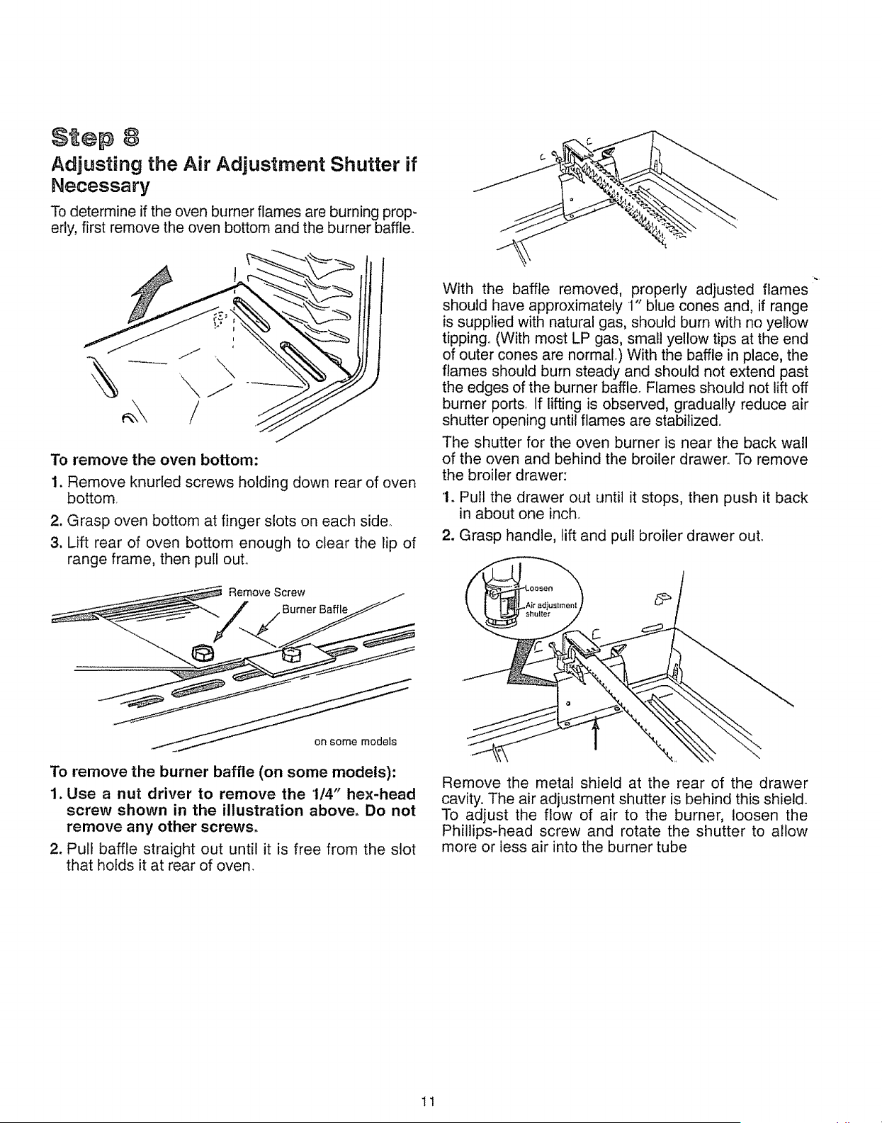
$ ep 8
Adjusting the Air Adjustment Shutter if
Necessary
To determine if the oven burner flames are burning prop-
erly, first remove the oven bottom and the burner baffle.
To remove the oven bottom:
1. Remove knurled screws holding down rear of oven
bottom
2. Grasp oven bottom at finger slots on each side.
3. Lift rear of oven bottom enough to clear the lip of
range frame, then pull out.
Remove Screw
Burner Baffle
With the baffle removed, properly adjusted flames
should have approximately 1" blue cones and, if range
is supplied with natural gas, should burn with no yellow
tipping.. (With most LP gas, small yellow tips at the end
of outer cones are normal,) With the baffle in place, the
flames should burn steady and should not extend past
the edges of the burner baffle. Flames should not lift off
burner ports. If lifting is observed, gradually reduce air
shutter opening until flames are stabilized,
The shutter for the oven burner is near the back wall
of the oven and behind the broiler drawer_ To remove
the broiler drawer:
1. Putt the drawer out until it stops, then push it back
in about one inch_
2. Grasp handle, lift and pull broiler drawer out.
on some models
To remove the burner baffle (on some models):
1. Use a nut driver to remove the 1/4" hex-head
screw shown in the illustration above, Do not
remove any other screws.
2. Pull baffle straight out until it is free from the slot
that holds it at rear of oven.
Remove the metal shield at the rear of the drawer
cavity. The air adjustment shutter is behind this shield.
To adjust the flow of air to the burner, loosen the
Phillips-head screw and rotate the shutter to allow
more or less air into the burner tube
11
NormaD installation Bnstructions cont nued
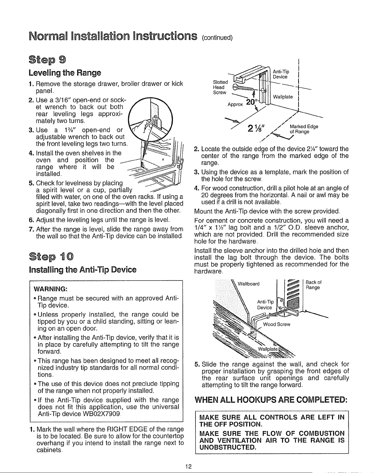
$ :ep 9
Leveling the Range
1. Remove the storage drawer, broiler drawer or kick
panel°
2. Use a 3/16" open-end or sock- ./
et wrench to back out both f t_71 \
rear leveling legs approxi- _' I_
mately two turns, _ __ )
3. Use a 1%' open-end or _ r._.-.._
adjustable wrench to back out ",_ / -':_€"f
the front leveling legs two turns.. __ till II
4, Install the oven shelves in the ro_ !fti It
oveo pos tioothe1-i .. 0
range where it will be _ __j.-<_
5. Check for levelness by placing _.__
a spirit level or a cup, partially
filled with water, on one of the oven racks.. If using a
spirit level, take two readings--with the level placed
diagonally first in one direction and then the other.
6. Adjust the leveling legs until the range is level.
7. After the range is level, slide the range away from
the wall so that the Anti-Tip device can be installed.
t @
Installing the Anti-Tip Device
WARNING:
o Range must be secured with an approved Anti-
Tip device.
o Unless properly installed, the range could be
tipped by you or a child standing, sitting or lean-
ing on an open door,,
• After installing the Anti-Tip device, verify that it is
in place by carefully attempting to tilt the range
forward.
oThis range has been designed to meet all recog-
nized industry tip standards for all normal condi-
tions,,
o The use of this device does not preclude tipping
of the range when not properly installed,
o tf the Anti-Tip device supplied with the range
does not fit this application, use the universal
Anti-Tip device WB02X7909
'1. Mark the walt where the RIGHT EDGE of the range
is to be located. Be sure to allow for the countertop
overhang if you intend to install the range next to
cabinets
Approx 20,
1
_e_:Ant_'ript
;ce !
t!i 'ii'°'eI
/"
,/
/ Marked Edge
,/
2,
3_
4.
,,-f
Locate the outside edge of the device 2W" toward the
center of the range from the marked edge of the
range.
Using the device as a template, mark the position of
the hole for the screw,
For wood construction, drill a pilot hole at an angle of
20 degrees from the horizontal, A nail or awl may be
used if a drill is not available,,
Mount the Anti-Tip device with the screw provided,,
For cement or concrete construction, you will need a
1/4" x 1½" lag bolt and a 1/2" O.D sleeve anchor,
which are not provided,, Drill the recommended size
hole for the hardware.
Install the sleeve anchor into the drilled hole and then
install the lag bolt through the device, The bolts
must be properly tightened as recommended for the
hardware.
Wallboard
Anti-Tip
Device
Wood Screw
Back of
Range
5. Slide the range against the wall, and check for
proper installation by grasping the front edges of
the rear surface unit openings and carefully
attempting to tilt the range forward.
WHEN ALL HOOKUPS ARE COMPLETED:
MAKE SURE ALL CONTROLS ARE LEFT IN
THE OFF POSITION.
MAKE SURE THE FLOW OF COMBUSTION
AND VENTILATION AIR TO THE RANGE IS
UNOBSTRUCTED.
12
How to Convert the Range for Use with LP Gas or NaturaUGas
Prepare Range for Conversion
CAUTION--Before converting the range:
(1) Turn off gas supply at the wall and
(2) Turn off the electrical power to the range.
tf range has not yet been connected to gas supply,
or if flexible connection was made, range may be
pulled out from the wall to make conversion easier.
Tools Required:
T-10 Torxdriver (for sealed burners)
I/2" and 3/4" open-end wrench
Flat blade screwdriver (small)
Nut drivers or wrenches: 7mm or 5/16"
(depending on the size of the spuds)
[
WARNING: Do not remove the pressure regulator from the range
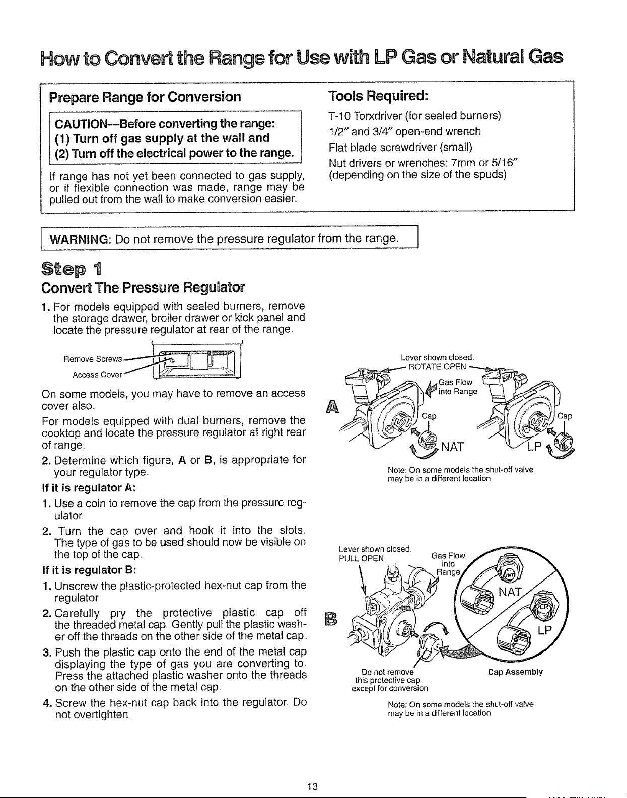
Step t
Convert The Pressure ReguUator
1. For models equipped with sealed burners, remove
the storage drawer, broiler drawer or kick panel and
locate the pressure regulator at rear of the range
Remove Screws __._
Access Cover
On some models, you may have to remove an access
cover also
For models equipped with dual burners, remove the
cooktop and locate the pressure regulator at right rear
of range
2. Determine which figure, A or B, is appropriate for
your regulator type.
If it is regulator A:
1. Use a coin to remove the cap from the pressure reg-
ulator
2, Turn the cap over and hook it into the slots.
The type of gas to be used should now be visible on
the top of the cap.
If it is regulator B:
1. Unscrew the plastic-protected hex-nut cap from the
regulator
2. Carefully pry the protective plastic cap off
the threaded metal cap Gently pull the plastic wash-
er off the threads on the other side of the metal cap
3. Push the plastic cap onto the end of the metal cap
displaying the type of gas you are converting to_
Press the attached plastic washer onto the threads
on the other side of the metal cap
4. Screw the hex-nut cap back into the regulator. Do
not overtighten
Lever shown closed
_ ROTATE OPEN_
Lr__L_" _._ _ _Gas Flow _ ._
A ___.__/_..,)C8_D_ into Range __ _._i / _. _._.4, _Ca p
___ NAT ///____
Note: On some models the shut-otf valve
may be in a different location
Lever shown closed.
PULL OPEN.
\
Gas Flow
into
Do not remove
this protective cap
except for conversion
Cap Assembly
Note: On some models the shut-off valve
may be in a different location
13
Hewto Convert the Rangefor UsewithLPGasor NaturalGas <continued)
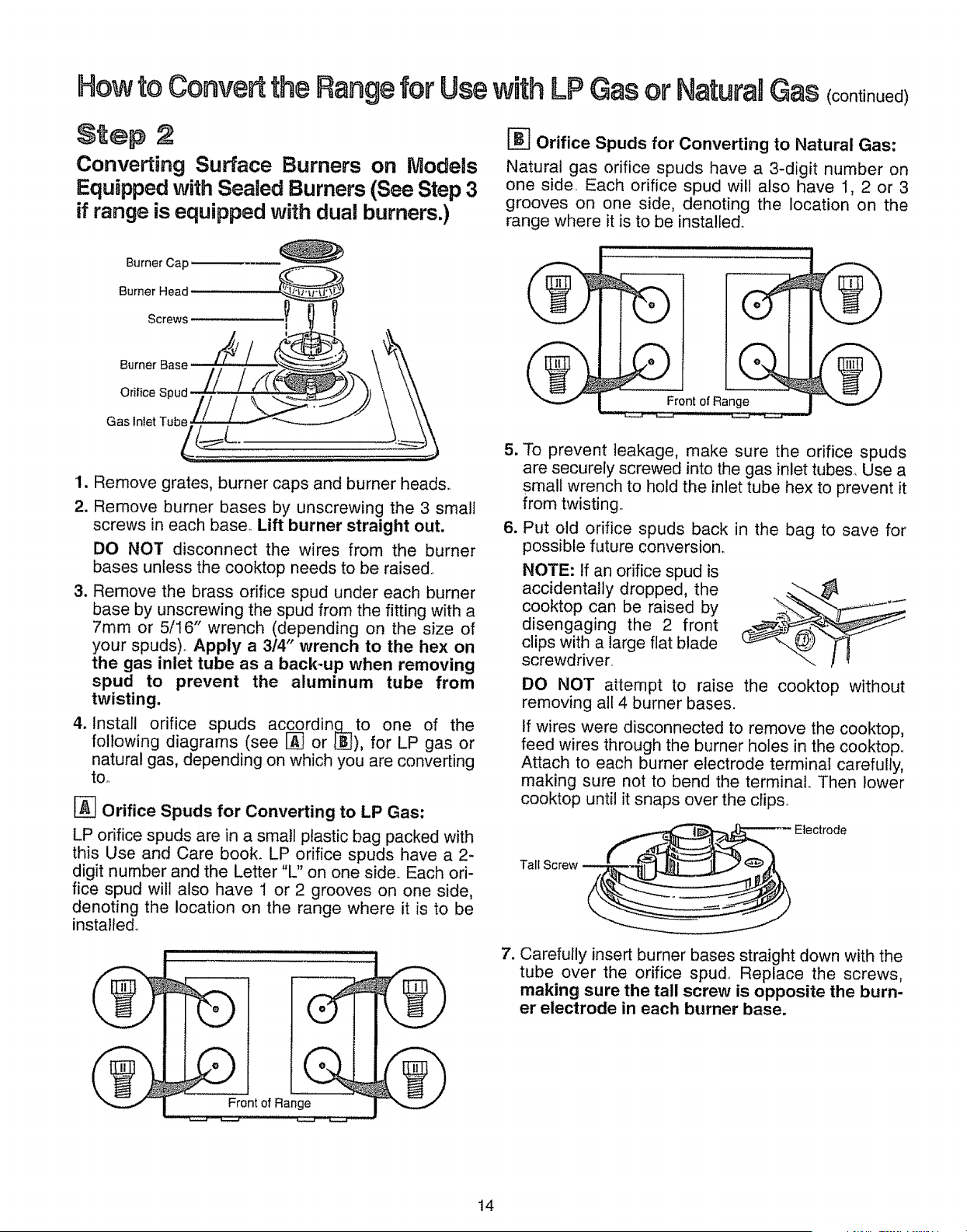
Step :2
Converting Surface Burners on Models
Equipped with Sealed Burners (See Step 3
if range is equipped with dual burners.)
Burner Cap
Burner Head
Screws
!
Burner Base
Orifice Spud
1. Remove grates, burner caps and burner heads.
2. Remove burner bases by unscrewing the 3 small
screws in each base. Lift burner straight out.
DO NOT disconnect the wires from the burner
bases unless the cooktop needs to be raised,
3. Remove the brass orifice spud under each burner
base by unscrewing the spud from the fitting with a
7mm or 5/16" wrench (depending on the size of
your spuds), Apply a 314" wrench to the hex on
the gas inlet tube as a back_up when removing
spud to prevent the aluminum tube from
twisting.
4. install orifice spuds acc__qording,to one of the
following diagrams (see _ or L_), for LP gas or
natural gas, depending on which you are converting
tOo
_-_ Orifice Spuds for Converting to LP Gas:
LP orifice spuds are in a small plastic bag packed with
this Use and Care book. LP orifice spuds have a 2-
digit number and the Letter "L" on one side° Each ori-
fice spud will also have I or 2 grooves on one side,
denoting the location on the range where it is to be
installed.
Orifice Spuds for Converting to Natural Gas:
Natural gas orifice spuds have a 3-digit number on
one side.. Each orifice spud will also have 1, 2 or 3
grooves on one side, denoting the location on the
range where it is to be installed.
m !
Front of Range
5_
6_
To prevent leakage, make sure the orifice spuds
are securely screwed into the gas inlet tubes_ Use a
small wrench to hold the inlet tube hex to prevent it
from twisting..
Put old orifice spuds back in the bag to save for
possible future conversion,.
NOTE: If an orifice spud is
accidentally dropped, the
cooktop can be raised by
disengaging the 2 front
clips with a large flat blade
screwdriver.
DO NOT attempt to raise the cooktop without
removing all 4 burner bases.
if wires were disconnected to remove the cooktop,
feed wires through the burner holes in the cooktop.
Attach to each burner electrode terminal carefully,
making sure not to bend the terminal. Then lower
cooktop until it snaps over the clips_
Tall Screw
| o I
Front of Range
7. Carefully insert burner bases straight down with the
tube over the orifice spud,. Replace the screws,
making sure the tall screw is opposite the burn-
er electrode in each burner base.
14
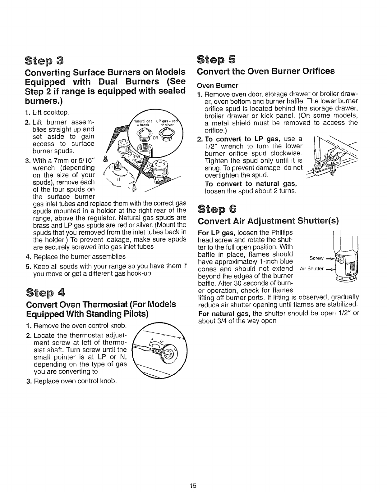
Step 3
Converting Surface Burners on Models
Equipped with Dual Burners (See
Step 2 if range is equipped with sealed
burners.)
1. Lift cooktop.,
2. Lift burner assem-
blies straight up and
set aside to gain
access to surface
burner spuds°
3. With a 7mm or 5/16"
wrench (depending
on the size of your
spuds), remove each
of the four spuds on
the surface burner
gas inlet tubes and replace them with the correct gas
spuds mounted in a holder at the right rear of the
range, above the regulator, Natural gas spuds are
brass and LP gas spuds are red or silver. (Mount the
spuds that you removed from the inlet tubes back in
the holder,) To prevent leakage, make sure spuds
are securely screwed into gas inlet tubes,
4. Replace the burner assemblies,
5. Keep all spuds with your range so you have them if
you move or get a different gas hook-up.
Step 4
Convert Oven Thermostat (For ModeDs
Equipped With Standing Pilots)
t. Remove the oven control knob.
2. Locate the thermostat adjust-
ment screw at left of thermo-
stat shaft., Turn screw until the
small pointer is at LP or N,
depending on the type of gas
you are converting to.
3. Replace oven control knob.
Step 5
Convert the Oven Burner Orifices
Oven Burner
1. Remove oven door, storage drawer or broiler draw-
er, oven bottom and burner baffle,. The lower burner
orifice spud is located behind the storage drawer,
broiler drawer or kick panel., (On some models,
a metal shield must be removed to access the
orifice.)
2. To convert to LP gas, use a i_.._'.-._ _
1/2" wrench to turn the lower
burner orifice spud clockwise,,
Tighten the spud only until it is
snug, To prevent damage, do not
overtighten the spud
To convert to natural gas,
loosen the spud about 2 turns.
Step 6
Convert Air Adjustment Shutter(s)
For LP gas, loosen the Phillips
head screw and rotate the shut-
ter to the full open position. With
baffle in place, flames should
have approximately 1-inch blue
cones and should not extend
beyond the edges of the burner
baffle, After 30 seconds of burn-
ScrewAir Shutter
er operation, check for flames
lifting off burner ports, If lifting is observed, gradually
reduce air shutter opening until flames are stabilized°
For natural gas, the shutter should be open 1t2" or
about 3/4 of the way open,
15
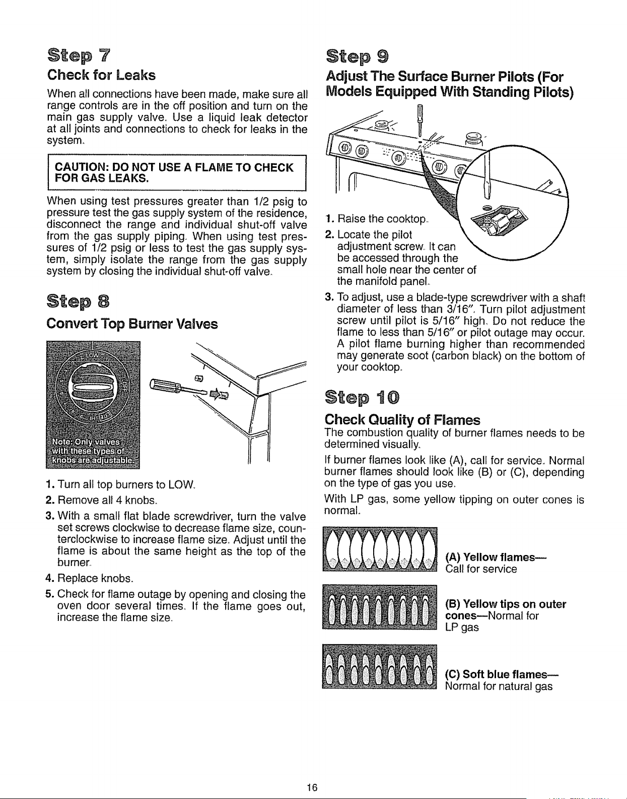
Step 7
Check for Leaks
When all connections have been made, make sure all
range controls are in the off position and turn on the
main gas supply valve. Use a liquid leak detector
at all joints and connections to check for leaks in the
system
I CAUTION: DO NOT USE A FLAME TO CHECK |
!
FOR GAS LEAKS.
l
When using test pressures greater than 1/2 psig to
pressure test the gas supply system of the residence,
disconnect the range and individual shut-off valve
from the gas supply piping. When using test pres-
sures of 1/2 psig or less to test the gas supply sys-
tem, simply isolate the range from the gas supply
system by closing the individual shut-off valve.
Step 8
Convert Top Burner Valves
1. Turn all top burners to LOW,,
2. Remove all 4 knobs.
3. With a small flat blade screwdriver, turn the valve
set screws clockwise to decrease flame size, coun-
terclockwise to increase flame size° Adjust until the
flame is about the same height as the top of the
burner.
4. Replace knobs.
5. Check for flame outage by opening and closing the
oven door several times, If the flame goes out,
increase the flame size,
$tep 9
Adjust The Surface Burner Pilots (For
Models Equipped With Standing Pilots)
1. Raise the cooktop.
2. Locate the pilot
adjustment screw.. It can
be accessed through the
small hole near the center of
the manifold panel°
3. To adjust, use a blade-type screwdriver with a shaft
diameter of less than 3/16"_ Turn pilot adjustment
screw until pilot is 5/16" high, Do not reduce the
flame to less than 5/16" or pilot outage may occur.
A pilot flame burning higher than recommended
may generate soot (carbon black) on the bottom of
your cooktop.
Step t @
Check Quality of Flames
The combustion quality of burner flames needs to be
determined visually,.
If burner flames look like (A), call for service., Normal
burner flames should look like (B) or (C), depending
on the type of gas you use.
With LP gas, some yellow tipping on outer cones is
normal.
(A) "fellow flames--
Call for service
(B) Yellow tips on outer
conesmNormal for
LP gas
(C) Soft blue flames--
Normal for natural gas
16
•:i ::::::!:,:::ii:_:_::iil¸:•::•::::•:::_!::i:::::::¸•:•!:::::¸:::•:i•: : •::: :!•:•: :: •i:i•:::•::i:: !•!: ::: ::::::: :••:::_:: ::••:::::••:!:: _ •:
BMPORTANT SAFETY :mNSTRUCTIONS ....
::
Read aUlinstructions before using this appliance.
i .... : i .... i
iMPORTANT SAFETY NOTnCE o Be sure all packing materials are removed
o The California Safe Drinking Water and
Toxic :Enforcement Act requires the
Governor of California to publish a list of sub-
stances known to the state to cause cancer,
birth defects or other reproductive harm, and
requires businesses to warn customers of
potential exposure to such substances.
Gas appliances cause minor exposure to
four of these substances, namely benzene,
carbon monoxide, formaldehyde and soot,
caused primarily by the incomplete combustion
of natural gas or LP fuels. Properly adjusted
burners, indicated by a bluish rather than a yel-
low flame, will minimize incomplete combus-
tion. Exposure to these substances can be
minimized further by venting with an open win-
dow or using a ventilation fan or hood.
o Fluorescent light bulbs and safety valves
on standing pilot ranges contain mercury.
If your model has these features, they must be
recycled according to local, state and federal
codes.
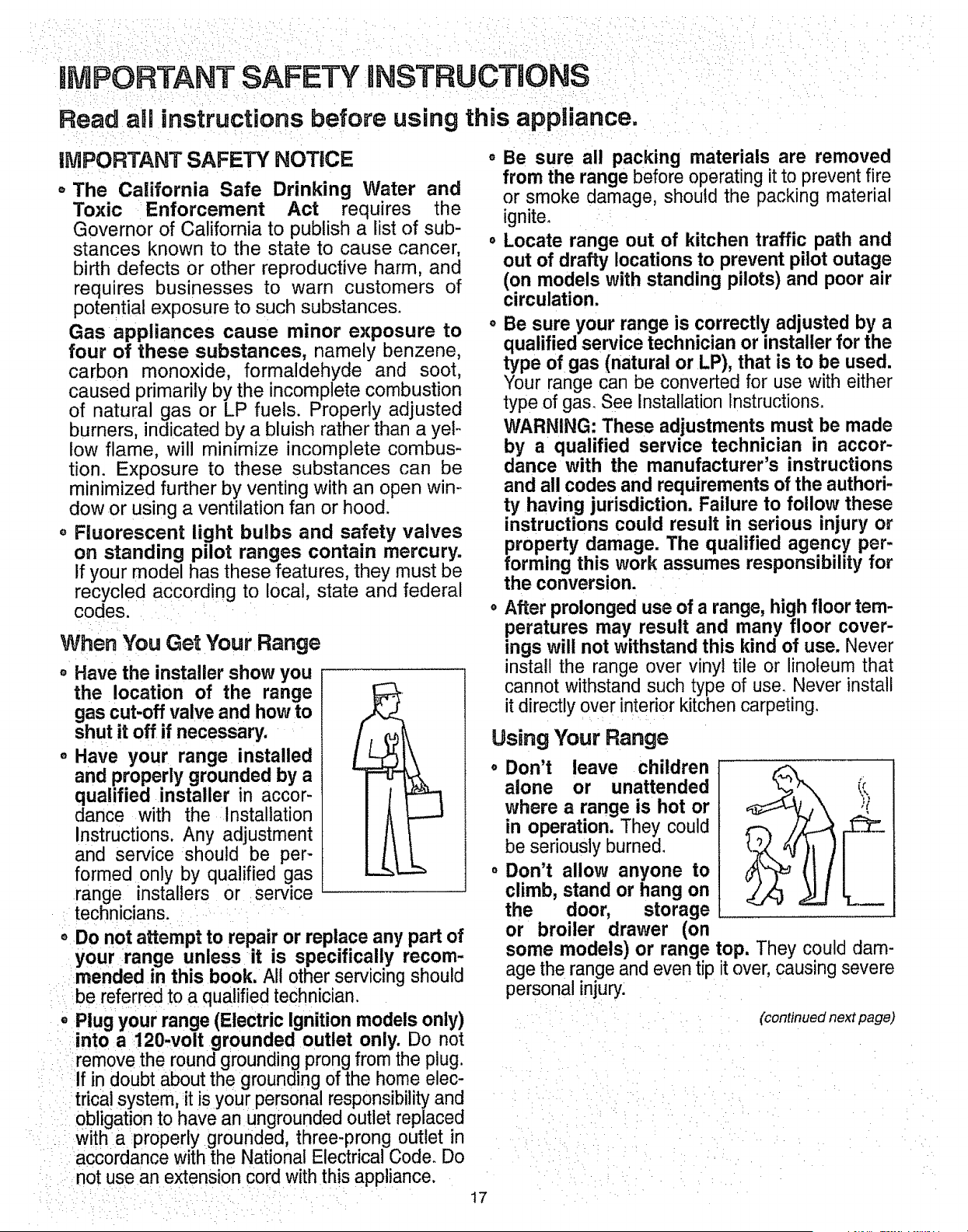
When You Get Your Range
o Have the installer show you
the location of the range
gas cut-off valve and how to
shut it off if necessary.
o Have your range installed
and properly grounded by a
qualified installer in accor-
dance with the Installation
Instructions. Any adjustment
and service should be per-
formed only by qualified gas
range installers or :service
technicians. ....
oDo not attempt to repair or replace any part of
your range unless it is specifically recom-
mended in this book, All other servicing should
be referred to a qualified technician.
0 Plug your range (Electric Ignition models only)
.... into:a 120-volt grounded outlet only. Do not
i ::remove the round grounding prong from the plug.
ilf in doubt about the grounding of the home elec-
i:i::trical system, it is your personal responsibility and
i i obligation to have an ungrounded outlet replaced
!: With a properly grounded, three-prong outlet in
:i'accordance with the National Electrical Code. Do
::::::::notuse an extension cord with this appliance.
from the range before operating it to prevent fire
or smoke damage, should the packing material
ignite.
o Locate range out of kitchen traffic path and
out of drafty locations to prevent pilot outage
(on models with standing pilots) and poor air
circulation.
o Be sure your range is correctly adjusted by a
qualified serv=ce techmcian or installer for the
type of gas (natural or LP), that is to be used.
Your range can be converted for use with either
type of gas. See Installation Instructions.
WARNING: These adjustments must be made
by a qualified service technician in accor-
dance with the manufacturer's instructions
and all codes and requirements of the authori-
ty having jurisdiction. Failure to follow these
instructions could result in serious injury or
property damage. The qualified agency per-
forming this work assumes responsibdity for
the conversion.
o After prolonged use of a range, high floor tem-
peratures may. result and many floor cover-
ings will not w|thstand this kind of use. Never
install the range over vinyl tile or linoleum that
cannot withstand such type of use. Never install
it directly over interiorkitchen carpeting.
Using Your Range
• Don't leave children
alone or unattended
where a range is hot or
in operation. They could
be seriously burned.
o Don't allow anyone to
climb, stand or hang on
the door, storage
or broiler drawer (on
some models) or range
age the range and even tip
personal injury:
• :: : ::ii :i::ii:: : :ii:i:::i_
17 •••
top. They could dam-
it over, causing severe
(continued next page)
MPORTANT SAFE INSTRUCTIONS (continued)
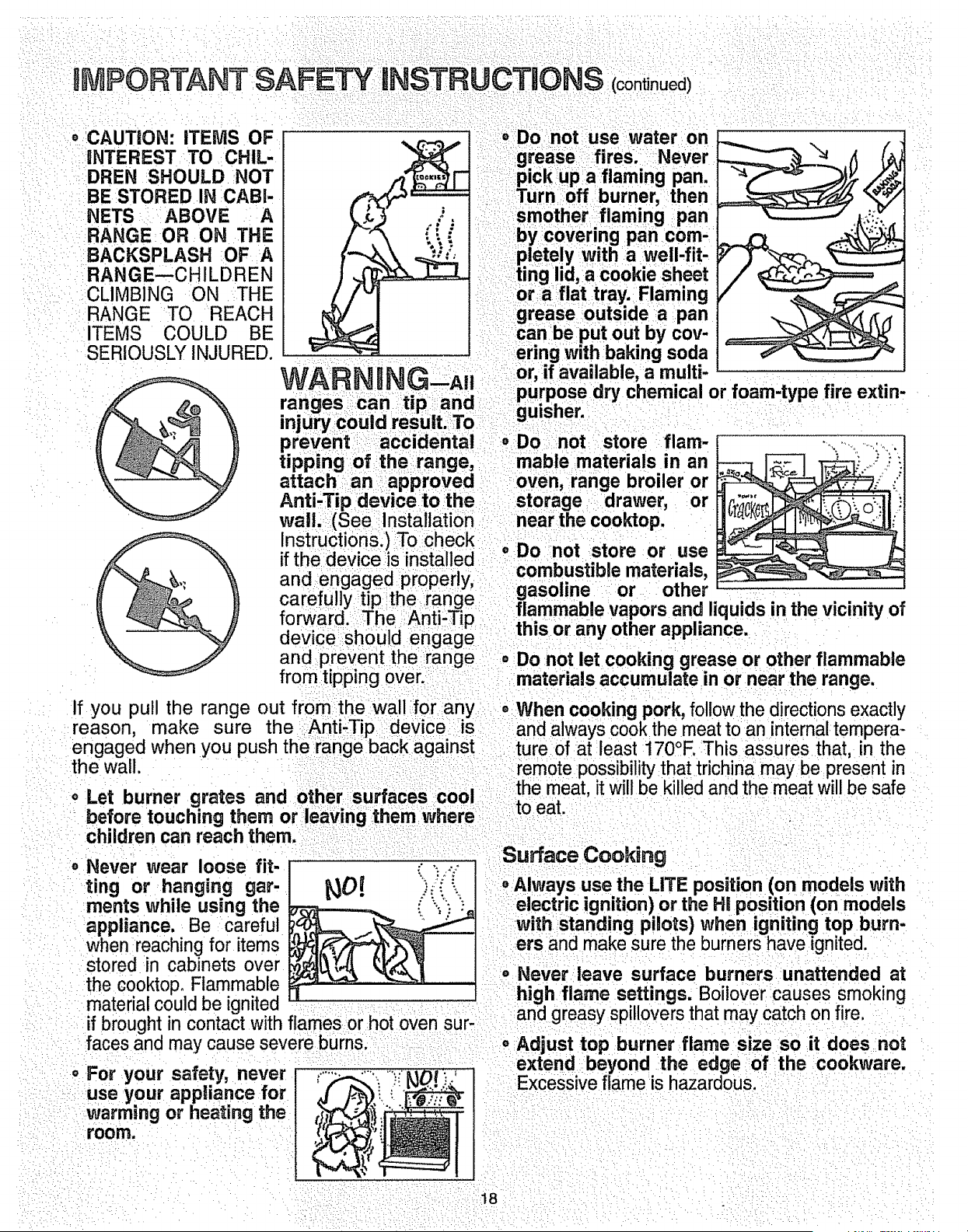
• CAUTION: iTEMS OF
INTEREST TO CHIL-
DREN SHOULD NOT
BE STORED IN CABi-
NETS ABOVE A
RANGE IOR ON THE
BACKSPLASH OF A
RANGE--CHILDREN
CLIMBING ON THE
RANGE TO REACH
ITEMS COULD BE
SERIOUSLY INJURED.
o_Do not use water on
grease :i_fires. Never
pick up a flaming pan,
Turnoff burner, then
smother flaming pan
by covering pan com-
pletely with a well-fit'
ting lid,la icookie sheet
or a flat tray.: Flaming
grease outside a pan
can be put out by cov-
ering with baking soda
or, if available, a multi-
purpose dry chemical or foam,type fire extin-
gu!sher.
oDo not store flare-
• ,o
• , ., _ %,k"
device should engage
and prevent the range = Do not let cooking grease or other flammable
from tipping over. materials accumulate in or near the range.
If you pull the range out from the wall for any • When cooking pork, follow the directions exactly
reason, make sure the Anti-Tip device is and always cook the meat to an internaltempera-
engaged when you push the range back against ture of at least 170°F. This assures that, in the
the wall. remote possibility that trichina may be present in
-'o-' the meat, it will be killed and the meat will be safe
o Let burner grates and other surfaces u uJ .....toeat.
before touching them or leaving them where
children can reach them.
Never wear loose fit- _ _-
ring or hanging gar- _0!
ments while using the
appliance. Be careful
when reachingfor items
stored in cabinets over
the cooktop. Flammable
material could be ignited
if brought in contact with flames or hot oven sur-
faces and may cause severe burns;
For your safety, never
use your appliance for
Warming or heating the
room.
Surface Cooking
• Always usethe LITE position (on models with
electric ign,tion! or the Ht position (on models
:w=th standing pdots) when =gnitmg top burn-
ers and make sure the burners have ignited.
° Never leave surface burners unattended at
high flame settings. Boilover causes smoking
and greasy spillovers that may catch on fire.
o Adjust top burner flame size so it does not
extend: beyond the edge of the cookware.
Excessiveflame is hazardous.
18

,(, i: _i_,_•
o Use only dry pot holders--moist or damp pot ° Never try to move a pan of hot fat, especially a
holders on hot surfaces may result in burns from deep fat fryer. Wait until the fat is coo!.
=steam. _ .... "
.... o Use proper pan size. Avoid pans that are unsta-
Do not let pot holders come near open flames
when lifting cookware. Do not use a towel or
other bulky cloth in place of a pot holder.
To minimize the possibility of burns, ignitionof
flammable materials and spillage, turn cookware
handles toward the side or back of the range with-
out letting them extend over adjacent burners.
Always turn surface burner to OFF before
removing cookware.
Carefully watch foods being fried at a high
flame setting.
Never block the vents (air openings) of the
range. They provide the air inlet and outlet that
are necessary for the range to operate properly
with correct combustion. Air openings are located
in the following places:
--Oven vent at the rear of the cooktop.
--Air intake under the broiler drawer.
--Air vent at the top of the oven door.
o Do not use a wok on models with sealed burn-
ers if the wok has a round metal ring that is
placed over the burner grate to support the
wok, This ring acts as a heat trap, which may
damage the burner grate and burner head. Also, it
may cause the burner to work improperly. This
may cause a carbon monoxide level above that
allowed by current standards, resulting in a health
hazard.
o Foods for frying should be as dry as possible.
Frost on frozen foods or moisture on fresh foods
can cause hot fat to bubble up and over sides of
pan.
Use least possible amount of fat for effective
shaRIowor deep-fat frying. Filling the pan too full
of fat can cause spillovers when food is added.
• If a combination of oils or fats will be used in
frying, stir together before heating or as fats melt
slowly.
o Always heat fat slowly and watch as it heat&
Use deep-fat thermometer whenever possible
to prevent overheating fat beyond the smoking
point.
ble or easily tipped. Select cookware having flat
bottoms large enough to properly contain food
and avoid boilovers and spilfovers and large
enough to cover burner grates. This will both save
cleaning time and prevent hazardous accumula-
tions of food, since heavy spattering or spillovers
left on the range can ignite. Use pans with han-
dles that can be easily grasped and will remain
coolo
When using glass cookware, make sure it is
designed for top-of-range cooking.
Keep all plastics away
from top burners.
Do not leave plastic
items on the cook-
top--they may melt if
left too close to the venL
Do not leave any items on the cooktop. The
hot air from the vent may ignite flammable items
and will increase pressure in closed containers,
which may cause them to burst.
o To avoid the possibility of a burn, always be
certain that the controls for all burners are at
the OFF position and all grates are cool before
attempting to remove them.
° When flaming foods are under the hood, turn
the fan off. The fan, if operating, may spread
the flames.
If range is located near a window, do not hang
long curtains that could blow over the top burners
and create a fire hazard.
When a pilot goes out (on models with stand-
ing pilots), you will detect a faint odor of gas as
your signal to relight the pilot. When relighting the
pilot, make sure the burner controls are in the
OFF position, and follow instructions in the
Installation Instructions to relight.
If you smell gas, and you have already made
sure the pilots are lit (on models with standing
pilots), turn off the gas to the range and call a
qualified service technician. Never use an open
flame to locate a leak.
(continued next page)
19
IMPORTANT SAFETY NSTRUCTJON$ (continued)
Baking, Broiging and Roasting Cleaning Your Range
oDo not use oven for a storage area. items o Clean only parts listed in this Use and Care
stored in the oven can ignite. Guide.
o Stand away from the range when opening the
door of a hot oven, The hot air and steam that
escape can cause burns to hands, face and
eyes:
oKeep oven free from grease buildup.
o Keep range clean and free of accumulations
of grease or spillovers, which may ignite.
o Be careful when you clean the cooktop
because the area over the pilot will be hot (for
standing pilot models).
Place oven shelves in desired position while
oven is cool.
Pulling out shelf to the shelf-stop is a
convenience in lifting heavy foods. It is also a
precaution against burns from touching hot
surfaces of the door or oven walls. The lowest
position "R" is not designed to slide.
Don't heat unopened food containers.
Pressure could build up and the container
could burst, causing an injury.
o For continuous clean models, do not use oven
cleaners on any of the continuous cleaning
surfaces. Continuous cleaning surfaces can be
identified by their rough surface finish.
SAVE THESE
nNSTRUCTBONS
o Don't use aluminum foil anywhere in the oven
except as described in this book. Misuse could
result in a fire hazard or damage to the ranger
o When using cooking or roasting bags in the
oven, follow the manufacturer's directions_
o Use onRyglass cookware that is recommend-
ed for use in gas ovens.
Always remove broiler pan from the broiler
compartment as soon as you finish broiling.
Grease left in the pan can catch on fire if oven is
used without removing the grease from the broiler
pan.
When broiling, if meat is too close to the
flame, the fat may ignite. Trim excess fat to pre-
vent excessive flare-ups.
Make sure broiter pan is in place correctly to
reduce the possibility of grease fires.
o If you should have a grease fire in the broiler
pan, turn off the OVEN CONTROL and keep
broiler compartment door closed to contain fire
until it burns out.
20
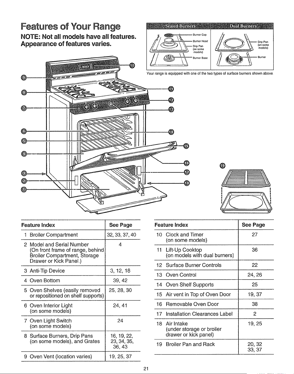
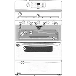
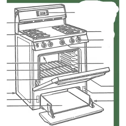
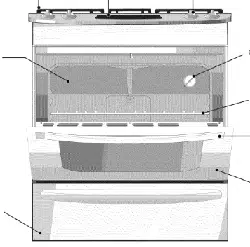
Features of Your Range
NOTE: Not amlmodels have all features.
Appearance of features varies.
@
Your range is equipped with one of lhe two types el surface burners shown above
@
@
@
@
@
! 1
\
®
@
@
®
! I
I I
Feature Index See Page
1 32, 33, 37, 40
2 4
3, 12, 18
39, 42
25, 28, 30
24, 41
24
16, !9, 22,
23, 34, 35,
36, 43
Broiler Compartment
Model and Serial Number
(On front frame of range, behind
Broiler Compartment, Storage
Drawer or Kick Panel,)
3 Anti-Tip Device
4 Oven Bottom
5 Oven Shelves (easily removed
or repositioned on shelf supports)
6 Oven Interior Light
(on some models)
7 Oven Light Switch
(on some models)
8 Surface Burners, Drip Pans
(on some models), and Grates
9 Oven Vent (location varies) t9, 25, 37
Feature Index See Page
10 Clock and Timer 27
(on some models)
11 Lift-Up Cooktop 36
(on models with dual burners)
12 Surface Burner Controls 22
13 Oven Control 24, 26
14 Oven Shelf Supports 25
15 Air vent in Top of Oven Door 19, 37
16 Removable Oven Door 38
17 Installation Clearances Label 2
18 Air Intake 19, 25
(under storage or broiler
drawer or kick panel)
19 Broiler Pan and Rack 20, 32
33, 37
21
Surface CeekJng
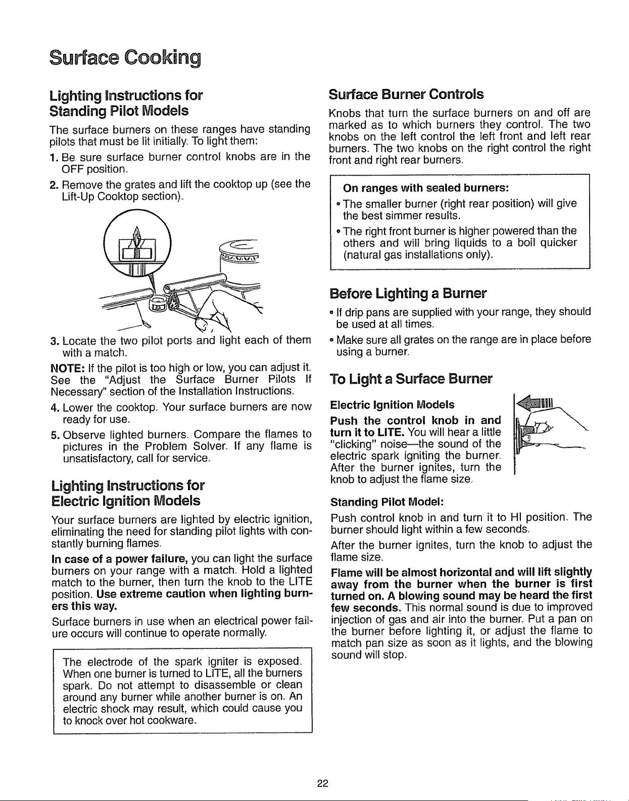
Lighting Instructions for
Standing Pilot Models
The surface burners on these ranges have standing
pilots that must be lit initially,. To light them:
1. Be sure surface burner control knobs are in the
OFF position_
2. Remove the grates and lift the cooktop up (see the
Lift-Up Cooktop section)..
Surface Burner Controls
Knobs that turn the surface burners on and off are
marked as to which burners they control,. The two
knobs on the left control the left front and left rear
burners. The two knobs on the right control the right
front and right rear burners.
On ranges with sealed burners:
o The smaller burner (right rear position) will give
the best simmer results.
o The right front burner is higher powered than the
others and wilt bring liquids to a boil quicker
(natural gas installations only).
3. Locate the two pilot ports and light each of them
with a match,.
NOTE: if the pilot is too high or tow, you can adjust iL
See the "Adjust the Surface Burner Pilots tf
Necessary" section of the Installation Instructions,.
4. Lower the cooktop. Your surface burners are now
ready for use,.
5. Observe lighted burners, Compare the flames to
pictures in the Problem Solver. If any flame is
unsatisfactory, call for sen/ice._
Lighting instructions for
Electric Ignition Models
Your surface burners are lighted by electric ignition,
eliminating the need for standing pilot lights with con-
stantly burning flames.
In case of a power failure, you can light the surface
burners on your range with a match. Hold a lighted
match to the burner, then turn the knob to the LITE
position. Use extreme caution when lighting burn-
ers this way.
Surface burners in use when an electrical power fail-
ure occurs will continue to operate normally,
The electrode of the spark igniter is exposed..
When one burner is turned to LITE, all the burners
spark° Do not attempt to disassemble or clean
around any burner while another burner is ono An
electric shock may result, which could cause you
to knock over hot cookware.
Before Lighting a Burner
o If drip pans are supplied with your range, they should
be used at all times.
° Make sure all grates on the range are in place before
using a burner.
To Light a Surface Burner
Electric ignition Models
Push the control knob in and
turn it to LITE. You will hear a little
"clicking" noise--the sound of the
electric spark igniting the burner..
After the burner ignites, turn the
knob to adjust the flame size,
Standing Pilot Model:
Push control knob in and turn it to H1 position. The
burner should light within a few seconds.
After the burner ignites, turn the knob to adjust the
flame size_
Flame will be almost horizontal and will lift slightly
away from the burner when the burner is first
turned on, A blowing sound may be heard the first
few seconds. This normal sound is due to improved
injection of gas and air into the burner. Put a pan on
the burner before lighting it, or adjust the flame to
match pan size as soon as it lights, and the blowing
sound will stop.
22
After Lighting a Burner
o Check to be sure the burner you turned on is the one
you want to user
o Do not operate a burner for an extended period of
time without cookware on the grate° The finish on the
grate may chip without cookware to absorb the heat.
o Be sure the burners and grates are cool before you
place your hand, a pot holder, cleaning cloths or
other materials on them.
How to Select Flame Size
Watch the flame, not the knob, as you reduce heat.
The flame size on a gas burner should match the
cookware you are using. ,_
FOR SAFE HANDLING OF ....::::_..............
COOKWARE NEVER LET
THE FLAME EXTEND LJP
THE SIDES OF THE COOK-
WARE. Any flame larger than the bottom of the cook-
ware is wasted and only serves to heat the handle.
Top-of-Range Cookware
Aluminum: Medium-weight cookware is recommend-
ed because it heats quickly and evenly° Most foods
brown evenly in an aluminum skillet° Use saucepans
with tight-fitting lids when cooking with minimum
amounts of water.
Cast-Iron: If heated slowly, most skillets will give sat-
isfactory results.
Enamelware: Under some conditions, the enamel of
some cookware may melt. Follow cookware manufac-
turer's recommendations for cooking methods.
Glass: There are two types of glass cookware--those
for oven use only and those for top-of-range cooking
(saucepans, coffee and teapots). Glass conducts heat
very slowly°
Heatproof Glass Ceramic: Can be used for either
surface or oven cooking., tt conducts heat very slowly
and cools very slowly_ Check cookware manufactur-
er's directions to be sure it can be used on gas range&
Stainless Steel: This metal alone has poor heating
properties and is usually combined with copper, alu-
minum or other metals for improved heat distribution,.
Combination metal skillets usually work satisfactorily if
they are used with medium heat as the manufacturer
recommends°
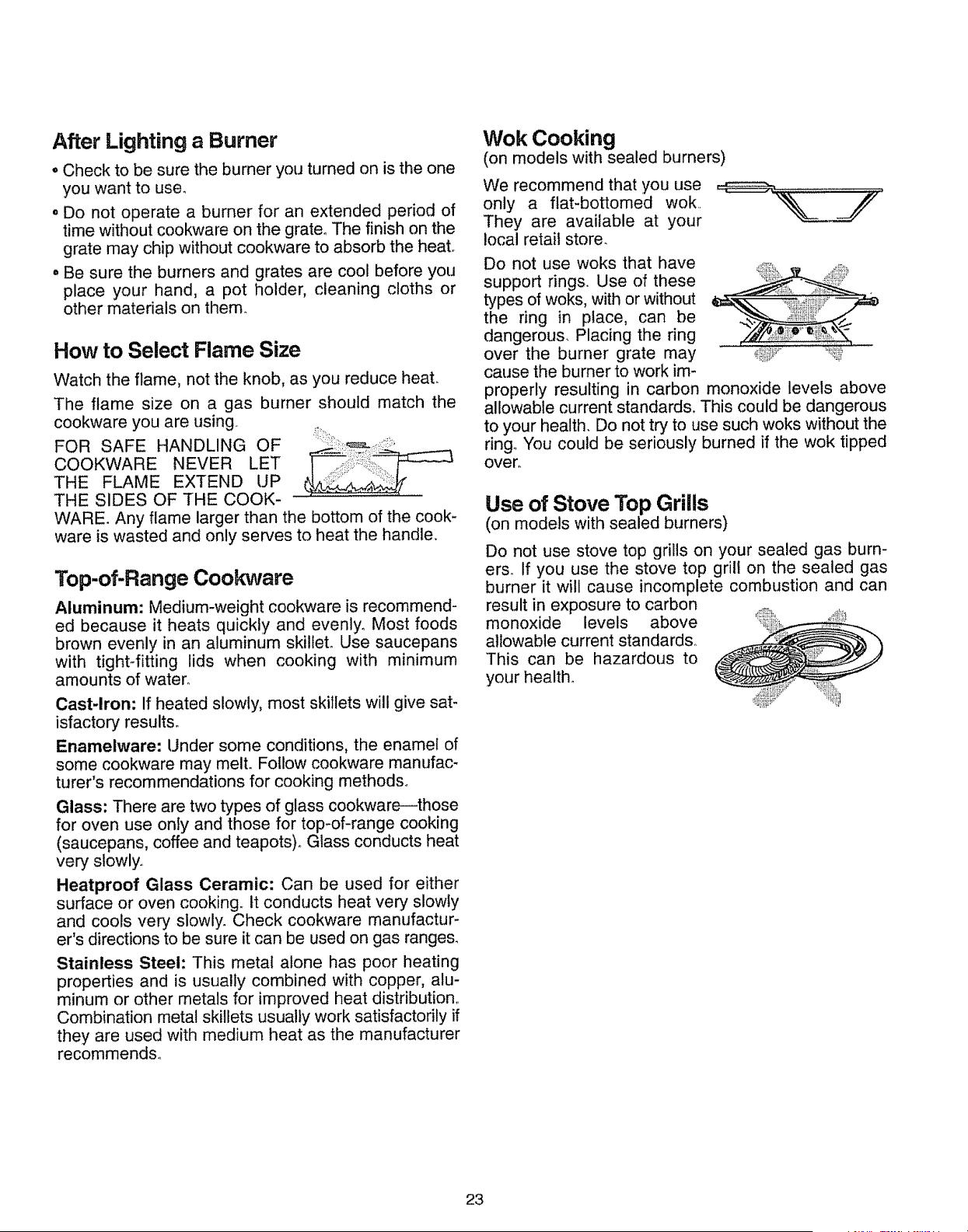
Wok Cooking
(on models with sealed burners)
We recommend that you use
only a flat-bottomed wok..
They are available at your
local retail store.
Do not use woks that have .....
support ring&. Use of these
types of woks, with or without
the ring in place, can be
dangerous. Placing the ring
over the burner grate may ,_i,:__.................................._ii'....
cause the burner to work im-
properly resulting in carbon monoxide levels above
allowable current standards. This could be dangerous
to your health. Do not try to use such woks without the
ring. You could be seriously burned if the wok tipped
over_
Use of Stove Top Grills
(on models with sealed burners)
Do not use stove top grills on your sealed gas burn-
ers. If you use the stove top grill on the sealed gas
burner it will cause incomplete combustion and can
result in exposure to carbon
monoxide levels above
allowable current standard&
This can be hazardous to
your health°
23
Using Your Oven
Before Using Your Oven
Be sure you understand how to set the control proper-
ly., Practice removing and replacing the shelves while
the oven is cool_ Read the information and tips on the
following pages_ Keep this book handy where you can
refer to it, especially during the first weeks of using
your new range°
Lighting Instructions for
Standing Pilot Models
Some models have standing oven pilots that must be
lit initially°
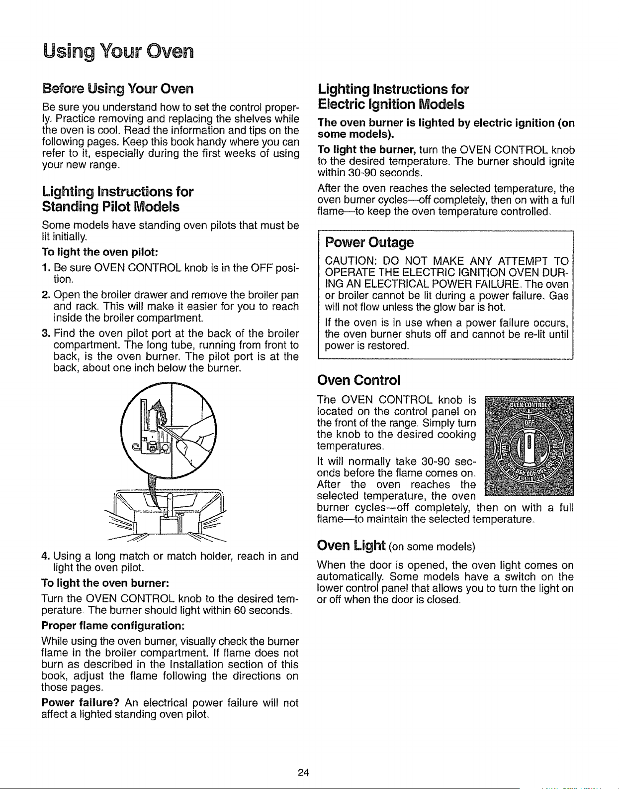
To light the oven pilot:
1. Be sure OVEN CONTROL knob is in the OFF posi-
tion.
2. Open the broiler drawer and remove the broiler pan
and rack_ This will make it easier for you to reach
inside the broiler compartment,.
3. Find the oven pilot port at the back of the broiler
compartment,, The long tube, running from front to
back, is the oven burner. The pilot port is at the
back, about one inch below the burner°
4. Using a long match or match holder, reach in and
light the oven piloL
To light the oven burner:
Turn the OVEN CONTROL knob to the desired tem-
perature. The burner should light within 60 seconds_
Proper flame configuration:
While using the oven burner, visually check the burner
flame in the broiler compartment,, If flame does not
burn as described in the Installation section of this
book, adjust the flame following the directions on
those pages°
Power failure? An electrical power failure will not
affect a lighted standing oven pilot.
Lighting instructions for
Electric ignition iVlodels
The oven burner is lighted by electric ignition (on
some models).
To light the burner, turn the OVEN CONTROL knob
to the desired temperature_ The burner should ignite
within 30-90 seconds.
After the oven reaches the selected temperature, the
oven burner cycles--off completely, then on with a full
flame--to keep the oven temperature controlled,
Power Outage
CAUTION: DO NOT MAKE ANY ATTEMPT TO
OPERATE THE ELECTRIC IGNITION OVEN DUR-
ING AN ELECTRICAL POWER FAILURE, The oven
or broiler cannot be lit during a power failure. Gas
will not flow unless the glow bar is hot.
If the oven is in use when a power failure occurs,
the oven burner shuts off and cannot be re-lit until
power is restored,,
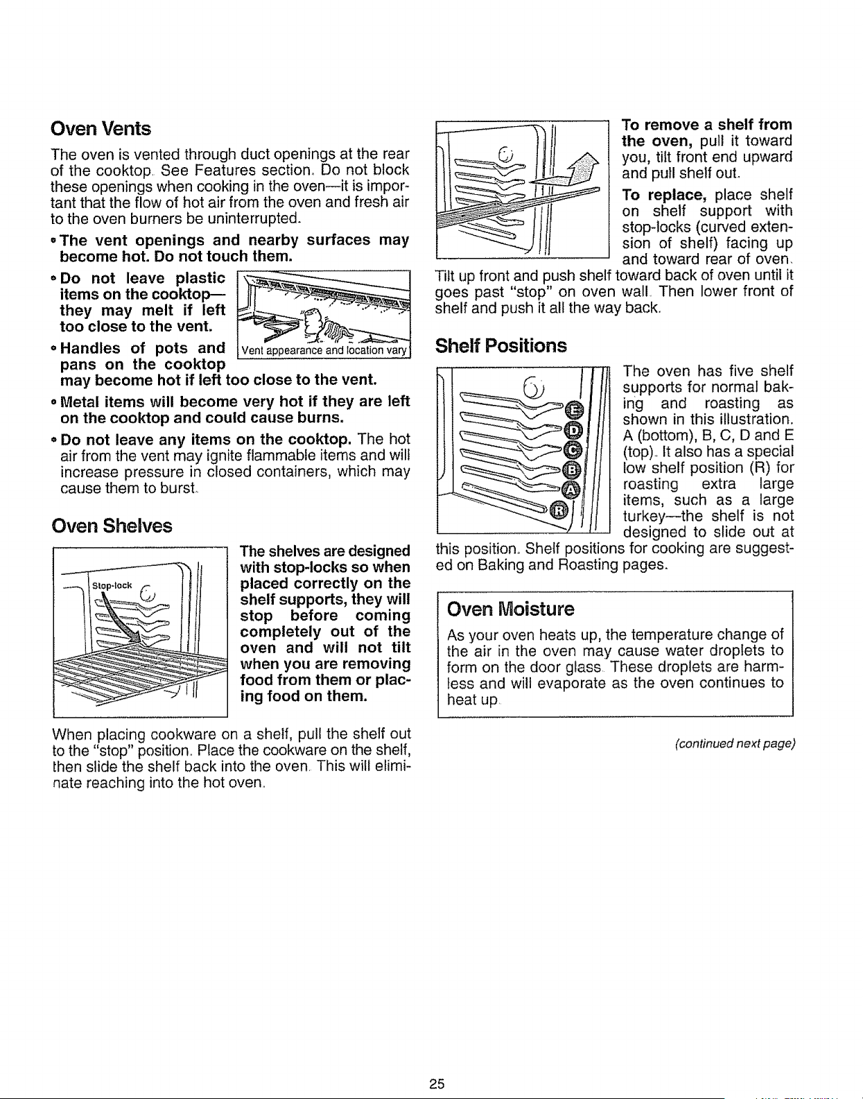
Oven Control
The OVEN CONTROL knob is
located on the control panel on
the front of the range, Simply turn
the knob to the desired cooking
temperatures
it will normally take 30-90 sec-
onds before the flame comes on,,
After the oven reaches the
selected temperature, the oven
burner cycles--off completely, then on with a full
flame--to maintain the selected temperature_
Oven Light (on some models)
When the door is opened, the oven light comes on
automatically° Some models have a switch on the
lower control panel that allows you to turn the light on
or off when the door is closed,
24
Oven Vents
The oven is vented through duct openings at the rear
of the cooktop See Features section. Do not block
these openings when cooking in the oven--it is impor-
tant that the flow of hot air from the oven and fresh air
to the oven burners be uninterrupted.
,The vent openings and nearby surfaces may
become hot. Do not touch them.
o Do not leave plastic
items on the cooktop---
they may melt if left
too close to the vent.
• Handles of pots and
pans on the cooktop
may become hot if left too close to the vent.
o Metal items will become very hot if they are left
on the cool{top and could cause burns,
o Do not leave any items on the cooktop. The hot
air from the vent may ignite flammable items and will
increase pressure in closed containers, which may
cause them to burst.
Oven Shelves
The shelves are designed
with stop-locks so when
placed correctly on the
shelf supports, they will
stop before coming
completely out of the
oven and will not tilt
when you are removing
food from them or plac-
ing food on them.
When placing cookware on a shelf, pull the shelf out
to the "stop" position.. Place the cookware on the shelf,
then slide the shelf back into the oven. This will elimi-
nate reaching into the hot oven..
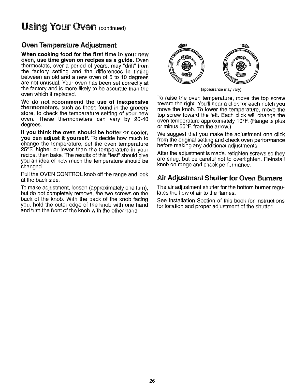
To remove a shelf from
the oven, pull it toward
you, tilt front end upward
and pull shelf out°
To replace, place shelf
] on shelf support with
stop-locks (curved exten-
sion of shelf) facing up
and toward rear of oven.
Tilt up front and push shelf toward back of oven until it
goes past "stop" on oven wall. Then lower front of
shelf and push it all the way back..
Shelf Positions
The oven has five shelf
supports for normal bak-
ing and roasting as
shown in this illustration,
A (bottom), B, C, D and E
(top). It also has a special
low shelf position (R) for
roasting extra large
items, such as a large
turkey--the shelf is not
designed to slide out at
this position.. Shelf positions for cooking are suggest-
ed on Baking and Roasting pages.
Oven Moisture
As your oven heats up, the temperature change of
the air in the oven may cause water droplets to
form on the door glass These droplets are harm-
less and will evaporate as the oven continues to
heat up
(continued next page)
25
USing VOu_' Oven (continued)
Oven Temperature Adjustment
When cooking food for the first time in your new
oven, use time given on recipes as a guide. Oven
thermostats, over a period of years, may "drift" from
the factory setting and the differences in timing
between an old and a new oven of 5 to 10 degrees
are not unusual. Your oven has been set correctly at
the factory and is more likely to be accurate than the
oven which it replaced.
We do not recommend the use of inexpensive
thermometers, such as those found in the grocery
store, to check the temperature setting of your new
oven. These thermometers can vary by 20-40
degree&
If you think the oven should be hotter or cooler,
you can adjust it yourself. To decide how much to
change the temperature, set the oven temperature
25°E higher or lower than the temperature in your
recipe, then bake. The results of this "test" should give
you an idea of how much the temperature should be
changed..
Pull the OVEN CONTROL knob off the range and look
at the back side.
To make adjustment, loosen (approximately one turn),
but do not completely remove, the two screws on the
back of the knob. With the back of the knob facing
you, hold the outer edge of the knob with one hand
and turn the front of the knob with the other hand.
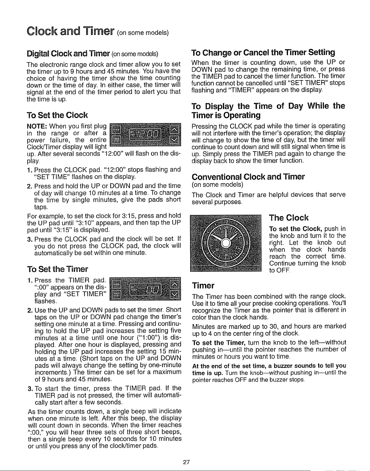
(appearance may vary)
To raise the oven temperature, move the top screw
toward the right. You'll hear a click for each notch you
move the knob. To lower the temperature, move the
top screw toward the left. Each click will change the
oven temperature approximately 10°E, (Range is plus
or minus 60°E from the arrow°)
We suggest that you make the adjustment one click
from the original setting and check oven performance
before making any additional adjustments°
After the adjustment is made, retighten screws so they
are snug, but be careful not to overtighten. Reinstall
knob on range and check performance.
Air Adjustment Shutter for Oven Burners
The air adjustment shutter for the bottom burner regu-
lates the flow of air to the flames.
See installation Section of this book for instructions
for location and proper adjustment of the shutter.
26
Clock and Timer (onsome models)
DigF_aiClock and Timer (onsomemodels)
The electronic range clock and timer allow you to set
the timer up to 9 hours and 45 minutes You have the
choice of having the timer show the time counting
down or the time of day° In either case, the timer will
signal at the end of the timer period to alert you that
the time is up
To Set the Clock
NOTE: When you first plug
in the range or after a
power failure, the entire
Clock/Timer display will light
up. After several seconds "12:00" will flash on the dis-
play
1. Press the CLOCK pad, "12:00" stops flashing and
"SET TIME" flashes on the display.
2. Press and hold the UP or DOWN pad and the time
of day will change 10 minutes at a timer To change
the time by single minutes, give the pads short
taps.
For example, to set the clock for 3:15, press and hold
the UP pad until "3:10" appears, and then tap the UP
pad until "3:15" is displayed.
3. Press the CLOCK pad and the clock will be set if
you do not press the CLOCK pad, the clock will
automatically be set within one minute.
To Set the Timer
1. Press the TIMER pad_
":00" appears on the dis-
play and "SET TIMER"
flashes.
2. Use the UP and DOWN pads to set the timer Short
taps on the UP or DOWN pad change the timer's
setting one minute at a time. Pressing and continu-
ing to hold the UP pad increases the setting five
minutes at a time until one hour ("1:00") is dis-
played After one hour is displayed, pressing and
holding the UP pad increases the setting 15 min-
utes at a time. (Short taps on the UP and DOWN
pads will always change the setting by one-minute
increments.) The timer can be set for a maximum
of 9 hours and 45 minutes.
3. To start the timer, press the TIMER pad. If the
TIMER pad is not pressed, the timer will automati-
cally start after a few seconds°
As the timer counts down, a single beep will indicate
when one minute is lefto After this beep, the display
will count down in seconds_ When the timer reaches
":00," you will hear three sets of three short beeps,
then a single beep every 10 seconds for 10 minutes
or until you press any of the clockJtimer pads
To Change or Cancel the Timer Setting
When the timer is counting down, use the UP or
DOWN pad to change the remaining time, or press
the TIMER pad to cancel the timer function. The timer
function cannot be cancelled until "SET TIMER" stops
flashing and "TIMER" appears on the display.
To Display the Time of Day While the
Timer is Operating
Pressing the CLOCK pad while the timer is operating
will not interfere with the timer's operation; the display
will change to show the time of day, but the timer will
continue to count down and will still signal when time is
up. Simply press the TIMER pad again to change the
display back to show the timer function,
Conventional Clock and Timer
(on some models)
The Clock and Timer are helpful devices that serve
several purposes.
The Clock
To set the Clock, push in
the knob and turn it to the
right. Let the knob out
when the clock hands
reach the correct timer
Continue turning the knob
to OFE
Timer
The Timer has been combined with the range clock.
Use it to time all your precise cooking operations You'll
recognize the Timer as the pointer that is different in
color than the clock hands.
Minutes are marked up to 30, and hours are marked
up to 4 on the center ring of the clock_
To set the Timer, turn the knob to the left--without
pushing in--until the pointer reaches the number of
minutes or hours you want to time
At the end of the set time, a buzzer sounds to tell you
time is up. Turn the knob--without pushing in--until the
pointer reaches OFF and the buzzer stops_
27
Baking
How to Set Your Range for Baking
1. To avoid possible burns, place the shelves in the
correct position before you turn the oven on.
2. Close the oven door. Turn OVEN CONTROL knob
to desired temperature
3o Check food for doneness at minimum time on
recipe. Cook longer if necessary,. Turn OVEN
CONTROL knob to OFF and remove food..
For best baking results, follow these suggestions:
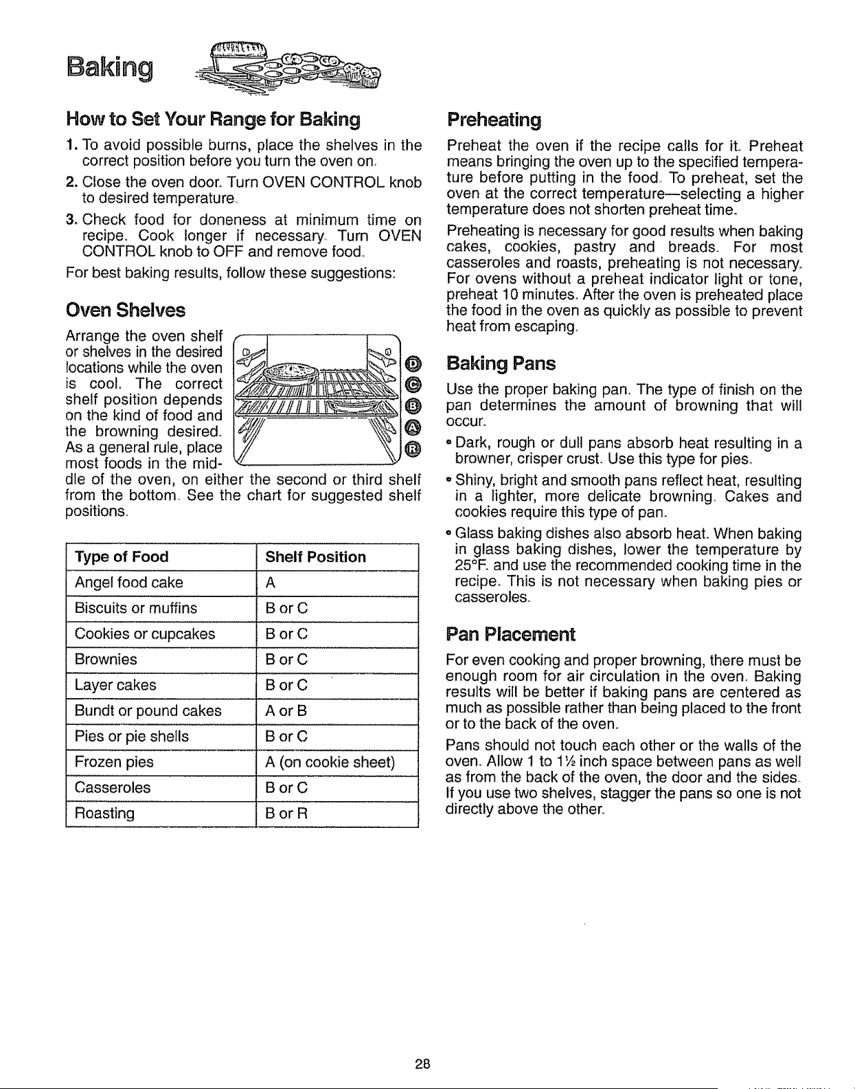
Oven Shelves
Arrange the oven shelf
or shelves in the desired
locations while the oven O
is cool_ The correct
shelf position depends _)
on the kind of food and _
the browning desired° O
As a general rule, place _)
most foods in the mid-
die of the oven, on either the second or third shelf
from the bottom. See the chart for suggested shelf
positions,.
Type of Food
Angel food cake A
Biscuits or muffins B or C
Cookies Or cupcakes g or C
Brownies B or C
Layer cakes B or C
Bundt or pound cakes A or B
Pies or pie shells B or C
............................... 1
Frozen pies A (on cookie sheet)
Casseroles B or C
....Roasting B or R .......
Shelf Position
Preheating
Preheat the oven if the recipe calls for it. Preheat
means bringing the oven up to the specified tempera-
ture before putting in the food To preheat, set the
oven at the correct temperature--selecting a higher
temperature does not shorten preheat time_
Preheating is necessary for good results when baking
cakes, cookies, pastry and breads° For most
casseroles and roasts, preheating is not necessary°
For ovens without a preheat indicator light or tone,
preheat 10 minutes. After the oven is preheated place
the food in the oven as quickly as possible to prevent
heat from escaping
Baking Pans
Use the proper baking pan_ The type of finish on the
pan determines the amount of browning that will
occur.,
o Dark, rough or dul! pans absorb heat resulting in a
browner, crisper crust. Use this type for pies_
° Shiny, bright and smooth pans reflect heat, resulting
in a lighter, more delicate browning. Cakes and
cookies require this type of pan.
o Glass baking dishes also absorb heat,. When baking
in glass baking dishes, lower the temperature by
25°F. and use the recommended cooking time in the
recipe_ This is not necessary when baking pies or
casseroles.,
Pan Placement
For even cooking and proper browning, there must be
enough room for air circulation in the oven,. Baking
results will be better if baking pans are centered as
much as possible rather than being placed to the front
or to the back of the oven.
Pans should not touch each other or the walls of the
oven. Allow I to 1_½inch space between pans as well
as from the back of the oven, the door and the sides_
If you use two shelves, stagger the pans so one is not
directly above the other°
28
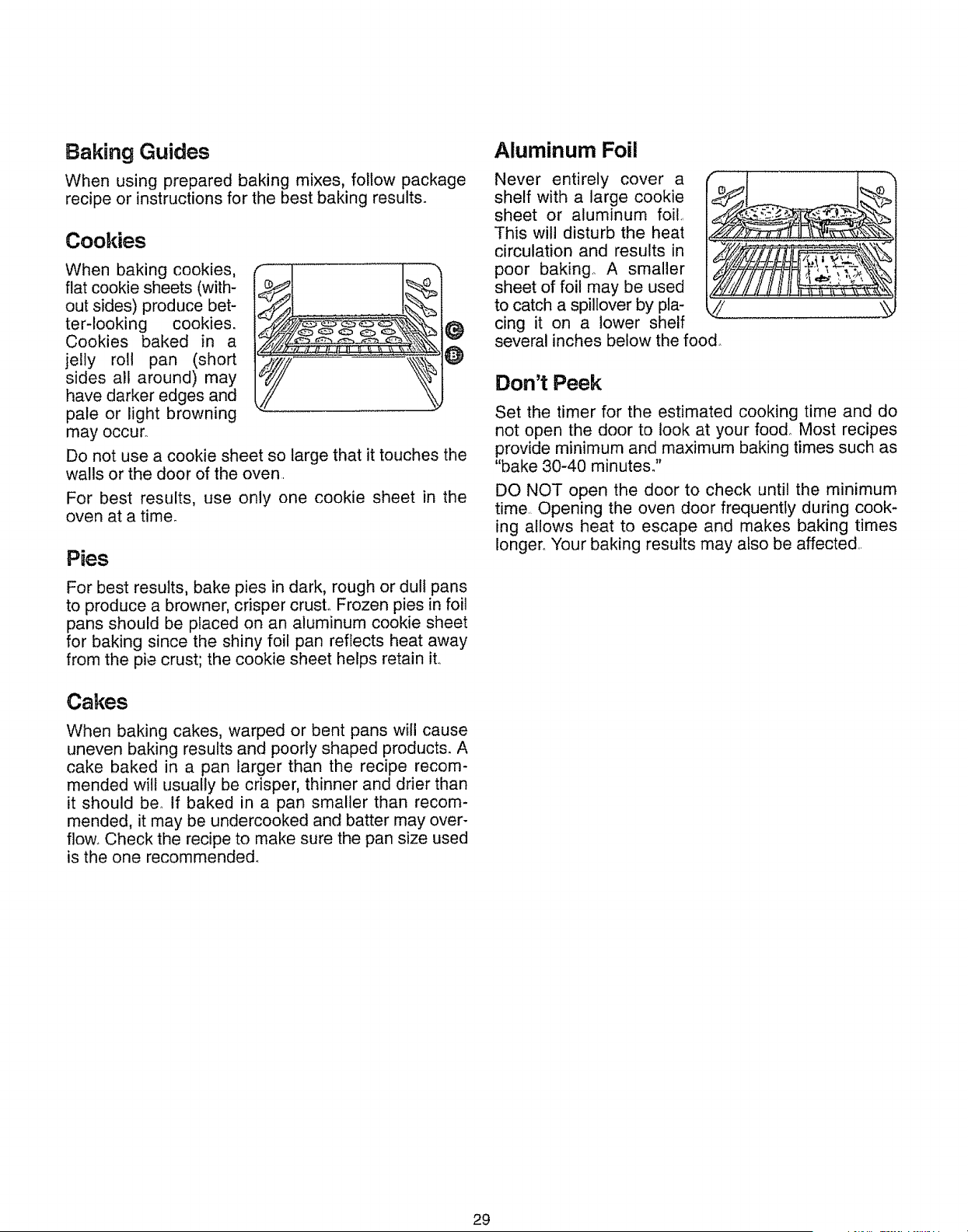
Baking Guides
When using prepared baking mixes, follow package
recipe or instructions for the best baking results°
Cookies
When baking cookies,
flat cookie sheets (with-
out sides) produce bet-
ter-looking cookies.
Cookies baked in a
jelly roll pan (short
sides all around) may
have darker edges and
pale or light browning
may occur.
Do not use a cookie sheet so large that it touches the
walls or the door of the oven.
For best results, use only one cookie sheet in the
oven at a time.
Pies
For best results, bake pies in dark, rough or dull pans
to produce a browner, crisper crust. Frozen pies in foil
pans should be placed on an aluminum cookie sheet
for baking since the shiny foil pan reflects heat away
from the pie crust; the cookie sheet helps retain it..
Cakes
When baking cakes, warped or bent pans will cause
uneven baking results and poorly shaped products. A
cake baked in a pan larger than the recipe recom-
mended will usually be crisper, thinner and drier than
it should beo If baked in a pan smaller than recom-
mended, it may be undercooked and batter may over-
flowo Check the recipe to make sure the pan size used
is the one recommended°
Aluminum Foil
Never entirely cover a
shelf with a large cookie
sheet or aluminum foil,
This will disturb the heat
circulation and results in
poor baking,, A smaller
sheet of foil may be used
to catch a spiltover by pla- _///
cing it on a lower shelf
several inches below the food.
Don't Peek
Set the timer for the estimated cooking time and do
not open the door to look at your food. Most recipes
provide minimum and maximum baking times such as
"bake 30-40 minutes."
DO NOT open the door to check until the minimum
time.. Opening the oven door frequently during cook-
ing allows heat to escape and makes baking times
longer.. Your baking results may also be affected..
29
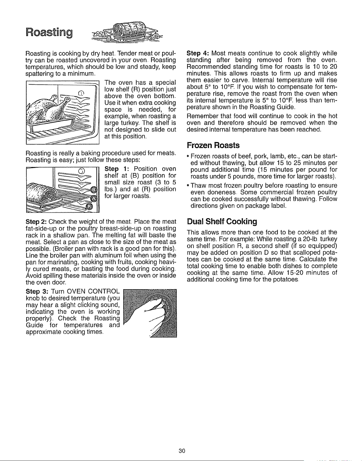
Roasting
Roasting is cooking by dry heat.. Tender meat or pou!-
try can be roasted uncovered in your oven Roasting
temperatures, which should be low and steady, keep
spattering to a minimum.
The oven has a special
low shelf (R) position just
above the oven bottom.
Use it when extra cooking
space is needed, for
example, when roasting a
large turkey., The shelf is
not designed to slide out
at this position..
Roasting is really a baking procedure used for meats.
Roasting is easy; just follow these steps:
_)_--}-_ Step 1: Position oven
shelf at (B) position forsmall size roast (3 to 5
lbs.) and at (R) position
for larger roasts..
Step 2: Check the weight of the meat. Place the meat
fat-side-up or the poultry breast-side-up on roasting
rack in a shallow pan,. The melting fat will baste the
meal Select a pan as close to the size of the meat as
possible. (Broiler pan with rack is a good pan for this).
Line the broiler pan with aluminum foil when using the
pan for marinating, cooking with fruits, cooking heavi-
ly cured meats, or basting the food during cooking.
Avoid spilling these materials inside the oven or inside
the oven door°
Step 3: Turn OVEN CONTROL
knob to desired temperature (you
may hear a slight clicking sound,
indicating the oven is working
properly).. Check the Roasting
Guide for temperatures and
approximate cooking times.
Step 4: Most meats continue to cook slightly while
standing after being removed from the oven.
Recommended standing time for roasts is 10 to 20
minutes,. This allows roasts to firm up and makes
them easier to carve° Internal temperature will rise
about 5° to 10°E If you wish to compensate for tem-
perature rise, remove the roast from the oven when
its internal temperature is 5 ° to 10°E tess than tem-
perature shown in the Roasting Guide,.
Remember that food will continue to cook in the hot
oven and therefore should be removed when the
desired internal temperature has been reached.
Frozen Roasts
• Frozen roasts of beef, pork, lamb, etc_, can be start-
ed without thawing, but allow 15 to 25 minutes per
pound additional time (15 minutes per pound for
roasts under 5 pounds, more time for larger roasts),.
. Thaw most frozen poultry before roasting to ensure
even doneness Some commercial frozen poultry
can be cooked successfully without thawing_ Follow
directions given on package label,.
Dual Shelf Cooking
This allows more than one food to be cooked at the
same time. For example: While roasting a 20-1b. turkey
on shelf position R, a second shelf (if so equipped)
may be added on position D so that scalloped pota-
toes can be cooked at the same timer Calculate the
total cooking time to enable both dishes to complete
cooking at the same time. Allow 15-20 minutes of
additional cooking time for the potatoes,
3O
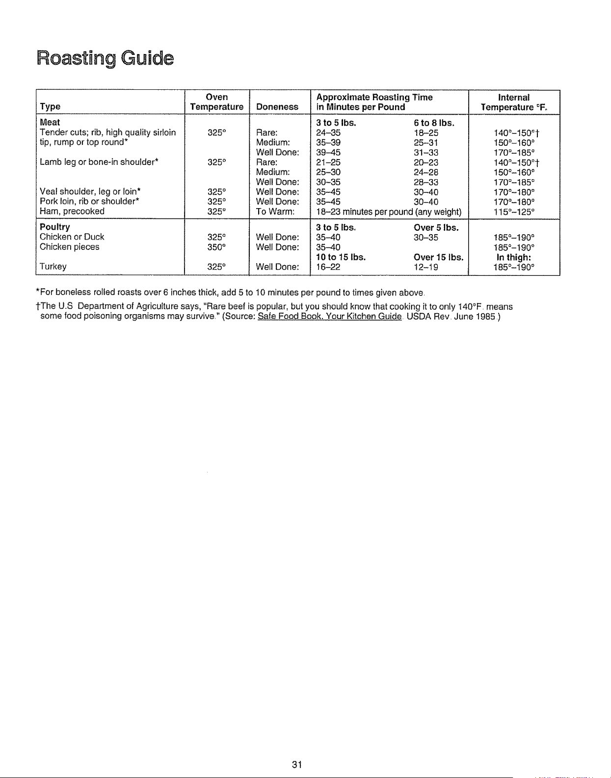
Roasting Guide
Type
Meat
Tender cuts; rib, high quality sirloin
tip, rump or top round*
Lamb leg or bone-in shoulder*
Veal shoulder, leg or loin*
Pork loin, rib or shoulder*
Ham, precooked
Poultry
Chicken or Duck
Chicken pieces
Turkey
Oven Approximate Roasting Time Internal
Temperature Doneness in Minutes per Pound Temperature °F,
325 °
325 °
325 °
325 °
325 °
325 °
350 °
Rare:
Medium:
Well Done:
Rare:
Medium:
Well Done:
Well Done:
Well Done:
To Warm:
Well Done:
Well Done:
Well Done:
3 to 5 Ibs. 6 to 8 Ibs.
24-35 18-25
35-39 25-3t
39-45 31-33
21-25 20-23
25-30 24-28
30-35 28-33
35-45 3O-4O
35-45 30-40
t8-23 minutes per pound (any weight)
3 to 5 Ibso Over 5 Ibs.
35-40 30-35
35-40
10 to 15 lbs. Over 15 Ibs.
t6-22 12-19325 °
140°-150 ° t
15O°- 160°
170°-185 °
140°-150° t
150°-160 °
170°-185 °
170°-180 °
170°-18O °
115°-125 °
185°-190 °
185°-190 °
In thigh:
185°-190 °
*For boneless rolled roasts over 6 inches thick, add 5 to 10 minutes per pound to times given above.
tThe U.S Department of Agriculture says, "Rare beef is popular, but you should know that cooking it to only t40_F, means
some food poisoning organisms may survive." (Source; Safe Food Book. Your Kitchen Guide USDA Rev. June t985.)
31
BroiRing
Broiling is cooking food by direct heat from above the
food. Your range has a convenient compartment
below the oven for broiling., it also has a specially
designed broiler pan and rack that allows dripping fat
to drain away from the high heat of the gas flame_
Distance from the heat source may be changed by
positioning the broiler pan and rack on one of the
three shelf positions in the broiler compartment--A
(bottom of broiler compartment),--B (middle) and C
(top),
Most fish and tender cuts of meat can be broiled.
Follow these steps to keep spattering and smoking to
a minimum.
The oven and broiler compartment doors must be
closed during broiling.
How to Broil
1. Broiler compartment does not need to be preheated
for broiling,
2. If meat has fat or gristle near the edge, cut vertical
slashes through it about 2 inches apart, but don't
cut into meat. We recommend that you trim fat to
prevent excessive smoking, leaving a layer about
1/8 inch thick,
3. Arrange food on rack and position the broiler pan
on the appropriate shelf in the broiler compartmenL
Placing food closer to flame sears the exterior and
increases surface browning of food, but also
increases spattering and the possibility of fats and
meat juices igniting,,
4. Close the broiler door and turn the OVEN CON-
TROL knob to BROIL.
5. Turn most foods once during cooking (the excep-
tion is thin fillets of fish; oil one side, place that side
down on broiler rack and cook without turning until
done)° Time food for about one-half the total cook-
ing time, turn food, then continue to cook to pre-
ferred donenes&
6. Turn OVEN CONTROL knob to OFF, Remove broil-
er pan from broiler compartment and serve food
immediately., Do not leave a soiled broiler pan and
rack inside the range,,
Use of Aluminum Foil
You can use aluminum
foil to line your broiler pan
and broiler rack° However,
you must mold the foil
tightly to the rack and cut
slits in it just like the rack,
Without the slits, the foil
will prevent fat and meat
I
juices from draining to the
broiler pan_ The juices could become hot enough to
catch on fire If you do not cut the slits, you are frying,
not broiling.
Questions & Answers
Q. When broiling, is it necessary to always use a
rack in the pan?
A. Yes,, Using the rack suspends the meat over the
pan,, As the meat cooks, the juices fall into the pan,
thus keeping meat drier. Juices are protected by
the rack and stay cooler, thus preventing excessive
spatter and smoking_
Q. Should I salt the meat before broiling?
A. No, Salt draws out the juices and allows them to
evaporate, Always salt after cooking, Turn meat
with tongs; piercing meat with a fork also allows
juices to escape. When broiling poultry or fish,
brush each side often with butter_
Why are my meats not turning out as brown as
they should?
Check to see if you are using the recommended
broil position,, Broil for longest period of time indi-
cated in the Broiling Guide,. Turn food only once
during broiling,
32
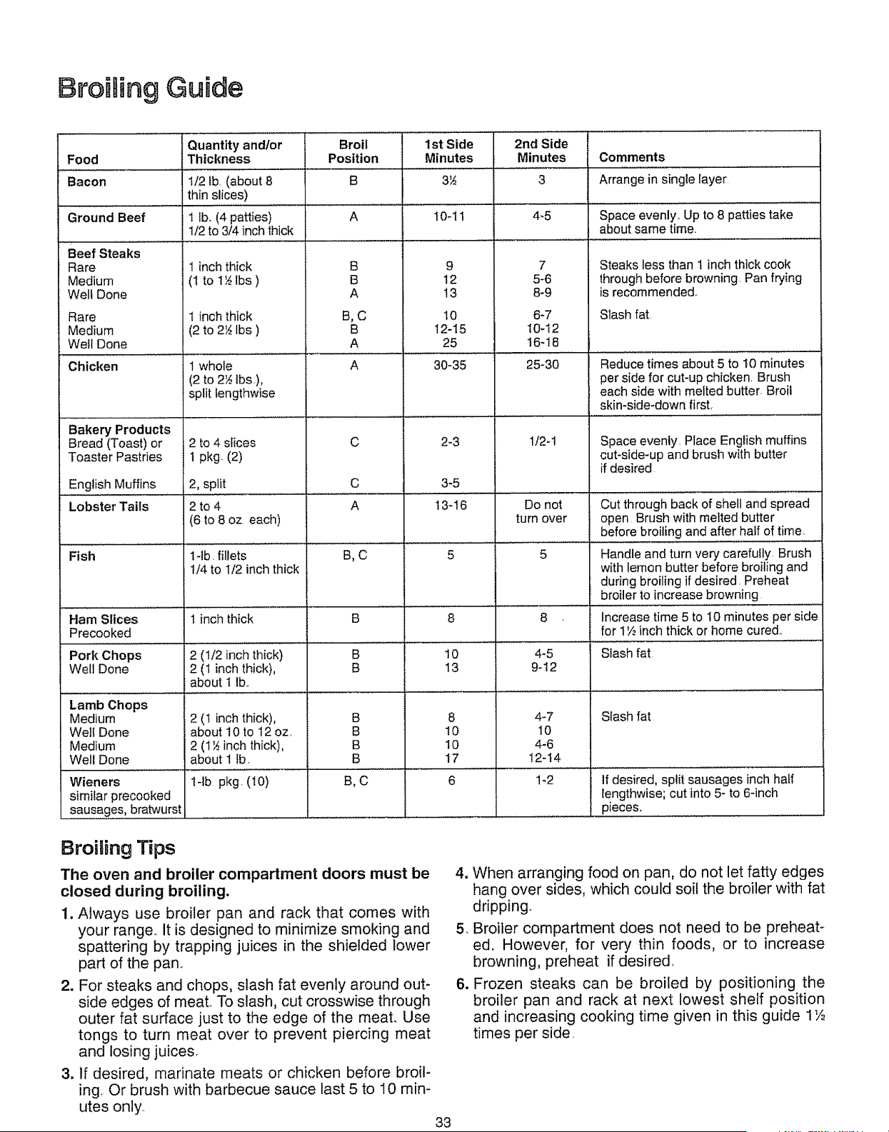
Broiling Guide
Quantity andlor Broil 1st Side 2nd Side
Food Thickness Position Minutes Minutes Comments
Bacon 1/2 ib. (about 8 B 3½ 3 Arrange in single layer
thin slices)
A I0-1 t 4-5 Space evenly. Up to 8 patties take
about same time.
Ground Beef
Beef Steaks
Rare
Medium
Well Done
Rare
Medium
WetI Done
Chicken
Bakery Products
Bread (Toast) or
Toaster Pastries
English Muffins
Lobster Tails
! lb. (4 patties)
1/2 to 3/4 inch thick
1 inch thick
(1 to 1'_ Ibs )
t inch thick
(2 to 2_ Ibs )
1 whole
(2 to 2½ tbs),
split lengthwise
2 to 4 stices
1 pkg (2)
2, split
2to4
(6 to 8 oz. each)
B
B
A
B,C
B
A
A
C
9 7
12 5-6
13 8-9
6-7
t0-12
16-18
25-30
2-3 1/2-1
3-5C
A
10
12-I5
25
30-35
Fish l-lb. fillets B, C 5 5
t/4 to I/2 inch thick
Ham Slices 1 inch thick B
Precooked
Pork Chops 2 (1/2 inch thick) B
Wet1 Done 2 (1 inch thick), B
about t lb..
Lamb Chops
Medium 2 (t inch thick),
Well Done about 10 to t 2 oz.
Medium 2 (1½ inch thick),
Well Done about I fb.
Wieners t4b pkg. (t0) B, C
similar precooked
sausages, bratwurst
8
Steaks less than t inch thick cook
through before browning. Pan frying
is recommended_
10
13
8
4-5
9-t2
Slash fat.
Reduce times about 5 to 10 minutes
per side for cut-up chicken. Brush
each side with melted butter. Broil
skin-side-down first,
Space evenly. Place English muffins
cut-side-up and brush with butter
if desired
!3-16 Do not Cut through back of shell and spread
turn over open Brush with melted butter
before broiling and after half of time.
Handle and turn very carefully. Brush
with lemon butter before broiling and
during broiling if desired. Preheat
broiler to increase browning
Increase time 5 to I0 minutes per side
for 1',4inch thick or home cure&
Slash fat
B
B
B
B
8
I0
10
17
4-7
10
4-6
12-14
Slash fat
if desired, split sausages inch half
lengthwise; cut into 5- to 6-inch
pieces, .............
1_2
8roiSing Tips
The oven and broiler compartment doors must be
closed during broiling.
1. Always use broiler pan and rack that comes with
your range., It is designed to minimize smoking and
spattering by trapping juices in the shielded lower
part of the pan,
2. For steaks and chops, slash fat evenly around out-
side edges of meat., To slash, cut crosswise through
outer fat surface just to the edge of the meat,, Use
tongs to turn meat over to prevent piercing meat
and losing juices,
3, if desired, marinate meats or chicken before broil-
ing, Or brush with barbecue sauce last 5 to 10 mira
utes only,,
4. When arranging food on pan, do not let fatty edges
hang over sides, which could soil the broiler with fat
dripping.
5. Broiler compartment does not need to be preheat-
ed. However, for very thin foods, or to increase
browning, preheat if desired
6. Frozen steaks can be broiled by positioning the
broiler pan and rack at next lowest shelf position
and increasing cooking time given in this guide 1',4
times per side
33
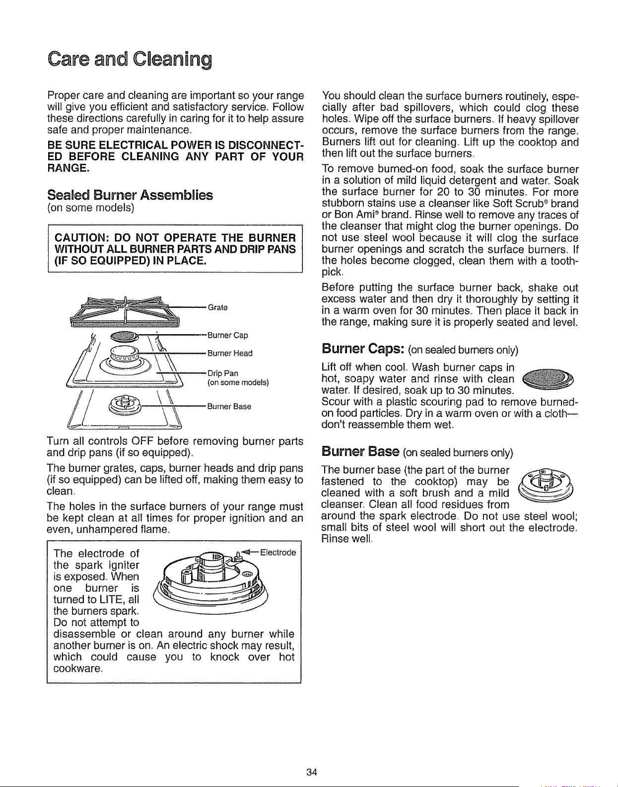
Care and Caear ing
Proper care and cleaning are important so your range
will give you efficient and satisfactory service, Follow
these directions carefully in caring for it to help assure
safe and proper maintenance.
BE SURE ELECTRICAL POWER iS DISCONNECT-
ED BEFORE CLEANING ANY PART OF YOUR
RANGE.
Sealed Burner Assemblies
(on some models)
CAUTION: DO NOT OPERATE THE BURNER
WITHOUT ALL BURNER PARTS AND DRIP PANS
(IF SO EQUIPPED) IN PLACE,
Grate
\,_. .--Burner Cap
\\
Pan
(on some modets)
Turn all controls OFF before removing burner parts
and drip pans (if so equipped)_
The burner grates, caps, burner heads and drip pans
(if so equipped) can be lifted off, making them easy to
clean_
The holes in the surface burners of your range must
be kept clean at all times for proper ignition and an
even, unhampered flame.
The electrode of "'_i'Electrode
the spark igniter
is exposed. When
one burner is
turned to LtTE, all
the burners spark.
Do not attempt to
disassemble or clean around any burner while
another burner is ono An electric shock may result,
which could cause you to knock over hot
cookware.
You should clean the surface burners routinely, espe-
cially after bad spillovers, which could clog these
hole& Wipe off the surface burners. If heavy spillover
occurs, remove the surface burners from the range.
Burners lift out for cleaning. Lift up the cooktop and
then lift out the surface burners.
To remove burned*on food, soak the surface burner
in a solution of mild liquid detergent and water. Soak
the surface burner for 20 to 30 minutes. For more
stubborn stains use a cleanser like Soft Scrub _ brand
or Bon AmP brand° Rinse well to remove any traces of
the cleanser that might clog the burner openings, Do
not use steel wool because it will clog the surface
burner openings and scratch the surface burners. If
the holes become clogged, clean them with a tooth-
pick.
Before putting the surface burner back, shake out
excess water and then dry it thoroughly by setting it
in a warm oven for 30 minutes. Then place it back in
the range, making sure it is properly seated and level.
Burner Caps: (on sealed burners only)
Lift off when cool. Wash burner caps in
hot, soapy water and rinse with clean
water_ If desired, soak up to 30 minutes.
Scour with a plastic scouring pad to remove burned-
on food particles. Dry in a warm oven or with a cloth--
don't reassemble them wet1.
Burner Bese (on sealed burners onEy)
The burner base (the part of the burner
fastened to the cooktop) may be
cleaned with a soft brush and a mild
cleanser, Clean all food residues from
around the spark electrode Do not use steel wool;
small bits of steel wool will short out the electrode,
Rinse well.
34
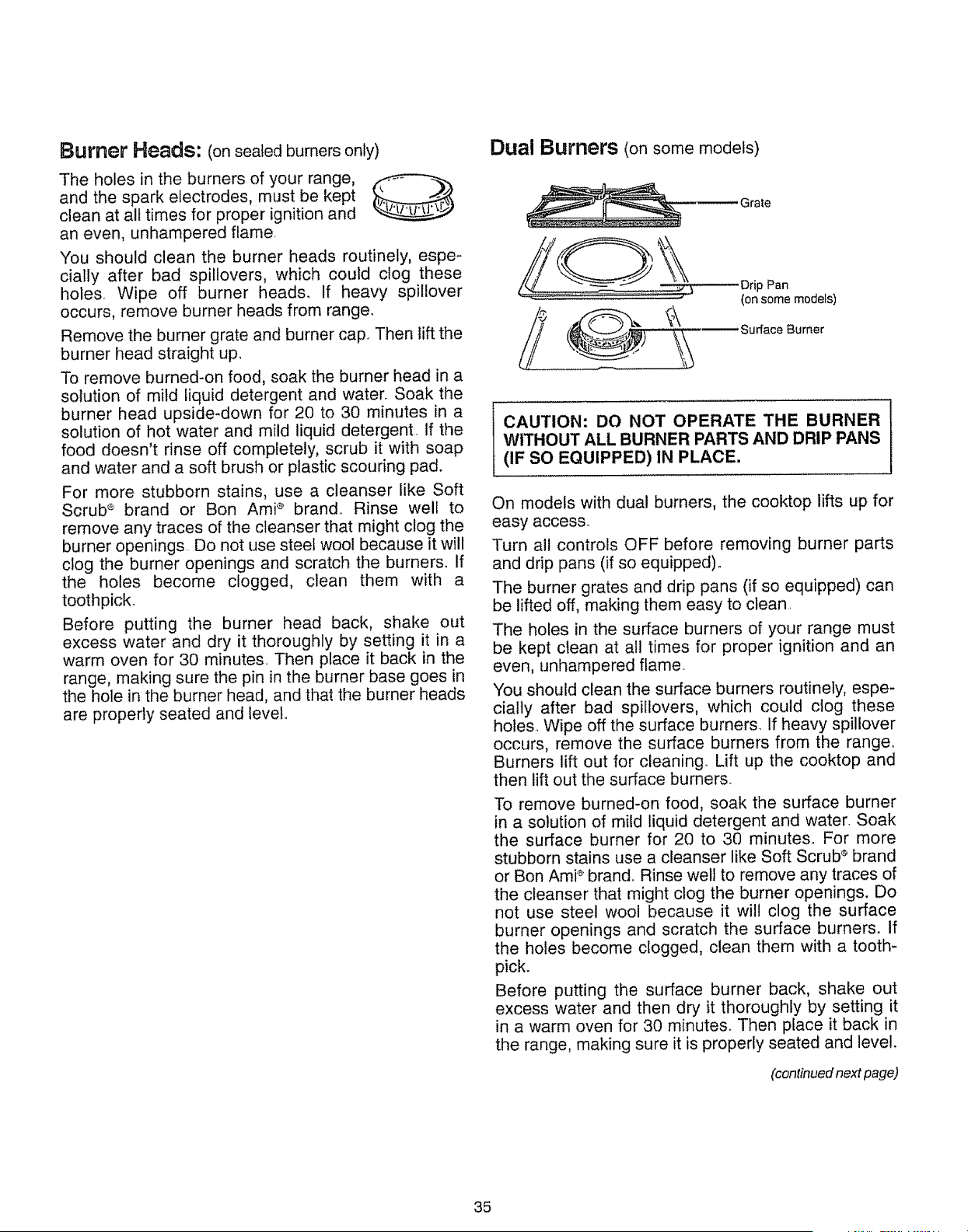
Burner Heads: (onsealed burners only)
The holes in the burners of your range,
and the spark electrodes, must be kept
clean at all times for proper ignition and
an even, unhampered flame.
You should clean the burner heads routinely, espe-
cially after bad spillovers, which could clog these
holes Wipe off burner heads. If heavy spillover
occurs, remove burner heads from range.
Remove the burner grate and burner cap.. Then lift the
burner head straight up_
To remove burned-on food, soak the burner head in a
solution of mild liquid detergent and water. Soak the
burner head upside-down for 20 to 30 minutes in a
solution of hot water and mild liquid detergent. If the
food doesn't rinse off completely, scrub it with soap
and water and a soft brush or plastic scouring pad.
For more stubborn stains, use a cleanser like Soft
Scrub s' brand or Bon Ami '_ brand_ Rinse well to
remove any traces of the cleanser that might clog the
burner openings. Do not use steef wool because it will
clog the burner openings and scratch the burners° If
the holes become clogged, clean them with a
toothpick_
Before putting the burner head back, shake out
excess water and dry it thoroughly by setting it in a
warm oven for 30 minutes Then place it back in the
range, making sure the pin in the burner base goes in
the hole in the burner head, and that the burner heads
are properly seated and level°
Dual Burners (on some models)
Grate
Drip Pan
(on some models)
_,_,_) \\\ , Surface Burner
CAUTION: DO NOT OPERATE THE BURNER
WITHOUT ALL BURNER PARTS AND DRIP PANS
(IF SO EQUIPPED) IN PLACE.
On models with dual burners, the cooktop lifts up for
easy access.
Turn all controls OFF before removing burner parts
and drip pans (if so equipped)_
The burner grates and drip pans (if so equipped) can
be lifted off, making them easy to clean
The holes in the surface burners of your range must
be kept clean at all times for proper ignition and an
even, unhampered flame.
You should clean the surface burners routinely, espe-
cially after bad spillovers, which could clog these
holes. Wipe off the surface burners. If heavy spillover
occurs, remove the surface burners from the range°
Burners lift out for cleaning. Lift up the cooktop and
then lift out the surface burners.
To remove burned-on food, soak the surface burner
in a solution of mild liquid detergent and water, Soak
the surface burner for 20 to 30 minutes° For more
stubborn stains use a cleanser like Soft Scrub s brand
or Bon Ami '_ brand_ Rinse well to remove any traces of
the cleanser that might clog the burner openings. Do
not use steel wool because it will clog the surface
burner openings and scratch the surface burners. If
the holes become clogged, clean them with a tooth-
pick_
Before putting the surface burner back, shake out
excess water and then dry it thoroughly by setting it
in a warm oven for 30 minutes. Then place it back in
the range, making sure it is properly seated and level,
(continued next page)
35
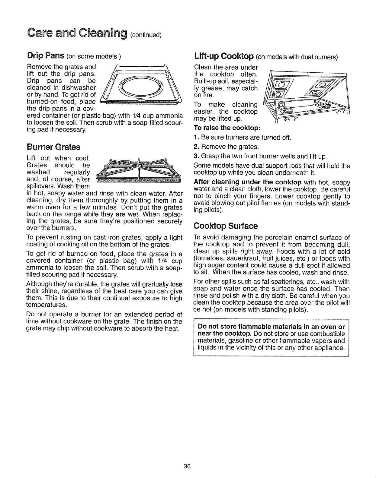
Care and Cneaning (continued)
Drip Pans (onsomemodels )
Remove the grates and
lift out the drip pans.
Drip pans can be
cleaned in dishwasher
or by hand. To get rid of
burned-on food, place
the drip pans in a cov-
ered container (or plastic bag) with 1/4 cup ammonia
to loosen the soil. Then scrub with a soap-filled scour-
ing pad if necessary°
Burner Grates
Lift out when coot..
Grates should be
washed regularly
and, of course, after
spillovers, Wash them
in hot, soapy water and rinse with clean water. After
cleaning, dry them thoroughly by putting them in a
warm oven for a few minutes. Don't put the grates
back on the range while they are wet. When replac-
ing the grates, be sure they're positioned securely
over the burners.
To prevent rusting on cast iron grates, apply a light
coating of cooking oil on the bottom of the grates°
To get rid of burned-on food, place the grates in a
covered container (or plastic bag) with 1/4 cup
ammonia to loosen the soilo Then scrub with a soap-
filled scouring pad if necessary,.
Although they're durable, the grates will gradually lose
their shine, regardless of the best care you can give
them,. This is due to their continual exposure to high
temperatures.
Do not operate a burner for an extended period of
time without cookware on the grate.. The finish on the
grate may chip without cookware to absorb the heat.
Lift-up Cooktop (onmodels with dual burners)
Clean the area under
the cooktop often.
Built-up soil, especial-
ly grease, may catch
on fire,
To make cleaning
easier, the cooktop
may be lifted up.
To raise the cook'top:
1. Be sure burners are turned off_
2. Remove the grates.
3. Grasp the two front burner wells and lift up.,
Some models have dual support rods that will hold the
cooktop up while you clean underneath it.
After cleaning under the cooktop with hot, soapy
water and a clean cloth, lower the cooktop° Be careful
not to pinch your fingers. Lower cooktop gently to
avoid blowing out pilot flames (on models with stand-
ing pilots).
Cooktop Surface
To avoid damaging the porcelain enamel surface of
the cooktop and to prevent it from becoming dull,
clean up spills right away_ Foods with a lot of acid
(tomatoes, sauerkraut, fruit juices, etc.) or foods with
high sugar content could cause a dull spot if allowed
to sit. When the surface has cooled, wash and rinse,.
For other spills such as fat spatterings, etc°, wash with
soap and water once the surface has cooled. Then
rinse and polish with a dry cloth. Be careful when you
clean the cooktop because the area over the pilot will
be hot (on models with standing pilots).
Do not store flammable materials in an oven or
near the cooktop. Do not store or use combustible
materials, gasoline or other flammable vapors and
liquids in the vicinity of this or any other appliance.
36
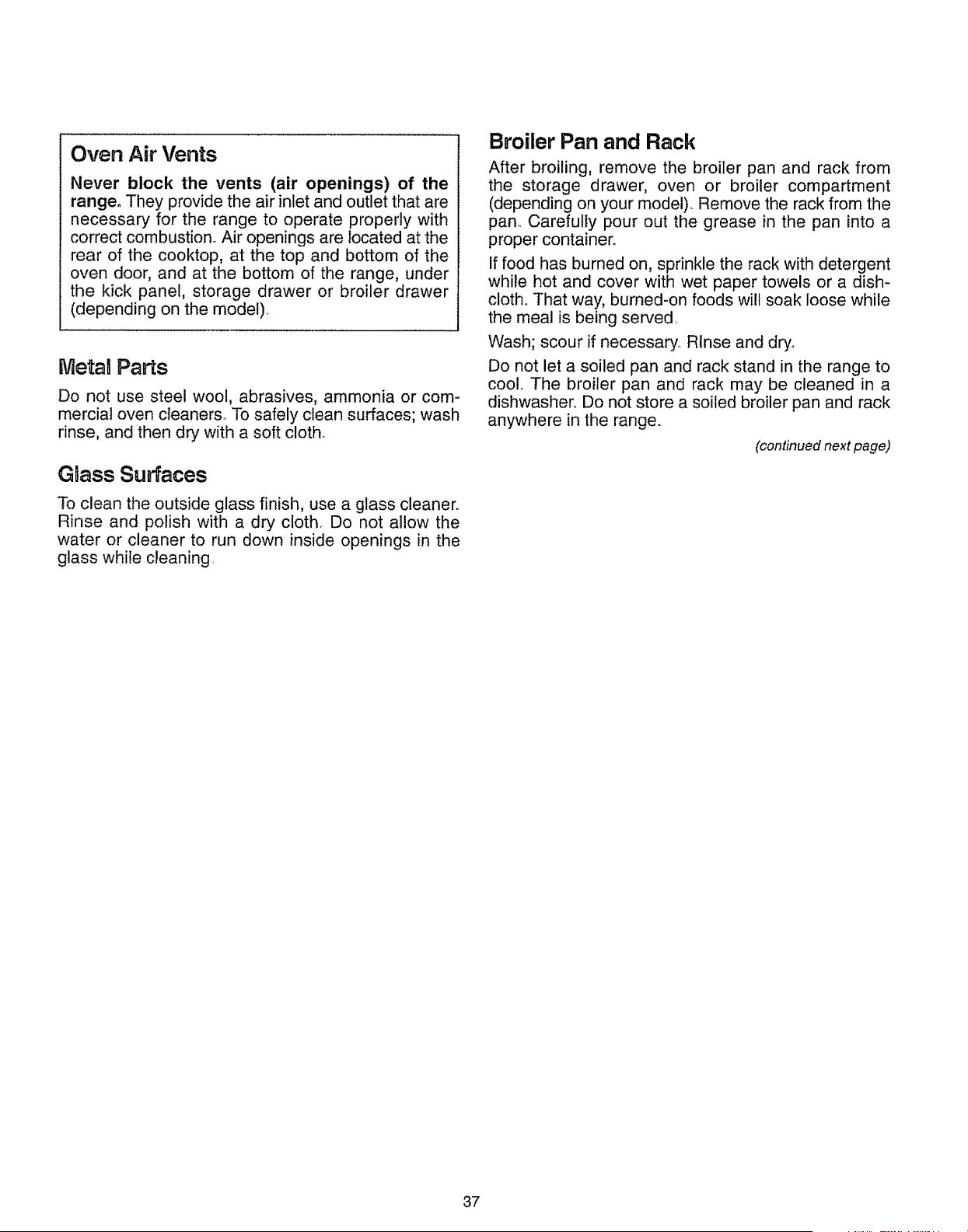
Oven Air Vents
Never block the vents (air openings) of the
range. They provide the air inlet and outlet that are
necessary for the range to operate properly with
correct combustion. Air openings are located at the
rear of the cooktop, at the top and bottom of the
oven door, and at the bottom of the range, under
the kick panel, storage drawer or broiler drawer
(depending on the model)..
MetaB Parts
Do not use steel wool, abrasives, ammonia or com-
mercial oven cleaners° To safely clean surfaces; wash
rinse, and then dry with a soft cloth_
GmassSurfaces
To clean the outside glass finish, use a glass cleaner.
Rinse and polish with a dry cloth. Do not allow the
water or cleaner to run down inside openings in the
glass while cleaning.
Broiler Pan and Rack
After broiling, remove the broiler pan and rack from
the storage drawer, oven or broiler compartment
(depending on your model). Remove the rack from the
pan_ Carefully pour out the grease in the pan into a
proper container.
If food has burned on, sprinkle the rack with detergent
while hot and cover with wet paper towels or a dish-
cloth_ That way, burned-on foods will soak loose while
the meal is being served.
Wash; scour if necessary_ Rinse and dry_
Do not let a soiled pan and rack stand in the range to
cool The broiler pan and rack may be cleaned in a
dishwasher.. Do not store a soiled broiler pan and rack
anywhere in the range.
(continued next page)
37
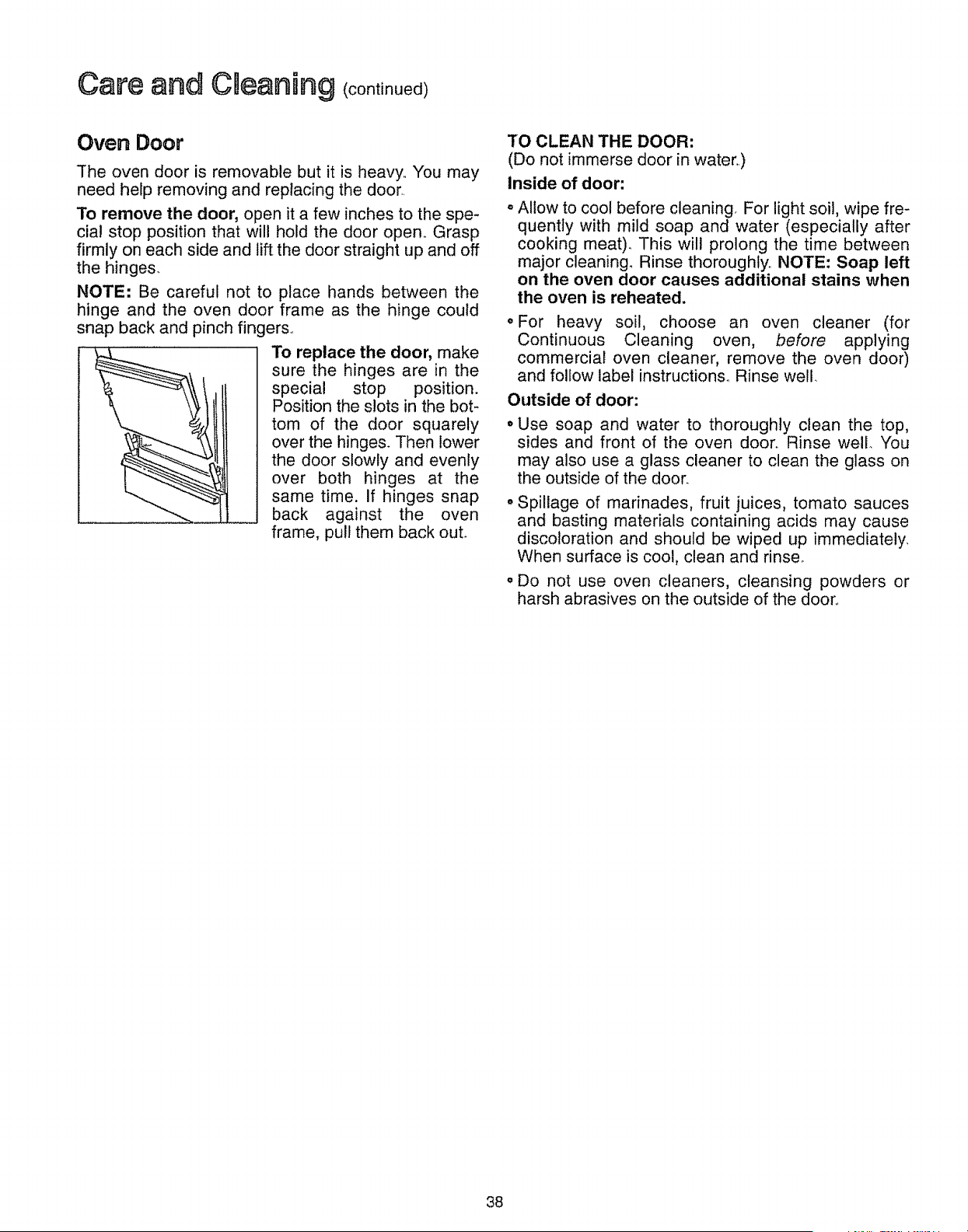
Care and Cneaning Icoot nuedt
Oven Door
The oven door is removable but it is heavy.. You may
need help removing and replacing the door.
To remove the door, open it a few inches to the spe-
cial stop position that will hold the door open. Grasp
firmly on each side and lift the door straight up and off
the hinges.
NOTE: Be careful not to place hands between the
hinge and the oven door frame as the hinge could
snap back and pinch fingers..
To replace the door, make
sure the hinges are in the
special stop position.
Position the slots in the bot-
tom of the door squarely
over the hinges. Then lower
the door slowly and evenly
over both hinges at the
same time. If hinges snap
back against the oven
frame, pull them back out.
TO CLEAN THE DOOR:
(Do not immerse door in water.)
Inside of door:
Allow to cool before cleaning, For light soil, wipe fre-
quently with mild soap and water (especially after
cooking meat). This will prolong the time between
major cleaning° Rinse thoroughly,, NOTE: Soap left
on the oven door causes additional stains when
the oven is reheated.
For heavy soil, choose an oven cleaner (for
Continuous Cleaning oven, before applying
commercial oven cleaner, remove the oven door)
and follow label instructions_ Rinse well.
Outside of door:
Use soap and water to thoroughly clean the top,
sides and front of the oven door. Rinse well. You
may also use a glass cleaner to clean the glass on
the outside of the door.
• Spillage of marinades, fruit juices, tomato sauces
and basting materials containing acids may cause
discoloration and should be wiped up immediately.
When surface is cool, clean and rinse°
,, Do not use oven cleaners, cleansing powders or
harsh abrasives on the outside of the door..
38
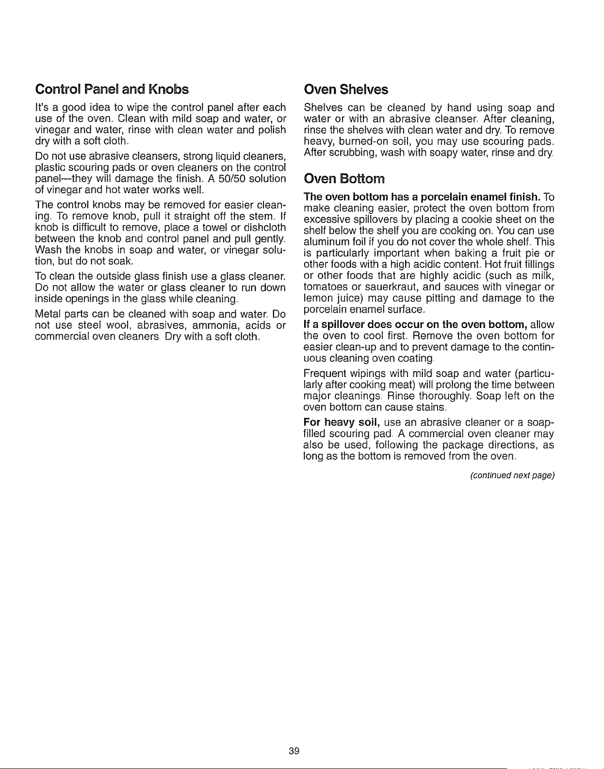
Control Panel and Knobs
It's a good idea to wipe the control panel after each
use of the oven.. Clean with mild soap and water, or
vinegar and water, rinse with clean water and polish
dry with a soft cloth.
Do not use abrasive cleansers, strong liquid cleaners,
plastic scouring pads or oven cleaners on the control
panel--they wilt damage the finish. A 50/50 solution
of vinegar and hot water works well.
The control knobs may be removed for easier clean-
ing. To remove knob, pull it straight off the stem. If
knob is difficult to remove, place a towel or dishcloth
between the knob and control panel and pull gently.
Wash the knobs in soap and water, or vinegar solu-
tion, but do not soak.
To clean the outside glass finish use a glass cleaner.
Do not allow the water or glass cleaner to run down
inside openings in the glass while cleaning.
Metal parts can be cleaned with soap and water.. Do
not use steel wool, abrasives, ammonia, acids or
commercial oven cleaners. Dry with a soft cloth°
Oven Shelves
Shelves can be cleaned by hand using soap and
water or with an abrasive cleanser, After cleaning,
rinse the shelves with clean water and dry. To remove
heavy, burned-on soil, you may use scouring pads..
After scrubbing, wash with soapy water, rinse and dry.
Oven Bottom
The oven bottom has a porcelain enamel finish. To
make cleaning easier, protect the oven bottom from
excessive spillovers by placing a cookie sheet on the
shelf below the shelf you are cooking on. You can use
aluminum foil if you do not cover the whole shelf. This
is particularly important when baking a fruit pie or
other foods with a high acidic content. Hot fruit fillings
or other foods that are highly acidic (such as milk,
tomatoes or sauerkraut, and sauces with vinegar or
lemon juice) may cause pitting and damage to the
porcelain enamel surface.
If a spillover does occur on the oven bottom, allow
the oven to cool firsL Remove the oven bottom for
easier clean-up and to prevent damage to the contin-
uous cleaning oven coating
Frequent wipings with mild soap and water (particu-
larly after cooking meat) will prolong the time between
major cleanings Rinse thoroughly.. Soap left on the
oven bottom can cause stain&
For heavy soil, use an abrasive cleaner or a soap-
filled scouring pad, A commercial oven cleaner may
also be used, following the package directions, as
long as the bottom is removed from the oven..
(continued next page)
39
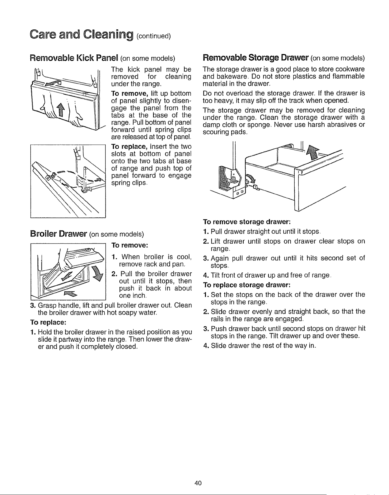
Care and CDeaning (ooot,ooed
Removable Kick Panel (on somemodels)
The kick panel may be
removed for cleaning
under the range°
To remove, lift up bottom
of panel slightly to disen-
gage the panel from the
tabs at the base of the
range° Pull bottom of panel
forward until spring clips
are released at top of panel,
To replace, insert the two
slots at bottom of panel
onto the two tabs at base
of range and push top of
panel forward to engage
spring clips,
Removable Storage Drawer (onsomemodels)
The storage drawer is a good place to store cookware
and bakeware, Do not store plastics and flammable
material in the drawer,.
Do not overload the storage drawer. If the drawer is
too heavy, it may slip off the track when opened°
The storage drawer may be removed for cleaning
under the range° Clean the storage drawer with a
damp cloth or sponge_ Never use harsh abrasives or
scouring pads,,
Broiler Drawer (on somemodels)
3. Grasp handle, lift and
To remove:
1. When broiler is cool,
remove rack and pan,
2. Pull the broiler drawer
out until it stops, then
push it back in about
one inch
3ulf broiler drawer out,, Clean
the broiler drawer with hot soapy water.
To replace:
1. Hold the broiler drawer in the raised position as you
slide it partway into the range. Then lower the draw-
er and push it completely closed.
To remove storage drawer:
1. Pull drawer straight out until it stops
2, Lift drawer until stops on drawer clear stops on
range.
3. Again pull drawer out until it hits second set of
stops,.
4. Tilt front of drawer up and free of range,
To replace storage drawer"
1. Set the stops on the back of the drawer over the
stops in the range,
2. Slide drawer evenly and straight back, so that the
rails in the range are engaged
3. Push drawer back until second stops on drawer hit
stops in the range. Tilt drawer up and over these.
4. Slide drawer the rest of the way in.
40
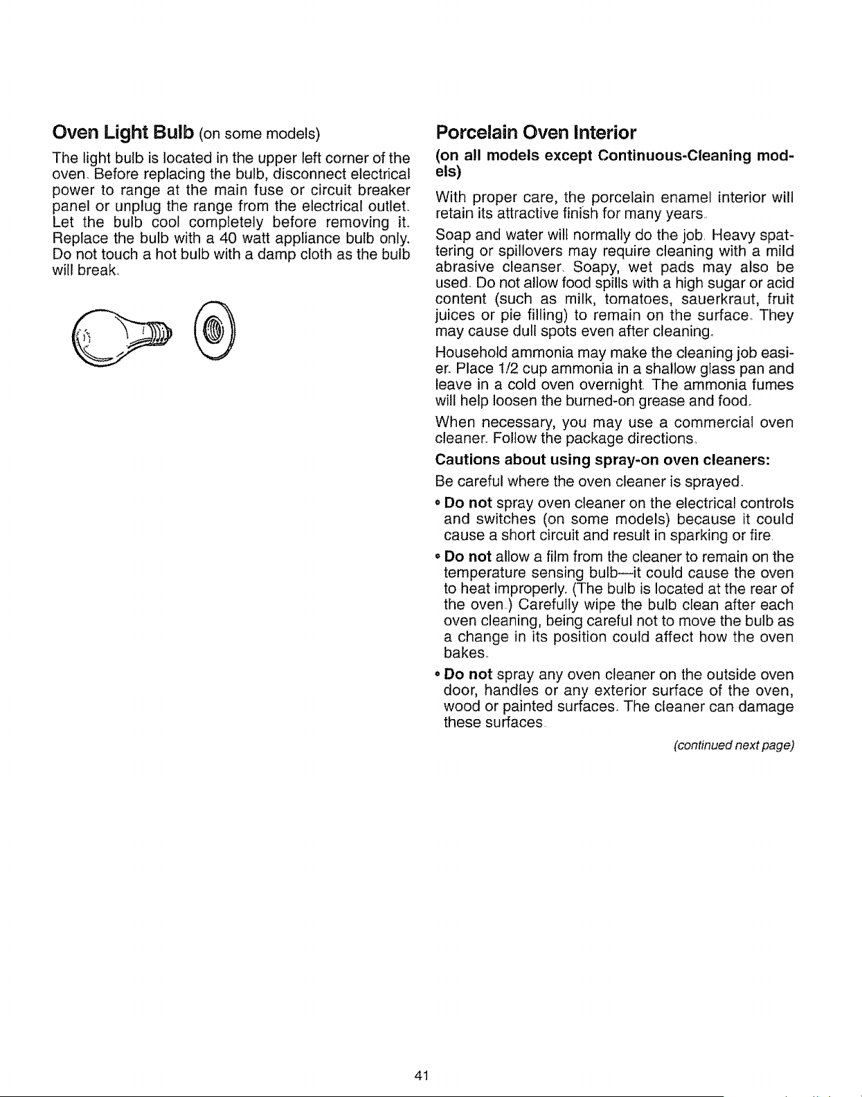
Oven Light Bulb (onsomemodels)
The light bulb is located in the upper left corner of the
oven. Before replacing the bulb, disconnect electrical
power to range at the main fuse or circuit breaker
panel or unplug the range from the electrical outlet.
Let the bulb cool completely before removing iL
Replace the bulb with a 40 watt appliance bulb only.
Do not touch a hot bulb with a damp cloth as the bulb
will break.
Porcelain Oven Interior
(on all models except Continuous-Cleaning mod-
els)
With proper care, the porcelain enamel interior will
retain its attractive finish for many years,
Soap and water will normally do the job. Heavy spat-
tering or spillovers may require cleaning with a mild
abrasive cleanser, Soapy, wet pads may also be
used. Do not allow food spills with a high sugar or acid
content (such as milk, tomatoes, sauerkraut, fruit
juices or pie filling) to remain on the surface_ They
may cause dull spots even after cleaning°
Household ammonia may make the cleaning job easi-
er. Place t/2 cup ammonia in a shallow glass pan and
leave in a cold oven overnight The ammonia fumes
will help loosen the burned-on grease and food_
When necessary, you may use a commercial oven
cleaner.. Follow the package directions,
Cautions about using spray-on oven cleaners:
Be careful where the oven cleaner is sprayed_
o Do not spray oven cleaner on the electrical controls
and switches (on some models) because it could
cause a short circuit and result in sparking or fire.
o Do not allow a film from the cleaner to remain on the
temperature sensing bulb--it could cause the oven
to heat improperly. (The bulb is located at the rear of
the oven..) Carefully wipe the bulb clean after each
oven cleaning, being careful not to move the bulb as
a change in its position could affect how the oven
bakes°
• Do not spray any oven cleaner on the outside oven
door, handles or any exterior surface of the oven,
wood or painted surfaces° The cleaner can damage
these surfaces
(continued next page)
41
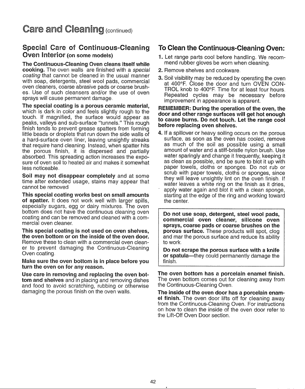
Care and €Meaning(cont oued)
Specia Care of Continuous-Cleaning
Oven interior (on some models)
The Continuous-Cleaning Oven cleans itself while
cooking. The oven walls are finished with a special
coating that cannot be cleaned in the usual manner
with soap, detergents, steel wool pads, commercial
oven cleaners, coarse abrasive pads or coarse brush-
es Use of such cleansers and/or the use of oven
sprays will cause permanent damage
The special coating is a porous ceramic material,
which is dark in color and feels slightly rough to the
touch° If magnified, the surface would appear as
peaks, valleys and sub-surface "tunnels_" This rough
finish tends to prevent grease spatters from forming
little beads or droplets that run down the side walls of
a hard-surface oven liner, leaving unsightly streaks
that require hand cleaning, Instead, when spatter hits
the porous finish, it is dispersed and partially
absorbed. This spreading action increases the expo-
sure of oven soil to heated air and makes it somewhat
less noticeable
Soil may not disappear completely and at some
time after extended usage, stains may appear that
cannot be removed
This special coating works best on small amounts
of spatter. It does not work well with larger spills,
especially sugars, egg or dairy mixtures The oven
bottom does not have the continuous cleaning oven
coating and can be removed and cleaned with a com-
mercial oven cleaner
This special coating is not used on oven shelves,
the oven bottom or on the inside of the oven door.
Remove these to clean with a commercial oven clean-
er to prevent damaging the Continuous-Cleaning
Oven coating
Make sure the oven bottom is in place before you
turn the oven on for any reason.
Use care in removing and replacing the oven bot-
tom and shelves and in placing and removing dishes
and food to avoid scratching, rubbing or otherwise
damaging the porous finish on the oven walls
To Clean the Continuous-Cleaning Oven:
1. Let range parts cool before handling We recom-
mend rubber gloves be worn when cleaning
2. Remove shelves and cookware
3. Soil visibility may be reduced by operating the oven
at 400°R Close the door and turn OVEN CON-
TROL knob to 400°E Time for at least four hours,,
Repeated cycles may be necessary before
improvement in appearance is apparenL
REMEMBER: During the operation of the oven, the
door and other range surfaces will get hot enough
to cause burns. Do not touch. Let the range cool
before replacing oven shelves.
4. If a spillover or heavy soiling occurs on the porous
surface, as soon as the oven has cooled, remove
as much of the soil as possible using a small
amount of water and a stiff-bristle nylon brush. Use
water sparingly and change it frequently, keeping it
as clean as possible, and be sure to blot it up with
paper towels, cloths or sponges_ Do not rub or
scrub with paper towels, cloths or sponges, since
they will leave unsightly lint on the oven finish If
water leaves a white ring on the finish as it dries,
apply water again and blot it with a clean sponge,
starting at the edge of the ring and working toward
the center.
Do not use soap, detergent, steel wool pads,
commercial oven cleaner, silicone oven
sprays, coarse pads or coarse brushes on the
porous surface. These products will spot, clog
and mar the porous surface and reduce its ability
to work.
Do not scrape the porous surface with a knife
or spatula--they could permanently damage the
finish_
The oven bottom has a porcelain enamel finish.
The oven bottom comes out for cleaning away from
the Continuous-Cleaning Oven
The inside of the oven door has a porcelain enam-
el finish. The oven door lifts off for cleaning away
from the Continuous_Cleaning Oven. For instructions
on how to clean the inside of the oven door refer to
the Lift-Off Oven Door section.
42
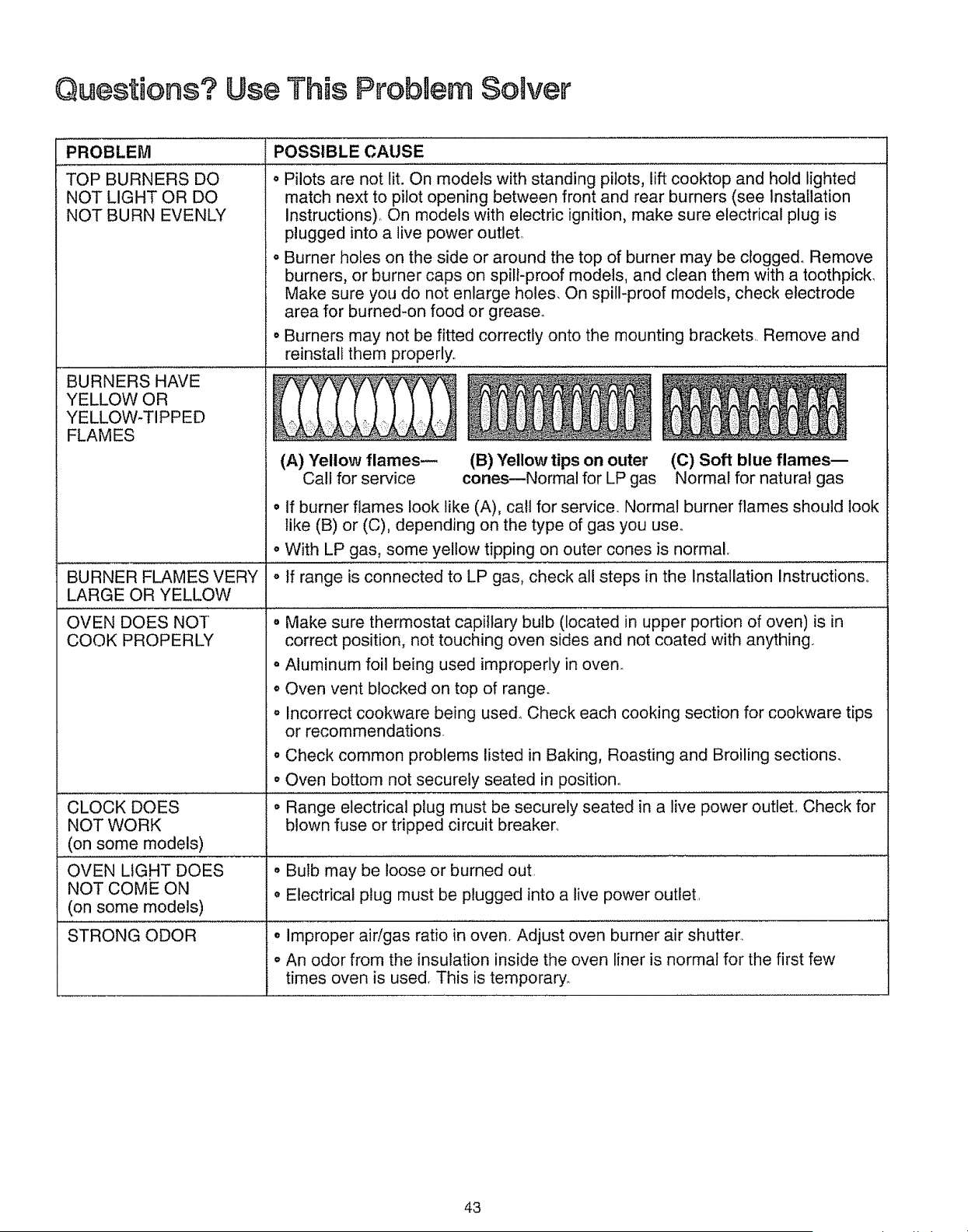
Questiens? Use This Probaem Selver
PROBLEM POSSIBLE CAUSE
TOP BURNERS DO o Pilots are not lit. On models with standing pilots, lift cooktop and hold lighted
NOT LIGHT OR DO match next to pilot opening between front and rear burners (see Installation
NOT BURN EVENLY instructions). On models with electric ignition, make sure electrical plug is
plugged into a live power outlet.
o Burner holes on the side or around the top of burner may be clogged._ Remove
burners, or burner caps on spill-proof models, and clean them with a toothpick,
Make sure you do not enlarge holes. On spill-proof models, check electrode
area for burned-on food or grease_
o Burners may not be fitted correctly onto the mounting brackets.. Remove and
reinstall them properly..
BURNERS HAVE
YELLOW OR
YELLOW-TIPPED
FLAMES
(A) "Yellow flames--
Call for service
(B) Yellow tips on outer
cones--Normal for LP gas
(C) Soft blue flames--
Normal for natural gas
• If burner flames look like (A), call for service. Normal burner flames should look
like (B) or (C), depending on the type of gas you use.
o With LP gas, some yellow tipping on outer cones is normal.
range is connected to LP gas, check all steps in the Installation instructions.
LARGE OR YELLOW
OVEN DOES NOT o Make sure thermostat capillary bulb (located in upper portion of oven) is in
COOK PROPERLY correct position, not touching oven sides and not coated with anything.
o Aluminum foil being used improperly in oven.
° Oven vent blocked on top of range.
o Incorrect cookware being use& Check each cooking section for cookware tips
or recommendations.
o Check common problems listed in Baking, Roasting and Broiling sections.
• Oven bottom not securely seated in position°
CLOCK DOES • Range electrical plug must be securely seated in a live power outlet.. Check for
NOT WORK blown fuse or tripped circuit breaker_
(on some models)
OVEN LIGHT DOES • Bulb may be loose or burned out.
NOT COME ON • Electrical plug must be plugged into a live power outleL
(on some models)
STRONG ODOR
o Improper air!gas ratio in oven. Adjust oven burner air shutter.
o An odor from the insulation inside the oven liner is normal for the first few
times oven is used. This is temporary.
43
KENMORE GAS RANGE WARRANTY
FULL ONE-YEAR WARRANTY ON THE FUNCTIONING OF
ALL PARTS EXCEPT GLASS PARTS
if, within one year from the date of installation, any part, other than a glass part, fails to function properly
due to a defect in material or workmanship, Sears will repair or replace it, free of charge,
FULL 30-DAY WARRANTY ON GLASS PARTS AND FINISH OF PORCELAIN ENAMEL,
PAINTED OR BRIGHT METAL FINISHED PARTS
If, within 30 days from the date of installation, any glass part or the finish on any porcelain enamel, painted
or bright metal part is defective in material or workmanship, Sears will replace the part, free of charge,
FULL 90-DAY WARRANTY ON MECHANICAL ADJUSTMENTS
For 90 days from the date of installation, Sears will provide, free of charge, any mechanical adjustments
necessary for proper operation of the range, except for normal maintenance°
If the range is subjected to other than private family use, the above warranty coverage is effective for
only 90 days°
WARRANTY SERVICE IS AVAILABLE BY CONTACTING THE NEAREST
SEARS SERVICE CENTER/DEPARTMENT IN THE UNITED STATES.
This warranty applies only while this product is in use in the United States This warranty gives you
specific legal rights, and you may also have other rights which vary from state to state_
SEARS, ROEBUCK AND CO., DEPT. 731CR-W, SEARS TOWER, CHICAGO, IL 60684
Dear Customer: Our constant efforts are directed toward making sure your new Kenmore Range wilt arrive at your _
home in perfect condition and will give you proper performance, As part of these efforts, we feel it is our responsibility to
provide you with this warranty for your range, j
WE SERVICE WHAT WE SELL
"We Service What We Sell" is our assurance to you that you can depend on Sears for service because Sears service is nationwide
Your Kenmore Range has added value when you consider that Sears has a service unit near you staffed by Sears trained tech-
nician&oprofessional technicians specifically trained on Sears appliances, having the parts, tools and equipment to ensure the1
we meet our pledge to you_"We Service what We SeIl!"
TO FURTHER ADD TO THE VALUE OF YOUR RANGE
Kenmore ranges are designed, manufactured and tested
for years of dependable operation. Yet, any modern appli-
ance may require service from time to time. The Sears
warranty plus the Sears Maintenance Agreement provides
protection from unexpected repair bills and assures you
of enjoying maximum range efficiency.
Here's a comparative warranty and Maintenance Agree-
ment chart showing you the benefits of a Sears Range
Maintenance AgreemenL
CONTACT YOUR SEARS SALESPERSON OR LOCAL
SEARS SERVICE CENTER TODAY AND PURCHASE A
SEARS MAINTENANCE AGREEMENT.
BUY A SEARS MAINTENANCE AGREEMENT.
Years of Ownership Coverage 1st Year 2nd Year 3rd Year
Replacementof Defective
1 padsother[han W MA MA
Porcelain or GLass
90 Days
Fult
2 Mechanical Adjustment Warranty MA MA
MA
30 Days
Full
3 Porcelain andGlass Parts Warranty MA MA
MA
Annual Preventive
4 Maintenance Check W MA MA
at your request
W - Warranty MA - Maintenance Agreement
America's Best Se ing Appliance Brand
Sold by SEARS, ROEBUCK AND CO,, CHICAGO, IL 60684
This book is printed on recycled paper. Printed in U S A. 610t 1 61118 71221
[ Part No. SR4215 ] 164D2764P0286111161018 61218612ti7!32171228
512 CG
71328 71721 7182_
71631 71728 72711
71638 71821 7271_
72725