Loading ...
Loading ...
Loading ...
49-6000245 Rev. 0 17
INSTALLATION INSTRUCTIONS
Installation Instructions
TO FILL THE WATER HEATER
WARNING
Risk of Unit Damage - The
tank must be full of water before the water heater
is turned on. The water heater warranty does not
cover damage or failure resulting from operation
with an empty or partially empty tank.
1. Check that the drain valve is completely closed.
2. Open the shut-off valve in the cold water supply
line.
3. Open hot water faucets slowly, allowing air to vent
from the water heater and pipes.
4. Wait until there is a steady flow of water from the
hot water faucets; this indicates that the water
heater is full.
5. Check connections and pipes for any leakage.
When the water heater is first filled with water,
condensation may form on the tank and fittings.
During use, condensation can be caused by a heavy
water draw and very cold inlet water temperature.
This condition is not unusual and will resolve after
the water is heated. If condensation persists,
examine fittings for potential leaks and repair as
required.
TEMPERATURE AND PRESSURE
RELIEF VALVE
WARNING
Risk of Unit Damage - The
pressure rating of the relief valve must not
exceed 150 PSI (1.03 MPa), the maximum working
pressure of the water heater as marked on the
rating plate.
A new combination temperature and pressure (T&P)
relief valve, complying with the Standard for Relief
Valves and Automatic Gas Shut-Off Devices for Hot
Water Supply Systems, ANSI Z21.22/CSA 4.4, is
supplied and must remain installed in the opening
provided and marked for this purpose on the water
heater. No valve of any type should be installed
between the relief valve and the tank. Local codes
shall govern the installation of relief valves.
The BTUH rating of the temperature and pressure
relief valve must not be less than the input rating
of the water heater as indicated on the rating plate
located on the front of the heater (1 watt=3.412
BTUH).
Connect the outlet of the relief valve to a suitable
open drain so that the discharge water cannot contact
live electrical parts or persons and to eliminate
potential water damage.
Piping used should be of a type approved for hot
water distribution. The discharge line must be no
smaller than the outlet of the valve and must pitch
downward from the valve to allow complete drainage
(by gravity) of the relief valve and discharge line. The
end of the discharge line should not be threaded or
concealed and should be protected from freezing.
No valve of any type, restriction or reducer coupling
should be installed in the discharge line.
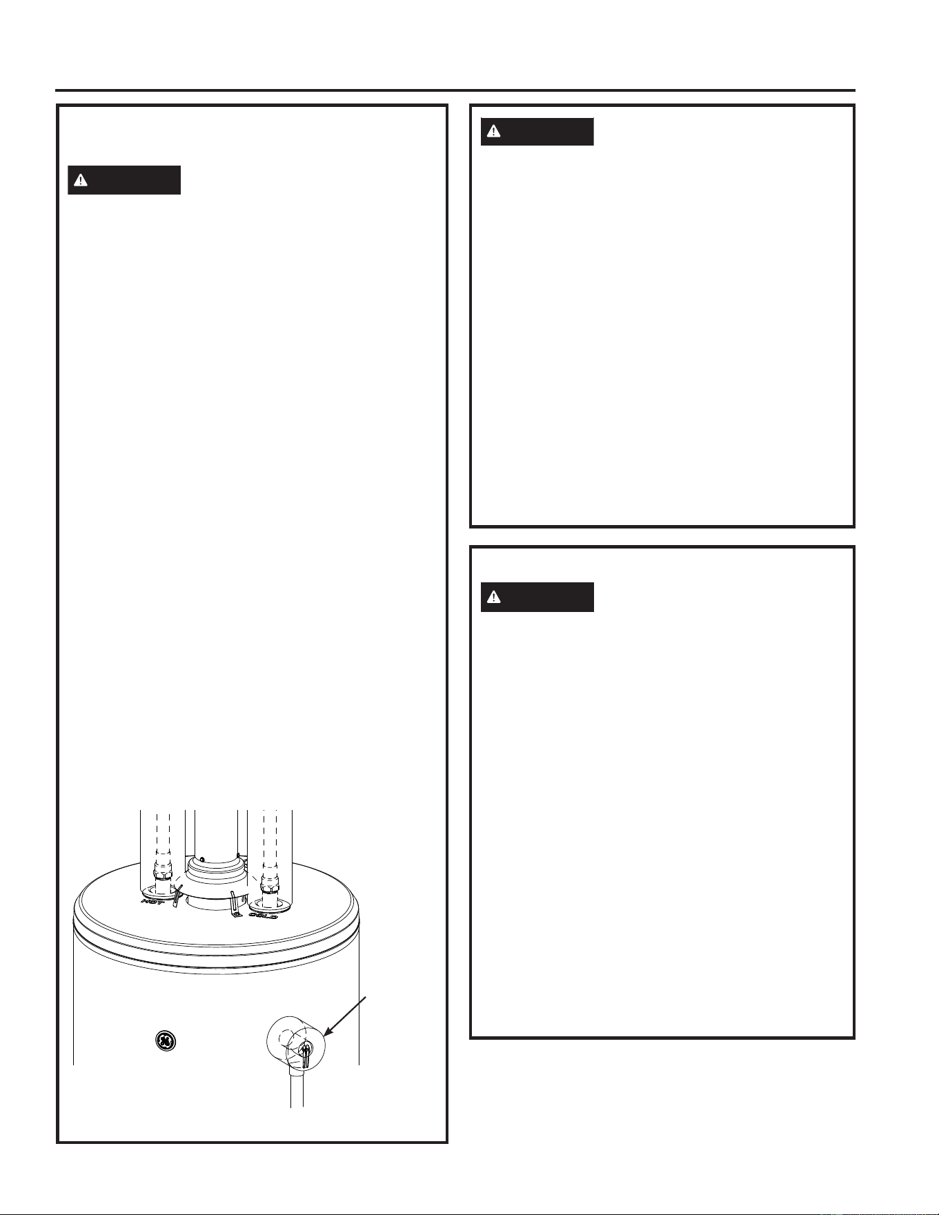
(Model appearance may vary)
CAUTION
To reduce the risk of excessive pressures and
temperatures in this water heater, install temperature
and pressure protective equipment required by local
codes and no less than a combination temperature
and pressure relief valve certified by a nationally
recognized testing laboratory that maintains periodic
inspection of production of listed equipment or
materials, as meeting the requirements for Relief
Valves and Automatic Gas Shut-Off Devices for
Hot Water Supply Systems, ANSI Z21.22 /CSA
4.4. This valve must be marked with a maximum
set pressure not to exceed the marked maximum
working pressure of the water heater. Install the
valve into an opening provided and marked for this
purpose in the water heater, and orient it or provide
tubing so that any discharge from the valve exits
only within 6 inches above, or at any distance below,
the structural floor, and does not contact any live
electrical part. The discharge opening must not be
blocked or reduced in size under any circumstance.
Relief Valve
Insulation
Loading ...
Loading ...
Loading ...