Loading ...
Loading ...
Loading ...
_, WARNING:Theroutershouldneverbe
connectedtoapowersupplywhenyouare
assemblingparts,makingadjustments,cleaning,
performingmaintenance,orwhenthetoolisnotin
use.Disconnectingthetoolpreventsaccidental
startingthatcouldcauseseriousinjury.
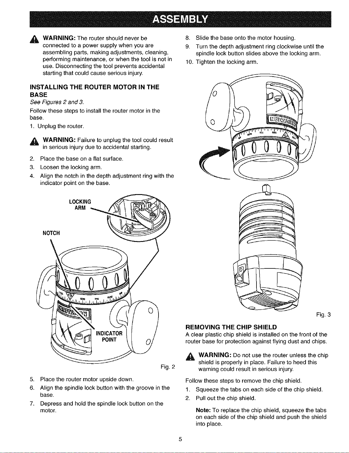
INSTALLING THE ROUTER MOTOR IN THE
BASE
See Figures 2 and 3.
Follow these steps to install the router motor in the
base.
1. Unplug the router.
_, WARNING: Failure to unplug the tool could result
in serious injury due to accidental starting.
2. Place the base on a flat surface.
3. Loosen the locking arm.
4. Align the notch in the depth adjustment ring with the
indicator point on the base.
8. Slide the base onto the motor housing.
9. Turn the depth adjustment ring clockwise until the
spindle lock button slides above the locking arm.
10. Tighten the locking arm.
LOCKING
ARM
NOTCH
Fig. 2
5. Place the router motor upside down.
6. Align the spindle lock button with the groove in the
base.
7. Depress and hold the spindle lock button on the
motor.
Fig. 3
REMOVING THE CHIP SHIELD
A clear plastic chip shield is installed on the front of the
router base for protection against flying dust and chips.
,_ WARNING: Do not use the router unless the chip
shield is properly in place. Failure to heed this
warning could result in serious injury.
Follow these steps to remove the chip shield.
1. Squeeze the tabs on each side of the chip shield.
2. Pull out the chip shield.
Note: To replace the chip shield, squeeze the tabs
on each side of the chip shield and push the shield
into place.
5
Loading ...
Loading ...
Loading ...