Loading ...
Loading ...
Loading ...
WARNING
Neverattemptto
make any adjust-
ments while the
engine is running,
except where speci-
i fied in the operator's
manual.
i Never attempt to
iadjust the brakes
_wh ie the engine
i is running. Always
idisengage PTO, move
::shift lever into neutral
position, stop engine
and remove key to
iprevent unintended
istarting.
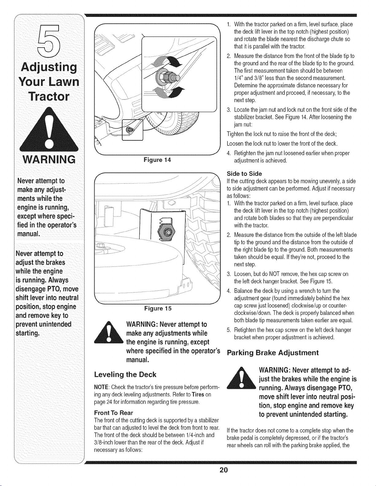
Figure 14
1. Withthe tractorparkedona firm,levelsurface,place
the deck lift leverin the top notch(highestposition)
androtatethe blade nearestthe dischargechute so
thatitis parallelwiththe tractor.
2. Measurethe distancefromthe frontofthe bladetip to
the groundand the rearof the blade tip to the ground.
Thefirst measurementtakenshouldbe between
1/4"and 3/8" less than thesecondmeasurement.
Determinethe approximatedistancenecessaryfor
properadjustmentandproceed,if necessary,to the
nextstep.
3. Locatethejam nut andlocknut onthe frontsideof the
stabilizerbracket.See Figure14.After looseningthe
jam nut:
Tightenthe lock nutto raisethefront of the deck;
Loosenthe lock nut to lowerthefrontof the deck.
4. Retightenthe jam nut loosenedearlierwhen proper
adjustmentis achieved.
Figure 15
,_ WARNING: Never attempt to
make any adjustments while
the engine is running, except
where specified in the operator's
manual.
Leveling the Deck
NOTE:Checkthe tractor'stire pressurebeforeperform-
inganydeck levelingadjustments.Referto Tires on
page24 for informationregardingtire pressure.
Front To Rear
Thefrontof the cuttingdeckis supportedbya stabilizer
barthatcanadjustedto levelthe deckfromfrontto rear.
Thefrontof the deckshouldbebetween1/4-inchand
3/8-inchlowerthanthe rear of the deck.Adjustif
necessaryas follows:
Side to Side
If the cuttingdeckappearsto be mowingunevenly,a side
to side adjustmentcan be performed.Adjustif necessary
as follows:
1. Withthe tractorparkedona firm,levelsurface,place
the deck lift leverin the top notch(highestposition)
androtateboth bladesso thattheyareperpendicular
withthe tractor.
2. Measurethe distancefromthe outsideof the leftblade
tip to the groundandthe distancefromtheoutside of
the rightbladetip to theground.Bothmeasurements
takenshouldbeequal. Ifthey'renot,proceedto the
nextstep.
3. Loosen,butdo NOT remove,the hexcap screwon
the left deckhangerbracket.SeeFigure15.
4. Balancethe deck by usinga wrenchto turn the
adjustmentgear (foundimmediatelybehindthe hex
cap screwjust loosened)clockwise/uporcounter-
clockwise/down.Thedeck is properlybalancedwhen
bothbladetip measurementstakenearlierareequal.
5. Retightenthe hex capscrewonthe left deck hanger
bracketwhenproperadjustmentis achieved.
Parking Brake Adjustment
_ ARNING" Never attempt to ad-
just the brakes while the engine is
running. Always disengage PTO,
move shift lever into neutral posi-
tion, stop engine and remove key
to prevent unintended starting.
If the tractordoes notcometo a completestopwhenthe
brakepedalis completelydepressed,or if the tractor's
rearwheelscan roll withthe parkingbrakeapplied,the
2O
Loading ...
Loading ...
Loading ...