Loading ...
Loading ...
Loading ...
REPAIR AND ADJUSTMENT
Front to Rear Mower Adjustment
Move attachment to full "'UP" position After leveling
side to side, measure bottom of curl at FRONT AND
REAR OF MOWER The bottom of curl at the R H, front
flanges should measure 3/4"" lower than at the R H
REAR flange (Fig 45) If adjustment is required follow
the pr ocedure below
a • To raise front of mower loosen nuts "D'. Screw
nuts "C'" up onto suspension arms (Fig, 44)_
NOTE: SCREW NUTS "C" ON BOTH SUSPEN-
SION ARMS THE SAME NUMBER OF TURNS
SO MOWER WILL REMAIN LEVEL Tighten nuts
"D" securely,
b_ To lower f[ont of mower loosen nuts "C"
Screw nuts "'D" down suspension arms NOTE:
SCREW NUTS "D" THE SAME NUMBER OF
TURNS SO MOWER WILL REMAIN LEVEL
Tighten nuts "C" securely,,
c, With mower deck at desired height, set gauge
wheels (Fig, 46) to lowest position without
touching the ground,
d, Useattachment liftswitchto set mower at the ap-
proximate cutting height you need,
e, Use clevis pin (Fig, 46) to set gauge wheels at
lowest point without touching the gro_md,
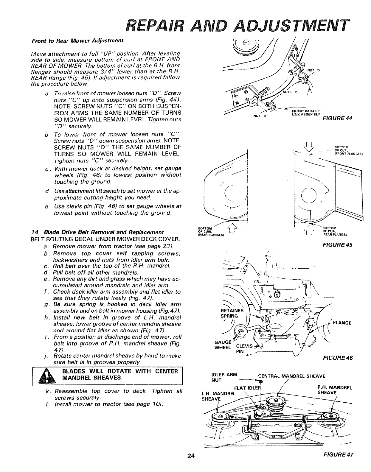
14, Blade Drive Belt Removal and Replacement
BELT ROUTING DECAL UNDER MOWER DECK COVER°
a, Remove mower from tractor (see page 23),
b. Remove top cover self tapping screws,
lock washers and nuts from idler atrn bolt.
c, Roll belt over the top of the R,.H. mandrel
d. Pull belt off all other mandrels,
e° Remove any dirt and grass which may have ac-
cumulated around mandrels and idler arm°
f o Check deck idler arm assembly and flat idler to
see that they rotate freely (Fig,. 47)_
go Be sure spring is hooked in deck idler arm
assembly and on bolt in mower housing (Fig,,47),.
h. Install new belt in groove of L.H, mandrel
sheave, lower groove of center mandrel sheave
and around flat idler as shown (Fig_ 47).
i. From a position at discharge end of mower, roll
belt into groove of R H, mandrel sheave (Fig,,
47).
j o Rotate center mandrel sheave by hand to make
sure belt is in grooves properly°
BLADES WILL ROTATE WITH CENTER
MANDREL SHEAVES,
k,. Reassemble top cover to deck, Tighten all
screws securely,,
Iv Install mower to tractor (see page 10),,
NUT D
NUT o
FRONT PARALLEL
LINK ASSEMBLY
FIGURE 44
BOTTOM
_. {FRONT FLANGESI
FIGURE 45
RETAINER
SPRING
J FLANGE
GAUGE _
WHEEL
CLEVIS /
PiN
FIG URE 46
iDLER ARM
NUT
CENTRAL MANDREL SHEAVE
24
FIGURE47
Loading ...
Loading ...