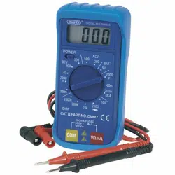
Loading ...
Loading ...
Loading ...
WARNINGS: Each time before you use this analyser, inspect the test leads, connectors
and probes for damage, e.g. cracks or breaks in the insulation. Any defective leads should
be replaced immediately. If the value to be measured is not known, set the selector switch
to the highest range and reduce until a satisfactory reading is obtained.
8.1 VOLTAGE MEASUREMENT:
1. Connect the red test lead to the ‘V//mA’ probe socket and the black lead to the ‘com’
probe socket Ensure the leads are correctly plugged in.
2. Position the selector switch to the desired voltage range and switch the meter ‘ON’.
3. Connect the test leads to the circuit to be measured.
4. Turn on the power to the circuit to be measured, the voltage value should appear on the
digital display along with the voltage polarity (if reversed only).
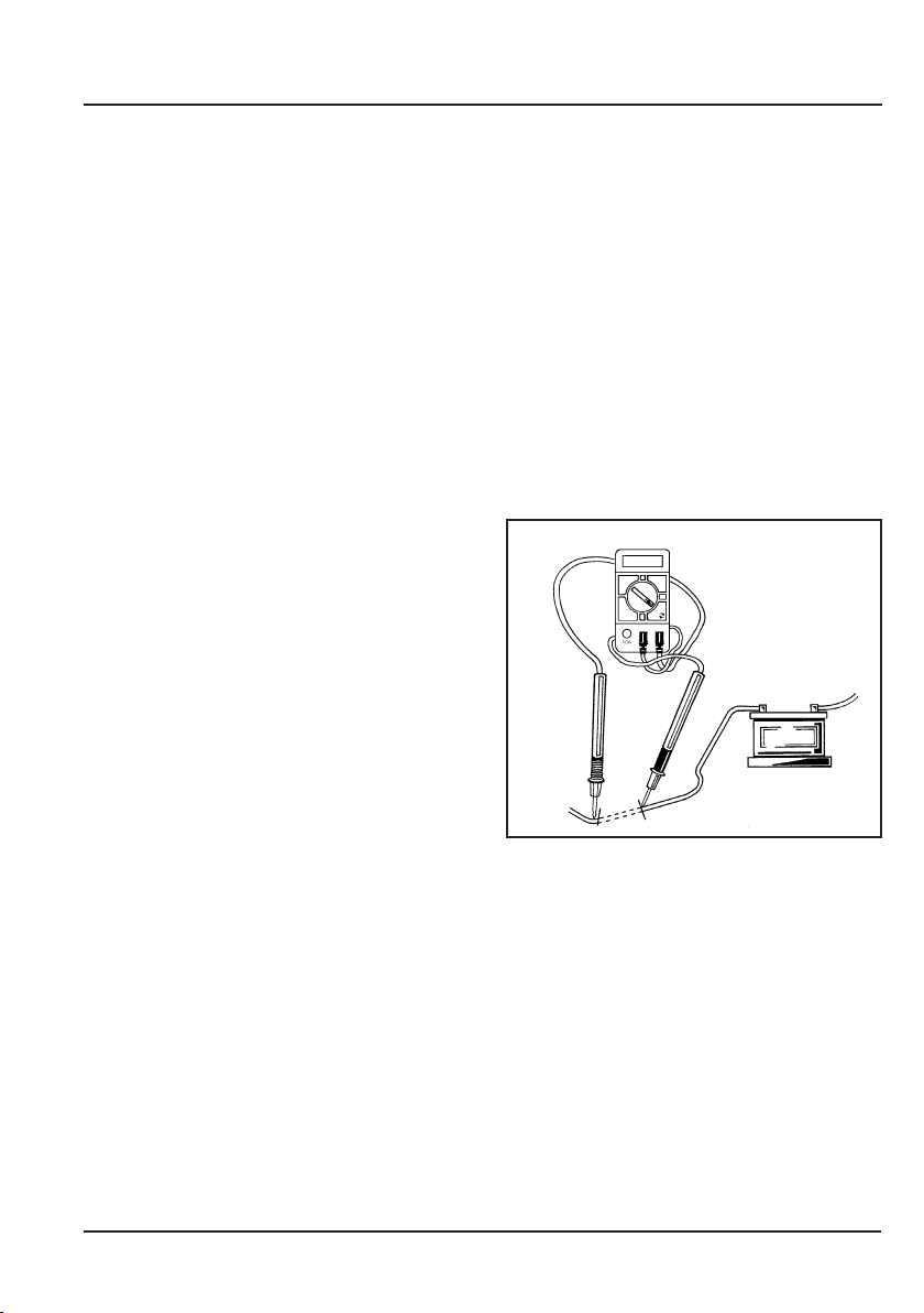
8.2 CURRENT MEASUREMENT - FIG.1
1. Connect the red test lead to the ‘V//mA’
probe socket and the black lead to the
‘com’ probe socket (max 10A).
2. Position the selector switch to the desired
amp range and switch the meter ‘ON’.
3. Open the circuit to be measured, and
connect the test leads in series to bridge
the gap.
4. Turn on the power to the circuit to be
measured, the ‘current’ value should
appear on the digital display.
8.3 RESISTANCE MEASUREMENT:
WARNING: If the resistance to be measured is part of a circuit, turn off and disconnect the
power and discharge all capacitors before measurement
1. Connect the red test lead to the ‘V//mA’ probe socket and the black lead to the ‘com’
probe socket.
2. Position the selector switch to the desired ohm range and switch the meter ‘ON’.
3. Connect the test leads to the circuit to be measured.
4. The resistance value should now appear on the digital display.
FIG.1
8. OPERATING INSTRUCTIONS
9
Loading ...
Loading ...
Loading ...