Loading ...
Loading ...
Loading ...
7
ASSEMBLY & INSTALLATION
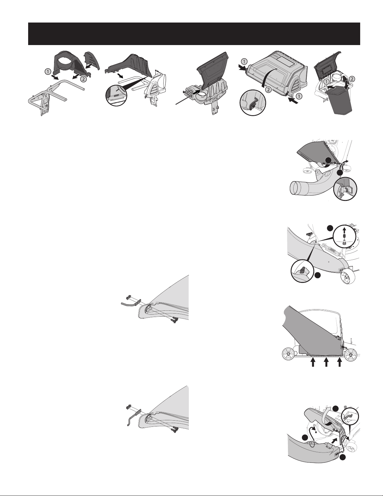
2. Snap the plastic upper chute support in place by first clipping the side
portion onto the bagger support rail (1) as shown in Figure 9.
3. Snap the front side of the chute support to the rail (2) as shown in Figure 9.
4. Snap the top cover support on to the bagger support rail at a slight angle.
Rotate the assembly down and into the chute support assembly, making sure
that the tab (shown in inset of Figure 10) is locked into place.
5. Install the bagger top cover by aligning the tabs of the cover and sliding the
hinge pin into the channel as shown in Figure 11.
6. Open hood by pushing in on the rear side tabs with your hand (1), and lifting
the cover with your other hand in the center rear of the bagger cover (2) as
shown in Figure 12.
7. Install both bag assemblies onto the bag support brackets by inserting the
front edge in first (1), and then setting the back edge down until it fits into the
assembly (2) as shown in Figure 13.
Installing the Boot Rod and Hardware
Model 19A70054*:
1. From the inside of the boot, put
the two Hex Head screws (738-
1225) through the holes at the
bottom front of the boot. See
Figure 14.
2. Put the mounting rod (747-06043)
in place over the hex head screws.
Make sure the tip of the rod is
facing out from the boot. See
Figure 14.
3. Begin threading the two flange lock nuts (712-04064) onto the hex head
screws. See Figure 14.
4. Using a 7/16” wrench or socket on the screw and a 7/16” box wrench on the
lock nuts, tighten down so flange is flush to secure the assembly.
Model 19A70055*:
1. From the inside of the boot,
put the two hex head screws
(738-1225) through the holes at
the bottom front of the boot. See
Figure 15.
2. Put the mounting rod (747-06309)
in place over the hex head screws.
Make sure the tip of the rod is
facing out from the boot. See
Figure 15.
3. Begin threading the two flange
lock nuts (712-04064) onto the hex head screws. See Figure 15.
4. Using a 7/16” wrench or socket on
the screw and a 7/16” box wrench
on the lock nuts, tighten down
so flange is flush to secure the
assembly.
Installing the Discharge
Chute - 42”/46” Double
Bagger
1. With the tractor’s discharge chute
raised up and held open (1), install
the chute elbow by placing the
chute elbow mounting rod into
the chute mounting tab (2), as
shown in Figure 16.
2. Secure the chute elbow to
the deck using a wing knob
(720-04122) from hardware pack
689-01419. See Figure 17.
NOTE: If present, remove the protective
cap off of the mounting stud on the
mowing deck as shown in the upper inset
of Figure 17.
IMPORTANT: Be certain that the
bottom of the discharge chute is
located inside of the lip of the deck
opening, as shown in Figure 18.
Installing the Discharge
Chute - 50/54” Double
Bagger
When installing the discharge chute,
two different installation instructions
exist. For the 54” Fabricated deck
units, the discharge chute elbow mounts directly onto the cutting deck. For the 50”
and 54” stamped decks, an adapter must first be installed. Be sure to follow the
instructions that pertain to the unit you
are installing this bagger on.
54” Fabricated Deck Units:
1. Raise the deck to its highest
position.
2. Raise the chute deflector (1 in
Figure 19) on the deck and hold it
while you position the discharge
chute over the chute opening.
Figure 14
Figure 15
1
2
Figure 16
1
2
Figure 17
Figure 18
1
2
3
Figure 19
Figure 9
Figure 10
Figure 11
Figure 12
Figure 13
Loading ...
Loading ...
Loading ...