Loading ...
Loading ...
Loading ...
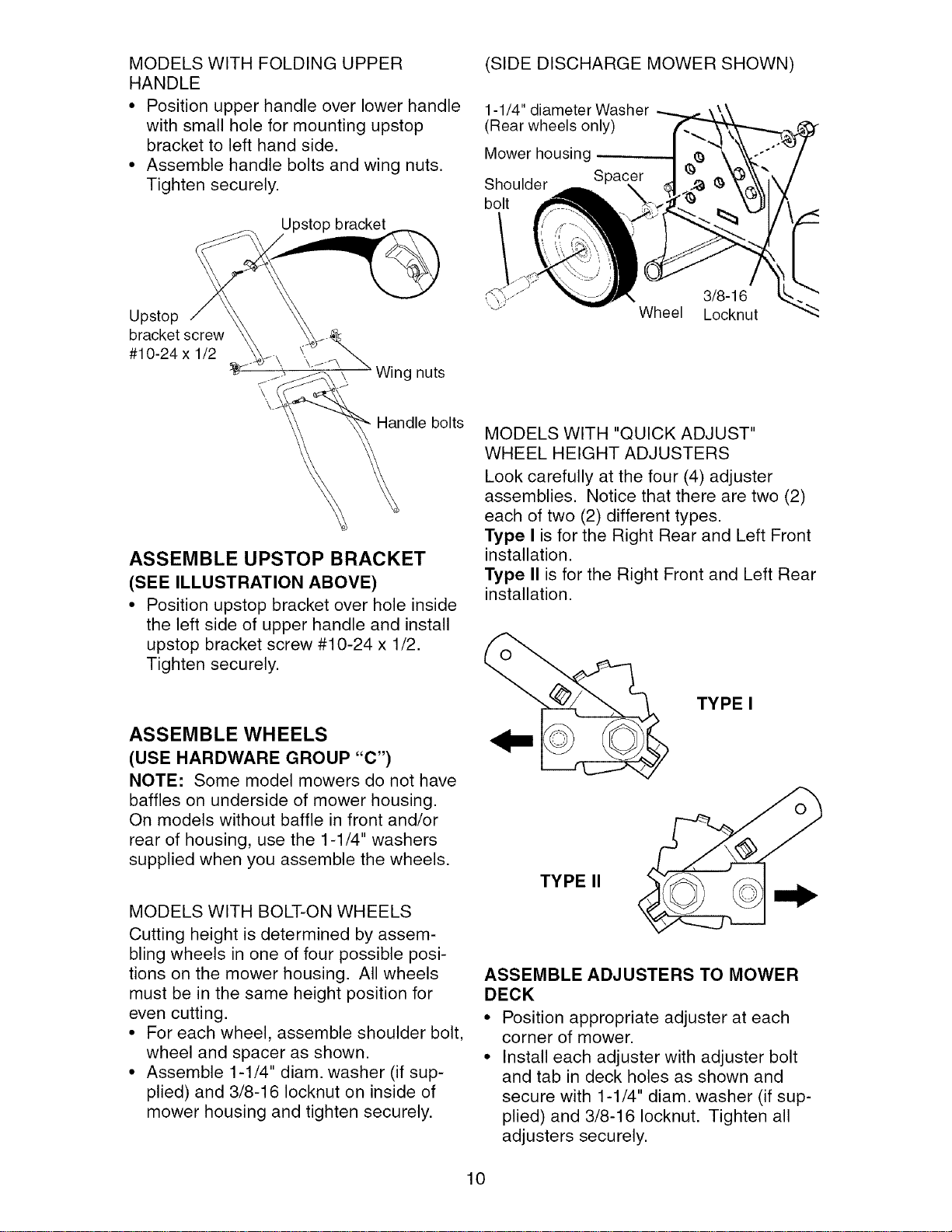
MODELS WITH FOLDING UPPER
HANDLE
• Position upper handle over lower handle
with small hole for mounting upstop
bracket to left hand side.
• Assemble handle bolts and wing nuts.
Tighten securely.
Upstop bracket
(SIDE DISCHARGE MOWER SHOWN)
1-1/4" diameter Washer
(Rear wheels only)
Mower housing
Shoulder Spacer
bolt
Upstop
bracket screw
#10-24 x 1/2
./ \. Wing nuts
\
Handle bolts
ASSEMBLE UPSTOP BRACKET
(SEE ILLUSTRATION ABOVE)
• Position upstop bracket over hole inside
the left side of upper handle and install
upstop bracket screw #10-24 x 1/2.
Tighten securely.
ASSEMBLE WHEELS
(USE HARDWARE GROUP "C")
NOTE: Some model mowers do not have
baffles on underside of mower housing.
On models without baffle in front and/or
rear of housing, use the 1-1/4" washers
supplied when you assemble the wheels.
MODELS WITH BOLT-ON WHEELS
Cutting height is determined by assem-
bling wheels in one of four possible posi-
tions on the mower housing. All wheels
must be in the same height position for
even cutting.
• For each wheel, assemble shoulder bolt,
wheel and spacer as shown.
• Assemble 1-1/4" diam. washer (if sup-
plied) and 3/8-16 Iocknut on inside of
mower housing and tighten securely.
3/8-16
Wheel Locknut
MODELS WITH "QUICK ADJUST"
WHEEL HEIGHT ADJUSTERS
Look carefully at the four (4) adjuster
assemblies. Notice that there are two (2)
each of two (2) different types.
Type I is for the Right Rear and Left Front
installation.
Type II is for the Right Front and Left Rear
installation.
TYPE I
TYPE II
ASSEMBLE ADJUSTERS TO MOWER
DECK
• Position appropriate adjuster at each
corner of mower.
• Install each adjuster with adjuster bolt
and tab in deck holes as shown and
secure with 1-1/4" diam. washer (if sup-
plied) and 3/8-16 Iocknut. Tighten all
adjusters securely.
10
Loading ...
Loading ...
Loading ...